EP2002165B1 - Tubular threaded joint - Google Patents
Tubular threaded joint Download PDFInfo
- Publication number
- EP2002165B1 EP2002165B1 EP07740952.2A EP07740952A EP2002165B1 EP 2002165 B1 EP2002165 B1 EP 2002165B1 EP 07740952 A EP07740952 A EP 07740952A EP 2002165 B1 EP2002165 B1 EP 2002165B1
- Authority
- EP
- European Patent Office
- Prior art keywords
- thread
- pin
- box
- joint
- stabbing
- Prior art date
- Legal status (The legal status is an assumption and is not a legal conclusion. Google has not performed a legal analysis and makes no representation as to the accuracy of the status listed.)
- Active
Links
Images


Classifications
-
- E—FIXED CONSTRUCTIONS
- E21—EARTH OR ROCK DRILLING; MINING
- E21B—EARTH OR ROCK DRILLING; OBTAINING OIL, GAS, WATER, SOLUBLE OR MELTABLE MATERIALS OR A SLURRY OF MINERALS FROM WELLS
- E21B17/00—Drilling rods or pipes; Flexible drill strings; Kellies; Drill collars; Sucker rods; Cables; Casings; Tubings
- E21B17/02—Couplings; joints
- E21B17/04—Couplings; joints between rod or the like and bit or between rod and rod or the like
- E21B17/042—Threaded
-
- F—MECHANICAL ENGINEERING; LIGHTING; HEATING; WEAPONS; BLASTING
- F16—ENGINEERING ELEMENTS AND UNITS; GENERAL MEASURES FOR PRODUCING AND MAINTAINING EFFECTIVE FUNCTIONING OF MACHINES OR INSTALLATIONS; THERMAL INSULATION IN GENERAL
- F16L—PIPES; JOINTS OR FITTINGS FOR PIPES; SUPPORTS FOR PIPES, CABLES OR PROTECTIVE TUBING; MEANS FOR THERMAL INSULATION IN GENERAL
- F16L15/00—Screw-threaded joints; Forms of screw-threads for such joints
- F16L15/001—Screw-threaded joints; Forms of screw-threads for such joints with conical threads
- F16L15/004—Screw-threaded joints; Forms of screw-threads for such joints with conical threads with axial sealings having at least one plastically deformable sealing surface
-
- F—MECHANICAL ENGINEERING; LIGHTING; HEATING; WEAPONS; BLASTING
- F16—ENGINEERING ELEMENTS AND UNITS; GENERAL MEASURES FOR PRODUCING AND MAINTAINING EFFECTIVE FUNCTIONING OF MACHINES OR INSTALLATIONS; THERMAL INSULATION IN GENERAL
- F16L—PIPES; JOINTS OR FITTINGS FOR PIPES; SUPPORTS FOR PIPES, CABLES OR PROTECTIVE TUBING; MEANS FOR THERMAL INSULATION IN GENERAL
- F16L15/00—Screw-threaded joints; Forms of screw-threads for such joints
- F16L15/06—Screw-threaded joints; Forms of screw-threads for such joints characterised by the shape of the screw-thread
Definitions
- This invention relates to a tubular threaded joint suitable for use in connecting steel pipes such as oil country tubular goods (OCTG), riser pipes, and line pipes. More particularly, it relates to a tubular threaded joint which has excellent resistance to compression and which makes it easy to connect steel pipes in a vertical state in the field.
- OCTG oil country tubular goods
- riser pipes riser pipes
- line pipes line pipes. More particularly, it relates to a tubular threaded joint which has excellent resistance to compression and which makes it easy to connect steel pipes in a vertical state in the field.
- Steel pipes such as OCTG (oil country tubular goods including oil well tubing, casing, and drill pipes) used for the exploration and production of oil wells and gas wells, as well as riser pipes, line pipes, and the like are usually connected by a tubular threaded joint.
- OCTG oil country tubular goods including oil well tubing, casing, and drill pipes
- a tubular threaded joint is constituted by a pin, which is a male threaded element provided on an end portion of a first tubular member, and a box, which is a female threaded element provided on an end portion of a second tubular member. Connection is carried out by engagement of the male screw thread and the female screw thread, which are both tapered screw threads.
- the first tubular member is a pipe such as an oil country tubular good
- the second tubular member is a separate member in the form of a coupling (this type of tubular threaded joint is referred to as a coupling type). With this type, a pin is formed on both ends of the pipe, and a box is formed on both sides of the coupling.
- the pin and the box each have, in addition to a tapered screw thread, a metal-to-metal seal surface, which makes direct metallic contact in the radial direction between mating members of the joint possible thereby forming a seal, and a torque shoulder surface which serves as an abutting stopper during tightening of the joint.
- Figures 1(A) and 1(B) are schematic explanatory views of a typical premium joint for oil country tubular goods of the coupling type.
- Figure 1(A) is an overall view
- Figure 1(B) is an enlarged view of a portion thereof.
- this tubular threaded joint has a pin 1 which is a male threaded element provided on each end portion of a pipe and a box 2 which is a corresponding female threaded element provided on both sides of a coupling.
- the pin 1 On its outer surface, the pin 1 has a tapered male threaded zone 11 and an unthreaded generally cylindrical abutting portion 12 called a lip (referred to below as a lip zone) adjacent to the male threaded zone 11 on the side closer to the end.
- the lip zone 12 has a metal-to-metal seal surface 13 (also referred to below simply as a seal surface) on its outer peripheral surface and a torque shoulder surface 14 (also referred to below simply as a shoulder surface) on its end surface.
- the corresponding box 2 has on its inner surface a tapered female threaded zone 21, a metal-to-metal seal surface 23, and a shoulder surface 24 which can interfit with, contact, or abut against the tapered male threaded zone 11, the metal-to-metal seal surface 13, and the shoulder surface 14, respectively, of the pin 1.
- Figure 2 is a schematic view for explaining the shape and dimensions of a trapezoidal thread typified by a buttress thread specified by API.
- 11 is a male threaded zone and 21 is a female threaded zone.
- a screw thread used in a premium joint is usually a trapezoidal screw thread modeled on this API buttress screw thread.
- Most premium joints employ the dimensions of an API buttress screw thread with almost no changes with respect to the aspect ratio (height-to-width ratio), the flank angles (the angle of slope of the flanks), and the like of screw thread.
- the thread height 74 which is the height to the crest of a male thread, is 1.575 mm
- the angle of slope 71 of the load flank is 3°
- the angle of slope 72 of the stabbing flank is 10°
- the clearance 73 in the pipe axial direction between the stabbing flanks of the male screw thread and the female screw thread when the load flanks contact each other is an average of approximately 100 ⁇ m (30 - 180 ⁇ m).
- WO 92/15815 describes a tubular threaded joint in which the portion connecting the thread crest and the stabbing flank of each thread of both a pin and a box is cut away along a straight line or a curve (namely, it is chamfered) such that it can function as a contact surface which is the first to contact when the pin is inserted into the box.
- the contact surfaces of the pin and the box are intended to contact each other to facilitate insertion when axial misalignment occurs during insertion of the pin into the box.
- U.S. Patent No. 6,322,110 discloses a tubular threaded joint based on the same concept. Namely, a corner chamfer (chamfer of a corner portion) is provided on the stabbing flanks of the threads of both a pin and a box. When the pin is inserted into the box, the corner chamfers engage with each other and facilitate insertion of the pin.
- a corner chamfer chamfer of a corner portion
- the shoulder surfaces of the pin and the box function as stoppers which abut at the time of tightening of the joint, and they also have the function of bearing a considerable proportion of the compressive load which acts on the joint. Accordingly, if the thickness of the shoulder surfaces is not large (or if the stiffness of the shoulder surfaces is not high), they cannot withstand a large compressive load.
- the wall thickness of the shoulder surfaces (the area for receiving compressive loads which corresponds to the area of the lip end surface) is normally considerably smaller than that of the pipe body. Therefore, if a compressive load corresponding to 40 - 60% of the yield strength of the pipe body is applied, with most premium joints, the lip zone of the pin undergoes a substantial plastic deformation, leading to a marked decrease in the sealing performance of the seal surface adjacent to this portion.
- the sealing ability of a joint against external pressure can be increased by increasing the stiffness of the pin so as to increase its resistance to deformation toward a reduction in diameter.
- a technique called swaging is often applied to the pipe towards the axis in order to increase the wall thickness of the lip zone.
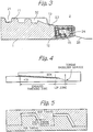
- WO 2004/109173 proposes a tubular threaded joint, as shown in Figure 3 , having a nose portion 15 provided between a metal-to-metal seal surface 13 and a torque shoulder surface 14 on the end surface of a pin 1.
- the generally cylindrical outer periphery of the nose portion 15 of the pin 1 does not contact the opposing portion of the box 2.
- the metal-to-metal seal portions 13 and 23 and the shoulder surfaces 14 and 24 of the pin and the box contact each other.
- the wall thickness of the lip zone including the shoulder surface and the seal surface can achieve a large value within a limited pipe wall thickness, and the resistance to compression and the sealing performance against external pressure of a tubular threaded joint can be markedly increased.
- US 6, 237, 967 discloses a tubular threaded joint comprising a pin which is a male threaded element formed on an end portion of a first tubular member and a box which is a female threaded element formed on an end portion of a second tubular member, the pin and the box each having a threaded zone and at least one torque shoulder surface, the male threaded zone of the pin engaging with the female threaded zone of the box, the at least one torque shoulder surface of the pin abutting against the at least one torque shoulder surface of the box in the axial direction of the pipe, one of the abutting torque shoulder surfaces being an end shoulder surface constituting an end surface in the transverse direction of the member, the threads of the male threaded zone and the female threaded zone being generally trapezoidal threads which have a thread crest, a load flank, and a stabbing flank and which have a root separating the thread.
- WO 2006/022418 discloses a threaded joint for steel pipes which are connected by threaded engagement of a pin member having a tapered male thread, a metal seal-forming portion, and a torque shoulder-forming portion on the end of a pipe, and a box member having a tapered female thread, a metal seal-forming portion, and a torque shoulder forming-portion corresponding to these on the end of a pipe, a buttress thread having contact at the load flanks and the thread root surface and gaps at the thread crest surface and the stabbing flanks is mixed in a single joint with a rugged thread having contact at the load flanks and stabbing flanks and having gaps at the thread root surface and thread crest surface.
- the present invention relates to a tubular threaded joint comprising a pin which is a male threaded element formed on an end portion of a first tubular member and a box which is a female threaded element formed on an end portion of a second tubular member, the pin and the box each having a threaded zone and at least one torque shoulder surface, the male threaded zone of the pin engaging with the female threaded zone of the box, the at least one torque shoulder surface of the pin abutting against the at least one torque shoulder surface of the box in the axial direction of the pipe, one of the abutting torque shoulder surfaces being an end shoulder surface constituting an end surface in the transverse direction of the member, the threads of the male threaded zone and the female threaded zone being generally trapezoidal threads which have a thread crest, a load flank, and a stabbing flank and which have a root separating the thread, wherein the lip length of the member having an end shoulder surface, which is the axial distance between the end shoulder surface and the load flank
- the length of the lip zone which is the distance in the member having a contacting end shoulder surface of a tubular threaded joint between the engaged threaded zone and the end shoulder surface, to at least 140 times and preferably at least 160 times the stabbing flank clearance of the male and female threads
- resistance to compression is effectively conferred by the stabbing flanks of the threads (or by the remaining effective or engaged portions of the stabbing flanks when the upper portion of the stabbing flank of the pin or the box has been removed by chamfering or beveling), and the resistance to compression of a tubular threaded joint is increased.
- the stabbing flank clearance By controlling the stabbing flank clearance to be within a certain range, variations in the tightening force at the time of tightening the threaded joint can be decreased.
- the shape of the threads and particularly the direction of the crest and the root, the shape of a stabbing flank, and the shape of the chamfer on the stabbing flank side problems and misengagement of threads due to deviation of the insertion angle at the time of restricted tightening operation such as tightening operation in the field in a vertical state which is being increasingly automated can be decreased, thereby making such a tightening operation easy.
- a tubular threaded joint according to the present invention can be applied to either a coupling-type or an integral-type tubular threaded joint.
- a coupling type typically a pin is formed on both ends of a pipe and a box is formed on both sides of a coupling, but it is possible to use the opposite combination.
- a pin has a threaded zone having a male screw thread which engages with an opposing female screw thread (an engaged thread zone in the figure), and a lip zone on the end side thereof which does not have engaged threads.
- the end surface in the transverse direction at the tip of the pin is an end shoulder surface functioning as a torque shoulder surface.
- a box has on its outer end a threaded zone having a female screw thread which engages with the opposing male screw thread and, on the inner side thereof, a generally cylindrical surface which does not have engaged threads.
- the surface in the transverse direction of the innermost portion of the box is a torque shoulder surface which abuts against the end shoulder surface of the pin.
- the shoulder surfaces of the pin and the box which abut against each other are in many cases an end shoulder surface of the pin and a corresponding innermost shoulder surface of the box.
- the surface area of the end surface of a pin having a male screw thread formed on the outer surface of one end of a pipe is sometimes smaller than the surface area of the end surface of a box having a female screw thread formed on the other end of the pipe.
- the lip zone means the portion of a threaded joint member (a pin or a box) having an end shoulder surface (which functions as a torque shoulder surface at the time of tightening of the threaded joint) which is located closer to the end of the joint member than the engaged thread portion thereof.
- the screw threads of the threaded zones of the pin and the box engage with each other. However, it is not necessary for the threads to engage along the entire length. As shown in Figure 1 (B) , the end portions of the screw thread of one or both members and particularly the screw thread in the vicinity of the tip of the box need not be engaged with screw thread of the other member. In addition, as shown in Figure 3 , an unengaged male thread can be added to a portion of the outer surface of the pin between the engaged threaded zone and the lip zone. By doing so, the stiffness of the pin against external pressure can be increased. In the present invention, the unengaged thread formed on the outer end (closer to the tip) of the threaded zone of a member (pin or box) having an end shoulder surface are included within the lip zone of the member.
- a tubular threaded joint has a metal-to-metal seal portion.
- the outer surface of the lip zone of a pin and the unthreaded generally cylindrical inner surface of a box have a portion in which they contact each other to form metal-to-metal seal surfaces 13 and 23, as shown in Figure 3 .
- the metal-to-metal seal surfaces are preferably provided in a region of the lip zone which is close to the threaded zone, as illustrated.
- a noncontacting region where the generally cylindrical surfaces of the pin and box do not contact each other is preferably provided in the lip zone at a location between the metal-to-metal seal surfaces 13, 23 and the shoulder surfaces 14, 24.
- the noncontacting region in the lip zone can further increase the resistance to compression of that portion.
- the inner surfaces of the pin and the box on both sides of the shoulder surfaces can be removed to form chamfered portions 16 and 26. As a result, circularity of the interior of the pipe around the abutting shoulder surfaces can be achieved so that the occurrence of turbulence of fluid flowing through the joint can be prevented.
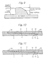
- FIG. 5 schematically shows threads of a tubular threaded joint in longitudinal section of the joint.
- all the corners of the threads shown therein are not chamfered at all.
- each of the engaged threads of the pin and the box has a crest, a load flank which is the thread flank on the rear side in the direction of insertion of the pin, and a stabbing flank which is the thread flank on the front side in the direction of insertion of the pin, and adjacent thread flanks are separated by a root.
- Figure 5 shows an example in which the stabbing flanks of the male screw thread and the female screw thread are parallel so that the stabbing flank clearance is uniform over the entirety of the stabbing flanks of the engaged threads.
- the distance in the axial (longitudinal) direction of the member between the end shoulder surface and the load flank of the engaged thread located closest to the end shoulder surface is at least 140 times and preferably at least 160 times the stabbing flank clearance.
- the threaded zone the threaded zone of the pin in the illustrated example
- the axial length of this unengaged thread portion namely, the axial length of a cylindrical groove 32 provided on a box 2 in Figure 3 , is included in the lip length.
- a member having an end shoulder surface which abuts against an opposing innermost shoulder surface of the other member of a tubular threaded joint is typically a pin.
- the lip length of the pin satisfies the above-described requirements with respect to the stabbing flank clearance.
- this end shoulder surface is sometimes provided on the box.
- the lip length of the box is made to satisfy the above-described requirement.
- the threads act in compression while the strain of the lip zone remains in the elastic region. If the lip length is at least 140 times and preferably at least 160 times the stabbing flank clearance, even if a threaded joint undergoes compression in the pipe axial direction due to external pressure, the lip zone does not begin to undergo plastic deformation, and the stabbing flanks of the threads can contribute to resistance to compression while the strain of the lip zone remains in the state of elastic deformation. As a result, the resistance to compression of a tubular threaded joint is markedly increased.
- the stabbing flank clearance is preferably at least 0.01 mm (10 ⁇ m) and at most 0.3 mm (300 ⁇ m). If the stabbing flank clearance is smaller than 0.01 mm, the clearance is so small that tightening of a threaded joint becomes unstable, and it becomes easy for galling to occur. On the other hand, if the stabbing flank clearance is larger than 0.3 mm, the clearance is so large as to allow external pressure to easily penetrate, thereby unduly increasing the external pressure to be applied to the lip zone during tightening. As shown in Figure 5 , there is also a clearance in the radial direction of the joint between the crest of a male thread and the root of a female thread engaged therewith. There is no particular limitation on the dimension of this clearance in the radial direction, but normally it is designed so that a sufficient clearance can be achieved taking into consideration the tolerances of the thread height.
- the stabbing flank of each thread comprises two portions in the form of a first portion on the root side and a second portion on the crest side.
- the second portion has a larger average angle of slope with respect to a line perpendicular to the longitudinal axis than the first portion (namely, the second portion has a steeper slope than the first portion).
- the overall thread height in the engaged threaded zone of a tubular threaded joint (the height in the radial direction from the root to the crest of a thread) is designed so that the strength of the joint is at least the strength of the pipe body under a tensile load.
- the abutting shoulder surfaces also receive the applied load. Accordingly, the compressive load borne by the threads is reduced by the amount received by the cross-sectional area of the abutting shoulder surfaces.
- the thread height necessary for supporting a load is smaller under a compressive load than under a tensile load.
- a tensile load is borne by the load flanks of the engaged threads of a joint in the state shown in Figure 5 in which the load flanks contact each other, while a compressive load is borne by the stabbing flanks of the engaged threads in an unshown state in which the stabbing flanks contact each other. Therefore, the thread height on the stabbing flank side of the threads includes a margin.
- compression rate of the joint can be expressed by the ratio of the total cross-sectional area in the transverse or radial direction of the compression-receiving surfaces of the joint to the radial cross-sectional area of the pipe body, which is given by the following equation.
- Compression rate % cumulative projected cross ⁇ sectional area of engaged threads + cross ⁇ sectional area of abutting shoulder surfaces / cross ⁇ sectional area of pipe body ⁇ 100.
- the cross-sectional area of abutting shoulder surfaces is typically about 40 - 50 % of that of pipe body. Therefore, even with a compression rate of 100% in which a compressive load corresponding to the yield strength of the pipe body is applied to a tubular threaded joint, the joint can withstand the compressive load if the thread height of the stabbing flanks is at least 50 - 60% of the overall thread height.
- the remaining second portion on the crest side of the stabbing flanks may have a larger angle of slope, which makes the portion unable to receive a compressive load, and even in this case, a sufficient resistance to compression can be achieved.
- the height in the radial direction of the first portion of the chamfered stabbing flank of the male thread of the pin is preferably set such that the product of the height in the radial direction of this first portion and the developed thread length of the engaged threads (pin and box screw threads engaged with each other) is larger than the difference between the nominal radial cross-sectional area of the body of the pipes being connected and the radial cross-sectional area of the abutting shoulder surfaces of the joint.
- the joint can have resistance to compression which can withstand a compressive load corresponding to the above-mentioned 100% compression rate.
- the cross-sectional area of the pipe body of course means the cross-sectional area in the radial direction of the wall of the pipe.
- the second portion of the stabbing flank By giving the second portion of the stabbing flank a chamfered shape which is optimal from the standpoint of tightening operation in the field, it is possible to realize an easy tightening operation in the field while maintaining excellent resistance to compression achieved by the first portion.
- the first portion of the stabbing flank of the screw thread of a member should be parallel to the stabbing flank of the screw thread of the other member so as to make a uniform stabbing flank clearance in the first portion and allow the first portion of the stabbing flank to uniformly contact the stabbing flank of the other screw thread at the time of tightening the joint. Accordingly, the first portion of the stabbing flank of the screw thread and the stabbing flank of the other screw thread are generally conical surfaces.
- a generally conical surface means a surface substantially limited in longitudinal section (along the pipe axis) by a straight line. More specifically, it means that at least 50% and preferably at least 80% of the height is conical or is limited in longitudinal section by a straight line.
- a generally conical surface includes the case in which the upper end and/or the lower end is slightly rounded.
- a chamfer of the second portion is a chamfer such that the cross section in the pipe axial direction is linear (a chamfer with a generally conical surface), or as shown in Figure 7 , it may be a chamfer such that the axial cross section is arcuate (a convex bulging surface (not in accordance with the invention) or a concave surface (not in accordance with the invention).
- Figure 7 shows an example of a bulging surface not in accordance with the invention. It is also possible for a chamfer to combine these shapes.
- the angle of slope of the surface with respect to a line perpendicular to the pipe axis is preferably in the range of 5 - 25°.
- the average angle of slope of the second portion with respect to a line perpendicular to the pipe axis is preferably in the range of 20 - 70°, as shown in Figure 8 .
- each female screw thread also has two portions with different angles of slope.
- the crests and roots of the screw threads are parallel to the pipe axial direction for all the male and female threads. Namely, although the threaded zones of the pin and the box of a tubular threaded joint are in the form of tapered screw threads, the crest and root of each thread are not parallel to the tapered slope but parallel to the pipe axis. In this manner, problems due to deviation of the insertion angle of a pin at the time of tightening operation in the field are reduced.
- the angle with respect to a line perpendicular to the pipe axis of the load flanks of the threads of the pin and the box is preferably in the range of -5° to +5°.
- the angle of slope of a load flank is negative, it means, as shown in Figures 5 - 9 , for example, that the load flank is leaning leftwards in the figures with respect to a line perpendicular to the pipe axis.
- the load flank of the thread of at least one of the pin and the box and preferably of the male thread of the pin may also comprise two portions in the form of a third portion on the root side and a fourth portion on the crest side, as shown in Figures 6 - 9 and particularly in Figure 9 .
- the fourth portion should have a larger average angle of slope (on the plus side) with respect to a line perpendicular to the pipe axis than the third portion.
- the third portion of the load flank is preferably a generally conical surface, and its angle of slope is preferably in the range of -5° to +5°.
- the fourth portion may be a generally conical surface as shown in the figure, or it may be a bulging surface.
- the fourth portion of a load flank is also a kind of chamfer which makes it easy to insert a pin into a box at the time of tightening in the field.
- a tensile load is borne only by the load flanks, and there is no contribution by the shoulder surfaces to resisting tensile force. Therefore, it is necessary to make the area of the contact portions of the male thread and the female thread larger for the load flanks (the third portion thereof) than for the stabbing flanks (the first portion thereof).
- the fourth portion of a load flank have a smaller height than the second portion of a stabbing flank so that an adequate area for contact is left in the third portion of the load flank which contributes to tensile performance. For this reason, the height of the fourth portion is preferably at most 20% of the thread height.
- Both the pin and the box preferably have a metal-to-metal seal surface between the shoulder surface and the engaged thread portion, i.e., in the lip zone.
- the lip length is at least 140 times the stabbing flank clearance of the thread, which is considerably longer compared to a conventional one.
- the metal-to-metal seal surface is provided over a portion of the lip zone and preferably in a region thereof close to the threaded zone.
- the length of the metal-to-metal seal portion is preferably at most 25% of the lip length.
- the pin and the box each preferably have a noncontacting region (where they do not contact each other) between the metal-to-metal seal surface and the shoulder surface.
- a noncontacting region between the metal-to-metal seal surface and the shoulder surface By providing such a noncontacting region between the metal-to-metal seal surface and the shoulder surface, the length of the lip zone can be increased, and at the time of application of a compressive load, it becomes possible for the compressive load to be supported by the contacting stabbing flanks of the threaded zones of the pin and the box and the abutting shoulder surfaces while the strain of the lip zone remains in the elastic region, and the lip zone including the metal-to-metal seal surface takes on a design which is resistant to plastic deformation due to compression.
- This noncontacting region may be a portion in which either the pin or the box does not have threads as shown in Figure 3 , or it may be an unengaged thread portion in which only one member of the pin and box has threads, or it may include both portions.
- the length of this noncontacting region is preferably at least 15% of the lip length.
- the length of a portion of a noncontacting region which does not have threads in either member is preferably at most 33% of the lip length.
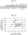
- an end shoulder surface and a metal-to-metal seal surface are not limited to one location, and as shown in Figure 10 , a second end shoulder surface 33 can be provided at the tip end of the box 2, or as shown in Figure 11 , a second metal-to-metal seal surfaces 34 can be provided on both members near the tip end of the box 2.
- the thicknesses of a pipe and/or a coupling can be increased in the vicinity of the joint portion by swaging or overlaying.
- test members shown in Table 1 were a threaded joint for oil country tubular goods of the coupling type like that shown in Figure 3 . They were for use with respect to a 9.625" x 53.5 (lb/ft) steel pipe (outer diameter of 244.5 mm and wall thickness of 13.84 mm).
- the steel used for all of the test members was that specified by API specification P110.
- the shoulder surfaces were an end shoulder surface located at the end of the pin and a corresponding shoulder surface of the box.
- the lip zone had on its outer periphery a metal-to-metal seal surface (length of 5.5 mm) in the vicinity of the threaded zone and a noncontacting region on the outer end side thereof. In contrast to Figure 3 , there was no unengaged thread on the end portion of the threaded zone.
- the screw thread shape was the same for all the test members, with a taper of 1/18, a male thread height 74 of 1.3 mm, a thread pitch of 5.08 mm, a stabbing flank angle 72 of 10°, and a load flank angle 71 of -3°.
- a chamfer of the stabbing flanks and the load flanks for both the male screw thread and the female screw thread was only a minimal rounding as shown in Figure 2 , and the stabbing flanks consisted essentially of only one portion.
- the stabbing flank clearance 73 and the length of the lip zone of the joint were varied as shown in Table 1.
- the stabbing flank of the male thread of the pin was divided into a first portion on the root side and a second portion on the crest side having different slope angles.
- the first portion and the second portion of the stabbing flanks were both made conical surfaces (namely, having a longitudinal section along the pipe axis substantially formed by a straight line).
- the angle of slope of the stabbing flank was 10° for the first portion and 45° for the second portion.
- the ratio of the lip length to the stabbing flank clearance was 200 (the stabbing flank clearance was 0.1 mm and the lip length was 20 mm).
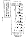
- the thread stabbing flank height ratio in Table 2 was varied as shown in Table 2.
- the diameter of the end portion of the lip zone i.e., the area of the end shoulder surface of the pin
- the ratio of the cross-sectional area of the abutting shoulder surfaces and that of the cumulative cross-sectional area of engaged (effective) stabbing flanks was varied as shown in the column of cross-sectional area ratio in Table 2.
- the pin end was subjected to swaging so as to have an increased wall thickness and hence an increased cross-sectional area of the end shoulder portion at its end.
Landscapes
- Engineering & Computer Science (AREA)
- General Engineering & Computer Science (AREA)
- Mechanical Engineering (AREA)
- Geology (AREA)
- Life Sciences & Earth Sciences (AREA)
- Mining & Mineral Resources (AREA)
- Environmental & Geological Engineering (AREA)
- Fluid Mechanics (AREA)
- General Life Sciences & Earth Sciences (AREA)
- Geochemistry & Mineralogy (AREA)
- Physics & Mathematics (AREA)
- Non-Disconnectible Joints And Screw-Threaded Joints (AREA)
- Earth Drilling (AREA)
- Mutual Connection Of Rods And Tubes (AREA)
Priority Applications (1)
| Application Number | Priority Date | Filing Date | Title |
|---|---|---|---|
| PL07740952T PL2002165T3 (pl) | 2006-03-31 | 2007-03-28 | Rurowe złącze gwintowe |
Applications Claiming Priority (2)
| Application Number | Priority Date | Filing Date | Title |
|---|---|---|---|
| JP2006099296 | 2006-03-31 | ||
| PCT/JP2007/057516 WO2007114460A1 (en) | 2006-03-31 | 2007-03-28 | Tubular threaded joint |
Publications (3)
| Publication Number | Publication Date |
|---|---|
| EP2002165A1 EP2002165A1 (en) | 2008-12-17 |
| EP2002165A4 EP2002165A4 (en) | 2014-03-12 |
| EP2002165B1 true EP2002165B1 (en) | 2017-09-06 |
Family
ID=38563721
Family Applications (1)
| Application Number | Title | Priority Date | Filing Date |
|---|---|---|---|
| EP07740952.2A Active EP2002165B1 (en) | 2006-03-31 | 2007-03-28 | Tubular threaded joint |
Country Status (16)
| Country | Link |
|---|---|
| US (1) | US7823931B2 (pl) |
| EP (1) | EP2002165B1 (pl) |
| JP (1) | JP4924614B2 (pl) |
| CN (1) | CN101438089B (pl) |
| AR (1) | AR060258A1 (pl) |
| AU (1) | AU2007232748B2 (pl) |
| BR (1) | BRPI0710261B1 (pl) |
| CA (1) | CA2647447C (pl) |
| EA (1) | EA014091B1 (pl) |
| EG (1) | EG25061A (pl) |
| MX (1) | MX2008012234A (pl) |
| MY (1) | MY142893A (pl) |
| NO (1) | NO342162B1 (pl) |
| PL (1) | PL2002165T3 (pl) |
| UA (1) | UA91751C2 (pl) |
| WO (1) | WO2007114460A1 (pl) |
Families Citing this family (57)
| Publication number | Priority date | Publication date | Assignee | Title |
|---|---|---|---|---|
| US20100018857A1 (en) * | 2008-07-23 | 2010-01-28 | Seagate Technology Llc | Sputter cathode apparatus allowing thick magnetic targets |
| US8246086B2 (en) * | 2008-09-10 | 2012-08-21 | Beverly Watts Ramos | Low cost, high performance pipe connection |
| SE534883C2 (sv) * | 2009-03-26 | 2012-01-31 | Sandvik Intellectual Property | Del hos ett förband i ett tunnväggigt borrör, förbandssystem och tunnväggigt borrörssystem. |
| FR2953272B1 (fr) * | 2009-11-30 | 2011-12-16 | Vallourec Mannesmann Oil & Gas | Joint filete |
| US20150176341A1 (en) | 2010-01-28 | 2015-06-25 | Sunstone Technologies, Llc | Tapered Spline Connection for Drill Pipe, Casing, and Tubing |
| US20110180273A1 (en) * | 2010-01-28 | 2011-07-28 | Sunstone Technologies, Llc | Tapered Spline Connection for Drill Pipe, Casing, and Tubing |
| EP2568112B1 (en) * | 2010-05-06 | 2019-01-23 | Nippon Steel & Sumitomo Metal Corporation | Test apparatus for a threaded joint for oil country tubular goods |
| FR2961576B1 (fr) | 2010-06-17 | 2012-08-03 | Vallourec Mannesmann Oil & Gas | Joint filete et procede de realisation |
| MX2013000387A (es) | 2010-07-02 | 2013-03-22 | Sunstone Technologies Llc | Cableado electrico para varilla de perforacion, revestimiento y tuberia. |
| US20120298249A1 (en) * | 2011-05-24 | 2012-11-29 | Banker Edward O | Tubular connection and associated thread form |
| US9637983B2 (en) * | 2011-11-25 | 2017-05-02 | Klimack Holdings Inc. | Casing connection |
| FR2985282B1 (fr) * | 2011-12-29 | 2016-07-29 | Vallourec Mannesmann Oil & Gas France | Joint filete a faible couple de vissage |
| CN102678071A (zh) * | 2012-06-06 | 2012-09-19 | 无锡西姆莱斯石油专用管制造有限公司 | 高密封特殊偏梯形螺纹套管连接接头 |
| UA112576C2 (uk) * | 2012-06-07 | 2016-09-26 | Ніппон Стіл Енд Сумітомо Метал Корпорейшн | Нарізне з'єднання для сталевої труби |
| JP2014013052A (ja) * | 2012-07-04 | 2014-01-23 | Jfe Steel Corp | 管のねじ継手 |
| US9677346B2 (en) | 2012-11-28 | 2017-06-13 | Ultra Premium Oilfield Services, Ltd. | Tubular connection with helically extending torque shoulder |
| US9869139B2 (en) | 2012-11-28 | 2018-01-16 | Ultra Premium Oilfield Services, Ltd. | Tubular connection with helically extending torque shoulder |
| JP5803953B2 (ja) | 2013-02-18 | 2015-11-04 | Jfeスチール株式会社 | 管接続用ねじ継手 |
| JP5742885B2 (ja) * | 2013-06-14 | 2015-07-01 | Jfeスチール株式会社 | 耐焼付き性に優れた油井管用ねじ継手 |
| MX2016007276A (es) | 2013-12-05 | 2016-08-11 | Nippon Steel & Sumitomo Metal Corp | Union roscada para tuberias de acero. |
| FR3014534B1 (fr) * | 2013-12-10 | 2015-12-04 | Vallourec Oil & Gas France | Ensemble pour la realisation d'un joint filete pour le forage et l'exploitation des puits d'hydrocarbures et joint filete resultant |
| JP6560224B2 (ja) * | 2013-12-16 | 2019-08-14 | マルベニ−イトウチュウ チューブラーズ アメリカ インコーポレイテッドMarubeni−Itochu Tubulars America Inc. | ねじ接続部 |
| WO2015105054A1 (ja) * | 2014-01-09 | 2015-07-16 | 新日鐵住金株式会社 | 鋼管用ねじ継手 |
| US9593786B1 (en) * | 2014-10-01 | 2017-03-14 | Precision Couplings, Llc | Leak proof threaded connector |
| FR3027338B1 (fr) | 2014-10-16 | 2016-12-02 | Vallourec Oil & Gas France | Connexion polyvalente etanche a double butee |
| CN104533310B (zh) | 2014-12-05 | 2017-02-01 | 中国石油天然气集团公司 | 铝合金钻杆管体与接头的连接结构 |
| NO20150217A1 (en) * | 2015-02-13 | 2016-08-15 | Arne Barrett Sele | Threaded connector |
| US10006569B2 (en) | 2015-02-19 | 2018-06-26 | Arcelormittal Tubular Products Luxembourg S.A. | Threaded connection for pipes, such as oil and gas pipes |
| JP6689028B2 (ja) * | 2015-03-19 | 2020-04-28 | 株式会社ディビーエス | 鉄筋の継手方法 |
| WO2017001496A1 (en) * | 2015-07-01 | 2017-01-05 | Shell Internationale Research Maatschappij B.V. | Expanding well tubulars interconnected by pin-box assemblies optimized for expansion |
| CA3001670C (en) * | 2015-10-21 | 2020-04-14 | Nippon Steel Corporation | Threaded connection for steel pipe |
| US11466800B2 (en) | 2015-12-09 | 2022-10-11 | Certus Energy Solutions, Llc | Tubular coupling |
| US9683684B1 (en) * | 2015-12-09 | 2017-06-20 | Certus Energy Solutions, Llc | Tubular coupling |
| IT201600114815A1 (it) * | 2016-11-14 | 2018-05-14 | Bosch Gmbh Robert | Gruppo pompa per alimentare combustibile, preferibilmente gasolio, ad un motore a combustione interna |
| US20180252343A1 (en) | 2017-03-03 | 2018-09-06 | Arcelormittal Tubular Products Luxembourg S.A. | Torque shoulder of a premium connection |
| BR112019017165B1 (pt) * | 2017-03-31 | 2023-01-24 | Nippon Steel Corporation | Conexão roscada para tubo de aço |
| RU179961U1 (ru) * | 2017-12-25 | 2018-05-29 | Общество с ограниченной ответственностью "Пермская компания нефтяного машиностроения" | Двухупорное резьбовое соединение |
| EP3536894B1 (en) * | 2018-03-09 | 2020-10-14 | Sandvik Mining and Construction Tools AB | Coupling for connecting downhole tubulars |
| PT3536893T (pt) * | 2018-03-09 | 2020-11-20 | Sandvik Mining And Construction Tools Ab | Ligação para perfuração por percussão |
| CN108798549B (zh) * | 2018-07-25 | 2024-06-25 | 中科金佳(北京)油田技术开发有限公司 | 用于管柱的上扣接头及其使用方法 |
| RU2756365C9 (ru) * | 2018-08-21 | 2021-10-06 | Ниппон Стил Корпорейшн | Резьбовое соединение для стальных труб |
| CN109140069B (zh) * | 2018-11-15 | 2024-01-23 | 山东春夏建筑工程有限公司 | 一种管道连接用防泄漏组件 |
| PE20220324A1 (es) * | 2019-06-17 | 2022-03-14 | Tenaris Connections Bv | Hombro de torque para conexiones de productos tubulares |
| JP7822120B2 (ja) * | 2019-07-08 | 2026-03-02 | 株式会社細川洋行 | 口栓部の構造、包装体、包装体の閉栓方法 |
| FR3098879B1 (fr) * | 2019-07-19 | 2021-07-30 | Vallourec Oil & Gas France | Joint fileté à profil hélicoïdal dissymétrique |
| PL3798409T3 (pl) * | 2019-09-24 | 2023-12-04 | Vallourec Oil And Gas France | Połączenie gwintowe obejmujące kołnierz pośredni |
| US10774959B1 (en) * | 2019-11-18 | 2020-09-15 | LFS Technologies, Inc. | Flush joint high torque thread |
| EP3835541A1 (en) * | 2019-12-13 | 2021-06-16 | Vallourec Oil And Gas France | Threaded connection partially in a self-locking engagement with an external shoulder capable to resist elevated torque |
| AU2020423747B2 (en) * | 2020-01-17 | 2023-09-07 | Nippon Steel Corporation | Threaded connection for pipe |
| EP4092304B1 (en) * | 2020-01-17 | 2024-02-07 | Nippon Steel Corporation | Threaded connection for pipe |
| CN114320175B (zh) * | 2020-09-29 | 2024-05-14 | 宝山钢铁股份有限公司 | 一种抗粘扣的快速上扣螺纹接头 |
| US11505999B2 (en) | 2020-10-22 | 2022-11-22 | Frac String Solutions Llc | Leak-resistant threaded pipe connection |
| KR102477529B1 (ko) * | 2020-12-28 | 2022-12-15 | 일진하이솔루스 주식회사 | 수소저장탱크 지지 장치 |
| FR3121492B1 (fr) | 2021-03-31 | 2023-02-24 | Vallourec Oil & Gas France | Dimensionnement d’un jeu axial de filetage |
| US12018776B1 (en) | 2022-01-20 | 2024-06-25 | Tejas Tubular Products, Inc. | Threaded connection |
| US12422065B1 (en) | 2022-12-13 | 2025-09-23 | Benoit Premium Threading, Llc | Formed internal surface tubular connection |
| CN119333057B (zh) * | 2024-12-23 | 2025-03-11 | 靖江特殊钢有限公司 | 一种油套管用锯齿螺纹接头 |
Citations (10)
| Publication number | Priority date | Publication date | Assignee | Title |
|---|---|---|---|---|
| US4600225A (en) | 1983-12-23 | 1986-07-15 | Interlock Technologies Corporation | Tubular connection having a parallel chevron thread |
| WO1991002185A1 (en) | 1989-07-28 | 1991-02-21 | Advanced Thread Systems, Inc. | Threaded tubular connection |
| JPH06281059A (ja) | 1993-03-24 | 1994-10-07 | Sumitomo Metal Ind Ltd | 油井管用ねじ継手 |
| US5462315A (en) | 1992-03-09 | 1995-10-31 | Marubeni Tubulars, Inc. | Stabilized center-shoulder-sealed tubular connection |
| US5782503A (en) | 1995-04-28 | 1998-07-21 | Vallourec Oil & Gas | Threaded joint for tubes |
| US6237967B1 (en) | 1997-10-08 | 2001-05-29 | Sumitomo Metal Industries, Ltd. | Threaded connection for oil country tubular goods and its method of manufacturing |
| US6322110B1 (en) | 1997-08-11 | 2001-11-27 | Marubeni Tubulars, Inc. | Tubular connection |
| WO2004109173A1 (en) | 2003-06-06 | 2004-12-16 | Sumitomo Metal Industries, Ltd. | Threaded joint for steel pipes |
| WO2006022418A1 (en) | 2004-08-27 | 2006-03-02 | Sumitomo Metal Industries, Ltd. | Threaded joint for steel pipes |
| US20060145480A1 (en) | 2004-12-30 | 2006-07-06 | Hydril Company | Floating wedge thread for tubular connection |
Family Cites Families (20)
| Publication number | Priority date | Publication date | Assignee | Title |
|---|---|---|---|---|
| US2893759A (en) * | 1957-05-06 | 1959-07-07 | Smith Corp A O | Conically tapered screw-type casing joint with metal-to-metal seal |
| US4707001A (en) * | 1986-06-20 | 1987-11-17 | Seal-Tech, Inc. | Liner connection |
| IT1199343B (it) * | 1986-12-23 | 1988-12-30 | Dalmine Spa | Giunto perfezionato per tubi di rivestimento di pozzi |
| GB9104271D0 (en) | 1991-02-28 | 1991-04-17 | Hunting Oilfield Services Ltd | Improvements in and relating to pipe connectors |
| JPH09273671A (ja) * | 1996-04-08 | 1997-10-21 | Sumitomo Metal Ind Ltd | 油井管用ねじ継手 |
| JP3297697B2 (ja) * | 1996-09-24 | 2002-07-02 | 住友金属工業株式会社 | 耐外圧性に優れた油井管用ねじ継手 |
| US5931511A (en) * | 1997-05-02 | 1999-08-03 | Grant Prideco, Inc. | Threaded connection for enhanced fatigue resistance |
| JP2000081173A (ja) * | 1998-07-08 | 2000-03-21 | Sumitomo Metal Ind Ltd | 油井管用ねじ継手 |
| CN1133842C (zh) * | 1998-07-31 | 2004-01-07 | 川崎制铁株式会社 | 油井管用螺纹连接器、螺纹切削方法及其装置 |
| JP2001082644A (ja) * | 1999-09-17 | 2001-03-30 | Sumitomo Metal Ind Ltd | 油井管用ねじ継手の製造方法 |
| JP2001124253A (ja) * | 1999-10-29 | 2001-05-11 | Kawasaki Steel Corp | 鋼管用ネジ継手 |
| MXPA02012145A (es) * | 2000-06-09 | 2004-08-19 | Sumitomo Metal Ind | Junta de tuberia. |
| FR2811056B1 (fr) * | 2000-06-30 | 2003-05-16 | Vallourec Mannesmann Oil & Gas | Joint filete tubulaire apte a subir une expansion diametrale |
| FR2820806B1 (fr) * | 2001-02-09 | 2004-02-20 | Vallourec Mannesmann Oil & Gas | Joint filete tubulaire avec face de filet bombee convexe |
| FR2821916B1 (fr) * | 2001-03-09 | 2003-05-16 | Vallourec Mannesmann Oil & Gas | Element filete pour joint filete tubulaire resistant a la fatigue |
| FR2833335B1 (fr) * | 2001-12-07 | 2007-05-18 | Vallourec Mannesmann Oil & Gas | Joint filete tubulaire superieur contenant au moins un element filete avec levre d'extremite |
| FR2834325B1 (fr) * | 2002-01-03 | 2004-03-26 | Vallourec Mannesmann Oil & Gas | Joint filete tubulaire comportant des surfaces d'etancheite |
| ITRM20020234A1 (it) * | 2002-04-30 | 2003-10-30 | Tenaris Connections Bv | Giunzione filettata per tubi. |
| ITRM20020445A1 (it) * | 2002-09-06 | 2004-03-07 | Tenaris Connections Bv | Giunzione filettata per tubi. |
| US7585002B2 (en) * | 2004-04-21 | 2009-09-08 | Baker Hughes Incorporated | Expandable tubular connection |
-
2007
- 2007-03-28 EP EP07740952.2A patent/EP2002165B1/en active Active
- 2007-03-28 CA CA2647447A patent/CA2647447C/en active Active
- 2007-03-28 BR BRPI0710261A patent/BRPI0710261B1/pt active IP Right Grant
- 2007-03-28 JP JP2008544684A patent/JP4924614B2/ja active Active
- 2007-03-28 EA EA200870394A patent/EA014091B1/ru not_active IP Right Cessation
- 2007-03-28 PL PL07740952T patent/PL2002165T3/pl unknown
- 2007-03-28 MY MYPI20083790A patent/MY142893A/en unknown
- 2007-03-28 UA UAA200812743A patent/UA91751C2/ru unknown
- 2007-03-28 WO PCT/JP2007/057516 patent/WO2007114460A1/en not_active Ceased
- 2007-03-28 MX MX2008012234A patent/MX2008012234A/es active IP Right Grant
- 2007-03-28 CN CN2007800166630A patent/CN101438089B/zh active Active
- 2007-03-28 AU AU2007232748A patent/AU2007232748B2/en active Active
- 2007-03-30 AR ARP070101376A patent/AR060258A1/es active IP Right Grant
-
2008
- 2008-09-16 US US12/232,362 patent/US7823931B2/en active Active
- 2008-09-22 EG EG2008091568A patent/EG25061A/xx active
- 2008-09-24 NO NO20084052A patent/NO342162B1/no unknown
Patent Citations (10)
| Publication number | Priority date | Publication date | Assignee | Title |
|---|---|---|---|---|
| US4600225A (en) | 1983-12-23 | 1986-07-15 | Interlock Technologies Corporation | Tubular connection having a parallel chevron thread |
| WO1991002185A1 (en) | 1989-07-28 | 1991-02-21 | Advanced Thread Systems, Inc. | Threaded tubular connection |
| US5462315A (en) | 1992-03-09 | 1995-10-31 | Marubeni Tubulars, Inc. | Stabilized center-shoulder-sealed tubular connection |
| JPH06281059A (ja) | 1993-03-24 | 1994-10-07 | Sumitomo Metal Ind Ltd | 油井管用ねじ継手 |
| US5782503A (en) | 1995-04-28 | 1998-07-21 | Vallourec Oil & Gas | Threaded joint for tubes |
| US6322110B1 (en) | 1997-08-11 | 2001-11-27 | Marubeni Tubulars, Inc. | Tubular connection |
| US6237967B1 (en) | 1997-10-08 | 2001-05-29 | Sumitomo Metal Industries, Ltd. | Threaded connection for oil country tubular goods and its method of manufacturing |
| WO2004109173A1 (en) | 2003-06-06 | 2004-12-16 | Sumitomo Metal Industries, Ltd. | Threaded joint for steel pipes |
| WO2006022418A1 (en) | 2004-08-27 | 2006-03-02 | Sumitomo Metal Industries, Ltd. | Threaded joint for steel pipes |
| US20060145480A1 (en) | 2004-12-30 | 2006-07-06 | Hydril Company | Floating wedge thread for tubular connection |
Non-Patent Citations (1)
| Title |
|---|
| "Gauging and Inspection of Casing, Tubing, and Line Pipe Threads", API RECOMMENDED PRACTICE 5B1, October 1999 (1999-10-01), XP055492807 |
Also Published As
| Publication number | Publication date |
|---|---|
| AU2007232748A1 (en) | 2007-10-11 |
| EP2002165A1 (en) | 2008-12-17 |
| EG25061A (en) | 2011-07-25 |
| PL2002165T3 (pl) | 2017-12-29 |
| US7823931B2 (en) | 2010-11-02 |
| AR060258A1 (es) | 2008-06-04 |
| CN101438089A (zh) | 2009-05-20 |
| JP2009531603A (ja) | 2009-09-03 |
| EA014091B1 (ru) | 2010-08-30 |
| EP2002165A4 (en) | 2014-03-12 |
| CA2647447C (en) | 2011-03-15 |
| EA200870394A1 (ru) | 2009-04-28 |
| MY142893A (en) | 2011-01-31 |
| BRPI0710261B1 (pt) | 2018-09-25 |
| CA2647447A1 (en) | 2007-10-11 |
| NO20084052L (no) | 2008-10-28 |
| US20090200798A1 (en) | 2009-08-13 |
| WO2007114460A1 (en) | 2007-10-11 |
| AU2007232748B2 (en) | 2010-10-28 |
| BRPI0710261A2 (pt) | 2011-08-09 |
| UA91751C2 (ru) | 2010-08-25 |
| MX2008012234A (es) | 2008-11-25 |
| NO342162B1 (no) | 2018-04-09 |
| JP4924614B2 (ja) | 2012-04-25 |
| CN101438089B (zh) | 2010-08-11 |
Similar Documents
| Publication | Publication Date | Title |
|---|---|---|
| EP2002165B1 (en) | Tubular threaded joint | |
| US5829797A (en) | Threaded joint for oil well pipes | |
| EP1631762B2 (en) | Threaded joint for steel pipes | |
| EP2196714B1 (en) | Screw-threaded joint for steel pipe | |
| EP1784599B1 (en) | Threaded joint for steel pipes | |
| CN101960195B (zh) | 钢管用螺纹接头 | |
| US6848724B2 (en) | Thread design for uniform distribution of makeup forces | |
| EP1836425B1 (en) | Methods and connections for coupled pipe | |
| EP3392543B1 (en) | Threaded joint for steel pipe | |
| US12018777B2 (en) | Threaded connection for steel pipe | |
| US11898666B1 (en) | High torque threaded connections with triple taper thread profiles | |
| CN111868429B (zh) | 油井管用螺纹接头 | |
| JPH06281061A (ja) | 油井管用ねじ継手 | |
| CN212377489U (zh) | 螺纹接头 | |
| JP2005240888A (ja) | 油井管用ねじ継手 | |
| WO2026078756A1 (ja) | 鋼管用ねじ継手 | |
| OA21386A (en) | Threaded joint for steel pipe. |
Legal Events
| Date | Code | Title | Description |
|---|---|---|---|
| PUAI | Public reference made under article 153(3) epc to a published international application that has entered the european phase |
Free format text: ORIGINAL CODE: 0009012 |
|
| 17P | Request for examination filed |
Effective date: 20080918 |
|
| AK | Designated contracting states |
Kind code of ref document: A1 Designated state(s): AT BE BG CH CY CZ DE DK EE ES FI FR GB GR HU IE IS IT LI LT LU LV MC MT NL PL PT RO SE SI SK TR |
|
| DAX | Request for extension of the european patent (deleted) | ||
| RAP1 | Party data changed (applicant data changed or rights of an application transferred) |
Owner name: VALLOUREC MANNESMANN OIL & GAS FRANCE Owner name: NIPPON STEEL & SUMITOMO METAL CORPORATION |
|
| RAP1 | Party data changed (applicant data changed or rights of an application transferred) |
Owner name: VALLOUREC OIL AND GAS FRANCE Owner name: NIPPON STEEL & SUMITOMO METAL CORPORATION |
|
| A4 | Supplementary search report drawn up and despatched |
Effective date: 20140211 |
|
| RIC1 | Information provided on ipc code assigned before grant |
Ipc: F16L 15/00 20060101ALI20140205BHEP Ipc: F16L 15/04 20060101AFI20140205BHEP Ipc: E21B 17/042 20060101ALI20140205BHEP |
|
| 17Q | First examination report despatched |
Effective date: 20150303 |
|
| STAA | Information on the status of an ep patent application or granted ep patent |
Free format text: STATUS: EXAMINATION IS IN PROGRESS |
|
| REG | Reference to a national code |
Ref country code: DE Ref legal event code: R079 Ref document number: 602007052269 Country of ref document: DE Free format text: PREVIOUS MAIN CLASS: F16L0015040000 Ipc: F16L0015060000 |
|
| GRAP | Despatch of communication of intention to grant a patent |
Free format text: ORIGINAL CODE: EPIDOSNIGR1 |
|
| STAA | Information on the status of an ep patent application or granted ep patent |
Free format text: STATUS: GRANT OF PATENT IS INTENDED |
|
| RIC1 | Information provided on ipc code assigned before grant |
Ipc: E21B 17/042 20060101ALI20170327BHEP Ipc: F16L 15/00 20060101ALI20170327BHEP Ipc: F16L 15/06 20060101AFI20170327BHEP |
|
| INTG | Intention to grant announced |
Effective date: 20170424 |
|
| GRAS | Grant fee paid |
Free format text: ORIGINAL CODE: EPIDOSNIGR3 |
|
| GRAA | (expected) grant |
Free format text: ORIGINAL CODE: 0009210 |
|
| STAA | Information on the status of an ep patent application or granted ep patent |
Free format text: STATUS: THE PATENT HAS BEEN GRANTED |
|
| AK | Designated contracting states |
Kind code of ref document: B1 Designated state(s): AT BE BG CH CY CZ DE DK EE ES FI FR GB GR HU IE IS IT LI LT LU LV MC MT NL PL PT RO SE SI SK TR |
|
| REG | Reference to a national code |
Ref country code: GB Ref legal event code: FG4D |
|
| REG | Reference to a national code |
Ref country code: AT Ref legal event code: REF Ref document number: 926265 Country of ref document: AT Kind code of ref document: T Effective date: 20170915 Ref country code: CH Ref legal event code: EP |
|
| REG | Reference to a national code |
Ref country code: RO Ref legal event code: EPE |
|
| REG | Reference to a national code |
Ref country code: IE Ref legal event code: FG4D |
|
| REG | Reference to a national code |
Ref country code: DE Ref legal event code: R096 Ref document number: 602007052269 Country of ref document: DE |
|
| REG | Reference to a national code |
Ref country code: NL Ref legal event code: FP |
|
| REG | Reference to a national code |
Ref country code: LT Ref legal event code: MG4D |
|
| PG25 | Lapsed in a contracting state [announced via postgrant information from national office to epo] |
Ref country code: LT Free format text: LAPSE BECAUSE OF FAILURE TO SUBMIT A TRANSLATION OF THE DESCRIPTION OR TO PAY THE FEE WITHIN THE PRESCRIBED TIME-LIMIT Effective date: 20170906 Ref country code: FI Free format text: LAPSE BECAUSE OF FAILURE TO SUBMIT A TRANSLATION OF THE DESCRIPTION OR TO PAY THE FEE WITHIN THE PRESCRIBED TIME-LIMIT Effective date: 20170906 Ref country code: SE Free format text: LAPSE BECAUSE OF FAILURE TO SUBMIT A TRANSLATION OF THE DESCRIPTION OR TO PAY THE FEE WITHIN THE PRESCRIBED TIME-LIMIT Effective date: 20170906 |
|
| REG | Reference to a national code |
Ref country code: FR Ref legal event code: PLFP Year of fee payment: 12 |
|
| PG25 | Lapsed in a contracting state [announced via postgrant information from national office to epo] |
Ref country code: GR Free format text: LAPSE BECAUSE OF FAILURE TO SUBMIT A TRANSLATION OF THE DESCRIPTION OR TO PAY THE FEE WITHIN THE PRESCRIBED TIME-LIMIT Effective date: 20171207 Ref country code: BG Free format text: LAPSE BECAUSE OF FAILURE TO SUBMIT A TRANSLATION OF THE DESCRIPTION OR TO PAY THE FEE WITHIN THE PRESCRIBED TIME-LIMIT Effective date: 20171206 Ref country code: ES Free format text: LAPSE BECAUSE OF FAILURE TO SUBMIT A TRANSLATION OF THE DESCRIPTION OR TO PAY THE FEE WITHIN THE PRESCRIBED TIME-LIMIT Effective date: 20170906 Ref country code: LV Free format text: LAPSE BECAUSE OF FAILURE TO SUBMIT A TRANSLATION OF THE DESCRIPTION OR TO PAY THE FEE WITHIN THE PRESCRIBED TIME-LIMIT Effective date: 20170906 |
|
| PG25 | Lapsed in a contracting state [announced via postgrant information from national office to epo] |
Ref country code: SK Free format text: LAPSE BECAUSE OF FAILURE TO SUBMIT A TRANSLATION OF THE DESCRIPTION OR TO PAY THE FEE WITHIN THE PRESCRIBED TIME-LIMIT Effective date: 20170906 Ref country code: EE Free format text: LAPSE BECAUSE OF FAILURE TO SUBMIT A TRANSLATION OF THE DESCRIPTION OR TO PAY THE FEE WITHIN THE PRESCRIBED TIME-LIMIT Effective date: 20170906 Ref country code: IS Free format text: LAPSE BECAUSE OF FAILURE TO SUBMIT A TRANSLATION OF THE DESCRIPTION OR TO PAY THE FEE WITHIN THE PRESCRIBED TIME-LIMIT Effective date: 20180106 |
|
| REG | Reference to a national code |
Ref country code: DE Ref legal event code: R026 Ref document number: 602007052269 Country of ref document: DE |
|
| PLBI | Opposition filed |
Free format text: ORIGINAL CODE: 0009260 |
|
| PLAX | Notice of opposition and request to file observation + time limit sent |
Free format text: ORIGINAL CODE: EPIDOSNOBS2 |
|
| 26 | Opposition filed |
Opponent name: TENARIS CONNECTIONS BV Effective date: 20180601 |
|
| PG25 | Lapsed in a contracting state [announced via postgrant information from national office to epo] |
Ref country code: DK Free format text: LAPSE BECAUSE OF FAILURE TO SUBMIT A TRANSLATION OF THE DESCRIPTION OR TO PAY THE FEE WITHIN THE PRESCRIBED TIME-LIMIT Effective date: 20170906 |
|
| PG25 | Lapsed in a contracting state [announced via postgrant information from national office to epo] |
Ref country code: SI Free format text: LAPSE BECAUSE OF FAILURE TO SUBMIT A TRANSLATION OF THE DESCRIPTION OR TO PAY THE FEE WITHIN THE PRESCRIBED TIME-LIMIT Effective date: 20170906 |
|
| PLBB | Reply of patent proprietor to notice(s) of opposition received |
Free format text: ORIGINAL CODE: EPIDOSNOBS3 |
|
| REG | Reference to a national code |
Ref country code: CH Ref legal event code: PL |
|
| PG25 | Lapsed in a contracting state [announced via postgrant information from national office to epo] |
Ref country code: MC Free format text: LAPSE BECAUSE OF FAILURE TO SUBMIT A TRANSLATION OF THE DESCRIPTION OR TO PAY THE FEE WITHIN THE PRESCRIBED TIME-LIMIT Effective date: 20170906 |
|
| REG | Reference to a national code |
Ref country code: BE Ref legal event code: MM Effective date: 20180331 |
|
| REG | Reference to a national code |
Ref country code: IE Ref legal event code: MM4A |
|
| PG25 | Lapsed in a contracting state [announced via postgrant information from national office to epo] |
Ref country code: LU Free format text: LAPSE BECAUSE OF NON-PAYMENT OF DUE FEES Effective date: 20180328 |
|
| PG25 | Lapsed in a contracting state [announced via postgrant information from national office to epo] |
Ref country code: IE Free format text: LAPSE BECAUSE OF NON-PAYMENT OF DUE FEES Effective date: 20180328 |
|
| PG25 | Lapsed in a contracting state [announced via postgrant information from national office to epo] |
Ref country code: CH Free format text: LAPSE BECAUSE OF NON-PAYMENT OF DUE FEES Effective date: 20180331 Ref country code: BE Free format text: LAPSE BECAUSE OF NON-PAYMENT OF DUE FEES Effective date: 20180331 Ref country code: LI Free format text: LAPSE BECAUSE OF NON-PAYMENT OF DUE FEES Effective date: 20180331 |
|
| REG | Reference to a national code |
Ref country code: DE Ref legal event code: R082 Ref document number: 602007052269 Country of ref document: DE Representative=s name: PATENTANWALTSKANZLEI MEYER, DE Ref country code: DE Ref legal event code: R081 Ref document number: 602007052269 Country of ref document: DE Owner name: NIPPON STEEL CORPORATION, JP Free format text: FORMER OWNERS: NIPPON STEEL & SUMITOMO METAL CORPORATION, TOKYO, JP; VALLOUREC OIL AND GAS FRANCE, AULNOYE-AYMERIES, FR Ref country code: DE Ref legal event code: R081 Ref document number: 602007052269 Country of ref document: DE Owner name: VALLOUREC OIL AND GAS FRANCE, FR Free format text: FORMER OWNERS: NIPPON STEEL & SUMITOMO METAL CORPORATION, TOKYO, JP; VALLOUREC OIL AND GAS FRANCE, AULNOYE-AYMERIES, FR |
|
| PLAG | Information modified related to despatch of communication that opposition is rejected |
Free format text: ORIGINAL CODE: EPIDOSCREJ1 |
|
| PLCK | Communication despatched that opposition was rejected |
Free format text: ORIGINAL CODE: EPIDOSNREJ1 |
|
| PG25 | Lapsed in a contracting state [announced via postgrant information from national office to epo] |
Ref country code: MT Free format text: LAPSE BECAUSE OF NON-PAYMENT OF DUE FEES Effective date: 20180328 |
|
| APBM | Appeal reference recorded |
Free format text: ORIGINAL CODE: EPIDOSNREFNO |
|
| APBP | Date of receipt of notice of appeal recorded |
Free format text: ORIGINAL CODE: EPIDOSNNOA2O |
|
| APAH | Appeal reference modified |
Free format text: ORIGINAL CODE: EPIDOSCREFNO |
|
| PG25 | Lapsed in a contracting state [announced via postgrant information from national office to epo] |
Ref country code: TR Free format text: LAPSE BECAUSE OF FAILURE TO SUBMIT A TRANSLATION OF THE DESCRIPTION OR TO PAY THE FEE WITHIN THE PRESCRIBED TIME-LIMIT Effective date: 20170906 |
|
| PG25 | Lapsed in a contracting state [announced via postgrant information from national office to epo] |
Ref country code: PT Free format text: LAPSE BECAUSE OF FAILURE TO SUBMIT A TRANSLATION OF THE DESCRIPTION OR TO PAY THE FEE WITHIN THE PRESCRIBED TIME-LIMIT Effective date: 20170906 Ref country code: HU Free format text: LAPSE BECAUSE OF FAILURE TO SUBMIT A TRANSLATION OF THE DESCRIPTION OR TO PAY THE FEE WITHIN THE PRESCRIBED TIME-LIMIT; INVALID AB INITIO Effective date: 20070328 |
|
| PG25 | Lapsed in a contracting state [announced via postgrant information from national office to epo] |
Ref country code: CY Free format text: LAPSE BECAUSE OF FAILURE TO SUBMIT A TRANSLATION OF THE DESCRIPTION OR TO PAY THE FEE WITHIN THE PRESCRIBED TIME-LIMIT Effective date: 20170906 |
|
| REG | Reference to a national code |
Ref country code: DE Ref legal event code: R100 Ref document number: 602007052269 Country of ref document: DE |
|
| APBU | Appeal procedure closed |
Free format text: ORIGINAL CODE: EPIDOSNNOA9O |
|
| PLBN | Opposition rejected |
Free format text: ORIGINAL CODE: 0009273 |
|
| STAA | Information on the status of an ep patent application or granted ep patent |
Free format text: STATUS: OPPOSITION REJECTED |
|
| 27O | Opposition rejected |
Effective date: 20200702 |
|
| REG | Reference to a national code |
Ref country code: AT Ref legal event code: UEP Ref document number: 926265 Country of ref document: AT Kind code of ref document: T Effective date: 20170906 |
|
| PGFP | Annual fee paid to national office [announced via postgrant information from national office to epo] |
Ref country code: DE Payment date: 20250128 Year of fee payment: 19 |
|
| PGFP | Annual fee paid to national office [announced via postgrant information from national office to epo] |
Ref country code: PL Payment date: 20250206 Year of fee payment: 19 Ref country code: CZ Payment date: 20250319 Year of fee payment: 19 |
|
| PGFP | Annual fee paid to national office [announced via postgrant information from national office to epo] |
Ref country code: NL Payment date: 20260213 Year of fee payment: 20 |
|
| PGFP | Annual fee paid to national office [announced via postgrant information from national office to epo] |
Ref country code: GB Payment date: 20260209 Year of fee payment: 20 |
|
| PGFP | Annual fee paid to national office [announced via postgrant information from national office to epo] |
Ref country code: AT Payment date: 20260223 Year of fee payment: 20 |
|
| PGFP | Annual fee paid to national office [announced via postgrant information from national office to epo] |
Ref country code: RO Payment date: 20260226 Year of fee payment: 20 Ref country code: IT Payment date: 20260219 Year of fee payment: 20 |
|
| PGFP | Annual fee paid to national office [announced via postgrant information from national office to epo] |
Ref country code: FR Payment date: 20260209 Year of fee payment: 20 |