EP2002151B1 - Zweiteilige statorschaufel - Google Patents
Zweiteilige statorschaufel Download PDFInfo
- Publication number
- EP2002151B1 EP2002151B1 EP07711207A EP07711207A EP2002151B1 EP 2002151 B1 EP2002151 B1 EP 2002151B1 EP 07711207 A EP07711207 A EP 07711207A EP 07711207 A EP07711207 A EP 07711207A EP 2002151 B1 EP2002151 B1 EP 2002151B1
- Authority
- EP
- European Patent Office
- Prior art keywords
- blade
- stator
- segment
- axial
- blade according
- Prior art date
- Legal status (The legal status is an assumption and is not a legal conclusion. Google has not performed a legal analysis and makes no representation as to the accuracy of the status listed.)
- Not-in-force
Links
Images


Classifications
-
- F—MECHANICAL ENGINEERING; LIGHTING; HEATING; WEAPONS; BLASTING
- F16—ENGINEERING ELEMENTS AND UNITS; GENERAL MEASURES FOR PRODUCING AND MAINTAINING EFFECTIVE FUNCTIONING OF MACHINES OR INSTALLATIONS; THERMAL INSULATION IN GENERAL
- F16H—GEARING
- F16H41/00—Rotary fluid gearing of the hydrokinetic type
- F16H41/24—Details
- F16H41/26—Shape of runner blades or channels with respect to function
-
- F—MECHANICAL ENGINEERING; LIGHTING; HEATING; WEAPONS; BLASTING
- F04—POSITIVE - DISPLACEMENT MACHINES FOR LIQUIDS; PUMPS FOR LIQUIDS OR ELASTIC FLUIDS
- F04D—NON-POSITIVE-DISPLACEMENT PUMPS
- F04D29/00—Details, component parts, or accessories
- F04D29/40—Casings; Connections of working fluid
- F04D29/52—Casings; Connections of working fluid for axial pumps
- F04D29/54—Fluid-guiding means, e.g. diffusers
- F04D29/541—Specially adapted for elastic fluid pumps
- F04D29/542—Bladed diffusers
-
- F—MECHANICAL ENGINEERING; LIGHTING; HEATING; WEAPONS; BLASTING
- F16—ENGINEERING ELEMENTS AND UNITS; GENERAL MEASURES FOR PRODUCING AND MAINTAINING EFFECTIVE FUNCTIONING OF MACHINES OR INSTALLATIONS; THERMAL INSULATION IN GENERAL
- F16H—GEARING
- F16H41/00—Rotary fluid gearing of the hydrokinetic type
- F16H41/24—Details
- F16H41/28—Details with respect to manufacture, e.g. blade attachment
Definitions
- the invention relates to improvements in a device for transmitting power between a rotary drive unit (for example the motor of a motor vehicle) and a rotationally driven unit (for example the automatic transmission in the motor vehicle).
- a rotary drive unit for example the motor of a motor vehicle
- a rotationally driven unit for example the automatic transmission in the motor vehicle.
- the invention relates to a stator blade with two separately formed axial segments for a torque converter.
- the stator has stamped axial halves, and the segments are formed as an integral part of the respective halves.
- One-piece blades in stators are known.
- Two-part stator blades are also known, as described, for example, in US patent application no. US 2004/0 237 516 A1 (Shin) or in the published patent application DE 39 31 427 A1 to be discribed.
- the blade segments of Shin are separated from each other in the radial direction. That is, one segment is connected to an outer periphery of the stator, and the other segment is connected to an inner circumference of the stator.
- the influence on the liquid flow through the blades is essentially limited to the flow along radial planes.
- the publication DE 39 31 427 A1 shows the arrangement of two axially adjacent stators, wherein between the stators axially a gap is formed.
- the present invention generally includes a stator blade in a torque converter having a first blade segment connected to inner and outer circumferential portions of the stator and a second formed separately from the first blade segment and connected to the inner and outer circumferential portions Bucket segment includes.
- the first and second blade segments are in contact, the first and second blade segments include corresponding edges, and the first and second blade segments contact each other at the respective edges, or at least one of the corresponding first edges is tapered in a wedge shape.
- the first and second blade segments include respective surfaces, and the corresponding surfaces at least partially overlap, or the first and second blade segments are offset from one another circumferentially.
- the first or second blade segments are at least partially folded and the blade is stamped.
- the stator includes performance characteristics
- the first and second vane segments are located in respective arrays, and the corresponding arrays are selected to vary the performance characteristics.
- performance characteristics such as torque ratio, efficiency, and performance, among others, become Other arrangements such as an axial arrangement, a radial arrangement and an arrangement arranged across the circumference.
- first and second blade segments are circumferentially aligned, and the stator includes an alignment member that is operatively arranged to control alignment about the circumference.
- the torque converter includes a fluid, and the alignment member is arranged to control alignment in response to the pressure of the fluid on the blade.
- the stator includes a first axial half and a second axial half, the first and second axial halves are formed separately and fixedly connected together, the first vane segment is connected to the first axial half, and the second vane segment is connected to the first axial half second axiaien half connected.
- first vane segment is formed as an integral part of the first axial half
- second vane segment is formed as an integral part of the second axial half.
- the present invention generally includes a stator for a stator in a torque converter including a first vane segment formed integrally with the inner and outer peripheral portions of the stator and including a second vane segment separate from the first vane segment Blade segment and formed as an integral part together with the inner and outer peripheral portions.
- the present invention generally includes a stator for a stator in a torque converter including a first vane segment integrally formed with a first axial half of the stator and connected to first inner and outer peripheral portions of the first axial half, and which includes a second vane segment formed separately from the first vane segment and integral with a second axial half of the stator and connected to second inner and outer peripheral portions of the second axial half.
- the first and second axial halves are formed separately from each other and firmly connected.
- a general object of the present invention is to provide a blade for a stator that can be formed in a wide variety of arrangements.
- Another object of the present invention is to provide a blade for a stator that can be formed from axially separated segments.
- Yet another object of the present invention is to provide a multi-segment blade for a variable pitch stator between the segments.
- FIG. 12 is a perspective view of a cylindrical coordinate system 280 illustrating the spatial notation used in the present patent application.
- the present invention will be described, at least in part, in connection with a cylindrical coordinate system.
- the system 280 has a longitudinal axis 281 which serves as a reference for the following spatial and directional designations.
- the adjectives "axial,”"radial,” and “circumferential” refer to an orientation parallel to axis 281, a radius 282 (which is perpendicular to axis 281), and a circumference 283, respectively.
- the adjectives "axial,”"radial,” and “ Circumferential also concern alignment parallel to corresponding planes.
- the objects 284, 285 and 286 serve to clarify the arrangement of the different planes.
- the surface 287 of the object 284 forms an axial plane. That is, the axis 281 forms a line along the surface.
- the surface 288 of the object 285 forms a radial plane. That is, the radius 282 is along a line the area.
- the surface 289 of the object 286 forms a peripheral surface. That is, the periphery 283 forms a line along the surface.
- an axial displacement or arrangement parallel to the axis 281 occurs, that a radial displacement or arrangement is parallel to the radius 282 and that a displacement or arrangement on the circumference takes place parallel to the circumference 283.
- a rotation takes place about the axis 281.
- adverbs "axial,” “radial,” and “circumferential” refer to an orientation parallel to axis 281, radius 282, and circumference 284, respectively.
- the adverbs "axial,” “radial,” and “circumference” also refer to one corresponding levels parallel alignment.
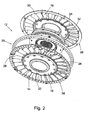
- each blade 10 is shown with corresponding segments 14 and 16. It should be understood, however, that the present invention is not limited to a one to one ratio between segments 14 and 16. That is, the blades 10 may be formed with different numbers of segments 14 and 16. For example, a certain number of vanes 16 may be formed with both the segments 14 and the segments 16, a different number of vanes excluding segments 14, and still another number of vanes with segments 16 alone.
- the segments 14 and 16 may be arranged in a variety of ways to form the blade 10.
- the segments are in contact with each other FIGS. 1 to 3
- the segments 14 and 16 contact each other along radial edges 22 and 24.
- one or both edges 22 and 24 are tapered in a wedge shape, as described below.
- Segments 14 and 16 include radial surfaces 26 and 28, and 30 and 32, respectively.
- corresponding radial surfaces of segments 14 and 16 at least partially overlap, as described below.
- the segments 14 and 16 are not circumferentially aligned, as described below.
- stators may be considered from the point of view of performance characteristics, including, but not limited to, torque ratio, efficiency, and performance.
- these characteristics are influenced by the blades of the stator, for example by the arrangement of the blades.
- corresponding arrangements of blades 10 and blade segments 14 and 16 can be selected.
- the arrangement of the blades and blade segments can be a axial alignment, radial alignment, or circumferential alignment.
- the orientation of the blades with respect to the expected direction of liquid flow in the stator.
- the stator 12 includes halves 36 and 38, for example, two axially separate halves as disclosed in commonly assigned U.S. Patent Application entitled “Integral Stator and One-Way Clutch” by George et al on the same day as the present invention.
- halves is meant that the structure of the stator, in particular the structure to which the blades are connected, is essentially formed by halves 36 and 38.
- the halves 36 and 38 may also be referred to as axial halves or axial terminations.
- the halves 36 and 38 are interconnected along a radial plane with respect to the axis 34.
- the halves are each formed from individual parts. That is, the halves are formed separately.
- the vane segments 14 are connected to the half 36, and the vane segments 16 are connected to the half 38.
- the segments are integral with the half 36 and the blade segments 16 are integral with the half 38.
- the segments 14 and half 36 are formed of one piece of material.
- the halves are connected together and fixed in the axial direction. That is, the halves are connected in any way with each other and do not move in the axial direction against each other. In some aspects, the halves are firmly connected. That is, the halves shift neither in the axial nor in the direction of rotation against each other. In some aspects, the halves are arranged to translate in the direction of rotation, as described below. In the FIGS. 1 to 4 are used to connect the halves fasteners 40 and 42. It should be understood, however, that other means may be used to join the halves, such as those described below, including, but not limited to, rivets, folded tongues, welds, adhesives, and beads.
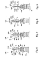
- FIGS. 6 to 9 FIG. 12 are partial cross-sectional views of stators with blades according to the present invention showing arrangements of respective stators and blades.
- FIG. The following description is in connection with the FIGS. 1 to 9 to see.
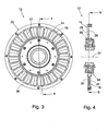
- the halves 36 and 38 are arranged to form part of a one-way clutch 44 described in commonly owned U.S. Patent Application entitled “Stator and One-Way Clutch Assembly for a Torque Converter" by Hemphill et al., filed on the same date as the present invention.
- the stators 12A-12D include a one-way clutch 44 having an inner race 46, rollers 48, and an outer race 50 with the halves 36 and 38 arranged to form axial terminations 52 and 54, respectively, of the clutch.
- the shutters 52 and 54 hold the races and the rollers of the clutch together in the axial direction.
- the use of other one-way clutches in the stators is within the spirit and scope of the claimed invention.
- the blades 10, segments 14 and 16, and halves 26 and 38 are not limited to any particular arrangement, shape, size, orientation or connection.
- the axial orientation refers to the radial line 58 (which is only in FIG Fig. 9 is shown, but also applies to the other figures), which goes in the axial direction through the center of the coupling 44.
- corresponding halves of the stators 12 are attached to the inner peripheral portion 62 and / or the outer peripheral portion 64.
- halves 36A / 38A and 36D / 38D are formed so that regions 62A and 62D are out of center in the axial direction.
- the halves 36A and 38A axially contact along the line 66 axially outward of the center. It follows that the axial dimension 68 is greater than the axial dimension 70, while maintaining a general axial alignment of the blades 10 on the line 58. This arrangement is useful for those aspects where it is desired to emphasize aspects of the front parts of the blades 10, for example to increase the area of the front part.
- the line 72 is substantially aligned with the line 58 in the axial direction, and the dimension 74 is also larger than the dimension 76, so that the front aspects of the blades 10 are more emphasized.
- FIGS. 7 and 8 the halves in the corresponding ring of the stator, that is, in the radial region in which the blades are located, are separated from each other in the axial direction.
- the ring 78 is for comparison in FIG Fig. 1 shown.
- the regions 62B and 64B and 62C and 64C are substantially aligned with the line 58 in the axial direction.
- An effect of the in the FIGS. 7 and 8 The arrangement shown is that the blade segments, for example 14B and 16C, are connected at such locations with the corresponding halves, which are located in the axial direction in the middle of the respective segments.
- the axial dimensions 80 and 82 are substantially the same for the segment 14B.
- the torque forces acting on the segments can be reduced by adjusting the distance between the connection points of the segments and corresponding edges of the segments, for example the distance 80 between the point 84 and the edge 86 of the segment 14B, is reduced.
- the segments 14C and 16C taper in the radial direction.
- an axial dimension 88 of the segment 14C near the region 64C is greater than near the region 62C.
- the dimension 88 near the region 62C may be greater than near the region 64C.
- any means known in the art may be used to connect the respective halves in the regions 64.
- the show FIGS. 6, 7 and 9 a folding joint, a tongue or a bead, while in Fig. 8 Rivets 90 are used.
- other means may be used, including but not limited to welds.
- FIGS. 10 to 17 FIG. 12 are plan views of blades according to the present invention showing various arrangements of the blades.
- FIG. The following description is in connection with the FIGS. 1 to 17 to see.
- Fig. 10 shows the blade 10 with the segments 14, and 16, which are connected to each other in the axial direction along the line 17.
- This arrangement corresponds to the representation in the FIGS. 1 to 5
- the FIGS. 11 and 12 show the segments 14 and 16, which are offset from each other over the circumference. From the FIGS. 11 and 12 It can be seen that the segment 16 can be displaced beyond the circumference of the segment 14 on any side. It should be understood that the offset may be related to the segment 16 as a reference.
- the bucket 10 is not on one limited amount of offset 100 between segments across the scope.
- FIGS. 13 and 14 show how the segments 14 and 16 are interconnected by an overlap.
- Fig. 13 shows a double overlap. That is, the portion 102 of the segment 14 and the portion 104 of the segment 16 are machined or deformed.
- Fig. 14 shows a simple overlap. That is, only the portion 106 of the segment 16 is machined or deformed. It should be clear that in the FIGS. 13 and 14 shown overlapping can be done in the opposite direction, for example, a simple overlap by machining the segment 14 can be formed.
- the blade 10 is not limited to any particular extent or arrangement of overlap.
- Fig. 15 shows segments 14 and 16 with wedge-beveled edges 108 and 110, respectively. It should be understood that other arrangements of segments may include wedge-shaped bevelled edges. For example, in the Figures 11 or 14 the segment 14 or 16 be tapered wedge-shaped. Furthermore, in Fig. 15 Other combinations of wedge-shaped beveled edges possible. For example, the edges 112 or 114 may be tapered in a wedge shape.
- the bucket 10 is not limited to a particular type of bevel or a particular combination of wedge-shaped bevelled edges.
- Fig. 16 shows a blade 10 with at least partially folded segments 14 and 16.
- the blade 10 is not limited to any particular type, degree, or arrangement of folding.
- dimensions 120 and 122 may be varied.
- only one of the segments 14 or 16 in the blade 10 may be folded while the other segment remains unfolded.
- Fig. 17 shows substantially teardrop-shaped segments, which are formed by casting or molding. Such segments may be cast in a variety of sizes, shapes, and configurations to produce surfaces 124 having, for example, a desired curvature and surface property.
- the in the FIGS. 11 and 12 set offset can be adjusted over the circumference.
- the setting may not be automatic.
- the adjustment is made automatically. That is, the stator 12 includes an automatic alignment member or adjuster for at least a portion of one or both halves 36 and 38.
- the adjuster controls the rotation of the halves (to change the offset of the segments 14 and 16 in the blades 10 circumferentially) in response to selected control parameters.
- the device is mechanical in nature, for example in the form of a resistive element, which provides "active" resistance to set a particular offset in the stator under certain operating conditions.
- a resistance element for example, a spring comes into question, wherein the degree of compression of the spring changes in response to the fluid pressure on the blades of the stator. For example, an increase in fluid pressure can cause the spring to compress.
- any resistance device known in the art can be used.
- an electromechanical alignment element is used.
- halves 36 and 38 connect electrical actuators or electromechanical devices that rotate the halves in response to control signals.
- the control signals may be generated by any means known in the art, including, but not limited to, sensors for measuring parameters in the stator, such as fluid pressure or fluid flow, or sensors for monitoring operational parameters Drive unit or a driven unit for a vehicle in which the stator is located.
- the blades 10, the segments 14 and 16 and the halves 36 and 38 are formed by stamping.
Landscapes
- Engineering & Computer Science (AREA)
- General Engineering & Computer Science (AREA)
- Mechanical Engineering (AREA)
- Structures Of Non-Positive Displacement Pumps (AREA)
- Iron Core Of Rotating Electric Machines (AREA)
- Turbine Rotor Nozzle Sealing (AREA)
- Manufacture Of Motors, Generators (AREA)
Applications Claiming Priority (2)
| Application Number | Priority Date | Filing Date | Title |
|---|---|---|---|
| US78573906P | 2006-03-24 | 2006-03-24 | |
| PCT/DE2007/000354 WO2007110019A1 (de) | 2006-03-24 | 2007-02-23 | Zweiteilige statorschaufel |
Publications (2)
| Publication Number | Publication Date |
|---|---|
| EP2002151A1 EP2002151A1 (de) | 2008-12-17 |
| EP2002151B1 true EP2002151B1 (de) | 2011-05-11 |
Family
ID=38042662
Family Applications (1)
| Application Number | Title | Priority Date | Filing Date |
|---|---|---|---|
| EP07711207A Not-in-force EP2002151B1 (de) | 2006-03-24 | 2007-02-23 | Zweiteilige statorschaufel |
Country Status (7)
| Country | Link |
|---|---|
| US (1) | US7850420B2 (enExample) |
| EP (1) | EP2002151B1 (enExample) |
| JP (1) | JP5286464B2 (enExample) |
| CN (1) | CN101410654B (enExample) |
| AT (1) | ATE509217T1 (enExample) |
| DE (1) | DE112007000496A5 (enExample) |
| WO (1) | WO2007110019A1 (enExample) |
Families Citing this family (25)
| Publication number | Priority date | Publication date | Assignee | Title |
|---|---|---|---|---|
| DE102007025407A1 (de) | 2006-06-13 | 2007-12-20 | Luk Lamellen Und Kupplungsbau Beteiligungs Kg | Reibungsgeführter Radialfreilauf |
| DE102007055146A1 (de) * | 2006-12-21 | 2008-06-26 | Luk Lamellen Und Kupplungsbau Beteiligungs Kg | Einkomponentenfreilauf |
| DE102008020681B4 (de) | 2007-05-09 | 2019-08-22 | Schaeffler Technologies AG & Co. KG | Dreiteilige Leitschaufel |
| DE102008020673B4 (de) * | 2007-05-09 | 2018-10-31 | Schaeffler Technologies AG & Co. KG | Abgestufte Statorschaufel |
| DE102008020678A1 (de) * | 2007-05-09 | 2008-11-13 | Luk Lamellen Und Kupplungsbau Beteiligungs Kg | Dreistrom Drehmomentwandler mit abgedichtetem Kolben und Zwangskühlströmung |
| DE102008032460A1 (de) * | 2007-07-31 | 2009-02-05 | Luk Lamellen Und Kupplungsbau Beteiligungs Kg | Drehmomentwandler mit Leitrad mit angegossener Seitenplatte |
| DE102008051107A1 (de) * | 2007-10-31 | 2009-05-07 | Luk Lamellen Und Kupplungsbau Beteiligungs Kg | Verbindungsstück für einen gestanzten Stator und einen Freilauf |
| DE102008058084A1 (de) | 2007-12-13 | 2009-06-25 | Luk Lamellen Und Kupplungsbau Beteiligungs Kg | Schaufelrad, insbesondere Leitrad für einen hydrodynamischen Drehzahl-/Drehmomentwandler und Verfahren zur Herstellung eines Schaufelrades |
| DE102009012075A1 (de) * | 2008-03-14 | 2009-09-17 | Luk Lamellen Und Kupplungsbau Beteiligungs Kg | Gestanzte Leitradanordnungen und Verfahren zur Montage gestanzter Leitradanordnungen |
| DE102010010609A1 (de) * | 2009-03-25 | 2010-10-07 | Luk Lamellen Und Kupplungsbau Beteiligungs Kg | Abgeschirmte gestanzte Leitradschaufel |
| DE102011011471A1 (de) | 2010-03-11 | 2011-09-15 | Schaeffler Technologies Gmbh & Co. Kg | Schaufelrad, hydrodynamische Komponente mit einem derartigen Schaufelrad und Verfahren zur Herstellung eines derartigen Schaufelrades |
| WO2011140412A1 (en) * | 2010-05-07 | 2011-11-10 | Flodesign Wind Turbine Corp. | Fluid turbine with moveable fluid control member |
| WO2012047665A2 (en) | 2010-09-27 | 2012-04-12 | Schaeffler Technologies Gmbh & Co. Kg | Stator centering plate |
| EP2725260B8 (en) | 2011-06-24 | 2017-08-02 | Honda Motor Co., Ltd. | Torque converter stator structure |
| US9046140B2 (en) * | 2012-10-18 | 2015-06-02 | Schaeffler Technologies AG & Co. KG | Conical wedge one-way clutch with split outer race |
| US20150037158A1 (en) * | 2013-07-30 | 2015-02-05 | Schaeffler Technologies Gmbh & Co. Kg | Torque converter with stamped stator |
| US10094223B2 (en) | 2014-03-13 | 2018-10-09 | Pratt & Whitney Canada Corp. | Integrated strut and IGV configuration |
| JP6537104B2 (ja) * | 2014-07-18 | 2019-07-03 | 株式会社エクセディ | 分割成形一体型ステータ |
| US10072746B2 (en) * | 2015-05-05 | 2018-09-11 | Valeo Embrayages | Stator assembly of hydrokinetic torque converter, and method for making the same |
| JP2018189198A (ja) * | 2017-05-10 | 2018-11-29 | 株式会社エクセディ | ステータ |
| US10830349B2 (en) * | 2018-08-21 | 2020-11-10 | Ford Global Technologies, Llc | Variable pitch stator structure with all blades free to rotate and torque converter with variable pitch stator |
| US10895310B2 (en) * | 2018-08-23 | 2021-01-19 | Schaeffler Technologies AG & Co. KG | Side plate to stator attachment for torque converter |
| CN112576724B (zh) * | 2021-01-08 | 2022-03-18 | 吉林大学 | 一种带有仿生缝隙的能容可调式液力变矩器 |
| CN112943700B (zh) * | 2021-02-25 | 2022-09-27 | 上海汽车集团股份有限公司 | 一种发动机及其离心式压气机、叶片扩压器 |
| US12215766B1 (en) * | 2024-02-22 | 2025-02-04 | Schaeffler Technologies AG & Co. KG | Modular torque converter stator with cammed blades |
Family Cites Families (22)
| Publication number | Priority date | Publication date | Assignee | Title |
|---|---|---|---|---|
| US2588668A (en) * | 1949-02-23 | 1952-03-11 | Chrysler Corp | Fluid coupling mounting |
| US2755628A (en) * | 1951-05-22 | 1956-07-24 | Borg Warner | Hydraulic torque converter |
| DE1193758B (de) * | 1957-11-23 | 1965-05-26 | Eta Corp G M B H | Mehrstufiger, hydrodynamischer Drehmomentenwandler mit dreieckfoermigem Querschnitt nach dem Foettinger Prinzip |
| US3014430A (en) * | 1958-05-19 | 1961-12-26 | Schneider Brothers Company | Hydraulic torque converter |
| US3244400A (en) * | 1964-10-30 | 1966-04-05 | Saunders Walter Selden | Extended range cascade for torque converters and turbo-machinery |
| US3385060A (en) * | 1966-05-02 | 1968-05-28 | Ford Motor Co | Hydrokinetic torque converter mechanism with multiple section reactor blades |
| US3354643A (en) * | 1966-05-18 | 1967-11-28 | Ford Motor Co | Hydrokinetic torque converter mechanism with variable geometry stator blading |
| US3572034A (en) * | 1969-11-21 | 1971-03-23 | Ford Motor Co | Fabricated two-piece stator assembly for hydrokinetic torque converters |
| DE2905738A1 (de) * | 1979-02-15 | 1980-08-28 | Daimler Benz Ag | Leitrad eines hydrodynamischen drehmomentwandlers |
| JPS6164558U (enExample) * | 1984-10-02 | 1986-05-01 | ||
| DE3702548A1 (de) * | 1987-01-29 | 1988-08-11 | Ford Werke Ag | Hydrodynamischer drehmomentwandler, insbesondere fuer kraftfahrzeuge |
| DE3931427A1 (de) * | 1988-10-11 | 1990-04-12 | Luk Lamellen & Kupplungsbau | Fluessigkeitskupplung, wie foettinger-kupplung oder drehmomentwandler |
| US5307629A (en) * | 1992-09-21 | 1994-05-03 | General Motors Corporation | Variable pitch stator with passive control |
| JP3582134B2 (ja) * | 1995-03-17 | 2004-10-27 | マツダ株式会社 | トルクコンバータの翼形状設計方法および同設計装置 |
| JPH0942413A (ja) * | 1995-07-31 | 1997-02-14 | Aisin Seiki Co Ltd | ブレード部材およびその成形方法 |
| JP3028499B2 (ja) * | 1995-08-02 | 2000-04-04 | 勝彦 松波 | トルクコンバータの調整方法 |
| JP3539649B2 (ja) * | 1995-10-01 | 2004-07-07 | 株式会社豊田中央研究所 | トルクコンバータ用羽根車 |
| KR100496764B1 (ko) | 2002-08-30 | 2005-06-23 | 한국파워트레인 주식회사 | 토크 컨버터의 고정자의 날개 |
| JP2006038054A (ja) * | 2004-07-26 | 2006-02-09 | Yutaka Giken Co Ltd | 流体伝動装置の羽根車 |
| US7770707B2 (en) | 2005-08-24 | 2010-08-10 | Luk Lamellen Und Kupplungsbau Beteiligungs Kg | Axially engaging and disengaging one-way clutch and a stator having an axially engaging and disengaging one-way clutch |
| JP2009520160A (ja) | 2005-12-19 | 2009-05-21 | ルーク ラメレン ウント クツプルングスバウ ベタイリグングス コマンディートゲゼルシャフト | トルクコンバータに用いられるステータサイドプレート |
| US7854588B2 (en) | 2005-12-20 | 2010-12-21 | Schaeffler Technologies Gmbh & Co. Kg | Stamped torque converter stator blades and a torque converter stator with stamped blades |
-
2007
- 2007-02-23 JP JP2009501831A patent/JP5286464B2/ja not_active Expired - Fee Related
- 2007-02-23 WO PCT/DE2007/000354 patent/WO2007110019A1/de not_active Ceased
- 2007-02-23 AT AT07711207T patent/ATE509217T1/de active
- 2007-02-23 EP EP07711207A patent/EP2002151B1/de not_active Not-in-force
- 2007-02-23 DE DE112007000496T patent/DE112007000496A5/de not_active Withdrawn
- 2007-02-23 CN CN2007800106057A patent/CN101410654B/zh not_active Expired - Fee Related
- 2007-03-23 US US11/728,066 patent/US7850420B2/en not_active Expired - Fee Related
Also Published As
| Publication number | Publication date |
|---|---|
| WO2007110019A1 (de) | 2007-10-04 |
| EP2002151A1 (de) | 2008-12-17 |
| JP2009531605A (ja) | 2009-09-03 |
| CN101410654A (zh) | 2009-04-15 |
| US20070224042A1 (en) | 2007-09-27 |
| US7850420B2 (en) | 2010-12-14 |
| ATE509217T1 (de) | 2011-05-15 |
| JP5286464B2 (ja) | 2013-09-11 |
| DE112007000496A5 (de) | 2008-11-27 |
| CN101410654B (zh) | 2012-03-21 |
Similar Documents
| Publication | Publication Date | Title |
|---|---|---|
| EP2002151B1 (de) | Zweiteilige statorschaufel | |
| WO2008043600A1 (de) | Kupplungsvorrichtung | |
| DE112017000866T5 (de) | Zentrifugalgebläserad für HLKK-Anwendungen | |
| DE102009040504A1 (de) | Beschlag für einen Fahrzeugsitz | |
| DE10058935B4 (de) | Vorrichtung zur Befestigung einer Ventilatorschraube an einer Antriebswelle | |
| DE3044415A1 (de) | Elastische kupplung zum uebertragen einer drehbewegung | |
| DE102019113236A1 (de) | Elektromotor und Läufer davon | |
| EP2229541B1 (de) | Drehmomentübertragungsvorrichtung eines kraftfahrzeugs | |
| DE19710918B9 (de) | Verfahren zur Herstellung einer Zusatzmasse für eine Schwungmassenvorrichtung und Schwungmassenvorrichtung mit einer derart hergestellten Zusatzmasse | |
| DE102007058019A1 (de) | Axialer Freilauf mit axialem Abstandselement | |
| DE2544379C3 (de) | Gebläserotor für ein Querstromgebläse | |
| DE102015213725A1 (de) | Aus Segmenten zusammengesetzter Planetenträger | |
| WO2021219497A1 (de) | Welle, umformwerkzeug, herstellungsverfahren und rotor für eine elektrische maschine | |
| DE102007042835A1 (de) | Verbindung eines Drehelementes mit einer Nabe | |
| DE102008008864A1 (de) | Überbrückungsvorrichtung und mit einer solchen ausgestattete hydraulische Drehmomentübertragungsvorrichtung | |
| DE102018106575A1 (de) | Kugel- und kugelschalengelenk-baugruppe mit einer rückhaltevorrichtung | |
| EP3375272B1 (de) | Packerwalze zur bodenbearbeitung | |
| EP1801459A1 (de) | Schaufel und Schaufelbaugruppe für den Stator eines Drehmomentwandlers, Stator mit Schaufeln für einen Drehmomentwandler, und Verfahren zu deren Herstellung | |
| EP1431604B1 (de) | Kreuzgelenk mit einem Sicherungselement | |
| DE19539814A1 (de) | Hydrodynamischer Drehmomentwandler mit Stabilisierungsring an den Schaufelrädern | |
| EP3523547A1 (de) | Tripodenrolle für ein gleichlaufgelenk mit sicherungsbereich, gleichlaufgelenk mit der tripodenrolle sowie verfahren zum montieren der tripodenrolle | |
| DE3606073A1 (de) | Drehgelenk | |
| DE102016216704A1 (de) | Wellenkupplung | |
| DE102016123580A1 (de) | Rotorteil eines Rotors für einen Nockenwellenversteller und Presswerkzeug zu dessen Herstellung | |
| EP0939238A2 (de) | Elastische Wellenkupplung |
Legal Events
| Date | Code | Title | Description |
|---|---|---|---|
| PUAI | Public reference made under article 153(3) epc to a published international application that has entered the european phase |
Free format text: ORIGINAL CODE: 0009012 |
|
| 17P | Request for examination filed |
Effective date: 20081024 |
|
| AK | Designated contracting states |
Kind code of ref document: A1 Designated state(s): AT BE BG CH CY CZ DE DK EE ES FI FR GB GR HU IE IS IT LI LT LU LV MC NL PL PT RO SE SI SK TR |
|
| 17Q | First examination report despatched |
Effective date: 20091007 |
|
| RAP1 | Party data changed (applicant data changed or rights of an application transferred) |
Owner name: SCHAEFFLER TECHNOLOGIES GMBH & CO. KG |
|
| RIC1 | Information provided on ipc code assigned before grant |
Ipc: F16H 41/28 20060101AFI20101119BHEP Ipc: F16H 41/26 20060101ALI20101119BHEP |
|
| GRAP | Despatch of communication of intention to grant a patent |
Free format text: ORIGINAL CODE: EPIDOSNIGR1 |
|
| DAX | Request for extension of the european patent (deleted) | ||
| GRAS | Grant fee paid |
Free format text: ORIGINAL CODE: EPIDOSNIGR3 |
|
| GRAA | (expected) grant |
Free format text: ORIGINAL CODE: 0009210 |
|
| AK | Designated contracting states |
Kind code of ref document: B1 Designated state(s): AT BE BG CH CY CZ DE DK EE ES FI FR GB GR HU IE IS IT LI LT LU LV MC NL PL PT RO SE SI SK TR |
|
| REG | Reference to a national code |
Ref country code: GB Ref legal event code: FG4D Free format text: NOT ENGLISH |
|
| REG | Reference to a national code |
Ref country code: CH Ref legal event code: EP |
|
| REG | Reference to a national code |
Ref country code: IE Ref legal event code: FG4D |
|
| REG | Reference to a national code |
Ref country code: DE Ref legal event code: R096 Ref document number: 502007007174 Country of ref document: DE Effective date: 20110622 |
|
| REG | Reference to a national code |
Ref country code: NL Ref legal event code: VDEP Effective date: 20110511 |
|
| PG25 | Lapsed in a contracting state [announced via postgrant information from national office to epo] |
Ref country code: LT Free format text: LAPSE BECAUSE OF FAILURE TO SUBMIT A TRANSLATION OF THE DESCRIPTION OR TO PAY THE FEE WITHIN THE PRESCRIBED TIME-LIMIT Effective date: 20110511 Ref country code: SE Free format text: LAPSE BECAUSE OF FAILURE TO SUBMIT A TRANSLATION OF THE DESCRIPTION OR TO PAY THE FEE WITHIN THE PRESCRIBED TIME-LIMIT Effective date: 20110511 Ref country code: PT Free format text: LAPSE BECAUSE OF FAILURE TO SUBMIT A TRANSLATION OF THE DESCRIPTION OR TO PAY THE FEE WITHIN THE PRESCRIBED TIME-LIMIT Effective date: 20110912 |
|
| PG25 | Lapsed in a contracting state [announced via postgrant information from national office to epo] |
Ref country code: SI Free format text: LAPSE BECAUSE OF FAILURE TO SUBMIT A TRANSLATION OF THE DESCRIPTION OR TO PAY THE FEE WITHIN THE PRESCRIBED TIME-LIMIT Effective date: 20110511 Ref country code: FI Free format text: LAPSE BECAUSE OF FAILURE TO SUBMIT A TRANSLATION OF THE DESCRIPTION OR TO PAY THE FEE WITHIN THE PRESCRIBED TIME-LIMIT Effective date: 20110511 Ref country code: ES Free format text: LAPSE BECAUSE OF FAILURE TO SUBMIT A TRANSLATION OF THE DESCRIPTION OR TO PAY THE FEE WITHIN THE PRESCRIBED TIME-LIMIT Effective date: 20110822 Ref country code: IS Free format text: LAPSE BECAUSE OF FAILURE TO SUBMIT A TRANSLATION OF THE DESCRIPTION OR TO PAY THE FEE WITHIN THE PRESCRIBED TIME-LIMIT Effective date: 20110911 Ref country code: GR Free format text: LAPSE BECAUSE OF FAILURE TO SUBMIT A TRANSLATION OF THE DESCRIPTION OR TO PAY THE FEE WITHIN THE PRESCRIBED TIME-LIMIT Effective date: 20110812 Ref country code: LV Free format text: LAPSE BECAUSE OF FAILURE TO SUBMIT A TRANSLATION OF THE DESCRIPTION OR TO PAY THE FEE WITHIN THE PRESCRIBED TIME-LIMIT Effective date: 20110511 Ref country code: CY Free format text: LAPSE BECAUSE OF FAILURE TO SUBMIT A TRANSLATION OF THE DESCRIPTION OR TO PAY THE FEE WITHIN THE PRESCRIBED TIME-LIMIT Effective date: 20110511 |
|
| REG | Reference to a national code |
Ref country code: IE Ref legal event code: FD4D |
|
| PG25 | Lapsed in a contracting state [announced via postgrant information from national office to epo] |
Ref country code: NL Free format text: LAPSE BECAUSE OF FAILURE TO SUBMIT A TRANSLATION OF THE DESCRIPTION OR TO PAY THE FEE WITHIN THE PRESCRIBED TIME-LIMIT Effective date: 20110511 |
|
| PG25 | Lapsed in a contracting state [announced via postgrant information from national office to epo] |
Ref country code: IE Free format text: LAPSE BECAUSE OF FAILURE TO SUBMIT A TRANSLATION OF THE DESCRIPTION OR TO PAY THE FEE WITHIN THE PRESCRIBED TIME-LIMIT Effective date: 20110511 Ref country code: EE Free format text: LAPSE BECAUSE OF FAILURE TO SUBMIT A TRANSLATION OF THE DESCRIPTION OR TO PAY THE FEE WITHIN THE PRESCRIBED TIME-LIMIT Effective date: 20110511 Ref country code: CZ Free format text: LAPSE BECAUSE OF FAILURE TO SUBMIT A TRANSLATION OF THE DESCRIPTION OR TO PAY THE FEE WITHIN THE PRESCRIBED TIME-LIMIT Effective date: 20110511 |
|
| PG25 | Lapsed in a contracting state [announced via postgrant information from national office to epo] |
Ref country code: DK Free format text: LAPSE BECAUSE OF FAILURE TO SUBMIT A TRANSLATION OF THE DESCRIPTION OR TO PAY THE FEE WITHIN THE PRESCRIBED TIME-LIMIT Effective date: 20110511 Ref country code: RO Free format text: LAPSE BECAUSE OF FAILURE TO SUBMIT A TRANSLATION OF THE DESCRIPTION OR TO PAY THE FEE WITHIN THE PRESCRIBED TIME-LIMIT Effective date: 20110511 Ref country code: PL Free format text: LAPSE BECAUSE OF FAILURE TO SUBMIT A TRANSLATION OF THE DESCRIPTION OR TO PAY THE FEE WITHIN THE PRESCRIBED TIME-LIMIT Effective date: 20110511 Ref country code: SK Free format text: LAPSE BECAUSE OF FAILURE TO SUBMIT A TRANSLATION OF THE DESCRIPTION OR TO PAY THE FEE WITHIN THE PRESCRIBED TIME-LIMIT Effective date: 20110511 |
|
| RAP2 | Party data changed (patent owner data changed or rights of a patent transferred) |
Owner name: SCHAEFFLER TECHNOLOGIES AG & CO. KG |
|
| REG | Reference to a national code |
Ref country code: CH Ref legal event code: PFA Owner name: SCHAEFFLER TECHNOLOGIES AG & CO. KG Free format text: SCHAEFFLER TECHNOLOGIES GMBH & CO. KG#INDUSTRIESTRASSE 1-3#91074 HERZOGENAURACH (DE) -TRANSFER TO- SCHAEFFLER TECHNOLOGIES AG & CO. KG#INDUSTRIESTRASSE 1-3#91074 HERZOGENAURACH (DE) |
|
| PLBE | No opposition filed within time limit |
Free format text: ORIGINAL CODE: 0009261 |
|
| STAA | Information on the status of an ep patent application or granted ep patent |
Free format text: STATUS: NO OPPOSITION FILED WITHIN TIME LIMIT |
|
| 26N | No opposition filed |
Effective date: 20120214 |
|
| PG25 | Lapsed in a contracting state [announced via postgrant information from national office to epo] |
Ref country code: IT Free format text: LAPSE BECAUSE OF FAILURE TO SUBMIT A TRANSLATION OF THE DESCRIPTION OR TO PAY THE FEE WITHIN THE PRESCRIBED TIME-LIMIT Effective date: 20110511 |
|
| REG | Reference to a national code |
Ref country code: DE Ref legal event code: R097 Ref document number: 502007007174 Country of ref document: DE Effective date: 20120214 |
|
| BERE | Be: lapsed |
Owner name: SCHAEFFLER TECHNOLOGIES G.M.B.H. & CO. KG Effective date: 20120228 |
|
| PG25 | Lapsed in a contracting state [announced via postgrant information from national office to epo] |
Ref country code: MC Free format text: LAPSE BECAUSE OF NON-PAYMENT OF DUE FEES Effective date: 20120229 |
|
| REG | Reference to a national code |
Ref country code: CH Ref legal event code: PL |
|
| REG | Reference to a national code |
Ref country code: DE Ref legal event code: R081 Ref document number: 502007007174 Country of ref document: DE Owner name: SCHAEFFLER TECHNOLOGIES AG & CO. KG, DE Free format text: FORMER OWNER: SCHAEFFLER TECHNOLOGIES GMBH & CO. KG, 91074 HERZOGENAURACH, DE Effective date: 20120828 Ref country code: DE Ref legal event code: R081 Ref document number: 502007007174 Country of ref document: DE Owner name: SCHAEFFLER TECHNOLOGIES GMBH & CO. KG, DE Free format text: FORMER OWNER: SCHAEFFLER TECHNOLOGIES GMBH & CO. KG, 91074 HERZOGENAURACH, DE Effective date: 20120828 |
|
| GBPC | Gb: european patent ceased through non-payment of renewal fee |
Effective date: 20120223 |
|
| PG25 | Lapsed in a contracting state [announced via postgrant information from national office to epo] |
Ref country code: LI Free format text: LAPSE BECAUSE OF NON-PAYMENT OF DUE FEES Effective date: 20120229 Ref country code: CH Free format text: LAPSE BECAUSE OF NON-PAYMENT OF DUE FEES Effective date: 20120229 |
|
| PG25 | Lapsed in a contracting state [announced via postgrant information from national office to epo] |
Ref country code: BE Free format text: LAPSE BECAUSE OF NON-PAYMENT OF DUE FEES Effective date: 20120228 |
|
| PG25 | Lapsed in a contracting state [announced via postgrant information from national office to epo] |
Ref country code: GB Free format text: LAPSE BECAUSE OF NON-PAYMENT OF DUE FEES Effective date: 20120223 |
|
| REG | Reference to a national code |
Ref country code: AT Ref legal event code: MM01 Ref document number: 509217 Country of ref document: AT Kind code of ref document: T Effective date: 20120223 |
|
| PG25 | Lapsed in a contracting state [announced via postgrant information from national office to epo] |
Ref country code: AT Free format text: LAPSE BECAUSE OF NON-PAYMENT OF DUE FEES Effective date: 20120223 Ref country code: BG Free format text: LAPSE BECAUSE OF FAILURE TO SUBMIT A TRANSLATION OF THE DESCRIPTION OR TO PAY THE FEE WITHIN THE PRESCRIBED TIME-LIMIT Effective date: 20110811 |
|
| REG | Reference to a national code |
Ref country code: DE Ref legal event code: R081 Ref document number: 502007007174 Country of ref document: DE Owner name: SCHAEFFLER TECHNOLOGIES GMBH & CO. KG, DE Free format text: FORMER OWNER: SCHAEFFLER TECHNOLOGIES AG & CO. KG, 91074 HERZOGENAURACH, DE Effective date: 20140212 Ref country code: DE Ref legal event code: R081 Ref document number: 502007007174 Country of ref document: DE Owner name: SCHAEFFLER TECHNOLOGIES AG & CO. KG, DE Free format text: FORMER OWNER: SCHAEFFLER TECHNOLOGIES AG & CO. KG, 91074 HERZOGENAURACH, DE Effective date: 20140212 |
|
| PG25 | Lapsed in a contracting state [announced via postgrant information from national office to epo] |
Ref country code: TR Free format text: LAPSE BECAUSE OF FAILURE TO SUBMIT A TRANSLATION OF THE DESCRIPTION OR TO PAY THE FEE WITHIN THE PRESCRIBED TIME-LIMIT Effective date: 20110511 |
|
| PG25 | Lapsed in a contracting state [announced via postgrant information from national office to epo] |
Ref country code: LU Free format text: LAPSE BECAUSE OF NON-PAYMENT OF DUE FEES Effective date: 20120223 |
|
| PG25 | Lapsed in a contracting state [announced via postgrant information from national office to epo] |
Ref country code: HU Free format text: LAPSE BECAUSE OF FAILURE TO SUBMIT A TRANSLATION OF THE DESCRIPTION OR TO PAY THE FEE WITHIN THE PRESCRIBED TIME-LIMIT Effective date: 20070223 |
|
| REG | Reference to a national code |
Ref country code: DE Ref legal event code: R081 Ref document number: 502007007174 Country of ref document: DE Owner name: SCHAEFFLER TECHNOLOGIES AG & CO. KG, DE Free format text: FORMER OWNER: SCHAEFFLER TECHNOLOGIES GMBH & CO. KG, 91074 HERZOGENAURACH, DE Effective date: 20150127 |
|
| REG | Reference to a national code |
Ref country code: FR Ref legal event code: PLFP Year of fee payment: 10 |
|
| REG | Reference to a national code |
Ref country code: FR Ref legal event code: PLFP Year of fee payment: 11 |
|
| REG | Reference to a national code |
Ref country code: FR Ref legal event code: PLFP Year of fee payment: 12 |
|
| PGFP | Annual fee paid to national office [announced via postgrant information from national office to epo] |
Ref country code: DE Payment date: 20200429 Year of fee payment: 14 |
|
| REG | Reference to a national code |
Ref country code: DE Ref legal event code: R119 Ref document number: 502007007174 Country of ref document: DE |
|
| PG25 | Lapsed in a contracting state [announced via postgrant information from national office to epo] |
Ref country code: DE Free format text: LAPSE BECAUSE OF NON-PAYMENT OF DUE FEES Effective date: 20210901 |
|
| PGFP | Annual fee paid to national office [announced via postgrant information from national office to epo] |
Ref country code: FR Payment date: 20220217 Year of fee payment: 16 |
|
| P01 | Opt-out of the competence of the unified patent court (upc) registered |
Effective date: 20230522 |
|
| PG25 | Lapsed in a contracting state [announced via postgrant information from national office to epo] |
Ref country code: FR Free format text: LAPSE BECAUSE OF NON-PAYMENT OF DUE FEES Effective date: 20230228 |