EP2002151B1 - Two-piece stator blade - Google Patents
Two-piece stator blade Download PDFInfo
- Publication number
- EP2002151B1 EP2002151B1 EP07711207A EP07711207A EP2002151B1 EP 2002151 B1 EP2002151 B1 EP 2002151B1 EP 07711207 A EP07711207 A EP 07711207A EP 07711207 A EP07711207 A EP 07711207A EP 2002151 B1 EP2002151 B1 EP 2002151B1
- Authority
- EP
- European Patent Office
- Prior art keywords
- blade
- stator
- segment
- axial
- blade according
- Prior art date
- Legal status (The legal status is an assumption and is not a legal conclusion. Google has not performed a legal analysis and makes no representation as to the accuracy of the status listed.)
- Not-in-force
Links
Images


Classifications
-
- F—MECHANICAL ENGINEERING; LIGHTING; HEATING; WEAPONS; BLASTING
- F16—ENGINEERING ELEMENTS AND UNITS; GENERAL MEASURES FOR PRODUCING AND MAINTAINING EFFECTIVE FUNCTIONING OF MACHINES OR INSTALLATIONS; THERMAL INSULATION IN GENERAL
- F16H—GEARING
- F16H41/00—Rotary fluid gearing of the hydrokinetic type
- F16H41/24—Details
- F16H41/26—Shape of runner blades or channels with respect to function
-
- F—MECHANICAL ENGINEERING; LIGHTING; HEATING; WEAPONS; BLASTING
- F04—POSITIVE - DISPLACEMENT MACHINES FOR LIQUIDS; PUMPS FOR LIQUIDS OR ELASTIC FLUIDS
- F04D—NON-POSITIVE-DISPLACEMENT PUMPS
- F04D29/00—Details, component parts, or accessories
- F04D29/40—Casings; Connections of working fluid
- F04D29/52—Casings; Connections of working fluid for axial pumps
- F04D29/54—Fluid-guiding means, e.g. diffusers
- F04D29/541—Specially adapted for elastic fluid pumps
- F04D29/542—Bladed diffusers
-
- F—MECHANICAL ENGINEERING; LIGHTING; HEATING; WEAPONS; BLASTING
- F16—ENGINEERING ELEMENTS AND UNITS; GENERAL MEASURES FOR PRODUCING AND MAINTAINING EFFECTIVE FUNCTIONING OF MACHINES OR INSTALLATIONS; THERMAL INSULATION IN GENERAL
- F16H—GEARING
- F16H41/00—Rotary fluid gearing of the hydrokinetic type
- F16H41/24—Details
- F16H41/28—Details with respect to manufacture, e.g. blade attachment
Definitions
- the invention relates to improvements in a device for transmitting power between a rotary drive unit (for example the motor of a motor vehicle) and a rotationally driven unit (for example the automatic transmission in the motor vehicle).
- a rotary drive unit for example the motor of a motor vehicle
- a rotationally driven unit for example the automatic transmission in the motor vehicle.
- the invention relates to a stator blade with two separately formed axial segments for a torque converter.
- the stator has stamped axial halves, and the segments are formed as an integral part of the respective halves.
- One-piece blades in stators are known.
- Two-part stator blades are also known, as described, for example, in US patent application no. US 2004/0 237 516 A1 (Shin) or in the published patent application DE 39 31 427 A1 to be discribed.
- the blade segments of Shin are separated from each other in the radial direction. That is, one segment is connected to an outer periphery of the stator, and the other segment is connected to an inner circumference of the stator.
- the influence on the liquid flow through the blades is essentially limited to the flow along radial planes.
- the publication DE 39 31 427 A1 shows the arrangement of two axially adjacent stators, wherein between the stators axially a gap is formed.
- the present invention generally includes a stator blade in a torque converter having a first blade segment connected to inner and outer circumferential portions of the stator and a second formed separately from the first blade segment and connected to the inner and outer circumferential portions Bucket segment includes.
- the first and second blade segments are in contact, the first and second blade segments include corresponding edges, and the first and second blade segments contact each other at the respective edges, or at least one of the corresponding first edges is tapered in a wedge shape.
- the first and second blade segments include respective surfaces, and the corresponding surfaces at least partially overlap, or the first and second blade segments are offset from one another circumferentially.
- the first or second blade segments are at least partially folded and the blade is stamped.
- the stator includes performance characteristics
- the first and second vane segments are located in respective arrays, and the corresponding arrays are selected to vary the performance characteristics.
- performance characteristics such as torque ratio, efficiency, and performance, among others, become Other arrangements such as an axial arrangement, a radial arrangement and an arrangement arranged across the circumference.
- first and second blade segments are circumferentially aligned, and the stator includes an alignment member that is operatively arranged to control alignment about the circumference.
- the torque converter includes a fluid, and the alignment member is arranged to control alignment in response to the pressure of the fluid on the blade.
- the stator includes a first axial half and a second axial half, the first and second axial halves are formed separately and fixedly connected together, the first vane segment is connected to the first axial half, and the second vane segment is connected to the first axial half second axiaien half connected.
- first vane segment is formed as an integral part of the first axial half
- second vane segment is formed as an integral part of the second axial half.
- the present invention generally includes a stator for a stator in a torque converter including a first vane segment formed integrally with the inner and outer peripheral portions of the stator and including a second vane segment separate from the first vane segment Blade segment and formed as an integral part together with the inner and outer peripheral portions.
- the present invention generally includes a stator for a stator in a torque converter including a first vane segment integrally formed with a first axial half of the stator and connected to first inner and outer peripheral portions of the first axial half, and which includes a second vane segment formed separately from the first vane segment and integral with a second axial half of the stator and connected to second inner and outer peripheral portions of the second axial half.
- the first and second axial halves are formed separately from each other and firmly connected.
- a general object of the present invention is to provide a blade for a stator that can be formed in a wide variety of arrangements.
- Another object of the present invention is to provide a blade for a stator that can be formed from axially separated segments.
- Yet another object of the present invention is to provide a multi-segment blade for a variable pitch stator between the segments.
- FIG. 12 is a perspective view of a cylindrical coordinate system 280 illustrating the spatial notation used in the present patent application.
- the present invention will be described, at least in part, in connection with a cylindrical coordinate system.
- the system 280 has a longitudinal axis 281 which serves as a reference for the following spatial and directional designations.
- the adjectives "axial,”"radial,” and “circumferential” refer to an orientation parallel to axis 281, a radius 282 (which is perpendicular to axis 281), and a circumference 283, respectively.
- the adjectives "axial,”"radial,” and “ Circumferential also concern alignment parallel to corresponding planes.
- the objects 284, 285 and 286 serve to clarify the arrangement of the different planes.
- the surface 287 of the object 284 forms an axial plane. That is, the axis 281 forms a line along the surface.
- the surface 288 of the object 285 forms a radial plane. That is, the radius 282 is along a line the area.
- the surface 289 of the object 286 forms a peripheral surface. That is, the periphery 283 forms a line along the surface.
- an axial displacement or arrangement parallel to the axis 281 occurs, that a radial displacement or arrangement is parallel to the radius 282 and that a displacement or arrangement on the circumference takes place parallel to the circumference 283.
- a rotation takes place about the axis 281.
- adverbs "axial,” “radial,” and “circumferential” refer to an orientation parallel to axis 281, radius 282, and circumference 284, respectively.
- the adverbs "axial,” “radial,” and “circumference” also refer to one corresponding levels parallel alignment.
- each blade 10 is shown with corresponding segments 14 and 16. It should be understood, however, that the present invention is not limited to a one to one ratio between segments 14 and 16. That is, the blades 10 may be formed with different numbers of segments 14 and 16. For example, a certain number of vanes 16 may be formed with both the segments 14 and the segments 16, a different number of vanes excluding segments 14, and still another number of vanes with segments 16 alone.
- the segments 14 and 16 may be arranged in a variety of ways to form the blade 10.
- the segments are in contact with each other FIGS. 1 to 3
- the segments 14 and 16 contact each other along radial edges 22 and 24.
- one or both edges 22 and 24 are tapered in a wedge shape, as described below.
- Segments 14 and 16 include radial surfaces 26 and 28, and 30 and 32, respectively.
- corresponding radial surfaces of segments 14 and 16 at least partially overlap, as described below.
- the segments 14 and 16 are not circumferentially aligned, as described below.
- stators may be considered from the point of view of performance characteristics, including, but not limited to, torque ratio, efficiency, and performance.
- these characteristics are influenced by the blades of the stator, for example by the arrangement of the blades.
- corresponding arrangements of blades 10 and blade segments 14 and 16 can be selected.
- the arrangement of the blades and blade segments can be a axial alignment, radial alignment, or circumferential alignment.
- the orientation of the blades with respect to the expected direction of liquid flow in the stator.
- the stator 12 includes halves 36 and 38, for example, two axially separate halves as disclosed in commonly assigned U.S. Patent Application entitled “Integral Stator and One-Way Clutch” by George et al on the same day as the present invention.
- halves is meant that the structure of the stator, in particular the structure to which the blades are connected, is essentially formed by halves 36 and 38.
- the halves 36 and 38 may also be referred to as axial halves or axial terminations.
- the halves 36 and 38 are interconnected along a radial plane with respect to the axis 34.
- the halves are each formed from individual parts. That is, the halves are formed separately.
- the vane segments 14 are connected to the half 36, and the vane segments 16 are connected to the half 38.
- the segments are integral with the half 36 and the blade segments 16 are integral with the half 38.
- the segments 14 and half 36 are formed of one piece of material.
- the halves are connected together and fixed in the axial direction. That is, the halves are connected in any way with each other and do not move in the axial direction against each other. In some aspects, the halves are firmly connected. That is, the halves shift neither in the axial nor in the direction of rotation against each other. In some aspects, the halves are arranged to translate in the direction of rotation, as described below. In the FIGS. 1 to 4 are used to connect the halves fasteners 40 and 42. It should be understood, however, that other means may be used to join the halves, such as those described below, including, but not limited to, rivets, folded tongues, welds, adhesives, and beads.
- FIGS. 6 to 9 FIG. 12 are partial cross-sectional views of stators with blades according to the present invention showing arrangements of respective stators and blades.
- FIG. The following description is in connection with the FIGS. 1 to 9 to see.
- the halves 36 and 38 are arranged to form part of a one-way clutch 44 described in commonly owned U.S. Patent Application entitled “Stator and One-Way Clutch Assembly for a Torque Converter" by Hemphill et al., filed on the same date as the present invention.
- the stators 12A-12D include a one-way clutch 44 having an inner race 46, rollers 48, and an outer race 50 with the halves 36 and 38 arranged to form axial terminations 52 and 54, respectively, of the clutch.
- the shutters 52 and 54 hold the races and the rollers of the clutch together in the axial direction.
- the use of other one-way clutches in the stators is within the spirit and scope of the claimed invention.
- the blades 10, segments 14 and 16, and halves 26 and 38 are not limited to any particular arrangement, shape, size, orientation or connection.
- the axial orientation refers to the radial line 58 (which is only in FIG Fig. 9 is shown, but also applies to the other figures), which goes in the axial direction through the center of the coupling 44.
- corresponding halves of the stators 12 are attached to the inner peripheral portion 62 and / or the outer peripheral portion 64.
- halves 36A / 38A and 36D / 38D are formed so that regions 62A and 62D are out of center in the axial direction.
- the halves 36A and 38A axially contact along the line 66 axially outward of the center. It follows that the axial dimension 68 is greater than the axial dimension 70, while maintaining a general axial alignment of the blades 10 on the line 58. This arrangement is useful for those aspects where it is desired to emphasize aspects of the front parts of the blades 10, for example to increase the area of the front part.
- the line 72 is substantially aligned with the line 58 in the axial direction, and the dimension 74 is also larger than the dimension 76, so that the front aspects of the blades 10 are more emphasized.
- FIGS. 7 and 8 the halves in the corresponding ring of the stator, that is, in the radial region in which the blades are located, are separated from each other in the axial direction.
- the ring 78 is for comparison in FIG Fig. 1 shown.
- the regions 62B and 64B and 62C and 64C are substantially aligned with the line 58 in the axial direction.
- An effect of the in the FIGS. 7 and 8 The arrangement shown is that the blade segments, for example 14B and 16C, are connected at such locations with the corresponding halves, which are located in the axial direction in the middle of the respective segments.
- the axial dimensions 80 and 82 are substantially the same for the segment 14B.
- the torque forces acting on the segments can be reduced by adjusting the distance between the connection points of the segments and corresponding edges of the segments, for example the distance 80 between the point 84 and the edge 86 of the segment 14B, is reduced.
- the segments 14C and 16C taper in the radial direction.
- an axial dimension 88 of the segment 14C near the region 64C is greater than near the region 62C.
- the dimension 88 near the region 62C may be greater than near the region 64C.
- any means known in the art may be used to connect the respective halves in the regions 64.
- the show FIGS. 6, 7 and 9 a folding joint, a tongue or a bead, while in Fig. 8 Rivets 90 are used.
- other means may be used, including but not limited to welds.
- FIGS. 10 to 17 FIG. 12 are plan views of blades according to the present invention showing various arrangements of the blades.
- FIG. The following description is in connection with the FIGS. 1 to 17 to see.
- Fig. 10 shows the blade 10 with the segments 14, and 16, which are connected to each other in the axial direction along the line 17.
- This arrangement corresponds to the representation in the FIGS. 1 to 5
- the FIGS. 11 and 12 show the segments 14 and 16, which are offset from each other over the circumference. From the FIGS. 11 and 12 It can be seen that the segment 16 can be displaced beyond the circumference of the segment 14 on any side. It should be understood that the offset may be related to the segment 16 as a reference.
- the bucket 10 is not on one limited amount of offset 100 between segments across the scope.
- FIGS. 13 and 14 show how the segments 14 and 16 are interconnected by an overlap.
- Fig. 13 shows a double overlap. That is, the portion 102 of the segment 14 and the portion 104 of the segment 16 are machined or deformed.
- Fig. 14 shows a simple overlap. That is, only the portion 106 of the segment 16 is machined or deformed. It should be clear that in the FIGS. 13 and 14 shown overlapping can be done in the opposite direction, for example, a simple overlap by machining the segment 14 can be formed.
- the blade 10 is not limited to any particular extent or arrangement of overlap.
- Fig. 15 shows segments 14 and 16 with wedge-beveled edges 108 and 110, respectively. It should be understood that other arrangements of segments may include wedge-shaped bevelled edges. For example, in the Figures 11 or 14 the segment 14 or 16 be tapered wedge-shaped. Furthermore, in Fig. 15 Other combinations of wedge-shaped beveled edges possible. For example, the edges 112 or 114 may be tapered in a wedge shape.
- the bucket 10 is not limited to a particular type of bevel or a particular combination of wedge-shaped bevelled edges.
- Fig. 16 shows a blade 10 with at least partially folded segments 14 and 16.
- the blade 10 is not limited to any particular type, degree, or arrangement of folding.
- dimensions 120 and 122 may be varied.
- only one of the segments 14 or 16 in the blade 10 may be folded while the other segment remains unfolded.
- Fig. 17 shows substantially teardrop-shaped segments, which are formed by casting or molding. Such segments may be cast in a variety of sizes, shapes, and configurations to produce surfaces 124 having, for example, a desired curvature and surface property.
- the in the FIGS. 11 and 12 set offset can be adjusted over the circumference.
- the setting may not be automatic.
- the adjustment is made automatically. That is, the stator 12 includes an automatic alignment member or adjuster for at least a portion of one or both halves 36 and 38.
- the adjuster controls the rotation of the halves (to change the offset of the segments 14 and 16 in the blades 10 circumferentially) in response to selected control parameters.
- the device is mechanical in nature, for example in the form of a resistive element, which provides "active" resistance to set a particular offset in the stator under certain operating conditions.
- a resistance element for example, a spring comes into question, wherein the degree of compression of the spring changes in response to the fluid pressure on the blades of the stator. For example, an increase in fluid pressure can cause the spring to compress.
- any resistance device known in the art can be used.
- an electromechanical alignment element is used.
- halves 36 and 38 connect electrical actuators or electromechanical devices that rotate the halves in response to control signals.
- the control signals may be generated by any means known in the art, including, but not limited to, sensors for measuring parameters in the stator, such as fluid pressure or fluid flow, or sensors for monitoring operational parameters Drive unit or a driven unit for a vehicle in which the stator is located.
- the blades 10, the segments 14 and 16 and the halves 36 and 38 are formed by stamping.
Landscapes
- Engineering & Computer Science (AREA)
- General Engineering & Computer Science (AREA)
- Mechanical Engineering (AREA)
- Structures Of Non-Positive Displacement Pumps (AREA)
- Iron Core Of Rotating Electric Machines (AREA)
- Turbine Rotor Nozzle Sealing (AREA)
- Manufacture Of Motors, Generators (AREA)
Abstract
Description
Die Erfindung betrifft Verbesserungen an einer Vorrichtung zur Kraftübertragung zwischen einer rotatorischen Antriebseinheit (zum Beispiel dem Motor eines Motorfahrzeugs) und einer rotatorisch angetriebenen Einheit (zum Beispiel dem Automatikgetriebe in dem Motorfahrzeug). Insbesondere betrifft die Erfindung eine Statorschaufel mit zwei separat gebildeten axialen Segmenten für einen Drehmomentwandler. Speziell weist der Stator gestanzte axiale Hälften auf, und die Segmente sind als integraler Bestandteil der jeweiligen Hälften gebildet.The invention relates to improvements in a device for transmitting power between a rotary drive unit (for example the motor of a motor vehicle) and a rotationally driven unit (for example the automatic transmission in the motor vehicle). In particular, the invention relates to a stator blade with two separately formed axial segments for a torque converter. Specifically, the stator has stamped axial halves, and the segments are formed as an integral part of the respective halves.
Einteilige Schaufeln in Statoren sind bekannt. Zweiteilige Statorschaufeln sind ebenfalls bekannt, wie sie zum Beispiel in der US-Patentanmeldung Nr.
Die Offenlegungsschrift
Somit besteht seit langem ein Bedarf an einem Stator, der Schaufeln mit axialen Segmenten aufweist.Thus, there has long been a need for a stator having blades with axial segments.
Die vorliegende Erfindung umfasst im Allgemeinen eine Schaufel für einen Stator in einem Drehmomentwandler, die ein mit inneren und äußeren Umfangsabschnitten des Stators verbundenes erstes Schaufelsegment und ein separat vom ersten Schaufelsegment gebildetes und mit den inneren und äußeren Umfangsabschnitten verbundenes zweites Schaufelsegment beinhaltet. Gemäß einigen Aspekten berühren sich das erste und das zweite Schaufelsegment, das erste und das zweite Schaufelsegment beinhalten entsprechende Kanten, und das erste und das zweite Schaufelsegment berühren sich an den entsprechenden Kanten, oder mindestens eine der entsprechenden ersten Kanten ist keilförmig angeschrägt. Gemäß einigen Aspekten beinhalten das erste und das zweite Schaufelsegment entsprechende Flächen, und die entsprechenden Flächen überlappen sich zumindest teilweise, oder die ersten und die zweiten Schaufelsegmente sind über den Umfang hinweg gegeneinander versetzt. Gemäß einigen Aspekten sind das erste oder das zweite Schaufelsegment zumindest teilweise gefaltet und die Schaufel ist gestanzt.The present invention generally includes a stator blade in a torque converter having a first blade segment connected to inner and outer circumferential portions of the stator and a second formed separately from the first blade segment and connected to the inner and outer circumferential portions Bucket segment includes. In some aspects, the first and second blade segments are in contact, the first and second blade segments include corresponding edges, and the first and second blade segments contact each other at the respective edges, or at least one of the corresponding first edges is tapered in a wedge shape. In some aspects, the first and second blade segments include respective surfaces, and the corresponding surfaces at least partially overlap, or the first and second blade segments are offset from one another circumferentially. In some aspects, the first or second blade segments are at least partially folded and the blade is stamped.
Gemäß einigen Aspekten beinhaltet der Stator Leistungskenndaten, die ersten und zweiten Schaufelsegmente befinden sich entsprechenden Anordnungen, und die entsprechenden Anordnungen werden so gewählt, dass sie die Leistungskenndaten verändern, Gemäß einigen Aspekten werden unter anderem Leistungskenndaten wie das Drehmomentverhältnis, der Wirkungsgrad und die Leistung und unter anderem Anordnungen wie eine axiale Anordnung, eine radiale Anordnung und eine Anordnung über den Umfang hinweg gewählt.In some aspects, the stator includes performance characteristics, the first and second vane segments are located in respective arrays, and the corresponding arrays are selected to vary the performance characteristics. In some aspects, performance characteristics such as torque ratio, efficiency, and performance, among others, become Other arrangements such as an axial arrangement, a radial arrangement and an arrangement arranged across the circumference.
Gemäß einigen Aspekten sind die ersten und die zweiten Schaufelsegmente über den Umfang hinweg ausgerichtet, und der Stator beinhaltet ein Ausrichtungselement, das funktionell so angeordnet ist, dass es die Ausrichtung über den Umfang hinweg steuert. Gemäß einigen Aspekten beinhaltet der Drehmomentwandler eine Flüssigkeit, und das Ausrichtungselement ist so angeordnet, dass es die Ausrichtung als Reaktion auf den Druck der Flüssigkeit auf die Schaufel steuert.In some aspects, the first and second blade segments are circumferentially aligned, and the stator includes an alignment member that is operatively arranged to control alignment about the circumference. In some aspects, the torque converter includes a fluid, and the alignment member is arranged to control alignment in response to the pressure of the fluid on the blade.
Gemäß einigen Aspekten beinhaltet der Stator eine erste axiale Hälfte und eine zweite axiale Hälfte, die erste und die zweite axiale Hälfte sind separat voneinander gebildet und fest miteinander verbunden, das erste Schaufelsegment ist mit der ersten axialen Hälfte verbunden, und das zweite Schaufelsegment ist mit der zweiten axiaien Hälfte verbunden. Zur festen Verbindung werden Niete, gefaltete Zungen, Schweißnähte, Klebstoffe bzw. Sicken gewählt. Gemäß einigen Aspekten ist das erste Schaufelsegment als integraler Bestandteil der ersten axialen Hälfte gebildet, und das zweite Schaufelsegment ist als integraler Bestandteil der zweiten axialen Hälfte gebildet.In some aspects, the stator includes a first axial half and a second axial half, the first and second axial halves are formed separately and fixedly connected together, the first vane segment is connected to the first axial half, and the second vane segment is connected to the first axial half second axiaien half connected. For a firm connection rivets, folded tongues, welds, adhesives or beads are chosen. In some aspects, the first vane segment is formed as an integral part of the first axial half, and the second vane segment is formed as an integral part of the second axial half.
Ferner umfasst die vorliegende Erfindung im Allgemeinen eine Schaufel für einen Stator in einem Drehmomentwandler, die ein erstes Schaufelsegment beinhaltet, das als integraler Bestandteil zusammen mit den inneren und den äußeren Umfangsabschnitten des Stators gebildet ist, und die ein zweites Schaufelsegment beinhaltet, das getrennt vom ersten Schaufelsegment und als integraler Bestandteil zusammen mit den inneren und äußeren Umfangsabschnitten gebildet ist.Further, the present invention generally includes a stator for a stator in a torque converter including a first vane segment formed integrally with the inner and outer peripheral portions of the stator and including a second vane segment separate from the first vane segment Blade segment and formed as an integral part together with the inner and outer peripheral portions.
Ferner umfasst die vorliegende Erfindung im Allgemeinen eine Schaufel für einen Stator in einem Drehmomentwandler, die ein erstes Schaufelsegment beinhaltet, das als integraler Bestandteil zusammen mit einer ersten axialen Hälfte des Stators gebildet und mit ersten inneren und äußeren Umfangsabschnitten der ersten axialen Hälfte verbunden ist, und die ein zweites Schaufelsegment beinhaltet, das getrennt vom ersten Schaufelsegment und als integraler Bestandteil zusammen mit einer zweiten axialen Hälfte des Stators gebildet und mit zweiten inneren und äußeren Umfangsabschnitten der zweiten axialen Hälfte verbunden ist. Die erste und die zweite axiale Hälfte sind getrennt voneinander gebildet und fest miteinander verbunden.Further, the present invention generally includes a stator for a stator in a torque converter including a first vane segment integrally formed with a first axial half of the stator and connected to first inner and outer peripheral portions of the first axial half, and which includes a second vane segment formed separately from the first vane segment and integral with a second axial half of the stator and connected to second inner and outer peripheral portions of the second axial half. The first and second axial halves are formed separately from each other and firmly connected.
Eine allgemeine Aufgabe der vorliegenden Erfindung besteht darin, eine Schaufel für einen Stator bereitzustellen, die in einer großen Vielfalt von Anordnungen gebildet werden kann.A general object of the present invention is to provide a blade for a stator that can be formed in a wide variety of arrangements.
Eine weitere Aufgabe der vorliegende Erfindung besteht darin, eine Schaufel für einen Stator bereitzustellen, die aus axial voneinander getrennten Segmenten gebildet werden kann.Another object of the present invention is to provide a blade for a stator that can be formed from axially separated segments.
Noch eine weitere Aufgabe der vorliegenden Erfindung besteht darin, eine aus mehreren Segmenten bestehende Schaufel für einen Stator mit variablem Versatz zwischen den Segmenten bereitzustellen.Yet another object of the present invention is to provide a multi-segment blade for a variable pitch stator between the segments.
Diese sowie weitere Aufgaben und Vorteile der vorliegenden Erfindung werden aus der folgenden Beschreibung bevorzugter Ausführungsarten der Erfindung und den beiliegenden Zeichnungen und Ansprüchen klar.These and other objects and advantages of the present invention will be apparent from the following description of preferred embodiments of the invention and the accompanying drawings and claims.
Im Folgenden werden im Rahmen der folgenden detaillierten Beschreibung der Erfindung in Verbindung mit den beiliegenden Zeichnungen das Wesen und die Funktionsweise der vorliegenden Erfindung ausführlich beschrieben, wobei:
-
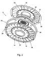
Fig. 1 eine perspektivische Vorderansicht eines Stators mit einer zweiteiligen Schaufel gemäß der vorliegenden Erfindung ist; -
Fig. 2 eine Vorderansicht des Stators inFig. 1 in Explosionsdarstellung ist; -
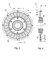
Fig. 3 eine Vorderansicht des Stators inFig. 1 ist; -
Fig. 4 eine seitliche Querschnittsansicht des Stators inFig. 3 entlang der Schnittlinie 4-4 inFig. 3 ist; -
Fig. 5 eine Querschnittsansicht des Stators inFig. 4 von hinten entlang der Schnittlinie 5-5 inFig. 4 ist; - die
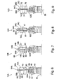
Figuren 6 bis 9 Teilquerschnittsansichten von Statoren mit Schaufeln gemäß der vorliegenden Erfindung sind, die Anordnungen entsprechender Statoren und Schaufeln zeigen; - die
Figuren 10 bis 17 -
Fig. 18A eine perspektivische Ansicht eines Zylinderkoordinatensystems ist, welche die in der vorliegenden Patentanmeldung gebrauchte räumliche Bezeichnungsweise verdeutlicht. -
Fig. 18B eine perspektivische Ansicht eines Objektes in dem Zylinderkoordinatensystem vonFig. 18A ist, die die bei der vorliegenden Erfindung verwendete Bezeichnungsweise verdeutlicht.
-
Fig. 1 a front perspective view of a stator with a two-part blade according to the present invention; -
Fig. 2 a front view of the stator inFig. 1 in exploded view; -
Fig. 3 a front view of the stator inFig. 1 is; -
Fig. 4 a lateral cross-sectional view of the stator inFig. 3 along the section line 4-4 inFig. 3 is; -
Fig. 5 a cross-sectional view of the stator inFig. 4 from behind along the section 5-5 inFig. 4 is; - the
FIGS. 6 to 9 Partial cross-sectional views of stators with blades according to the present invention are showing arrangements of respective stators and blades; - the
FIGS. 10 to 17 Planes on blades according to the present invention are showing various arrangements of the blades; -
Fig. 18A Figure 3 is a perspective view of a cylindrical coordinate system illustrating the spatial notation used in the present application. -
Fig. 18B a perspective view of an object in the cylindrical coordinate system ofFig. 18A which illustrates the mode of description used in the present invention.
Von vornherein sollte klar sein, dass gleiche Bezugsnummern in verschiedenen Zeichnungsansichten identische oder funktionell ähnliche Strukturelemente der Erfindung bezeichnen. Obwohl die vorliegende Erfindung unter Bezug auf die gegenwärtig als bevorzugt angesehenen Aspekte beschrieben wird, sollte klar sein, dass die beanspruchte Erfindung nicht auf die beschriebenen Aspekte beschränkt ist.It should be understood in advance that like reference numerals in different drawing views designate identical or functionally similar structural elements of the invention. Although the present invention will be described with reference to the aspects presently considered to be preferred, it should be understood that the claimed invention is not limited to the aspects described.
Außerdem sollte klar sein, dass die vorliegende Erfindung nicht auf die bestimmten beschriebenen Verfahren, Materialien und Modifikationen beschränkt ist und insofern natürlich variieren kann. Ferner ist klar, dass die hier gebrauchte Terminologie nur zur Beschreibung bestimmte Aspekte dient und nicht als Einschränkung des Geltungsbereichs der vorliegenden Erfindung zu verstehen ist, der nur durch die angehängten Ansprüche beschränkt wird.It should also be understood that the present invention is not limited to the particular methods, materials, and modifications described, and to that extent, of course, may vary. It is further understood that the terminology used herein is for the purpose of describing particular aspects only and is not to be construed as limiting the scope of the present invention, which is limited only by the appended claims.
Wenn nicht anders definiert, haben alle hier verwendeten technischen und wissenschaftlichen Begriffe dieselbe Bedeutung, wie sie dem Fachmann geläufig sind, an den sich diese Erfindung richtet. Obwohl zum Ausführen oder Testen der Erfindung beliebige Verfahren, Vorrichtungen oder Materialien verwendet werden können, die den hier beschriebenen ähnlich oder gleichwertig sind, werden im Folgenden die bevorzugten Verfahren, Vorrichtungen und Materialien beschrieben.Unless otherwise defined, all technical and scientific terms used herein have the same meaning as commonly understood to one of ordinary skill in the art to which this invention belongs. Although any methods, devices, or materials similar or equivalent to those described herein may be used to practice or test the invention, the preferred methods, devices, and materials are described below.
Die Adverbien "axial", "radiale und "Umfangs-" beziehen sich auf eine Ausrichtung parallel zur Achse 281, zum Radius 282 bzw. zum Umfang 284. Die Adverbien "axial", "radial" und "Umfangs-" betreffen auch eine zu entsprechenden Ebenen parallele Ausrichtung.The adverbs "axial," "radial," and "circumferential" refer to an orientation parallel to
-
Fig. 1 ist eine perspektivische Vorderansicht eines Stators mit einer zweiteiligen Schaufel 10 gemäß der vorliegenden Erfindung. -
Fig. 2 ist eine Vorderansicht des Stators inFig. 1 in Explosionsdarstellung. -
Fig. 3 ist eine Vorderansicht des Stators inFig. 1 . -
Fig. 4 ist eine seitliche Querschnittsansicht des Stators inFig. 3 entlang der Schnittlinie 4-4 inFig. 3 . -
Fig. 5 ist eine Querschnittsansicht des Stators inFig. 4 von hinten entlang der Schnittlinie 5-5 inFig. 4 . Die folgende Beschreibung ist in Verbindung mit denFiguren 1 zu sehen.bis 5Im Stator 12sind Schaufeln 10 dargestellt. Gemäß einigen Aspekten beinhaltet jede Schaufel 10Schaufelsegmente 14und 16.Die Segmente 14 und 16 sind getrennt gebildet. Das heißt, dieSegmente 14 und 16 sind Einzelteile. Somitist der Stator 12 mit "zusammengesetzten" Schaufeln gebildet, die wiederum aus zwei getrennten Teilen oder Segmenten gebildet sind. Die getrennten Teile oder Segmente können in der im Folgenden beschriebenen Weise miteinander verbunden, gekoppelt, in Kontakt gebracht, ausgerichtet oder angeordnet werden.Die Segmente 14 und 16 sind jeweils mit einem inneren Umfangsabschnitt 18 und einem äußeren Umfangsabschnitt 20 desStators 12 verbunden. Das heißt, die Segmente sind zwischenden Abschnitten 18 und 20 durchgehend.
-
Fig. 1 FIG. 12 is a front perspective view of a stator with a two-part blade 10 in accordance with the present invention. FIG. -
Fig. 2 is a front view of the stator inFig. 1 in exploded view. -
Fig. 3 is a front view of the stator inFig. 1 , -
Fig. 4 is a side cross-sectional view of the stator inFig. 3 along the section line 4-4 inFig. 3 , -
Fig. 5 is a cross-sectional view of the stator inFig. 4 from behind along the section 5-5 inFig. 4 , The following description is in connection with theFIGS. 1 to 5 to see. In thestator 12blades 10 are shown. In some aspects, eachblade 10 includesblade segments Segments segments stator 12 with formed "composite" blades, which in turn are formed of two separate parts or segments. The separated parts or segments may be interconnected, coupled, contacted, aligned or arranged in the manner described below. Thesegments peripheral portion 18 and an outerperipheral portion 20 of thestator 12. That is, the segments are continuous betweensections
In den Figuren ist jede Schaufel 10 mit entsprechenden Segmenten 14 und 16 dargestellt. Es sollte jedoch klar sein, dass die vorliegende Erfindung nicht auf ein Verhältnis zwischen den Segmenten 14 und 16 von eins zu eins beschränkt ist. Das heißt, die Schaufeln 10 können mit unterschiedlichen Anzahlen von Segmenten 14 und 16 gebildet werden. Zum Beispiel kann eine bestimmte Anzahl von Schaufeln 16 sowohl mit den Segmenten 14 als auch mit den Segmenten 16, eine andere Anzahl von Schaufeln ausschließlich mit Segmenten 14 und noch eine andere Anzahl von Schaufeln ausschließlich mit Segmenten 16 gebildet werden.In the figures, each
Die Segmente 14 und 16 können auf vielfältige Weise angeordnet werden, um die Schaufel 10 zu bilden. Gemäß einigen Aspekten berühren sich die Segmente zum Beispiel entlang den in den
Bekanntlich können Statoren unter dem Gesichtspunkt von Leistungskenndaten betrachtet werden, darunter, aber nicht ausschließlich, das Drehmomentverhältnis, der Wirkungsgrad und die Leistung. Im Allgemeinen werden diese Kenndaten durch die Schaufeln des Stators, zum Beispiel durch die Anordnung der Schaufeln, beeinflusst. Aus diesem Grund können zur Änderung der Leistungskenndaten eines Stators mit den darin befindlichen Schaufeln 10 entsprechende Anordnungen von Schaufeln 10 und Schaufelsegmenten 14 und 16 gewählt werden. Die Anordnung der Schaufeln und Schaufelsegmente kann eine axiale Ausrichtung, eine radiaie Ausrichtung oder eine Ausrichtung über den Umfang hinweg betreffen. Von besonderem Interesse ist die Ausrichtung der Schaufeln in Bezug auf die zu erwartende Richtung des Flüssigkeitsstroms im Stator.As is known, stators may be considered from the point of view of performance characteristics, including, but not limited to, torque ratio, efficiency, and performance. In general, these characteristics are influenced by the blades of the stator, for example by the arrangement of the blades. For this reason, to change the performance characteristics of a stator with the
Gemäß einigen Aspekten beinhaltet der Stator 12 Hälften 36 und 38, zum Beispiel zwei axial voneinander getrennte Hälften, wie sie in der an denselben Anmelder abgetretenen US-Patentanmeldung mit dem Titel "Integral Stator and One-Way Clutch" von George et al., angemeldet am selben Tag wie die vorliegende Erfindung, beschrieben wird. Unter Hälften ist zu verstehen, dass die Struktur des Stators, insbesondere die Struktur, mit welcher die Schaufeln verbunden sind, im Wesentlichen durch Hälften 36 und 38 gebildet ist. Die Hälften 36 und 38 können auch als axiale Hälften oder axiale Abschlüsse bezeichnet werden. Mit anderen Worten, die Hälften 36 und 38 sind entlang einer radialen Ebene bezüglich der Achse 34 miteinander verbunden. Die Hälften sind jeweils aus Einzelteilen gebildet. Das heißt, die Hälften sind getrennt gebildet. Die Schaufelsegmente 14 sind mit der Hälfte 36 verbunden, und die Schaufelsegmente 16 sind mit der Hälfte 38 verbunden. Gemäß einigen Aspekten sind die Segmente als integraler Bestandteil mit der Hälfte 36 und die Schaufelsegmente 16 als integraler Bestandteil mit der Hälfte 38 gebildet. Zum Beispiel sind die Segmente 14 und die Hälfte 36 aus einem Stück Material gebildet.In some aspects, the
Im Allgemeinen sind die Hälften miteinander verbunden und in axialer Richtung fixiert. Das heißt, die Hälften sind auf beliebige Weise miteinander verbunden und verschieben sich in axialer Richtung nicht gegeneinander. Gemäß einigen Aspekten sind die Hälften fest miteinander verbunden. Das heißt, die Hälften verschieben sich weder in axialer noch in Drehrichtung gegeneinander. Gemäß einigen Aspekten sind die Hälften so angeordnet, dass sie sich in Drehrichtung gegeneinander verschieben, wie im Folgenden beschrieben wird. In den
Die
Die Schaufeln 10, die Segmente 14 und 16 sowie die Hälften 26 und 38 sind nicht auf eine bestimmte Anordnung, Form, Größe, Ausrichtung oder Verbindung beschränkt. In den
In den
In den
Zum Verbinden der entsprechenden Hälften in den Bereichen 64 können beliebige in der Technik bekannte Mittel verwendet werden. Zum Beispiel zeigen die
Die
Die
Gemäß einigen Aspekten kann der in den
Gemäß einigen (nicht gezeigten) Aspekten erfolgt die Einstellung automatisch. Das heißt, der Stator 12 beinhaltet ein automatisches Ausrichtungselement oder eine Einstelleinrichtung für mindestens einen Teil einer oder beider Hälften 36 und 38. Zur einfacheren Darstellung wird in der folgenden Erörterung die Einstellung für die Hälften beschrieben, jedoch sollte klar sein, dass diese Einstellung auch nur für einen Teil der entsprechenden Hälfte möglich ist. Die Einstelleinrichtung steuert die Drehung der Hälften (zur Änderung des Versatzes der Segmente 14 und 16 in den Schaufeln 10 über den Umfang hinweg) als Reaktion auf ausgewählte Steuerparameter. Gemäß einigen Aspekten ist die Einrichtung mechanischer Natur, zum Beispiel in Form eines Widerstandselements, das einen "aktiven" Widerstand entgegensetzt, um unter bestimmten Betriebsbedingungen im Stator einen bestimmten Versatz einzustellen. Wenn sich die Betriebsbedingungen im Stator ändern, ändern sich dem Widerstand entgegenwirkende Kräfte im Stator und bewirken eine Drehung der Hälften gegeneinander. Dadurch ändert sich auch der aktuelle Versatz zwischen den Schaufelsegmenten. Als Widerstandselement kommt zum Beispiel eine Feder infrage, wobei sich der Komprimierungsgrad der Feder in Abhängigkeit vom Flüssigkeitsdruck auf die Schaufeln des Stators ändert. Beispielsweise kann eine Erhöhung des Flüssigkeitsdruck zum Zusammendrücken der Feder führen. Als Widerstandselement kann eine beliebige in der Technik bekannte Widerstandseinrichtung verwendet werden.According to some aspects (not shown), the adjustment is made automatically. That is, the
Gemäß einigen Aspekten wird ein elektromechanisches Ausrichtungselement verwendet. Zum Beispiel sind mit den Hälften 36 und 38 elektrische Stellglieder oder elektromechanische Einrichtungen verbunden, die die Hälften als Reaktion auf Steuersignale drehen. Die Steuersignale können durch ein beliebiges in der Technik bekanntes Mittel erzeugt werden, darunter, aber nicht darauf beschränkt, Sensoren zur Messung von Parametern im Stator, zum Beispiel des Flüssigkeitsdrucks oder des Flüssigkeitsstroms, oder Sensoren zur Überwachung der Betriebsparameter einer Antriebseinheit oder einer angetriebenen Einheit für ein Fahrzeug, in welchem sich der Stator befindet.In some aspects, an electromechanical alignment element is used. For example, halves 36 and 38 connect electrical actuators or electromechanical devices that rotate the halves in response to control signals. The control signals may be generated by any means known in the art, including, but not limited to, sensors for measuring parameters in the stator, such as fluid pressure or fluid flow, or sensors for monitoring operational parameters Drive unit or a driven unit for a vehicle in which the stator is located.
Die Schaufeln 10, die Segmente 14 und 16 sowie die Hälften 36 und 38 werden durch Stanzen gebildet.The
Somit ist zu erkennen, dass die Aufgaben der vorliegenden Erfindung wirksam gelöst werden, obwohl sich der Fachmann Modifikationen und Änderungen der Erfindung vorstellen kann, die in Geltungsbereich der beanspruchten Erfindung enthalten sind. Ferner ist klar, dass die vorhergehende Beschreibung nur zur Veranschaulichung der vorliegenden Erfindung dient und nicht als Einschränkung zu verstehen ist. Deshalb sind andere Ausführungsarten der vorliegenden Erfindung möglich, ohne von Geltungsbereich der vorliegenden Erfindung abzuweichen.Thus, it will be appreciated that the objects of the present invention will be effectively attained, although those skilled in the art may conceive of modifications and variations of the invention which are within the scope of the claimed invention. It should also be understood that the foregoing description is intended to be illustrative of the present invention and is not to be construed as limiting. Therefore, other embodiments of the present invention are possible without departing from the scope of the present invention.
Claims (18)
- Blade in a stator in a torque converter, the said blade comprising the following:a first axial blade segment which is formed as an integral part of first inner and outer circumferential portions of the stator;and a second axial blade segment which is formed axially separately from the first blade segment and as an integral part of second inner and outer circumferential portions,the first and second axial blade segment and the first and second inner and outer circumferential portions being stamped, and the first and second inner and outer circumferential portions defining a ring of the stator and being fixedly connected to one another by means of fastening elements.
- Blade according to Claim 1, in which the first and the second blade segment touch one another.
- Blade according to Claim 2, in which the first and the second segment comprise, furthermore, corresponding edges, and the first and the second blade segment touch one another along the corresponding edges.
- Blade according to Claim 3, in which at least one of the corresponding edges is bevelled in a wedge-shaped manner.
- Blade according to Claim 2, in which the first and the second blade segment comprise, furthermore, corresponding faces, and the corresponding faces at least partially overlap one another.
- Blade according to Claim 1, in which the first and the second blade segment are offset with respect to one another over the circumference.
- Blade according to Claim 1, the stator comprising, furthermore, performance characteristic data, the first and the second blade segment assuming corresponding arrangements, and the corresponding arrangements being selected such that they vary the performance characteristic data.
- Blade according to Claim 7, in which the performance characteristic data selected are, inter alia, the torque ratio, the efficiency and the performance.
- Blade according to Claim 7, in which the corresponding arrangements selected are, inter alia, axial orientation, radial orientation and orientation over the circumference.
- Blade according to Claim 1, in which the first and the second blade segment are oriented over the circumference, and the stator comprises, furthermore, an orientation element which is arranged functionally such that it controls the orientation over the circumference.
- Blade according to Claim 10, the torque converter comprising, furthermore, a fluid, and the orientation element being arranged such that it controls the orientation as a reaction to the pressure of the fluid upon the blade.
- Blade according to Claim 1, the stator comprising, furthermore, a first axial half and a second axial half, and the first and the second axial half being formed separately and being connected fixedly to one another, the first blade segment being connected to the first axial half and the second blade segment to the second axial half.
- Blade according to Claim 12, in which the fixed connection selected comprises, inter alia, rivets, folded tongues, weld seams, adhesives and beads.
- Blade according to Claim 12, in which the first blade segment is formed as an integral part of the first axial half and the second blade segment is formed as an integral part of the second axial half.
- Blade according to Claim 12, the stator comprising, furthermore, a clutch, and the first and the second axial half being arranged such that they form respectively a first and a second closing piece of the clutch.
- Blade according to Claim 1, in which the first blade segment is at least partially folded.
- Blade according to Claim 1, in which the second blade segment is at least partially folded.
- Blade according to Claim 1, which, furthermore, comprises the following: a multiplicity of blades; and the first and the second blade segment comprising, furthermore, corresponding multiplicities of the first and of the second blade segment.
Applications Claiming Priority (2)
| Application Number | Priority Date | Filing Date | Title |
|---|---|---|---|
| US78573906P | 2006-03-24 | 2006-03-24 | |
| PCT/DE2007/000354 WO2007110019A1 (en) | 2006-03-24 | 2007-02-23 | Two-piece stator blade |
Publications (2)
| Publication Number | Publication Date |
|---|---|
| EP2002151A1 EP2002151A1 (en) | 2008-12-17 |
| EP2002151B1 true EP2002151B1 (en) | 2011-05-11 |
Family
ID=38042662
Family Applications (1)
| Application Number | Title | Priority Date | Filing Date |
|---|---|---|---|
| EP07711207A Not-in-force EP2002151B1 (en) | 2006-03-24 | 2007-02-23 | Two-piece stator blade |
Country Status (7)
| Country | Link |
|---|---|
| US (1) | US7850420B2 (en) |
| EP (1) | EP2002151B1 (en) |
| JP (1) | JP5286464B2 (en) |
| CN (1) | CN101410654B (en) |
| AT (1) | ATE509217T1 (en) |
| DE (1) | DE112007000496A5 (en) |
| WO (1) | WO2007110019A1 (en) |
Families Citing this family (25)
| Publication number | Priority date | Publication date | Assignee | Title |
|---|---|---|---|---|
| DE102007025407A1 (en) | 2006-06-13 | 2007-12-20 | Luk Lamellen Und Kupplungsbau Beteiligungs Kg | Radial one-way clutch for a stator in a torque converter has an engagement element that is urged to engage the engagement and annular elements for connecting the two annular elements |
| DE102007055146A1 (en) * | 2006-12-21 | 2008-06-26 | Luk Lamellen Und Kupplungsbau Beteiligungs Kg | Free wheel for power transmission in motor vehicle, comprises bearing race arranged around axis of free wheel, and wedge plate with multiple finger elements, which protrude from bearing race |
| DE102008020673B4 (en) * | 2007-05-09 | 2018-10-31 | Schaeffler Technologies AG & Co. KG | Graded stator blade |
| DE102008020678A1 (en) * | 2007-05-09 | 2008-11-13 | Luk Lamellen Und Kupplungsbau Beteiligungs Kg | Three-phase torque converter with sealed piston and forced cooling flow |
| DE102008020681B4 (en) | 2007-05-09 | 2019-08-22 | Schaeffler Technologies AG & Co. KG | Three-piece vane |
| DE102008032460A1 (en) * | 2007-07-31 | 2009-02-05 | Luk Lamellen Und Kupplungsbau Beteiligungs Kg | Torque converter with stator with molded side plate |
| DE102008051107A1 (en) * | 2007-10-31 | 2009-05-07 | Luk Lamellen Und Kupplungsbau Beteiligungs Kg | Connector for a stamped stator and a freewheel |
| DE102008058084A1 (en) | 2007-12-13 | 2009-06-25 | Luk Lamellen Und Kupplungsbau Beteiligungs Kg | Paddle wheel, in particular stator for a hydrodynamic speed / torque converter and method for producing a paddle wheel |
| DE102009012075A1 (en) * | 2008-03-14 | 2009-09-17 | Luk Lamellen Und Kupplungsbau Beteiligungs Kg | Punched nozzle assemblies and methods of mounting stamped nozzle assemblies |
| DE102010010609A1 (en) * | 2009-03-25 | 2010-10-07 | Luk Lamellen Und Kupplungsbau Beteiligungs Kg | Shielded punched stator blade |
| DE102011011471A1 (en) | 2010-03-11 | 2011-09-15 | Schaeffler Technologies Gmbh & Co. Kg | Impeller for use as stator in hydrodynamic component, has blade shape part provided with connecting portions that are molded to form respective connections into inner and outer carrier rings, which are arranged coaxial to each other |
| US20110274533A1 (en) * | 2010-05-07 | 2011-11-10 | Flodesign Wind Turbine Corp. | Fluid turbine with moveable fluid control member |
| US8899032B2 (en) | 2010-09-27 | 2014-12-02 | Schaeffler Technologies Gmbh & Co. Kg | Stator centering plate |
| BR112013032708A2 (en) * | 2011-06-24 | 2017-01-24 | Honda Motor Co Ltd | torque converter stator structure |
| US9046140B2 (en) * | 2012-10-18 | 2015-06-02 | Schaeffler Technologies AG & Co. KG | Conical wedge one-way clutch with split outer race |
| WO2015017195A1 (en) * | 2013-07-30 | 2015-02-05 | Schaeffler Technologies Gmbh & Co. Kg | Torque converter with stamped stator |
| US10094223B2 (en) | 2014-03-13 | 2018-10-09 | Pratt & Whitney Canada Corp. | Integrated strut and IGV configuration |
| JP6537104B2 (en) * | 2014-07-18 | 2019-07-03 | 株式会社エクセディ | Split molding integrated stator |
| US10072746B2 (en) * | 2015-05-05 | 2018-09-11 | Valeo Embrayages | Stator assembly of hydrokinetic torque converter, and method for making the same |
| JP2018189198A (en) * | 2017-05-10 | 2018-11-29 | 株式会社エクセディ | Stator |
| US10830349B2 (en) * | 2018-08-21 | 2020-11-10 | Ford Global Technologies, Llc | Variable pitch stator structure with all blades free to rotate and torque converter with variable pitch stator |
| US10895310B2 (en) * | 2018-08-23 | 2021-01-19 | Schaeffler Technologies AG & Co. KG | Side plate to stator attachment for torque converter |
| CN112576724B (en) * | 2021-01-08 | 2022-03-18 | 吉林大学 | An energy-capacity adjustable torque converter with a bionic slit |
| CN112943700B (en) * | 2021-02-25 | 2022-09-27 | 上海汽车集团股份有限公司 | An engine and its centrifugal compressor and vane diffuser |
| US12215766B1 (en) * | 2024-02-22 | 2025-02-04 | Schaeffler Technologies AG & Co. KG | Modular torque converter stator with cammed blades |
Family Cites Families (22)
| Publication number | Priority date | Publication date | Assignee | Title |
|---|---|---|---|---|
| US2588668A (en) * | 1949-02-23 | 1952-03-11 | Chrysler Corp | Fluid coupling mounting |
| US2755628A (en) * | 1951-05-22 | 1956-07-24 | Borg Warner | Hydraulic torque converter |
| DE1193758B (en) * | 1957-11-23 | 1965-05-26 | Eta Corp G M B H | Multi-stage, hydrodynamic torque converter with triangular cross-section based on the Foettinger principle |
| US3014430A (en) * | 1958-05-19 | 1961-12-26 | Schneider Brothers Company | Hydraulic torque converter |
| US3244400A (en) * | 1964-10-30 | 1966-04-05 | Saunders Walter Selden | Extended range cascade for torque converters and turbo-machinery |
| US3385060A (en) * | 1966-05-02 | 1968-05-28 | Ford Motor Co | Hydrokinetic torque converter mechanism with multiple section reactor blades |
| US3354643A (en) * | 1966-05-18 | 1967-11-28 | Ford Motor Co | Hydrokinetic torque converter mechanism with variable geometry stator blading |
| US3572034A (en) * | 1969-11-21 | 1971-03-23 | Ford Motor Co | Fabricated two-piece stator assembly for hydrokinetic torque converters |
| DE2905738A1 (en) * | 1979-02-15 | 1980-08-28 | Daimler Benz Ag | STEERING WHEEL OF A HYDRODYNAMIC TORQUE CONVERTER |
| JPS6164558U (en) * | 1984-10-02 | 1986-05-01 | ||
| DE3702548A1 (en) * | 1987-01-29 | 1988-08-11 | Ford Werke Ag | HYDRODYNAMIC TORQUE CONVERTER, ESPECIALLY FOR MOTOR VEHICLES |
| DE3931427A1 (en) * | 1988-10-11 | 1990-04-12 | Luk Lamellen & Kupplungsbau | Fluid coupling or torque converter with welded segments - mfd. with integral blades and bonded together in blade contact region |
| US5307629A (en) * | 1992-09-21 | 1994-05-03 | General Motors Corporation | Variable pitch stator with passive control |
| JP3582134B2 (en) * | 1995-03-17 | 2004-10-27 | マツダ株式会社 | Method and apparatus for designing blade shape of torque converter |
| JPH0942413A (en) * | 1995-07-31 | 1997-02-14 | Aisin Seiki Co Ltd | Blade member and forming method thereof |
| JP3028499B2 (en) * | 1995-08-02 | 2000-04-04 | 勝彦 松波 | Adjustment method of torque converter |
| JP3539649B2 (en) * | 1995-10-01 | 2004-07-07 | 株式会社豊田中央研究所 | Impeller for torque converter |
| KR100496764B1 (en) * | 2002-08-30 | 2005-06-23 | 한국파워트레인 주식회사 | blade of stator mounted in a torque convertor |
| JP2006038054A (en) * | 2004-07-26 | 2006-02-09 | Yutaka Giken Co Ltd | Impeller for fluid transmission device |
| US7770707B2 (en) | 2005-08-24 | 2010-08-10 | Luk Lamellen Und Kupplungsbau Beteiligungs Kg | Axially engaging and disengaging one-way clutch and a stator having an axially engaging and disengaging one-way clutch |
| EP1966518A2 (en) | 2005-12-19 | 2008-09-10 | LuK Lamellen und Kupplungsbau Beteiligungs KG | Lateral stator plate for a torque converter |
| US7854588B2 (en) | 2005-12-20 | 2010-12-21 | Schaeffler Technologies Gmbh & Co. Kg | Stamped torque converter stator blades and a torque converter stator with stamped blades |
-
2007
- 2007-02-23 DE DE112007000496T patent/DE112007000496A5/en not_active Withdrawn
- 2007-02-23 AT AT07711207T patent/ATE509217T1/en active
- 2007-02-23 EP EP07711207A patent/EP2002151B1/en not_active Not-in-force
- 2007-02-23 CN CN2007800106057A patent/CN101410654B/en not_active Expired - Fee Related
- 2007-02-23 WO PCT/DE2007/000354 patent/WO2007110019A1/en not_active Ceased
- 2007-02-23 JP JP2009501831A patent/JP5286464B2/en not_active Expired - Fee Related
- 2007-03-23 US US11/728,066 patent/US7850420B2/en not_active Expired - Fee Related
Also Published As
| Publication number | Publication date |
|---|---|
| US7850420B2 (en) | 2010-12-14 |
| WO2007110019A1 (en) | 2007-10-04 |
| US20070224042A1 (en) | 2007-09-27 |
| JP2009531605A (en) | 2009-09-03 |
| EP2002151A1 (en) | 2008-12-17 |
| DE112007000496A5 (en) | 2008-11-27 |
| ATE509217T1 (en) | 2011-05-15 |
| CN101410654B (en) | 2012-03-21 |
| CN101410654A (en) | 2009-04-15 |
| JP5286464B2 (en) | 2013-09-11 |
Similar Documents
| Publication | Publication Date | Title |
|---|---|---|
| EP2002151B1 (en) | Two-piece stator blade | |
| EP2076682B1 (en) | Coupling device | |
| EP2054263B1 (en) | Transmission device for a vehicle seat | |
| DE112017000866T5 (en) | Centrifugal impeller for HVAC applications | |
| DE2843289C2 (en) | ||
| DE10058935B4 (en) | Device for fastening a fan screw to a drive shaft | |
| DE102007058417B4 (en) | TURBINE AND PUMP WHEELS FOR TORQUE CONVERTERS | |
| DE3044415A1 (en) | ELASTIC COUPLING FOR TRANSMITTING A ROTATING MOTION | |
| EP2229541B1 (en) | Torque transfer device of a motor vehicle | |
| DE102007058019A1 (en) | Freewheel for stator in torque converter for power transmission between rotary drive unit and rotary driven unit, has spacer element with segment, which is toothed on circumference with guide rail | |
| DE10311618B4 (en) | Air blower with a fan that can not be brought into contact with the motor housing | |
| DE102015213725A1 (en) | Planet carrier composed of segments | |
| WO2021219497A1 (en) | Shaft, forming tool, method of production and rotor for an electric machine | |
| DE102007042835A1 (en) | Rotation element i.e. belt pulley, and hub connection, has rotation element provided on connection socket, where rotation element has opening corresponding to polygonal shape of connection socket | |
| DE102017204553A1 (en) | VALVE DEVICE, VALVE HOUSING, GEARING DEVICE AND METHOD FOR MANUFACTURING THE VALVE DEVICE | |
| DE102024200986A1 (en) | STEERING ARRANGEMENT FOR A VEHICLE | |
| EP3375272B1 (en) | Packer roller for soil cultivation | |
| EP1801459A1 (en) | Blade and blade assembly for a torque converter reactor, reactor with blades for a torque converter, and method for producing the same | |
| EP1657404B1 (en) | Turbomachine rotor, in particular gas turbine rotor | |
| EP1431604B1 (en) | Universal joint with retainer element. | |
| EP3523547A1 (en) | Tripod roller for a constant velocity universal joint with securing region, constant velocity universal joint with the tripod roller, and method for assembling the tripod roller | |
| DE102009018297A1 (en) | Piston system, particularly for a hydraulic axial piston machine for sealing piston guided in cylinder, has piston with piston groove, in which piston ring is arranged, where another piton ring is arranged coaxially to former piston ring | |
| DE102016216704A1 (en) | shaft coupling | |
| DE19544997C1 (en) | Rotation sensor for e.g. vehicular throttle flap or accelerator pedal - features combination of inner and outer sleeved elements on rotor and shaft secured against relative movement in radial and axial directions | |
| DE19808035A1 (en) | Elastic shaft coupling with drive and driven side coupling parts |
Legal Events
| Date | Code | Title | Description |
|---|---|---|---|
| PUAI | Public reference made under article 153(3) epc to a published international application that has entered the european phase |
Free format text: ORIGINAL CODE: 0009012 |
|
| 17P | Request for examination filed |
Effective date: 20081024 |
|
| AK | Designated contracting states |
Kind code of ref document: A1 Designated state(s): AT BE BG CH CY CZ DE DK EE ES FI FR GB GR HU IE IS IT LI LT LU LV MC NL PL PT RO SE SI SK TR |
|
| 17Q | First examination report despatched |
Effective date: 20091007 |
|
| RAP1 | Party data changed (applicant data changed or rights of an application transferred) |
Owner name: SCHAEFFLER TECHNOLOGIES GMBH & CO. KG |
|
| RIC1 | Information provided on ipc code assigned before grant |
Ipc: F16H 41/28 20060101AFI20101119BHEP Ipc: F16H 41/26 20060101ALI20101119BHEP |
|
| GRAP | Despatch of communication of intention to grant a patent |
Free format text: ORIGINAL CODE: EPIDOSNIGR1 |
|
| DAX | Request for extension of the european patent (deleted) | ||
| GRAS | Grant fee paid |
Free format text: ORIGINAL CODE: EPIDOSNIGR3 |
|
| GRAA | (expected) grant |
Free format text: ORIGINAL CODE: 0009210 |
|
| AK | Designated contracting states |
Kind code of ref document: B1 Designated state(s): AT BE BG CH CY CZ DE DK EE ES FI FR GB GR HU IE IS IT LI LT LU LV MC NL PL PT RO SE SI SK TR |
|
| REG | Reference to a national code |
Ref country code: GB Ref legal event code: FG4D Free format text: NOT ENGLISH |
|
| REG | Reference to a national code |
Ref country code: CH Ref legal event code: EP |
|
| REG | Reference to a national code |
Ref country code: IE Ref legal event code: FG4D |
|
| REG | Reference to a national code |
Ref country code: DE Ref legal event code: R096 Ref document number: 502007007174 Country of ref document: DE Effective date: 20110622 |
|
| REG | Reference to a national code |
Ref country code: NL Ref legal event code: VDEP Effective date: 20110511 |
|
| PG25 | Lapsed in a contracting state [announced via postgrant information from national office to epo] |
Ref country code: LT Free format text: LAPSE BECAUSE OF FAILURE TO SUBMIT A TRANSLATION OF THE DESCRIPTION OR TO PAY THE FEE WITHIN THE PRESCRIBED TIME-LIMIT Effective date: 20110511 Ref country code: SE Free format text: LAPSE BECAUSE OF FAILURE TO SUBMIT A TRANSLATION OF THE DESCRIPTION OR TO PAY THE FEE WITHIN THE PRESCRIBED TIME-LIMIT Effective date: 20110511 Ref country code: PT Free format text: LAPSE BECAUSE OF FAILURE TO SUBMIT A TRANSLATION OF THE DESCRIPTION OR TO PAY THE FEE WITHIN THE PRESCRIBED TIME-LIMIT Effective date: 20110912 |
|
| PG25 | Lapsed in a contracting state [announced via postgrant information from national office to epo] |
Ref country code: SI Free format text: LAPSE BECAUSE OF FAILURE TO SUBMIT A TRANSLATION OF THE DESCRIPTION OR TO PAY THE FEE WITHIN THE PRESCRIBED TIME-LIMIT Effective date: 20110511 Ref country code: FI Free format text: LAPSE BECAUSE OF FAILURE TO SUBMIT A TRANSLATION OF THE DESCRIPTION OR TO PAY THE FEE WITHIN THE PRESCRIBED TIME-LIMIT Effective date: 20110511 Ref country code: ES Free format text: LAPSE BECAUSE OF FAILURE TO SUBMIT A TRANSLATION OF THE DESCRIPTION OR TO PAY THE FEE WITHIN THE PRESCRIBED TIME-LIMIT Effective date: 20110822 Ref country code: IS Free format text: LAPSE BECAUSE OF FAILURE TO SUBMIT A TRANSLATION OF THE DESCRIPTION OR TO PAY THE FEE WITHIN THE PRESCRIBED TIME-LIMIT Effective date: 20110911 Ref country code: GR Free format text: LAPSE BECAUSE OF FAILURE TO SUBMIT A TRANSLATION OF THE DESCRIPTION OR TO PAY THE FEE WITHIN THE PRESCRIBED TIME-LIMIT Effective date: 20110812 Ref country code: LV Free format text: LAPSE BECAUSE OF FAILURE TO SUBMIT A TRANSLATION OF THE DESCRIPTION OR TO PAY THE FEE WITHIN THE PRESCRIBED TIME-LIMIT Effective date: 20110511 Ref country code: CY Free format text: LAPSE BECAUSE OF FAILURE TO SUBMIT A TRANSLATION OF THE DESCRIPTION OR TO PAY THE FEE WITHIN THE PRESCRIBED TIME-LIMIT Effective date: 20110511 |
|
| REG | Reference to a national code |
Ref country code: IE Ref legal event code: FD4D |
|
| PG25 | Lapsed in a contracting state [announced via postgrant information from national office to epo] |
Ref country code: NL Free format text: LAPSE BECAUSE OF FAILURE TO SUBMIT A TRANSLATION OF THE DESCRIPTION OR TO PAY THE FEE WITHIN THE PRESCRIBED TIME-LIMIT Effective date: 20110511 |
|
| PG25 | Lapsed in a contracting state [announced via postgrant information from national office to epo] |
Ref country code: IE Free format text: LAPSE BECAUSE OF FAILURE TO SUBMIT A TRANSLATION OF THE DESCRIPTION OR TO PAY THE FEE WITHIN THE PRESCRIBED TIME-LIMIT Effective date: 20110511 Ref country code: EE Free format text: LAPSE BECAUSE OF FAILURE TO SUBMIT A TRANSLATION OF THE DESCRIPTION OR TO PAY THE FEE WITHIN THE PRESCRIBED TIME-LIMIT Effective date: 20110511 Ref country code: CZ Free format text: LAPSE BECAUSE OF FAILURE TO SUBMIT A TRANSLATION OF THE DESCRIPTION OR TO PAY THE FEE WITHIN THE PRESCRIBED TIME-LIMIT Effective date: 20110511 |
|
| PG25 | Lapsed in a contracting state [announced via postgrant information from national office to epo] |
Ref country code: DK Free format text: LAPSE BECAUSE OF FAILURE TO SUBMIT A TRANSLATION OF THE DESCRIPTION OR TO PAY THE FEE WITHIN THE PRESCRIBED TIME-LIMIT Effective date: 20110511 Ref country code: RO Free format text: LAPSE BECAUSE OF FAILURE TO SUBMIT A TRANSLATION OF THE DESCRIPTION OR TO PAY THE FEE WITHIN THE PRESCRIBED TIME-LIMIT Effective date: 20110511 Ref country code: PL Free format text: LAPSE BECAUSE OF FAILURE TO SUBMIT A TRANSLATION OF THE DESCRIPTION OR TO PAY THE FEE WITHIN THE PRESCRIBED TIME-LIMIT Effective date: 20110511 Ref country code: SK Free format text: LAPSE BECAUSE OF FAILURE TO SUBMIT A TRANSLATION OF THE DESCRIPTION OR TO PAY THE FEE WITHIN THE PRESCRIBED TIME-LIMIT Effective date: 20110511 |
|
| RAP2 | Party data changed (patent owner data changed or rights of a patent transferred) |
Owner name: SCHAEFFLER TECHNOLOGIES AG & CO. KG |
|
| REG | Reference to a national code |
Ref country code: CH Ref legal event code: PFA Owner name: SCHAEFFLER TECHNOLOGIES AG & CO. KG Free format text: SCHAEFFLER TECHNOLOGIES GMBH & CO. KG#INDUSTRIESTRASSE 1-3#91074 HERZOGENAURACH (DE) -TRANSFER TO- SCHAEFFLER TECHNOLOGIES AG & CO. KG#INDUSTRIESTRASSE 1-3#91074 HERZOGENAURACH (DE) |
|
| PLBE | No opposition filed within time limit |
Free format text: ORIGINAL CODE: 0009261 |
|
| STAA | Information on the status of an ep patent application or granted ep patent |
Free format text: STATUS: NO OPPOSITION FILED WITHIN TIME LIMIT |
|
| 26N | No opposition filed |
Effective date: 20120214 |
|
| PG25 | Lapsed in a contracting state [announced via postgrant information from national office to epo] |
Ref country code: IT Free format text: LAPSE BECAUSE OF FAILURE TO SUBMIT A TRANSLATION OF THE DESCRIPTION OR TO PAY THE FEE WITHIN THE PRESCRIBED TIME-LIMIT Effective date: 20110511 |
|
| REG | Reference to a national code |
Ref country code: DE Ref legal event code: R097 Ref document number: 502007007174 Country of ref document: DE Effective date: 20120214 |
|
| BERE | Be: lapsed |
Owner name: SCHAEFFLER TECHNOLOGIES G.M.B.H. & CO. KG Effective date: 20120228 |
|
| PG25 | Lapsed in a contracting state [announced via postgrant information from national office to epo] |
Ref country code: MC Free format text: LAPSE BECAUSE OF NON-PAYMENT OF DUE FEES Effective date: 20120229 |
|
| REG | Reference to a national code |
Ref country code: CH Ref legal event code: PL |
|
| REG | Reference to a national code |
Ref country code: DE Ref legal event code: R081 Ref document number: 502007007174 Country of ref document: DE Owner name: SCHAEFFLER TECHNOLOGIES AG & CO. KG, DE Free format text: FORMER OWNER: SCHAEFFLER TECHNOLOGIES GMBH & CO. KG, 91074 HERZOGENAURACH, DE Effective date: 20120828 Ref country code: DE Ref legal event code: R081 Ref document number: 502007007174 Country of ref document: DE Owner name: SCHAEFFLER TECHNOLOGIES GMBH & CO. KG, DE Free format text: FORMER OWNER: SCHAEFFLER TECHNOLOGIES GMBH & CO. KG, 91074 HERZOGENAURACH, DE Effective date: 20120828 |
|
| GBPC | Gb: european patent ceased through non-payment of renewal fee |
Effective date: 20120223 |
|
| PG25 | Lapsed in a contracting state [announced via postgrant information from national office to epo] |
Ref country code: LI Free format text: LAPSE BECAUSE OF NON-PAYMENT OF DUE FEES Effective date: 20120229 Ref country code: CH Free format text: LAPSE BECAUSE OF NON-PAYMENT OF DUE FEES Effective date: 20120229 |
|
| PG25 | Lapsed in a contracting state [announced via postgrant information from national office to epo] |
Ref country code: BE Free format text: LAPSE BECAUSE OF NON-PAYMENT OF DUE FEES Effective date: 20120228 |
|
| PG25 | Lapsed in a contracting state [announced via postgrant information from national office to epo] |
Ref country code: GB Free format text: LAPSE BECAUSE OF NON-PAYMENT OF DUE FEES Effective date: 20120223 |
|
| REG | Reference to a national code |
Ref country code: AT Ref legal event code: MM01 Ref document number: 509217 Country of ref document: AT Kind code of ref document: T Effective date: 20120223 |
|
| PG25 | Lapsed in a contracting state [announced via postgrant information from national office to epo] |
Ref country code: AT Free format text: LAPSE BECAUSE OF NON-PAYMENT OF DUE FEES Effective date: 20120223 Ref country code: BG Free format text: LAPSE BECAUSE OF FAILURE TO SUBMIT A TRANSLATION OF THE DESCRIPTION OR TO PAY THE FEE WITHIN THE PRESCRIBED TIME-LIMIT Effective date: 20110811 |
|
| REG | Reference to a national code |
Ref country code: DE Ref legal event code: R081 Ref document number: 502007007174 Country of ref document: DE Owner name: SCHAEFFLER TECHNOLOGIES GMBH & CO. KG, DE Free format text: FORMER OWNER: SCHAEFFLER TECHNOLOGIES AG & CO. KG, 91074 HERZOGENAURACH, DE Effective date: 20140212 Ref country code: DE Ref legal event code: R081 Ref document number: 502007007174 Country of ref document: DE Owner name: SCHAEFFLER TECHNOLOGIES AG & CO. KG, DE Free format text: FORMER OWNER: SCHAEFFLER TECHNOLOGIES AG & CO. KG, 91074 HERZOGENAURACH, DE Effective date: 20140212 |
|
| PG25 | Lapsed in a contracting state [announced via postgrant information from national office to epo] |
Ref country code: TR Free format text: LAPSE BECAUSE OF FAILURE TO SUBMIT A TRANSLATION OF THE DESCRIPTION OR TO PAY THE FEE WITHIN THE PRESCRIBED TIME-LIMIT Effective date: 20110511 |
|
| PG25 | Lapsed in a contracting state [announced via postgrant information from national office to epo] |
Ref country code: LU Free format text: LAPSE BECAUSE OF NON-PAYMENT OF DUE FEES Effective date: 20120223 |
|
| PG25 | Lapsed in a contracting state [announced via postgrant information from national office to epo] |
Ref country code: HU Free format text: LAPSE BECAUSE OF FAILURE TO SUBMIT A TRANSLATION OF THE DESCRIPTION OR TO PAY THE FEE WITHIN THE PRESCRIBED TIME-LIMIT Effective date: 20070223 |
|
| REG | Reference to a national code |
Ref country code: DE Ref legal event code: R081 Ref document number: 502007007174 Country of ref document: DE Owner name: SCHAEFFLER TECHNOLOGIES AG & CO. KG, DE Free format text: FORMER OWNER: SCHAEFFLER TECHNOLOGIES GMBH & CO. KG, 91074 HERZOGENAURACH, DE Effective date: 20150127 |
|
| REG | Reference to a national code |
Ref country code: FR Ref legal event code: PLFP Year of fee payment: 10 |
|
| REG | Reference to a national code |
Ref country code: FR Ref legal event code: PLFP Year of fee payment: 11 |
|
| REG | Reference to a national code |
Ref country code: FR Ref legal event code: PLFP Year of fee payment: 12 |
|
| PGFP | Annual fee paid to national office [announced via postgrant information from national office to epo] |
Ref country code: DE Payment date: 20200429 Year of fee payment: 14 |
|
| REG | Reference to a national code |
Ref country code: DE Ref legal event code: R119 Ref document number: 502007007174 Country of ref document: DE |
|
| PG25 | Lapsed in a contracting state [announced via postgrant information from national office to epo] |
Ref country code: DE Free format text: LAPSE BECAUSE OF NON-PAYMENT OF DUE FEES Effective date: 20210901 |
|
| PGFP | Annual fee paid to national office [announced via postgrant information from national office to epo] |
Ref country code: FR Payment date: 20220217 Year of fee payment: 16 |
|
| P01 | Opt-out of the competence of the unified patent court (upc) registered |
Effective date: 20230522 |
|
| PG25 | Lapsed in a contracting state [announced via postgrant information from national office to epo] |
Ref country code: FR Free format text: LAPSE BECAUSE OF NON-PAYMENT OF DUE FEES Effective date: 20230228 |