EP2002137B1 - Riemenscheibenanordnung für einen start-stopp-riementrieb - Google Patents
Riemenscheibenanordnung für einen start-stopp-riementrieb Download PDFInfo
- Publication number
- EP2002137B1 EP2002137B1 EP06728500A EP06728500A EP2002137B1 EP 2002137 B1 EP2002137 B1 EP 2002137B1 EP 06728500 A EP06728500 A EP 06728500A EP 06728500 A EP06728500 A EP 06728500A EP 2002137 B1 EP2002137 B1 EP 2002137B1
- Authority
- EP
- European Patent Office
- Prior art keywords
- pulley
- hub
- end portion
- assembly according
- pulley assembly
- Prior art date
- Legal status (The legal status is an assumption and is not a legal conclusion. Google has not performed a legal analysis and makes no representation as to the accuracy of the status listed.)
- Expired - Lifetime
Links
Images


Classifications
-
- F—MECHANICAL ENGINEERING; LIGHTING; HEATING; WEAPONS; BLASTING
- F16—ENGINEERING ELEMENTS AND UNITS; GENERAL MEASURES FOR PRODUCING AND MAINTAINING EFFECTIVE FUNCTIONING OF MACHINES OR INSTALLATIONS; THERMAL INSULATION IN GENERAL
- F16D—COUPLINGS FOR TRANSMITTING ROTATION; CLUTCHES; BRAKES
- F16D27/00—Magnetically- or electrically- actuated clutches; Control or electric circuits therefor
- F16D27/10—Magnetically- or electrically- actuated clutches; Control or electric circuits therefor with an electromagnet not rotating with a clutching member, i.e. without collecting rings
- F16D27/105—Magnetically- or electrically- actuated clutches; Control or electric circuits therefor with an electromagnet not rotating with a clutching member, i.e. without collecting rings with a helical band or equivalent member co-operating with a cylindrical coupling surface
Definitions
- the present invention relates to a pulley assembly for a start-stop belt drive preferably designed to be connected to a crankshaft of an internal-combustion engine of a motor vehicle.
- Pulley assemblies connected to the crankshaft are generally provided with a damping device and enable simultaneously driving of a belt drive for accessories and damping of the torsional vibrations of the crankshaft.
- internal-combustion engines adopt a control system referred to as start-stop, whereby an electronic control unit turns off the engine when the vehicle is stationary and re-starts the engine when the accelerator pedal is pressed.
- the crankshaft drives the accessories belt drive
- the accessories belt drive is driven by a further driving machine, for example a reversible electric machine connected to the belt drive and functioning either as alternator or as electric motor in response to a control signal of the electronic control unit.
- Pulley assemblies are known provided with a hub, designed to be connected to a crankshaft of an internal-combustion engine, a seismic mass connected to the hub by an element made of elastomeric material so as to define a device for damping the torsional vibrations, and a pulley, rotatably mounted on the hub via a bearing.
- Known pulley assemblies further comprise an armature connected in an angularly fixed and axially mobile way to the hub and actuated via an electromagnet controlled by the electronic control unit.
- the armature In use, the armature is pressed axially against a wall of the pulley via an elastic element and, consequently, provides a friction connection that is angularly fixed between the hub and the pulley.
- the electronic control unit When the internal-combustion engine is turned off, the electronic control unit energises the electromagnet, and the mobile armature recedes against the action of the spring. Consequently, the pulley is de-coupled from the hub, and the belt drive can be actuated by the electric machine whilst the crankshaft remains angularly fixed.
- JP 58 008 833 discloses electromagnetically actuated band clutch to connect a hub to a pulley.
- the aim of the present invention is to provide a pulley assembly for a start-stop belt drive that will be free from the drawbacks referred to above.
- the aim of the present invention is achieved via a pulley assembly for a start-stop belt drive according to Claim 1.
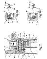
- a pulley assembly comprising a hub 2, which has an axis A and is designed to be connected to a crankshaft of an internal-combustion engine, a pulley 3, connected to the hub 2 via a bearing 4, and a seismic ring 5, connected to the hub 2 via a band 6 made of elastomeric material so as to define a dynamic damper of torsional vibrations.
- the hub 2 is made of a single body of metal plate and has, at respectively increasing concentric diameters, a flange 7, defining holes 8 for connection to the crankshaft, a supporting portion 9, having an L-shaped longitudinal section coming axially out from the flange 7 and defining a seat 10 for the bearing 4, and a C-shaped portion 11, coming axially out from the supporting portion 9.
- the bearing 4 is axially closed in the seat 10 via an annular plate 7a connected to the flange 7.
- the C-shaped portion 11 defines a cavity 12 having an axial opening 13 facing the seat 10 and has a cylindrical wall 14, coming axially out from the supporting portion 9, a side wall 15, transverse to the axis A for closing the cavity 12 on the opposite side of the opening 13, and a cylindrical wall 16, radially external to the cylindrical wall 14 and axially extending up to the flange 7.
- the cylindrical wall 16 supports the band 6 on a face 17 thereof that is radially external with respect to the cavity 12 and has the same axial dimensions as the band 6 and the seismic ring 5.
- the pulley 3 is ringshaped with a substantially C-shaped cross section for housing the dynamic damper at least partially.
- the pulley 3 comprises a tubular wall 18, mounted on the outer ring of the bearing 4, a side wall 19, which is transverse to the axis A and faces axially the opening 13, and a crown wheel 20, which surrounds at least one axial portion of the seismic ring 5 and defines a plurality of grooves 20a designed to co-operate with a belt of a drive (not illustrated).
- the pulley assembly 1 further comprises a band clutch 21, which co-operates between the hub 2 and the pulley 3 within the slot 12 and is governed by an electromagnet 22 fixedly connected to a wall of the internal-combustion engine facing in use the pulley assembly 1.
- the band clutch 21 comprises a coil element 23, wound on both the cylindrical wall 14 and the tubular wall 18, an electromagnetic armature 24, which co-operates with the coil element 23 and is axially mobile under the action of the electromagnet 22, and a helical spring 25, which surrounds the coil element 23 and is set so as to exert an axial load on the armature 24.
- the armature 24 has a tubular portion 26 housed in the cavity 12 and a flange 28 coming out radially from the cylindrical wall 27 and axially set between the seismic ring 5 and the side wall 19.
- the tubular portion 26 comprises an end wall 27, which is axially opposite to the flange 28 and is set between the coil element 23 and the side wall 15.
- the end wall 27 co-operates directly with the helical spring 25 and is pushed by the latter against the side wall 15.
- the coil element 23 comprises an end portion 29, rigidly constrained to the side wall 19 via a pin 30, and an end portion 31, which is axially opposite to the end portion 29 and is connected to the end wall 27 of the armature 24.
- the end portion 31 carries an axial pin 32, which is slidably housed in a groove 33 defined by the end wall 27.
- the groove 33 defines a path with respect to the axis A having a radial height decreasing as the angular position increases, where the angular position is considered as increasing when it has same direction of winding of the coil element 23 viewed from the direction indicated by the arrow F in Figure 1 .
- the coil element 23 has a plurality of turns with a flattened rectangular cross section, which wind on cylindrical surfaces 34, 35, defined, respectively, by the cylindrical wall 14 and by the tubular wall 18.
- the cylindrical surface 34 and the cylindrical surface 35 have the same diameter.
- Figures 5 to 10 illustrate cross sections of a second embodiment of the present invention, in which elements that correspond or are functionally identical to the ones already used in the description of the pulley assembly 1 are designated by the same reference numbers.
- the pulley assembly of Figure 5 designated by 51, has a hub 2, defining the supporting portion 9 for housing the bearing 4, and the C-shaped portion 11, defining the cavity 12 via the cylindrical wall 14, the side wall 15, and the cylindrical wall 16.
- the cylindrical wall 16 supports the elastomeric band 6 and the seismic ring 5.
- the cylindrical walls 14, 16 have the same length.
- the pulley assembly 51 further comprises: a pulley 53, which has a C-shaped annular portion 54, connected to the bearing 4; and a supporting wall 55, which comes radially out from the annular portion 54 on the opposite side of the bearing 4 and is connected to the crown wheel 20 in a position corresponding to the median plane of the latter.
- the annular portion 54 comprises two tubular walls 56 and 57 connected to one another via a side wall 58 so as to define a cavity 59 having the same mean diameter as that of the cavity 12 and facing the latter.
- the band clutch 21 is housed within cavities 12 and 59 and comprises the coil element 23, a coil element 60, which surrounds the coil element 23 and co-operates with cylindrical surfaces 81, 82 respectively defined by the cylindrical wall 16 and the tubular wall 57, and an electromagnetic armature assembly 61 kept in a predetermined position by the helical spring 25.
- the electromagnetic armature assembly 61 comprises a flanged element 62, which is made of ferromagnetic metal plate and slides axially on an outer surface of the tubular wall 57, and a ring 63, which is housed within the cavity 12 and is pressed against the side wall 19 via the helical spring 25.
- the flanged element 62 and the seismic ring 5 are partially surrounded by the crown wheel 20 and are located on respective axially opposite sides of the supporting wall 55.
- the electromagnetic armature assembly 61 further comprises a plurality of beam-like elements 64 ( Figure 7 ), which slide within respective holes 65 defined on the side wall 58 and arranged so as to connect rigidly, in an axial direction, the ring 63 to the flanged element 62.
- the coil elements 23, 60 have respective turns with identical cross sections and respective end portions 29, 66 rigidly connected to the side wall 58 via respective pins 30 and 67 ( Figures 5 and 9 ).
- the coil element 23 is connected to the ring 63 via the axial pin 32, which is able to slide within the groove 33 ( Figure 6b ), and the coil element 60 is likewise connected to the ring 63 via an axial pin 68, which slides within a groove 69 and is carried by an end portion 70 of the coil element 60 opposite to the end portion 66 ( Figure 6a ).
- the coil element 60 has the same direction of winding as that of the coil element 23, and the groove 69 has a radial height that decreases as the angular position increases, where the angular position is considered to increase when it has the same direction of winding as the coil element 60.
- the grooves 33, 69 are arranged on the ring 63 in different angular positions, for example spaced by 180° to enable a greater compactness in the radial direction and balancing when rotating.
- Figure 11 illustrates moreover a pulley assembly 79 according to a third embodiment, in which the band clutch 21 comprises a single coil element 80, which co-operates alternatively with the cylindrical surfaces 34, 35 and the cylindrical surfaces 81, 82, as will be specified more fully in what follows.
- the pulley assembly 79 comprises the pulley 3 having a C-shaped cross section mounted on the hub 2 via the bearing 4.
- the hub 2 has the C-shaped portion 11, in which the cylindrical walls 14 and 16 have substantially the same length.
- the hub 2 comprises a flange element 83 having an annular wall 84, rigidly connected to the cylindrical wall 16, a transverse wall 85, extending radially towards the centre of the annular wall 84, and a tubular portion 86, coming axially out from the transverse wall 85 on the opposite side of the annular wall 84 with respect to the transverse wall 85.
- the tubular portion 86 is concentric to the cylindrical wall 14 and defines with the latter an annular compartment, which is delimited at the top by the cylindrical surface 81 and houses an axial portion of the coil element 80.
- the coil element 80 has a flanged end portion 87 axially set between the side wall 15 and the transverse wall 85.
- the pulley assembly 79 further comprises an annular armature 88, which co-operates with the flanged end portion 87, and a Belleville washer 89, which rests against the side wall 15 and co-operates with the annular armature 88 so as to press the flanged end portion 87 against the transverse wall 85.
- the coil element 80 presents the end portion 29 rigidly connected to the side wall 19.
- the pulley 3 comprises a funnel-shaped element 90, which integrally has a flange 91 rigidly connected to the side wall 19, and a tubular portion 92, which comes out from the flange 89 and defines the cylindrical surface 82.
- the tubular portion 92 is concentric to the tubular wall 19 and defines an annular compartment for housing the remaining axial portion of the coil element 80.
- the belt drive for accessories is driven via the crankshaft, and the band clutch is closed in such a way that the hub 2 and the pulley 3 are rotationally fixed to one another.
- the axial pin 32 is located so that it bears upon an end-of-travel 33b defined by the groove 33 ( Figure 2 ), and the armature 24 is kept fixed to the hub 2 by friction against the side wall 15 via the action of the helical spring 25. In this way, both of the axial end portions 31, 29 are rotationally fixed to the respective hub 2 and pulley 3.
- the coil element 23 has a direction of winding of the coil such that, in the condition of operation where the hub 2 tends to overrun the pulley 3, the turns tend to tighten and grip on the cylindrical surfaces 34, 35 so as to render the hub 2 and pulley 3 rotationally fixed to one another.
- the electronic control.unit When the vehicle is stationary, for example waiting at the traffic lights, the electronic control.unit turns off the engine, and the transmission is driven by the reversible electric machine. Accordingly, the electronic control unit energises the electromagnet 22, which decouples the armature 24 from the hub 2 against the action of the helical spring 25 ( Figure 3 ) and enables the pulley 3 to rotate idle guided by the bearing 4.
- the coil element 23 tends to unwind sufficiently to cause a radial expansion of the turns and decouples from the cylindrical surface 34 so as to enable free rotation of the pulley 3 with respect to the hub 2. It is possible to exploit the elastic return of the coil element 23 in order to favour its unwinding by appropriately sizing the geometry of the groove 33. In fact, after decoupling of the armature 24 from the hub 2, the end portion 31 of the coil element 23 tends to unwind and moves in the direction of the arrest 33a ( Figure 4 ).
- the groove 33 has a variable radial height and consequently guides the radial movement of the end portion 31 and facilitates decoupling.
- the electronic control unit When the accelerator pedal is pressed, the electronic control unit starts the engine via the starting motor connected to the fly-wheel of the crankshaft. Following upon starting of the engine, the electronic control unit interrupts energization of the electromagnet 22 when the tangential velocity of the hub 2 and of the pulley 3 are equal. Consequently, the armature 24 is pushed against the hub 2 by the helical spring 25 and starts to rotate rigidly with the latter.
- the axial pin 32 slides along the groove 33 towards the end-of-travel 33b ( Figure 2 ), and the axial end portion 31 approaches the cylindrical surface 34.
- the pulley assembly 51 is used on engines in which the reversible electric machine also performs the function of starting motor.
- the coil element 23 functions as described previously.
- the coil element 60 is simultaneously decoupled from the cylindrical surfaces 81, 82. This is due to the fact that the directions of rotation of the coil are the same as one another and to the fact that the radial heights of both of the grooves 33, 69 with respect to the axis A decrease in the same reference system of polar co-ordinates ( Figures 6a, 6b ).
- the coil element 60 tends to approach the cylindrical surface 81, which is an internal cylindrical surface that surrounds the coil element 60. Furthermore, the geometry of the grooves 33, 69 guides the radial displacement during unwinding of the coil elements 23, 60.
- the armature assembly 61 is rotationally fixed to the hub 2 and, in this case, the driving torque is applied to the pulley 53 in order to start the crankshaft via the hub 2.
- the hub 2 tends to overtake the pulley 53. Consequently, the coil elements 23, 60 tend to wind up, and the coil element 23 couples again with the cylindrical surfaces 34, 35 so as to render the pulley 53 rotationally fixed to the hub 2 ( Figure 5 ).
- the coil element 60 winds up and consequently decouples from the cylindrical surfaces 81, 82 when the pin 67 carried by the end portion 66 bears upon the end-of-travel 69b.
- the pulley assembly 79 functions in a way similar to the pulley assembly 51 but uses a single coil element 80.
- the coil element 80 is coupled to the cylindrical surfaces 34, 35 in a way similar to the coil element 23.
- the annular armature 88 recedes under the action of the electromagnet 22, and the flanged end portion 87 separates itself from the transverse wall 85. Consequently, the coil element 80 re-establish its own undeformed configuration and decouples from the cylindrical surface 34.
- the electromagnet 22 When the engine is started via the reversible electric machine, the electromagnet 22 is disabled, and the Belleville washer 89 pushes both the annular armature 88 and the flanged end portion 87 against the transverse wall 85. In this way, the flanged end portion 87 is rotationally fixed to the hub 2. Consequently, when the driving torque comes from the belt drive and the pulley 3 tends to overtake the hub 2, the coil element 80 winds up and couples by friction against the cylindrical surfaces 81, 82.
- the elastic element tends to wind up and decouples from the cylindrical surfaces 81, 82 so as to grip around the cylindrical surfaces 34, 35 and render the hub 2 rotationally fixed to the pulley 3.
- the grooves 33, 69 favour coupling and decoupling and reduce both the response times and the risks of jamming by adhesion of the coil elements 23, 60, 80 against the surfaces 34, 35, 81, 82.
- the helical spring 25 and the Belleville washer 89 exert smaller axial forces and are consequently of contained dimensions. For the same reason, the current necessary for countering their action is reduced.
- the pulley assemblies 1 and 51 can have end portions 31 having a flange similar to the end portion 87.
- the annular armature 88 can have a groove similar to the groove 33, and the end portion 87 can carry an axial pin coupling with the groove.
- the coil elements 23, 60, 80 are constrained differently from the way described above. In fact, it is possible to obtain the same operation by rigidly constraining the end portions 29, 70 to the hub 2 and modifying the armatures 23, 61, 88 accordingly.
- pulley assemblies 1 and 79 can be modified in this sense.
- the axial action exerted by the helical spring 25 and by the Belleville washer 89 can be obtained via an appropriate axial preloading of the coil elements 23, 60, 80.
Landscapes
- Engineering & Computer Science (AREA)
- General Engineering & Computer Science (AREA)
- Physics & Mathematics (AREA)
- Electromagnetism (AREA)
- Mechanical Engineering (AREA)
- Pulleys (AREA)
Claims (20)
- Riemenscheibenanordnung (1; 51; 79) für einen Start-Stopp-Riementrieb, umfassend eine Nabe (2), die eine Achse (A) aufweist und ausgestaltet ist, um mit einer Kurbelwelle eines Verbrennungsmotors verbunden zu sein, eine Riemenscheibe (3; 53), die ausgestaltet ist, um mit einem Riemen eines Riementriebs zusammenzuarbeiten und in einer drehbaren Art und Weise von der Nabe (2) durch ein Lager getragen zu werden, und eine seismische Masse (5), die mit der Nabe (2) verbunden ist, um sich mit Bezug auf die Nabe (2) zu drehen, zum Definieren einer dynamischen Dämpfungsvorrichtung zum Dämpfen der Torsionsschwingungen, wobei die Riemenscheibenanordnung dadurch gekennzeichnet wird, dass sie eine Bandkupplung (21) umfasst, die zwischen der Nabe (2) und der Riemenscheibe (3; 53) selektiv zusammenwirkt, und ein Spulenelement (23; 80) und elektromagnetische Betätigungsmittel (24; 61; 88) umfasst, die mit dem Spulenelement (23; 80) zusammenarbeiten und mobil sind zwischen einer Kupplungsposition, in der die Bandkupplung (21) geschlossen ist und der Nabe (2) an der Riemenscheibe (3; 53) drehbar befestigt ist, wenn die Nabe (2) dazu neigt, die Riemenscheibe (3; 53) zu überholen, und einer Entkopplungsposition, in der die Bandkupplung (21) offen ist und die Riemenscheibe (3; 53) auf der Nabe (2) in den Leerlauf übergeht, und dadurch, dass die Bandkupplung (21) mindestens teilweise in einem von der Nabe (2) definierten Hohlraum (12) in einer Position untergebracht ist, die radial niedriger als die der seismischen Masse (5) ist.
- Riemenscheibenanordnung gemäß Anspruch 1, dadurch gekennzeichnet, dass das Spulenelement (23; 80) umfasst: einen ersten axialen Endabschnitt (29), der dauerhaft zwischen der Nabe (2) und der Riemenscheibe (3; 53) gebunden ist, und einen zweiten axialen Endabschnitt (31; 87) gegenüber dem ersten axialen Endabschnitt (29), der mit den elektromagnetischen Betätigungsmitteln (24; 61; 88) zusammenwirkt.
- Riemenscheibenanordnung gemäß Anspruch 2, dadurch gekennzeichnet, dass sie Führungsmittel (32, 33; 68, 69) umfasst, die zwischen dem zweiten axialen Endabschnitt (31) und den elektromagnetischen Betätigungsmitteln (24; 61; 88) angeordnet und konfiguriert sind, um die radiale Position des axialen Endabschnitts (31) als Antwort of eine relative Drehung zwischen dem zweiten Endabschnitt (31; 66) und den elektromagnetische Betätigungsmitteln (24; 61) zum Schließen der Bandkupplung (21) zu verändern.
- Riemenscheibenanordnung gemäß Anspruch 3, dadurch gekennzeichnet, dass die Führungsmittel definieren: eine Nut (33), die von den elektromagnetischen Betätigungsmitteln (24; 61) mitgeführt wird, und einen Zapfen (32), der von dem zweiten axialen Endabschnitt (31) mitgeführt wird und in der Nut (33) verschiebbar untergebracht ist.
- Riemenscheibenanordnung gemäß einem der Ansprüche 2 bis 4, dadurch gekennzeichnet, dass der erste axiale Endabschnitt (29) an der Riemenscheibe (3; 53) gebunden ist, und dadurch, dass die Nabe (2) und die Riemenscheibe (3; 53) jeweils eine erste zylindrische Oberfläche (34) und eine zweite zylindrische Oberfläche (35) definieren, die die Achse (A) gemeinsam benutzen und mit dem Spulenelement (23; 80) selektiv zusammenarbeiten.
- Riemenscheibenanordnung gemäß Anspruch 5, dadurch gekennzeichnet, dass die ersten und zweiten zylindrischen Oberflächen (34, 35) von dem Spulenelement (23; 80) umgeben sind.
- Riemenscheibenanordnung gemäß einem der vorhergehenden Ansprüche, dadurch gekennzeichnet, dass die elektromagnetischen Betätigungsmittel (24) zwischen der Nabe (2) und der Riemenscheibe (3) axial angeordnet sind.
- Riemenscheibenanordnung gemäß einem der Ansprüche 1 bis 6, dadurch gekennzeichnet, dass die Bandkupplung (21) ein zweites Spulenelement (60) umfasst, das mit den elektromagnetischen Kopplungsmitteln (61) zusammenwirkt, um die Nabe (2) an der Riemenscheibe (53) als Antwort auf eine relative Drehung zwischen der Nabe (2) und der Riemenscheibe (53) in einer zweiten vorbestimmten Richtung entgegengesetzt der vorbestimmten Richtung drehfest anzuordnen.
- Riemenscheibenanordnung gemäß Anspruch 8, dadurch gekennzeichnet, dass das zweite Spulenelement (60) umfasst: einen dritten axialen Endabschnitt (29), der dauerhaft zwischen der Nabe (2) und der Riemenscheibe (53) gebunden ist, und einen vierten axialen Endabschnitt (70), der dem dritten axialen Endabschnitt (29) gegenüberliegt und mit den elektromagnetischen Betätigungsmitteln (61) zusammenwirkt.
- Riemenscheibenanordnung gemäß Anspruch 9, dadurch gekennzeichnet, dass sie Führungsmittel (68, 69) umfasst, die zwischen dem vierten axialen Endabschnitt (70) und den elektromagnetischen Betätigungsmitteln (61) angeordnet und konfiguriert sind, um die radiale Position des axialen Endabschnitts (70) als Antwort auf eine relative Drehung zwischen dem vierten axialen Endabschnitt (70) und den elektromagnetischen Betätigungsmitteln (61) zum Schließen der Bandkupplung (21) zu verändern.
- Riemenscheibenanordnung gemäß Anspruch 10, dadurch gekennzeichnet, dass die Führungsmittel definieren: eine zweite Nut (69), die von den elektromagnetischen Betätigungsmitteln (61) mitgeführt wird, und einen zweiten Zapfen (68), der von dem vierten Endabschnitt (70) mitgeführt wird und in der zweiten Nut (69) verschiebbar untergebracht ist.
- Riemenscheibenanordnung gemäß einem der Ansprüche 9 bis 11, dadurch gekennzeichnet, dass der dritte axiale Endabschnitt (29) an der Riemenscheibe (53) gebunden ist, und dadurch, dass die Nabe (2) und die Riemenscheibe (53) jeweils eine dritte zylindrische Oberfläche (81) und eine vierte zylindrische Oberfläche (82) definieren, die jeweils zu den ersten und zweiten zylindrischen Oberflächen (34, 35) konzentrisch sind und das zweite Spulenelement (60) umgeben.
- Riemenscheibenanordnung gemäß Anspruch 12, dadurch gekennzeichnet, dass die elektromagnetischen Betätigungsmittel (61) einen Anker (62) umfassen, der von der Riemenscheibe (53) verschiebbar getragen wird.
- Riemenscheibenanordnung gemäß Anspruch 13, dadurch gekennzeichnet, dass die Riemenscheibe (53) zwischen dem Anker (62) und der Nabe (2) angeordnet ist, und dadurch, dass die elektromagnetischen Betätigungsmittel (61) umfassen: ein tragendes Element (63), das zwischen der Nabe (2) und der Riemenscheibe (53) axial angeordnet ist, und eine Mehrzahl von balkenartigen Elementen (64), die in einer axial starren Art und Weise zwischen dem Anker (62) und dem tragenden Element (63) verbunden sind und in jeweiligen, von der Nabe (2) definierten Löcher (65) gleiten.
- Riemenscheibenanordnung gemäß Anspruch 2, dadurch gekennzeichnet, dass mindestens zwischen der Nabe (2) und der Riemenscheibe (3) eine erste Kupplungsoberfläche (34, 81) und eine zweite Kupplungsoberfläche (35, 82) definiert wird, die mit einem radialen Abstand zueinander angeordnet sind, und dadurch, dass das Spulenelement (80) zwischen der ersten Kupplungsoberfläche (34, 81) und der zweiten Kupplungsoberfläche (35, 82) radial angeordnet ist und mit den ersten und zweiten Kupplungsoberflächen (34, 81; 35, 82) in der Kupplungsposition selektiv zusammenwirkt.
- Riemenscheibenanordnung gemäß Anspruch 15, dadurch gekennzeichnet, dass der zweite axiale Endabschnitt (87) angeflanscht ist und durch Reibung gegen eine Querwand (85) zwischen der Nabe (2) und der Riemenscheibe (3) in der Kupplungsposition zusammenwirkt.
- Riemenscheibenanordnung gemäß Anspruch 16, dadurch gekennzeichnet, dass die elektromagnetischen Betätigungsmittel (88) einen Ringanker umfassen, der mit dem zweiten axialen Endabschnitt (87) axial zusammenwirkt.
- Riemenscheibenanordnung gemäß einem der vorhergehenden Ansprüche, dadurch gekennzeichnet, dass sie elastische Mittel (25; 89) umfasst, die mit den elektromagnetischen Betätigungsmitteln (24; 61; 88) zum Beibehalten der Kupplungsposition axial zusammenarbeiten.
- Riemenscheibenanordnung gemäß einem der Ansprüche 1 bis 17, dadurch gekennzeichnet, dass die elektromagnetischen Betätigungsmittel (24; 61; 88) in der Kupplungsposition über einen Schub gehalten werden, der durch das Spulenelement (23; 80) axial ausgeübt wird.
- Riemenscheibenanordnung gemäß einem der vorhergehenden Ansprüche, dadurch gekennzeichnet, dass der Hohlraum (12) von der Riemenscheibe (3; 53) axial geschlossen wird.
Applications Claiming Priority (1)
| Application Number | Priority Date | Filing Date | Title |
|---|---|---|---|
| PCT/IT2006/000173 WO2007108020A1 (en) | 2006-03-21 | 2006-03-21 | Pulley assembly for a start-stop belt drive |
Publications (3)
| Publication Number | Publication Date |
|---|---|
| EP2002137A1 EP2002137A1 (de) | 2008-12-17 |
| EP2002137B1 true EP2002137B1 (de) | 2011-03-09 |
| EP2002137B8 EP2002137B8 (de) | 2011-09-21 |
Family
ID=37408622
Family Applications (1)
| Application Number | Title | Priority Date | Filing Date |
|---|---|---|---|
| EP06728500A Expired - Lifetime EP2002137B8 (de) | 2006-03-21 | 2006-03-21 | Riemenscheibenanordnung für einen start-stopp-riementrieb |
Country Status (4)
| Country | Link |
|---|---|
| US (1) | US8182382B2 (de) |
| EP (1) | EP2002137B8 (de) |
| DE (1) | DE602006020635D1 (de) |
| WO (1) | WO2007108020A1 (de) |
Cited By (1)
| Publication number | Priority date | Publication date | Assignee | Title |
|---|---|---|---|---|
| DE102013108839A1 (de) | 2012-08-20 | 2014-02-20 | Miba Sinter Austria Gmbh | Riemenscheibenanordnung |
Families Citing this family (12)
| Publication number | Priority date | Publication date | Assignee | Title |
|---|---|---|---|---|
| EP2235392A1 (de) * | 2007-12-14 | 2010-10-06 | Reell Precision Manufacturing Corporation | Eingetauchte schlingfedervorrichtung |
| CN102939474B (zh) * | 2010-06-16 | 2015-08-05 | 利滕斯汽车合伙公司 | 用于选择性地驱动配件的离合器 |
| ITTO20110299A1 (it) * | 2011-04-01 | 2012-10-02 | Dayco Europe Srl | Puleggia disaccoppiabile per una trasmissione a cinghia o catena |
| ITTO20110300A1 (it) * | 2011-04-01 | 2012-10-02 | Dayco Europe Srl | Puleggia disaccoppiabile per una trasmissione a cinghia o catena |
| EP2592296B1 (de) * | 2011-11-09 | 2014-01-15 | Aisin Seiki Kabushiki Kaisha | Elektromagnetische Kupplung |
| JP5884417B2 (ja) * | 2011-11-09 | 2016-03-15 | アイシン精機株式会社 | 電磁クラッチ |
| US9726234B2 (en) * | 2012-04-10 | 2017-08-08 | Litens Automotive Partnership | Clutch assembly |
| ITTO20120358A1 (it) * | 2012-04-23 | 2013-10-24 | Dayco Europe Srl | Innesto comandato per un accessorio di un motore a combustione interna |
| US9051911B2 (en) | 2012-04-30 | 2015-06-09 | GM Global Technology Operations LLC | Engine crankshaft isolator assembly |
| US9182028B2 (en) | 2013-02-08 | 2015-11-10 | Motorcar Parts Of America, Inc. | Torsional impact damping and decoupling pulley |
| DE102018128641B4 (de) * | 2018-11-15 | 2024-03-28 | Schaeffler Technologies AG & Co. KG | Riemenscheibenentkoppler mit einer Verzahnung, Nebenaggregateantrieb und Antriebsmotor mit einem entsprechenden Riemenscheibenentkoppler sowie Verfahren zur Herstellung eines entsprechenden Riemenscheibenentkopplers |
| IT202000009289A1 (it) * | 2020-04-28 | 2021-10-28 | Dayco Europe Srl | Puleggia filtrante migliorata |
Family Cites Families (8)
| Publication number | Priority date | Publication date | Assignee | Title |
|---|---|---|---|---|
| US4273226A (en) | 1978-06-12 | 1981-06-16 | Diesel Kiki Co., Ltd. | Electromagnetic spring-wound clutch |
| GB2034830B (en) * | 1978-10-13 | 1982-10-20 | Servicon Clutches Ltd | Wrap spring clutches |
| JPS57101129A (en) | 1980-12-16 | 1982-06-23 | Ogura Clutch Co Ltd | Electromagnetic spring clutch |
| JPS588833A (ja) | 1981-07-10 | 1983-01-19 | Nippon Denso Co Ltd | 電磁スプリングクラツチ |
| JP4892756B2 (ja) * | 2000-10-12 | 2012-03-07 | シェフラー テクノロジーズ ゲゼルシャフト ミット ベシュレンクテル ハフツング ウント コンパニー コマンディートゲゼルシャフト | 伝動装置 |
| AU2003232546A1 (en) * | 2002-06-10 | 2003-12-22 | Litens Automotive | Overrunning enabled automotive starter/generator |
| DE602004026540D1 (de) * | 2003-02-04 | 2010-05-27 | Litens Automotive | Kurbelwellenmomentmodulator |
| DE10305312A1 (de) | 2003-02-10 | 2004-09-23 | Steinbrunn, Marc Boris, Dr. | Dämmummantelung im Bereich der Rohraufhängung |
-
2006
- 2006-03-21 US US12/293,605 patent/US8182382B2/en not_active Expired - Fee Related
- 2006-03-21 EP EP06728500A patent/EP2002137B8/de not_active Expired - Lifetime
- 2006-03-21 WO PCT/IT2006/000173 patent/WO2007108020A1/en not_active Ceased
- 2006-03-21 DE DE602006020635T patent/DE602006020635D1/de not_active Expired - Lifetime
Cited By (1)
| Publication number | Priority date | Publication date | Assignee | Title |
|---|---|---|---|---|
| DE102013108839A1 (de) | 2012-08-20 | 2014-02-20 | Miba Sinter Austria Gmbh | Riemenscheibenanordnung |
Also Published As
| Publication number | Publication date |
|---|---|
| US20100234156A1 (en) | 2010-09-16 |
| DE602006020635D1 (de) | 2011-04-21 |
| EP2002137A1 (de) | 2008-12-17 |
| US8182382B2 (en) | 2012-05-22 |
| WO2007108020A1 (en) | 2007-09-27 |
| EP2002137B8 (de) | 2011-09-21 |
Similar Documents
| Publication | Publication Date | Title |
|---|---|---|
| EP2002137B1 (de) | Riemenscheibenanordnung für einen start-stopp-riementrieb | |
| EP1581753B1 (de) | Riemenspanner mit zwei armen für riemengetriebe und riemengetriebe mit einem riemenspanner | |
| CN103946576B (zh) | 交流发电机隔离分离器 | |
| US9033832B1 (en) | Isolating decoupler | |
| JP4839319B2 (ja) | 内燃エンジンの冷却回路の再循環ポンプ作動装置 | |
| EP3027925B1 (de) | Isolierender entkoppler für kurbelwelle | |
| CA2426066A1 (en) | Isolator for alternator pulley | |
| CN104379957B (zh) | 具有操纵装置的离合器装置 | |
| CN101855688B (zh) | 一种具有自由轮耦合装置的断路器的传动装置 | |
| KR102201129B1 (ko) | 복수의 비와 토크 역전을 갖는 액세서리 벨트 드라이브 시스템 | |
| US7488271B2 (en) | Control method of magnet type fan clutch | |
| MX2008011512A (es) | Sistema de transmision por banda de relacion ajustable. | |
| US8733190B2 (en) | Starter machine system and method | |
| US20130152730A1 (en) | Dual Mass Flywheel Assembly | |
| EP2694844B1 (de) | Entkoppelbare riemenscheibe für einen riemen oder ein kettengetriebe | |
| EP2011999B1 (de) | Drehzahlreduktionsstarter für Motoren | |
| US4482038A (en) | Double active drive mechanism | |
| WO2011141799A1 (en) | Damper pulley assembly | |
| AU2019364211A1 (en) | Tensioner | |
| JPH0610815A (ja) | 内燃機関用のスタータ | |
| WO2012131662A1 (en) | Decouplable pulley for a belt or chain drive | |
| JP3177056U (ja) | エラストマーねじれ減衰システムを有するオーバーランニングプーリー | |
| JP2006207447A (ja) | 常時噛合い式スタータ | |
| JP2008255949A (ja) | スタータ | |
| JP2004044729A (ja) | フライホイール |
Legal Events
| Date | Code | Title | Description |
|---|---|---|---|
| PUAI | Public reference made under article 153(3) epc to a published international application that has entered the european phase |
Free format text: ORIGINAL CODE: 0009012 |
|
| 17P | Request for examination filed |
Effective date: 20081021 |
|
| AK | Designated contracting states |
Kind code of ref document: A1 Designated state(s): DE FR GB IT |
|
| 17Q | First examination report despatched |
Effective date: 20090122 |
|
| DAX | Request for extension of the european patent (deleted) | ||
| RBV | Designated contracting states (corrected) |
Designated state(s): DE FR GB IT |
|
| GRAP | Despatch of communication of intention to grant a patent |
Free format text: ORIGINAL CODE: EPIDOSNIGR1 |
|
| GRAS | Grant fee paid |
Free format text: ORIGINAL CODE: EPIDOSNIGR3 |
|
| 111Z | Information provided on other rights and legal means of execution |
Free format text: DE FR GB IT Effective date: 20101005 |
|
| GRAA | (expected) grant |
Free format text: ORIGINAL CODE: 0009210 |
|
| AK | Designated contracting states |
Kind code of ref document: B1 Designated state(s): DE FR GB IT |
|
| REG | Reference to a national code |
Ref country code: GB Ref legal event code: FG4D |
|
| 111Z | Information provided on other rights and legal means of execution |
Free format text: DE FR GB IT Effective date: 20110216 |
|
| REF | Corresponds to: |
Ref document number: 602006020635 Country of ref document: DE Date of ref document: 20110421 Kind code of ref document: P |
|
| REG | Reference to a national code |
Ref country code: DE Ref legal event code: R096 Ref document number: 602006020635 Country of ref document: DE Effective date: 20110421 |
|
| RAP2 | Party data changed (patent owner data changed or rights of a patent transferred) |
Owner name: DAYCO EUROPE S.R.L. |
|
| PLBE | No opposition filed within time limit |
Free format text: ORIGINAL CODE: 0009261 |
|
| STAA | Information on the status of an ep patent application or granted ep patent |
Free format text: STATUS: NO OPPOSITION FILED WITHIN TIME LIMIT |
|
| 26N | No opposition filed |
Effective date: 20111212 |
|
| REG | Reference to a national code |
Ref country code: DE Ref legal event code: R097 Ref document number: 602006020635 Country of ref document: DE Effective date: 20111212 |
|
| REG | Reference to a national code |
Ref country code: DE Ref legal event code: R082 Ref document number: 602006020635 Country of ref document: DE Representative=s name: FRANK OPPERMANN, DE Ref country code: DE Ref legal event code: R082 Ref document number: 602006020635 Country of ref document: DE Representative=s name: OPPERMANN, FRANK, DIPL.-ING., DE |
|
| REG | Reference to a national code |
Ref country code: FR Ref legal event code: PLFP Year of fee payment: 11 |
|
| PGFP | Annual fee paid to national office [announced via postgrant information from national office to epo] |
Ref country code: FR Payment date: 20160208 Year of fee payment: 11 Ref country code: GB Payment date: 20160316 Year of fee payment: 11 |
|
| GBPC | Gb: european patent ceased through non-payment of renewal fee |
Effective date: 20170321 |
|
| REG | Reference to a national code |
Ref country code: FR Ref legal event code: ST Effective date: 20171130 |
|
| PG25 | Lapsed in a contracting state [announced via postgrant information from national office to epo] |
Ref country code: FR Free format text: LAPSE BECAUSE OF NON-PAYMENT OF DUE FEES Effective date: 20170331 |
|
| PG25 | Lapsed in a contracting state [announced via postgrant information from national office to epo] |
Ref country code: GB Free format text: LAPSE BECAUSE OF NON-PAYMENT OF DUE FEES Effective date: 20170321 |
|
| PGFP | Annual fee paid to national office [announced via postgrant information from national office to epo] |
Ref country code: IT Payment date: 20200303 Year of fee payment: 15 |
|
| PGFP | Annual fee paid to national office [announced via postgrant information from national office to epo] |
Ref country code: DE Payment date: 20200330 Year of fee payment: 15 |
|
| REG | Reference to a national code |
Ref country code: DE Ref legal event code: R119 Ref document number: 602006020635 Country of ref document: DE |
|
| PG25 | Lapsed in a contracting state [announced via postgrant information from national office to epo] |
Ref country code: DE Free format text: LAPSE BECAUSE OF NON-PAYMENT OF DUE FEES Effective date: 20211001 |
|
| PG25 | Lapsed in a contracting state [announced via postgrant information from national office to epo] |
Ref country code: IT Free format text: LAPSE BECAUSE OF NON-PAYMENT OF DUE FEES Effective date: 20210321 |