EP2002137B1 - Pulley assembly for a start-stop belt drive - Google Patents
Pulley assembly for a start-stop belt drive Download PDFInfo
- Publication number
- EP2002137B1 EP2002137B1 EP06728500A EP06728500A EP2002137B1 EP 2002137 B1 EP2002137 B1 EP 2002137B1 EP 06728500 A EP06728500 A EP 06728500A EP 06728500 A EP06728500 A EP 06728500A EP 2002137 B1 EP2002137 B1 EP 2002137B1
- Authority
- EP
- European Patent Office
- Prior art keywords
- pulley
- hub
- end portion
- assembly according
- pulley assembly
- Prior art date
- Legal status (The legal status is an assumption and is not a legal conclusion. Google has not performed a legal analysis and makes no representation as to the accuracy of the status listed.)
- Not-in-force
Links
- 238000002485 combustion reaction Methods 0.000 claims abstract description 11
- 238000013016 damping Methods 0.000 claims abstract description 8
- 230000008878 coupling Effects 0.000 claims description 16
- 238000010168 coupling process Methods 0.000 claims description 16
- 238000005859 coupling reaction Methods 0.000 claims description 16
- 230000004044 response Effects 0.000 claims description 5
- 238000009877 rendering Methods 0.000 claims 1
- 230000002441 reversible effect Effects 0.000 description 10
- 230000000712 assembly Effects 0.000 description 8
- 238000000429 assembly Methods 0.000 description 8
- 230000009471 action Effects 0.000 description 7
- 238000004804 winding Methods 0.000 description 4
- 238000013459 approach Methods 0.000 description 3
- 230000005540 biological transmission Effects 0.000 description 2
- 230000007423 decrease Effects 0.000 description 2
- 239000013536 elastomeric material Substances 0.000 description 2
- 239000002184 metal Substances 0.000 description 2
- 238000004513 sizing Methods 0.000 description 2
- 230000006835 compression Effects 0.000 description 1
- 238000007906 compression Methods 0.000 description 1
- 230000003247 decreasing effect Effects 0.000 description 1
- 238000006073 displacement reaction Methods 0.000 description 1
- 230000005294 ferromagnetic effect Effects 0.000 description 1
- 230000004048 modification Effects 0.000 description 1
- 238000012986 modification Methods 0.000 description 1
- 230000001052 transient effect Effects 0.000 description 1
Images


Classifications
-
- F—MECHANICAL ENGINEERING; LIGHTING; HEATING; WEAPONS; BLASTING
- F16—ENGINEERING ELEMENTS AND UNITS; GENERAL MEASURES FOR PRODUCING AND MAINTAINING EFFECTIVE FUNCTIONING OF MACHINES OR INSTALLATIONS; THERMAL INSULATION IN GENERAL
- F16D—COUPLINGS FOR TRANSMITTING ROTATION; CLUTCHES; BRAKES
- F16D27/00—Magnetically- or electrically- actuated clutches; Control or electric circuits therefor
- F16D27/10—Magnetically- or electrically- actuated clutches; Control or electric circuits therefor with an electromagnet not rotating with a clutching member, i.e. without collecting rings
- F16D27/105—Magnetically- or electrically- actuated clutches; Control or electric circuits therefor with an electromagnet not rotating with a clutching member, i.e. without collecting rings with a helical band or equivalent member co-operating with a cylindrical coupling surface
Definitions
- the present invention relates to a pulley assembly for a start-stop belt drive preferably designed to be connected to a crankshaft of an internal-combustion engine of a motor vehicle.
- Pulley assemblies connected to the crankshaft are generally provided with a damping device and enable simultaneously driving of a belt drive for accessories and damping of the torsional vibrations of the crankshaft.
- internal-combustion engines adopt a control system referred to as start-stop, whereby an electronic control unit turns off the engine when the vehicle is stationary and re-starts the engine when the accelerator pedal is pressed.
- the crankshaft drives the accessories belt drive
- the accessories belt drive is driven by a further driving machine, for example a reversible electric machine connected to the belt drive and functioning either as alternator or as electric motor in response to a control signal of the electronic control unit.
- Pulley assemblies are known provided with a hub, designed to be connected to a crankshaft of an internal-combustion engine, a seismic mass connected to the hub by an element made of elastomeric material so as to define a device for damping the torsional vibrations, and a pulley, rotatably mounted on the hub via a bearing.
- Known pulley assemblies further comprise an armature connected in an angularly fixed and axially mobile way to the hub and actuated via an electromagnet controlled by the electronic control unit.
- the armature In use, the armature is pressed axially against a wall of the pulley via an elastic element and, consequently, provides a friction connection that is angularly fixed between the hub and the pulley.
- the electronic control unit When the internal-combustion engine is turned off, the electronic control unit energises the electromagnet, and the mobile armature recedes against the action of the spring. Consequently, the pulley is de-coupled from the hub, and the belt drive can be actuated by the electric machine whilst the crankshaft remains angularly fixed.
- JP 58 008 833 discloses electromagnetically actuated band clutch to connect a hub to a pulley.
- the aim of the present invention is to provide a pulley assembly for a start-stop belt drive that will be free from the drawbacks referred to above.
- the aim of the present invention is achieved via a pulley assembly for a start-stop belt drive according to Claim 1.
- a pulley assembly comprising a hub 2, which has an axis A and is designed to be connected to a crankshaft of an internal-combustion engine, a pulley 3, connected to the hub 2 via a bearing 4, and a seismic ring 5, connected to the hub 2 via a band 6 made of elastomeric material so as to define a dynamic damper of torsional vibrations.
- the hub 2 is made of a single body of metal plate and has, at respectively increasing concentric diameters, a flange 7, defining holes 8 for connection to the crankshaft, a supporting portion 9, having an L-shaped longitudinal section coming axially out from the flange 7 and defining a seat 10 for the bearing 4, and a C-shaped portion 11, coming axially out from the supporting portion 9.
- the bearing 4 is axially closed in the seat 10 via an annular plate 7a connected to the flange 7.
- the C-shaped portion 11 defines a cavity 12 having an axial opening 13 facing the seat 10 and has a cylindrical wall 14, coming axially out from the supporting portion 9, a side wall 15, transverse to the axis A for closing the cavity 12 on the opposite side of the opening 13, and a cylindrical wall 16, radially external to the cylindrical wall 14 and axially extending up to the flange 7.
- the cylindrical wall 16 supports the band 6 on a face 17 thereof that is radially external with respect to the cavity 12 and has the same axial dimensions as the band 6 and the seismic ring 5.
- the pulley 3 is ringshaped with a substantially C-shaped cross section for housing the dynamic damper at least partially.
- the pulley 3 comprises a tubular wall 18, mounted on the outer ring of the bearing 4, a side wall 19, which is transverse to the axis A and faces axially the opening 13, and a crown wheel 20, which surrounds at least one axial portion of the seismic ring 5 and defines a plurality of grooves 20a designed to co-operate with a belt of a drive (not illustrated).
- the pulley assembly 1 further comprises a band clutch 21, which co-operates between the hub 2 and the pulley 3 within the slot 12 and is governed by an electromagnet 22 fixedly connected to a wall of the internal-combustion engine facing in use the pulley assembly 1.
- the band clutch 21 comprises a coil element 23, wound on both the cylindrical wall 14 and the tubular wall 18, an electromagnetic armature 24, which co-operates with the coil element 23 and is axially mobile under the action of the electromagnet 22, and a helical spring 25, which surrounds the coil element 23 and is set so as to exert an axial load on the armature 24.
- the armature 24 has a tubular portion 26 housed in the cavity 12 and a flange 28 coming out radially from the cylindrical wall 27 and axially set between the seismic ring 5 and the side wall 19.
- the tubular portion 26 comprises an end wall 27, which is axially opposite to the flange 28 and is set between the coil element 23 and the side wall 15.
- the end wall 27 co-operates directly with the helical spring 25 and is pushed by the latter against the side wall 15.
- the coil element 23 comprises an end portion 29, rigidly constrained to the side wall 19 via a pin 30, and an end portion 31, which is axially opposite to the end portion 29 and is connected to the end wall 27 of the armature 24.
- the end portion 31 carries an axial pin 32, which is slidably housed in a groove 33 defined by the end wall 27.
- the groove 33 defines a path with respect to the axis A having a radial height decreasing as the angular position increases, where the angular position is considered as increasing when it has same direction of winding of the coil element 23 viewed from the direction indicated by the arrow F in Figure 1 .
- the coil element 23 has a plurality of turns with a flattened rectangular cross section, which wind on cylindrical surfaces 34, 35, defined, respectively, by the cylindrical wall 14 and by the tubular wall 18.
- the cylindrical surface 34 and the cylindrical surface 35 have the same diameter.
- Figures 5 to 10 illustrate cross sections of a second embodiment of the present invention, in which elements that correspond or are functionally identical to the ones already used in the description of the pulley assembly 1 are designated by the same reference numbers.
- the pulley assembly of Figure 5 designated by 51, has a hub 2, defining the supporting portion 9 for housing the bearing 4, and the C-shaped portion 11, defining the cavity 12 via the cylindrical wall 14, the side wall 15, and the cylindrical wall 16.
- the cylindrical wall 16 supports the elastomeric band 6 and the seismic ring 5.
- the cylindrical walls 14, 16 have the same length.
- the pulley assembly 51 further comprises: a pulley 53, which has a C-shaped annular portion 54, connected to the bearing 4; and a supporting wall 55, which comes radially out from the annular portion 54 on the opposite side of the bearing 4 and is connected to the crown wheel 20 in a position corresponding to the median plane of the latter.
- the annular portion 54 comprises two tubular walls 56 and 57 connected to one another via a side wall 58 so as to define a cavity 59 having the same mean diameter as that of the cavity 12 and facing the latter.
- the band clutch 21 is housed within cavities 12 and 59 and comprises the coil element 23, a coil element 60, which surrounds the coil element 23 and co-operates with cylindrical surfaces 81, 82 respectively defined by the cylindrical wall 16 and the tubular wall 57, and an electromagnetic armature assembly 61 kept in a predetermined position by the helical spring 25.
- the electromagnetic armature assembly 61 comprises a flanged element 62, which is made of ferromagnetic metal plate and slides axially on an outer surface of the tubular wall 57, and a ring 63, which is housed within the cavity 12 and is pressed against the side wall 19 via the helical spring 25.
- the flanged element 62 and the seismic ring 5 are partially surrounded by the crown wheel 20 and are located on respective axially opposite sides of the supporting wall 55.
- the electromagnetic armature assembly 61 further comprises a plurality of beam-like elements 64 ( Figure 7 ), which slide within respective holes 65 defined on the side wall 58 and arranged so as to connect rigidly, in an axial direction, the ring 63 to the flanged element 62.
- the coil elements 23, 60 have respective turns with identical cross sections and respective end portions 29, 66 rigidly connected to the side wall 58 via respective pins 30 and 67 ( Figures 5 and 9 ).
- the coil element 23 is connected to the ring 63 via the axial pin 32, which is able to slide within the groove 33 ( Figure 6b ), and the coil element 60 is likewise connected to the ring 63 via an axial pin 68, which slides within a groove 69 and is carried by an end portion 70 of the coil element 60 opposite to the end portion 66 ( Figure 6a ).
- the coil element 60 has the same direction of winding as that of the coil element 23, and the groove 69 has a radial height that decreases as the angular position increases, where the angular position is considered to increase when it has the same direction of winding as the coil element 60.
- the grooves 33, 69 are arranged on the ring 63 in different angular positions, for example spaced by 180° to enable a greater compactness in the radial direction and balancing when rotating.
- Figure 11 illustrates moreover a pulley assembly 79 according to a third embodiment, in which the band clutch 21 comprises a single coil element 80, which co-operates alternatively with the cylindrical surfaces 34, 35 and the cylindrical surfaces 81, 82, as will be specified more fully in what follows.
- the pulley assembly 79 comprises the pulley 3 having a C-shaped cross section mounted on the hub 2 via the bearing 4.
- the hub 2 has the C-shaped portion 11, in which the cylindrical walls 14 and 16 have substantially the same length.
- the hub 2 comprises a flange element 83 having an annular wall 84, rigidly connected to the cylindrical wall 16, a transverse wall 85, extending radially towards the centre of the annular wall 84, and a tubular portion 86, coming axially out from the transverse wall 85 on the opposite side of the annular wall 84 with respect to the transverse wall 85.
- the tubular portion 86 is concentric to the cylindrical wall 14 and defines with the latter an annular compartment, which is delimited at the top by the cylindrical surface 81 and houses an axial portion of the coil element 80.
- the coil element 80 has a flanged end portion 87 axially set between the side wall 15 and the transverse wall 85.
- the pulley assembly 79 further comprises an annular armature 88, which co-operates with the flanged end portion 87, and a Belleville washer 89, which rests against the side wall 15 and co-operates with the annular armature 88 so as to press the flanged end portion 87 against the transverse wall 85.
- the coil element 80 presents the end portion 29 rigidly connected to the side wall 19.
- the pulley 3 comprises a funnel-shaped element 90, which integrally has a flange 91 rigidly connected to the side wall 19, and a tubular portion 92, which comes out from the flange 89 and defines the cylindrical surface 82.
- the tubular portion 92 is concentric to the tubular wall 19 and defines an annular compartment for housing the remaining axial portion of the coil element 80.
- the belt drive for accessories is driven via the crankshaft, and the band clutch is closed in such a way that the hub 2 and the pulley 3 are rotationally fixed to one another.
- the axial pin 32 is located so that it bears upon an end-of-travel 33b defined by the groove 33 ( Figure 2 ), and the armature 24 is kept fixed to the hub 2 by friction against the side wall 15 via the action of the helical spring 25. In this way, both of the axial end portions 31, 29 are rotationally fixed to the respective hub 2 and pulley 3.
- the coil element 23 has a direction of winding of the coil such that, in the condition of operation where the hub 2 tends to overrun the pulley 3, the turns tend to tighten and grip on the cylindrical surfaces 34, 35 so as to render the hub 2 and pulley 3 rotationally fixed to one another.
- the electronic control.unit When the vehicle is stationary, for example waiting at the traffic lights, the electronic control.unit turns off the engine, and the transmission is driven by the reversible electric machine. Accordingly, the electronic control unit energises the electromagnet 22, which decouples the armature 24 from the hub 2 against the action of the helical spring 25 ( Figure 3 ) and enables the pulley 3 to rotate idle guided by the bearing 4.
- the coil element 23 tends to unwind sufficiently to cause a radial expansion of the turns and decouples from the cylindrical surface 34 so as to enable free rotation of the pulley 3 with respect to the hub 2. It is possible to exploit the elastic return of the coil element 23 in order to favour its unwinding by appropriately sizing the geometry of the groove 33. In fact, after decoupling of the armature 24 from the hub 2, the end portion 31 of the coil element 23 tends to unwind and moves in the direction of the arrest 33a ( Figure 4 ).
- the groove 33 has a variable radial height and consequently guides the radial movement of the end portion 31 and facilitates decoupling.
- the electronic control unit When the accelerator pedal is pressed, the electronic control unit starts the engine via the starting motor connected to the fly-wheel of the crankshaft. Following upon starting of the engine, the electronic control unit interrupts energization of the electromagnet 22 when the tangential velocity of the hub 2 and of the pulley 3 are equal. Consequently, the armature 24 is pushed against the hub 2 by the helical spring 25 and starts to rotate rigidly with the latter.
- the axial pin 32 slides along the groove 33 towards the end-of-travel 33b ( Figure 2 ), and the axial end portion 31 approaches the cylindrical surface 34.
- the pulley assembly 51 is used on engines in which the reversible electric machine also performs the function of starting motor.
- the coil element 23 functions as described previously.
- the coil element 60 is simultaneously decoupled from the cylindrical surfaces 81, 82. This is due to the fact that the directions of rotation of the coil are the same as one another and to the fact that the radial heights of both of the grooves 33, 69 with respect to the axis A decrease in the same reference system of polar co-ordinates ( Figures 6a, 6b ).
- the coil element 60 tends to approach the cylindrical surface 81, which is an internal cylindrical surface that surrounds the coil element 60. Furthermore, the geometry of the grooves 33, 69 guides the radial displacement during unwinding of the coil elements 23, 60.
- the armature assembly 61 is rotationally fixed to the hub 2 and, in this case, the driving torque is applied to the pulley 53 in order to start the crankshaft via the hub 2.
- the hub 2 tends to overtake the pulley 53. Consequently, the coil elements 23, 60 tend to wind up, and the coil element 23 couples again with the cylindrical surfaces 34, 35 so as to render the pulley 53 rotationally fixed to the hub 2 ( Figure 5 ).
- the coil element 60 winds up and consequently decouples from the cylindrical surfaces 81, 82 when the pin 67 carried by the end portion 66 bears upon the end-of-travel 69b.
- the pulley assembly 79 functions in a way similar to the pulley assembly 51 but uses a single coil element 80.
- the coil element 80 is coupled to the cylindrical surfaces 34, 35 in a way similar to the coil element 23.
- the annular armature 88 recedes under the action of the electromagnet 22, and the flanged end portion 87 separates itself from the transverse wall 85. Consequently, the coil element 80 re-establish its own undeformed configuration and decouples from the cylindrical surface 34.
- the electromagnet 22 When the engine is started via the reversible electric machine, the electromagnet 22 is disabled, and the Belleville washer 89 pushes both the annular armature 88 and the flanged end portion 87 against the transverse wall 85. In this way, the flanged end portion 87 is rotationally fixed to the hub 2. Consequently, when the driving torque comes from the belt drive and the pulley 3 tends to overtake the hub 2, the coil element 80 winds up and couples by friction against the cylindrical surfaces 81, 82.
- the elastic element tends to wind up and decouples from the cylindrical surfaces 81, 82 so as to grip around the cylindrical surfaces 34, 35 and render the hub 2 rotationally fixed to the pulley 3.
- the grooves 33, 69 favour coupling and decoupling and reduce both the response times and the risks of jamming by adhesion of the coil elements 23, 60, 80 against the surfaces 34, 35, 81, 82.
- the helical spring 25 and the Belleville washer 89 exert smaller axial forces and are consequently of contained dimensions. For the same reason, the current necessary for countering their action is reduced.
- the pulley assemblies 1 and 51 can have end portions 31 having a flange similar to the end portion 87.
- the annular armature 88 can have a groove similar to the groove 33, and the end portion 87 can carry an axial pin coupling with the groove.
- the coil elements 23, 60, 80 are constrained differently from the way described above. In fact, it is possible to obtain the same operation by rigidly constraining the end portions 29, 70 to the hub 2 and modifying the armatures 23, 61, 88 accordingly.
- pulley assemblies 1 and 79 can be modified in this sense.
- the axial action exerted by the helical spring 25 and by the Belleville washer 89 can be obtained via an appropriate axial preloading of the coil elements 23, 60, 80.
Landscapes
- Engineering & Computer Science (AREA)
- General Engineering & Computer Science (AREA)
- Physics & Mathematics (AREA)
- Electromagnetism (AREA)
- Mechanical Engineering (AREA)
- Pulleys (AREA)
Abstract
Description
- The present invention relates to a pulley assembly for a start-stop belt drive preferably designed to be connected to a crankshaft of an internal-combustion engine of a motor vehicle.
- Pulley assemblies connected to the crankshaft are generally provided with a damping device and enable simultaneously driving of a belt drive for accessories and damping of the torsional vibrations of the crankshaft.
- In order to reduce the levels of consumption, internal-combustion engines adopt a control system referred to as start-stop, whereby an electronic control unit turns off the engine when the vehicle is stationary and re-starts the engine when the accelerator pedal is pressed.
- When the internal-combustion engine is turned on, the crankshaft drives the accessories belt drive, whilst, when the engine is turned off, for example when queuing at traffic lights, the accessories belt drive is driven by a further driving machine, for example a reversible electric machine connected to the belt drive and functioning either as alternator or as electric motor in response to a control signal of the electronic control unit.
- Pulley assemblies are known provided with a hub, designed to be connected to a crankshaft of an internal-combustion engine, a seismic mass connected to the hub by an element made of elastomeric material so as to define a device for damping the torsional vibrations, and a pulley, rotatably mounted on the hub via a bearing. Known pulley assemblies further comprise an armature connected in an angularly fixed and axially mobile way to the hub and actuated via an electromagnet controlled by the electronic control unit.
- In use, the armature is pressed axially against a wall of the pulley via an elastic element and, consequently, provides a friction connection that is angularly fixed between the hub and the pulley.
- When the internal-combustion engine is turned off, the electronic control unit energises the electromagnet, and the mobile armature recedes against the action of the spring. Consequently, the pulley is de-coupled from the hub, and the belt drive can be actuated by the electric machine whilst the crankshaft remains angularly fixed.
- The ever increasing value of the torque absorbed by the accessories calls for values of axial thrust which can be obtained only using springs of increasingly larger dimensions. Said springs moreover require a high current consumption by the electromagnet, and consequently part of the advantages of the start-stop system are nullified.
-
JP 58 008 833 - The aim of the present invention is to provide a pulley assembly for a start-stop belt drive that will be free from the drawbacks referred to above.
- The aim of the present invention is achieved via a pulley assembly for a start-stop belt drive according to Claim 1.
- For a better understanding of the present invention some preferred embodiments are now described, purely by way of nonlimiting example, with reference to the attached drawings, wherein:
-
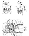
Figures 1 and3 are respective axial cross sections of a pulley assembly according to the present invention in two respective conditions of operation; -
Figures 2 and4 illustrate an enlarged detail of the pulley assembly ofFigures 1 and3 according to the view indicated by arrow F; -
Figures 5 ,7 and9 are respective axial cross sections of a second embodiment of the present invention in three respective conditions of operation; -
Figures 6 ,8 and10 illustrate enlarged details of the pulley assembly ofFigures 5 ,7 , and9 according to the view indicated by arrow F; and -
Figures 11 and 12 are respective axial cross sections of a third embodiment of the present invention in two respective conditions of operation. - Designated by the reference number 1 in
Figure 1 is a pulley assembly comprising ahub 2, which has an axis A and is designed to be connected to a crankshaft of an internal-combustion engine, apulley 3, connected to thehub 2 via abearing 4, and aseismic ring 5, connected to thehub 2 via aband 6 made of elastomeric material so as to define a dynamic damper of torsional vibrations. - In particular, the
hub 2 is made of a single body of metal plate and has, at respectively increasing concentric diameters, aflange 7, defining holes 8 for connection to the crankshaft, a supportingportion 9, having an L-shaped longitudinal section coming axially out from theflange 7 and defining a seat 10 for thebearing 4, and a C-shaped portion 11, coming axially out from the supportingportion 9. Thebearing 4 is axially closed in the seat 10 via an annular plate 7a connected to theflange 7. - The C-
shaped portion 11 defines acavity 12 having anaxial opening 13 facing the seat 10 and has acylindrical wall 14, coming axially out from the supportingportion 9, aside wall 15, transverse to the axis A for closing thecavity 12 on the opposite side of theopening 13, and acylindrical wall 16, radially external to thecylindrical wall 14 and axially extending up to theflange 7. - In addition, the
cylindrical wall 16 supports theband 6 on aface 17 thereof that is radially external with respect to thecavity 12 and has the same axial dimensions as theband 6 and theseismic ring 5. - In order to reduce the axial dimensions, the
pulley 3 is ringshaped with a substantially C-shaped cross section for housing the dynamic damper at least partially. - In particular, the
pulley 3 comprises atubular wall 18, mounted on the outer ring of thebearing 4, aside wall 19, which is transverse to the axis A and faces axially theopening 13, and acrown wheel 20, which surrounds at least one axial portion of theseismic ring 5 and defines a plurality ofgrooves 20a designed to co-operate with a belt of a drive (not illustrated). - The pulley assembly 1 further comprises a
band clutch 21, which co-operates between thehub 2 and thepulley 3 within theslot 12 and is governed by anelectromagnet 22 fixedly connected to a wall of the internal-combustion engine facing in use the pulley assembly 1. - In particular, the
band clutch 21 comprises acoil element 23, wound on both thecylindrical wall 14 and thetubular wall 18, anelectromagnetic armature 24, which co-operates with thecoil element 23 and is axially mobile under the action of theelectromagnet 22, and ahelical spring 25, which surrounds thecoil element 23 and is set so as to exert an axial load on thearmature 24. - The
armature 24 has atubular portion 26 housed in thecavity 12 and aflange 28 coming out radially from thecylindrical wall 27 and axially set between theseismic ring 5 and theside wall 19. - In particular, the
tubular portion 26 comprises anend wall 27, which is axially opposite to theflange 28 and is set between thecoil element 23 and theside wall 15. Theend wall 27 co-operates directly with thehelical spring 25 and is pushed by the latter against theside wall 15. - The
coil element 23 comprises anend portion 29, rigidly constrained to theside wall 19 via apin 30, and anend portion 31, which is axially opposite to theend portion 29 and is connected to theend wall 27 of thearmature 24. - In particular, the
end portion 31 carries anaxial pin 32, which is slidably housed in agroove 33 defined by theend wall 27. Thegroove 33 defines a path with respect to the axis A having a radial height decreasing as the angular position increases, where the angular position is considered as increasing when it has same direction of winding of thecoil element 23 viewed from the direction indicated by the arrow F inFigure 1 . - In addition, the
coil element 23 has a plurality of turns with a flattened rectangular cross section, which wind oncylindrical surfaces cylindrical wall 14 and by thetubular wall 18. Preferably, thecylindrical surface 34 and thecylindrical surface 35 have the same diameter. -
Figures 5 to 10 illustrate cross sections of a second embodiment of the present invention, in which elements that correspond or are functionally identical to the ones already used in the description of the pulley assembly 1 are designated by the same reference numbers. - The pulley assembly of
Figure 5 , designated by 51, has ahub 2, defining the supportingportion 9 for housing thebearing 4, and the C-shaped portion 11, defining thecavity 12 via thecylindrical wall 14, theside wall 15, and thecylindrical wall 16. Thecylindrical wall 16 supports theelastomeric band 6 and theseismic ring 5. In thepulley assembly 51, however, thecylindrical walls - The
pulley assembly 51 further comprises: apulley 53, which has a C-shapedannular portion 54, connected to thebearing 4; and a supportingwall 55, which comes radially out from theannular portion 54 on the opposite side of thebearing 4 and is connected to thecrown wheel 20 in a position corresponding to the median plane of the latter. - In particular, the
annular portion 54 comprises twotubular walls side wall 58 so as to define acavity 59 having the same mean diameter as that of thecavity 12 and facing the latter. - The
band clutch 21 is housed withincavities coil element 23, acoil element 60, which surrounds thecoil element 23 and co-operates withcylindrical surfaces cylindrical wall 16 and thetubular wall 57, and anelectromagnetic armature assembly 61 kept in a predetermined position by thehelical spring 25. - In particular, the
electromagnetic armature assembly 61 comprises aflanged element 62, which is made of ferromagnetic metal plate and slides axially on an outer surface of thetubular wall 57, and aring 63, which is housed within thecavity 12 and is pressed against theside wall 19 via thehelical spring 25. The flangedelement 62 and theseismic ring 5 are partially surrounded by thecrown wheel 20 and are located on respective axially opposite sides of the supportingwall 55. Theelectromagnetic armature assembly 61 further comprises a plurality of beam-like elements 64 (Figure 7 ), which slide withinrespective holes 65 defined on theside wall 58 and arranged so as to connect rigidly, in an axial direction, thering 63 to theflanged element 62. - In addition, the
coil elements respective end portions side wall 58 viarespective pins 30 and 67 (Figures 5 and9 ). - The
coil element 23 is connected to thering 63 via theaxial pin 32, which is able to slide within the groove 33 (Figure 6b ), and thecoil element 60 is likewise connected to thering 63 via anaxial pin 68, which slides within agroove 69 and is carried by anend portion 70 of thecoil element 60 opposite to the end portion 66 (Figure 6a ). - In particular, the
coil element 60 has the same direction of winding as that of thecoil element 23, and thegroove 69 has a radial height that decreases as the angular position increases, where the angular position is considered to increase when it has the same direction of winding as thecoil element 60. - Preferably, the
grooves ring 63 in different angular positions, for example spaced by 180° to enable a greater compactness in the radial direction and balancing when rotating. -
Figure 11 illustrates moreover apulley assembly 79 according to a third embodiment, in which theband clutch 21 comprises asingle coil element 80, which co-operates alternatively with thecylindrical surfaces cylindrical surfaces - The elements of the
pulley assembly 79 that functionally correspond to those of thepulley assemblies 1 and 51 are designated in what follows by the same reference numbers already used above. - In particular, the
pulley assembly 79 comprises thepulley 3 having a C-shaped cross section mounted on thehub 2 via thebearing 4. Thehub 2 has the C-shaped portion 11, in which thecylindrical walls - Within the
cavity 12 defined by the C-shaped portion 11, thehub 2 comprises aflange element 83 having anannular wall 84, rigidly connected to thecylindrical wall 16, atransverse wall 85, extending radially towards the centre of theannular wall 84, and atubular portion 86, coming axially out from thetransverse wall 85 on the opposite side of theannular wall 84 with respect to thetransverse wall 85. - The
tubular portion 86 is concentric to thecylindrical wall 14 and defines with the latter an annular compartment, which is delimited at the top by thecylindrical surface 81 and houses an axial portion of thecoil element 80. Thecoil element 80 has aflanged end portion 87 axially set between theside wall 15 and thetransverse wall 85. - The
pulley assembly 79 further comprises anannular armature 88, which co-operates with theflanged end portion 87, and a Belleville washer 89, which rests against theside wall 15 and co-operates with theannular armature 88 so as to press theflanged end portion 87 against thetransverse wall 85. - On the axially opposite side of the flanged
end portion 87, thecoil element 80 presents theend portion 29 rigidly connected to theside wall 19. In addition, thepulley 3 comprises a funnel-shapedelement 90, which integrally has aflange 91 rigidly connected to theside wall 19, and atubular portion 92, which comes out from theflange 89 and defines thecylindrical surface 82. In particular, thetubular portion 92 is concentric to thetubular wall 19 and defines an annular compartment for housing the remaining axial portion of thecoil element 80. - Operation of the pulley assembly 1 is described in what follows.
- During operation of the internal-combustion engine, the belt drive for accessories is driven via the crankshaft, and the band clutch is closed in such a way that the
hub 2 and thepulley 3 are rotationally fixed to one another. Theaxial pin 32 is located so that it bears upon an end-of-travel 33b defined by the groove 33 (Figure 2 ), and thearmature 24 is kept fixed to thehub 2 by friction against theside wall 15 via the action of thehelical spring 25. In this way, both of theaxial end portions respective hub 2 andpulley 3. In addition, thecoil element 23 has a direction of winding of the coil such that, in the condition of operation where thehub 2 tends to overrun thepulley 3, the turns tend to tighten and grip on thecylindrical surfaces hub 2 andpulley 3 rotationally fixed to one another. - When the vehicle is stationary, for example waiting at the traffic lights, the electronic control.unit turns off the engine, and the transmission is driven by the reversible electric machine. Accordingly, the electronic control unit energises the
electromagnet 22, which decouples thearmature 24 from thehub 2 against the action of the helical spring 25 (Figure 3 ) and enables thepulley 3 to rotate idle guided by thebearing 4. - Following upon the movement of recession of the
armature 24, thecoil element 23 tends to unwind sufficiently to cause a radial expansion of the turns and decouples from thecylindrical surface 34 so as to enable free rotation of thepulley 3 with respect to thehub 2. It is possible to exploit the elastic return of thecoil element 23 in order to favour its unwinding by appropriately sizing the geometry of thegroove 33. In fact, after decoupling of thearmature 24 from thehub 2, theend portion 31 of thecoil element 23 tends to unwind and moves in the direction of thearrest 33a (Figure 4 ). Thegroove 33 has a variable radial height and consequently guides the radial movement of theend portion 31 and facilitates decoupling. - When the accelerator pedal is pressed, the electronic control unit starts the engine via the starting motor connected to the fly-wheel of the crankshaft. Following upon starting of the engine, the electronic control unit interrupts energization of the
electromagnet 22 when the tangential velocity of thehub 2 and of thepulley 3 are equal. Consequently, thearmature 24 is pushed against thehub 2 by thehelical spring 25 and starts to rotate rigidly with the latter. Theaxial pin 32 slides along thegroove 33 towards the end-of-travel 33b (Figure 2 ), and theaxial end portion 31 approaches thecylindrical surface 34. When theaxial end portion 34 comes into contact with thecylindrical surface 34 or else with the end-of-travel 33b, it becomes rotationally fixed to thehub 2 and tends to wind up thecoil element 23 on thecylindrical surfaces band clutch 21 closes, and thehub 2 draws the belt drive for accessories. At the same time, the electronic control unit switches operation of the reversible electric machine into the alternator mode. - The
pulley assembly 51 is used on engines in which the reversible electric machine also performs the function of starting motor. - In particular, when the engine drives the belt drive, the
coil element 23 functions as described previously. In addition, thecoil element 60 is simultaneously decoupled from thecylindrical surfaces grooves Figures 6a, 6b ). - When the belt drive for accessories is driven by the reversible electric machine, the
armature assembly 61 recedes towards thepulley 53 and compresses both of thecoil elements coil element 23 is decoupled as described previously (Figure 7 ). - At the same time, since compression of the
coil elements coil element 60 tends to approach thecylindrical surface 81, which is an internal cylindrical surface that surrounds thecoil element 60. Furthermore, the geometry of thegrooves coil elements - When the accelerator pedal is pressed, the reversible electric machine slows down until it stops, the electronic control unit issues a command for interruption of the current to the
electromagnet 22, and thehelical spring 25 brings thearmature assembly 61 to bear upon the hub 2 (Figure 9 ). - Consequently, the
armature assembly 61 is rotationally fixed to thehub 2 and, in this case, the driving torque is applied to thepulley 53 in order to start the crankshaft via thehub 2. - In this condition, the speed of the
pulley 53 tends to exceed that of thehub 2, and this causes an unwinding of both of thecoil elements axial end portions travel Figures 10a, 10b ). In particular, thecoil element 23 moves away from thecylindrical surfaces coil element 60 couples by friction against thecylindrical surfaces - Consequently, the
pulley 53 is rotationally fixed to thehub 2, and the crankshaft is driven in rotation. Coupling is moreover favoured by the geometry of thegroove 69, which, in the case of unwinding of thecoil element 60, tends to approach theend portion 66 towards thecylindrical surface 81. - When the engine is started, the engine torque increases until it exceeds that of the reversible electric machine.
- In this case, as has already been described, the
hub 2 tends to overtake thepulley 53. Consequently, thecoil elements coil element 23 couples again with thecylindrical surfaces pulley 53 rotationally fixed to the hub 2 (Figure 5 ). - Simultaneously, also the
coil element 60 winds up and consequently decouples from thecylindrical surfaces pin 67 carried by theend portion 66 bears upon the end-of-travel 69b. - The
pulley assembly 79 functions in a way similar to thepulley assembly 51 but uses asingle coil element 80. In particular, when the engine drives the belt drive, thecoil element 80 is coupled to thecylindrical surfaces coil element 23. - When the belt drive is driven via the reversible electric machine, the
annular armature 88 recedes under the action of theelectromagnet 22, and theflanged end portion 87 separates itself from thetransverse wall 85. Consequently, thecoil element 80 re-establish its own undeformed configuration and decouples from thecylindrical surface 34. - When the engine is started via the reversible electric machine, the
electromagnet 22 is disabled, and theBelleville washer 89 pushes both theannular armature 88 and theflanged end portion 87 against thetransverse wall 85. In this way, theflanged end portion 87 is rotationally fixed to thehub 2. Consequently, when the driving torque comes from the belt drive and thepulley 3 tends to overtake thehub 2, thecoil element 80 winds up and couples by friction against thecylindrical surfaces - After the engine is started and the reversible electric machine is switched into the alternator mode, the driving torque comes from the crankshaft, and the
hub 2 tends to overtake thepulley 3. - Consequently, the elastic element tends to wind up and decouples from the
cylindrical surfaces cylindrical surfaces hub 2 rotationally fixed to thepulley 3. - The advantages that the
pulley assemblies - The use of a band clutch enables transmission of high torques with reduced radial dimensions and without the use of axial springs of large dimensions.
- In addition, via appropriate sizing of the times of coupling of the
band clutch 21, it is possible to obtain a damping of the high vibrations during the first instants of starting of the internal-combustion engine and/or provide rotational coupling of the crankshaft only after the starting transient of the engine. - Use of a band clutch has moreover proven adequate to enable correct operation of the dynamic damper integrated on the
hub 2. - The
grooves coil elements surfaces - The
helical spring 25 and theBelleville washer 89 exert smaller axial forces and are consequently of contained dimensions. For the same reason, the current necessary for countering their action is reduced. - Finally, it is clear that modifications and variations may be made to the hub-pulley assemblies described and illustrated herein, without thereby departing from the sphere of protection of the present invention, as defined in the annexed claims.
- The
pulley assemblies 1 and 51 can haveend portions 31 having a flange similar to theend portion 87. Likewise, theannular armature 88 can have a groove similar to thegroove 33, and theend portion 87 can carry an axial pin coupling with the groove. - Furthermore, it may be envisaged that the
coil elements end portions hub 2 and modifying thearmatures - It is possible to modify the direction of rotation of the
coil elements grooves pulley assembly 51 so as to obtain that thecoil element 60 will be coupled with thecylindrical surfaces hub 2 tends to overtake thepulley 53 and, vice versa, will be coupled to thecylindrical surfaces pulley 53 tends to overtake thehub 2. - Also the
pulley assemblies 1 and 79 can be modified in this sense. - In addition, the axial action exerted by the
helical spring 25 and by theBelleville washer 89 can be obtained via an appropriate axial preloading of thecoil elements
Claims (20)
- A pulley assembly (1; 51; 79) for a start-stop belt drive, comprising a hub (2) having an axis (A) and designed to be connected to a crankshaft of an internal-combustion engine, a pulley (3; 53) designed to co-operate with a belt of a belt drive and supported in a rotatable way by said hub (2) through a bearing (4), and a seismic mass (5) connected to said hub (2), so as to rotate with respect to said hub (2) for defining a dynamic damping device for damping the torsional vibrations, said pulley assembly being characterized in that it comprises a band clutch (21), which co-operates selectively between said hub (2) and said pulley (3; 53) and comprises a coil element (23; 80) and electromagnetic actuation means (24; 61; 88) co-operating with said coil element (23; 80) and mobile between a coupling position in which said band clutch (21) is closed and said hub (2) is rotationally fixed to said pulley (3; 53) when said hub (2) tends to overtake said pulley (3; 53), and a position of decoupling in which said band clutch (21) is open and said pulley (3; 53) turns idle on said hub (2), and in that said band clutch (21) is at least partially housed in a cavity (12) defined by said hub (2) in a position radially lower than that of said seismic mass (5).
- The pulley assembly according to Claim 1, characterized in that said coil element (23; 80) comprises a first axial end portion (29) permanently constrained to one between said hub (2) and said pulley (3; 53), and a second axial end portion (31; 87), opposite to said first axial end portion (29), co-operating with said electromagnetic actuation means (24; 61; 88).
- The pulley assembly according to Claim 2, characterized in that it comprises guide means (32, 33; 68, 69), which are set between said second axial end portion (31) and said electromagnetic actuation means (24; 61; 88) and are configured so as to vary the radial position of said axial end portion (31) in response to a relative rotation between said second end portion (31; 66) and said electromagnetic actuation means (24; 61) for closing said band clutch (21).
- The pulley assembly according to Claim 3, characterized in that said guide means define a groove (33) carried by said electromagnetic actuation means (24; 61), and a pin (32) carried by said second axial end portion (31) and slidably housed in said groove (33).
- The pulley assembly according to any one of Claims 2 to 4, characterized in that said first axial end portion (29) is constrained to said pulley (3; 53) and in that said hub (2) and said pulley (3; 53) define a first cylindrical surface (34) and a second cylindrical surface (35), respectively, which share said axis (A) and co-operate selectively with said coil element (23; 80).
- The pulley assembly according to Claim 5, characterized in that said first and second cylindrical surfaces (34, 35) are surrounded by said coil element (23; 80).
- The pulley assembly according to any one of the preceding claims, characterized in that said electromagnetic actuation means (24) are axially set between said hub (2) and said pulley (3).
- The pulley assembly according to any one of Claims 1 to 6, characterized in that said band clutch (21) comprises a second coil element (60) co-operating with said electromagnetic coupling means (61) for rendering said hub (2) rotationally fixed to said pulley (53) in response to a relative rotation between said hub (2) and said pulley (53) in a second predetermined direction opposite to said predetermined direction.
- The pulley assembly according to Claim 8, characterized in that said second coil element (60) comprises a third axial end portion (29) permanently constrained to one between said hub (2) and said pulley (53), and a fourth axial end portion (70) opposite to said third axial end portion (29) and co-operating with said electromagnetic actuation means (61).
- The pulley assembly according to Claim 9, characterized in that it comprises guide means (68, 69) set between said fourth axial end portion (70) and said electromagnetic actuation means (61) and configured so as to vary the radial position of said axial end portion (70) in response to a relative rotation between said fourth axial end portion (70) and said electromagnetic actuation means (61) for closing said band clutch (21).
- The pulley assembly according to Claim 10, characterized in that said guide means define a second groove (69) carried by said electromagnetic actuation means (61), and a second pin (68) carried by said fourth end portion (70) and slidably housed in said second groove (69).
- The pulley assembly according to any one of Claims 9 to 11, characterized in that said third axial end portion (29) is constrained to said pulley (53) and in that said hub (2) and said pulley (53) define, respectively, a third cylindrical surface (81) and a fourth cylindrical surface (82), which are, respectively, concentric to said first and second cylindrical surfaces (34, 35) and surround said second coil element (60).
- The pulley assembly according to Claim 12, characterized in that said electromagnetic actuation means (61) comprise an armature (62) slidably supported by said pulley (53).
- The pulley assembly according to Claim 13, characterized in that said pulley (53) is axially set between said armature (62) and said hub (2) and in that said electromagnetic actuation means (61) comprise a supporting element (63) axially set between said hub (2) and said pulley (53), and a plurality of beam-like elements (64), which are connected in an axially rigid way between said armature (62) and said supporting element (63) and slide in respective holes (65) defined by said hub (2).
- The pulley assembly according to Claim 2, characterized in that at least one between said hub (2) and said pulley (3) defines a first coupling surface (34, 81) and a second coupling surface (35, 82) set at a radial distance from one another and in that said coil element (80) is radially set between said first coupling surface (34, 81) and said second coupling surface (35, 82) and co-operates selectively with said first and second coupling surfaces (34, 81; 35, 82) in said coupling position.
- The pulley assembly according to Claim 15, characterized in that said second axial end portion (87) is flanged and co-operates by friction against a transverse wall (85) of one between said hub (2) and said pulley (3) in said coupling position.
- The pulley assembly according to Claim 16, characterized in that said electromagnetic actuation means (88) comprise an annular armature co-operating axially with said second axial end portion (87).
- The pulley assembly according to any one of the preceding claims, characterized in that it comprises elastic means (25; 89) co-operating axially with said electromagnetic actuation means (24; 61; 88) for maintaining said coupling position.
- The pulley assembly according to any one of Claims 1 to 17, characterized in that said electromagnetic actuation means (24; 61; 88) are maintained in said coupling position via a thrust exerted axially by said coil element (23; 80).
- The pulley assembly according to any one of the preceding claims, characterized in that said cavity (12) is axially closed by said pulley (3; 53).
Applications Claiming Priority (1)
| Application Number | Priority Date | Filing Date | Title |
|---|---|---|---|
| PCT/IT2006/000173 WO2007108020A1 (en) | 2006-03-21 | 2006-03-21 | Pulley assembly for a start-stop belt drive |
Publications (3)
| Publication Number | Publication Date |
|---|---|
| EP2002137A1 EP2002137A1 (en) | 2008-12-17 |
| EP2002137B1 true EP2002137B1 (en) | 2011-03-09 |
| EP2002137B8 EP2002137B8 (en) | 2011-09-21 |
Family
ID=37408622
Family Applications (1)
| Application Number | Title | Priority Date | Filing Date |
|---|---|---|---|
| EP06728500A Not-in-force EP2002137B8 (en) | 2006-03-21 | 2006-03-21 | Pulley assembly for a start-stop belt drive |
Country Status (4)
| Country | Link |
|---|---|
| US (1) | US8182382B2 (en) |
| EP (1) | EP2002137B8 (en) |
| DE (1) | DE602006020635D1 (en) |
| WO (1) | WO2007108020A1 (en) |
Cited By (1)
| Publication number | Priority date | Publication date | Assignee | Title |
|---|---|---|---|---|
| DE102013108839A1 (en) | 2012-08-20 | 2014-02-20 | Miba Sinter Austria Gmbh | Belt pulley arrangement for dual-belt drive system, has coupling unit with two coupling elements, where coupling elements are connected with belt pulleys, and are connected with each other in form-fit manner |
Families Citing this family (12)
| Publication number | Priority date | Publication date | Assignee | Title |
|---|---|---|---|---|
| US8056688B2 (en) | 2007-12-14 | 2011-11-15 | Reell Precision Manufacturing Corporation | Immersed wrap spring device |
| CA2801096A1 (en) * | 2010-06-16 | 2011-12-22 | Litens Automotive Partnership | Clutch for selectively driving an accessory |
| ITTO20110299A1 (en) * | 2011-04-01 | 2012-10-02 | Dayco Europe Srl | DETACHABLE PULLEY FOR A BELT OR CHAIN TRANSMISSION |
| ITTO20110300A1 (en) * | 2011-04-01 | 2012-10-02 | Dayco Europe Srl | DETACHABLE PULLEY FOR A BELT OR CHAIN TRANSMISSION |
| EP2592296B1 (en) * | 2011-11-09 | 2014-01-15 | Aisin Seiki Kabushiki Kaisha | Electromagnetic clutch |
| JP5884417B2 (en) * | 2011-11-09 | 2016-03-15 | アイシン精機株式会社 | Electromagnetic clutch |
| EP2836733B1 (en) * | 2012-04-10 | 2019-01-02 | Litens Automotive Partnership | Clutch assembly |
| ITTO20120358A1 (en) * | 2012-04-23 | 2013-10-24 | Dayco Europe Srl | ENGINEERED ENGAGEMENT FOR AN INTERNAL COMBUSTION ENGINE ACCESSORY |
| US9051911B2 (en) * | 2012-04-30 | 2015-06-09 | GM Global Technology Operations LLC | Engine crankshaft isolator assembly |
| US9182028B2 (en) | 2013-02-08 | 2015-11-10 | Motorcar Parts Of America, Inc. | Torsional impact damping and decoupling pulley |
| DE102018128641B4 (en) * | 2018-11-15 | 2024-03-28 | Schaeffler Technologies AG & Co. KG | Pulley decoupler with a toothing, auxiliary drive and drive motor with a corresponding pulley decoupler and method for producing a corresponding pulley decoupler |
| IT202000009289A1 (en) * | 2020-04-28 | 2021-10-28 | Dayco Europe Srl | IMPROVED FILTER PULLEY |
Family Cites Families (8)
| Publication number | Priority date | Publication date | Assignee | Title |
|---|---|---|---|---|
| AU4791279A (en) | 1978-06-12 | 1979-12-20 | Diesel Kiki Co. Ltd. | Clutch |
| GB2034830B (en) * | 1978-10-13 | 1982-10-20 | Servicon Clutches Ltd | Wrap spring clutches |
| JPS57101129A (en) * | 1980-12-16 | 1982-06-23 | Ogura Clutch Co Ltd | Electromagnetic spring clutch |
| JPS588833A (en) * | 1981-07-10 | 1983-01-19 | Nippon Denso Co Ltd | Electromagnetic spring clutch |
| JP4892756B2 (en) * | 2000-10-12 | 2012-03-07 | シェフラー テクノロジーズ ゲゼルシャフト ミット ベシュレンクテル ハフツング ウント コンパニー コマンディートゲゼルシャフト | Transmission |
| AU2003232546A1 (en) | 2002-06-10 | 2003-12-22 | Litens Automotive | Overrunning enabled automotive starter/generator |
| WO2004070225A1 (en) * | 2003-02-04 | 2004-08-19 | Litens Automotive | Crankshaft torque modulator |
| DE10305312A1 (en) | 2003-02-10 | 2004-09-23 | Steinbrunn, Marc Boris, Dr. | Insulation jacket in the area of the pipe suspension |
-
2006
- 2006-03-21 US US12/293,605 patent/US8182382B2/en not_active Expired - Fee Related
- 2006-03-21 DE DE602006020635T patent/DE602006020635D1/en active Active
- 2006-03-21 WO PCT/IT2006/000173 patent/WO2007108020A1/en not_active Ceased
- 2006-03-21 EP EP06728500A patent/EP2002137B8/en not_active Not-in-force
Cited By (1)
| Publication number | Priority date | Publication date | Assignee | Title |
|---|---|---|---|---|
| DE102013108839A1 (en) | 2012-08-20 | 2014-02-20 | Miba Sinter Austria Gmbh | Belt pulley arrangement for dual-belt drive system, has coupling unit with two coupling elements, where coupling elements are connected with belt pulleys, and are connected with each other in form-fit manner |
Also Published As
| Publication number | Publication date |
|---|---|
| US8182382B2 (en) | 2012-05-22 |
| DE602006020635D1 (en) | 2011-04-21 |
| WO2007108020A1 (en) | 2007-09-27 |
| US20100234156A1 (en) | 2010-09-16 |
| EP2002137A1 (en) | 2008-12-17 |
| EP2002137B8 (en) | 2011-09-21 |
Similar Documents
| Publication | Publication Date | Title |
|---|---|---|
| EP2002137B1 (en) | Pulley assembly for a start-stop belt drive | |
| CN103946576B (en) | Isolation separator of alternating-current generator | |
| US7901310B2 (en) | Two-arm belt tensioner for a belt drive | |
| EP2855957B1 (en) | Isolator decoupler | |
| JP4839319B2 (en) | Recirculation pump actuator for cooling circuit of internal combustion engine | |
| EP3027925B1 (en) | Crankshaft isolating decoupler | |
| WO2015112403A2 (en) | Isolating decoupler | |
| CN104379957B (en) | Clutch device having an actuating device | |
| CN101855688B (en) | A transmission device for a circuit breaker with a freewheel coupling device | |
| KR102201129B1 (en) | Accessory belt drive system with multiple ratios and torque reversals | |
| US7488271B2 (en) | Control method of magnet type fan clutch | |
| EP2715171A1 (en) | Isolator decoupler | |
| US8733190B2 (en) | Starter machine system and method | |
| MX2008011512A (en) | Variable ratio belt drive system. | |
| US20130152730A1 (en) | Dual Mass Flywheel Assembly | |
| KR20170055504A (en) | Crank isolating pulley | |
| EP2694844B1 (en) | Decouplable pulley for a belt or chain drive | |
| EP2011999B1 (en) | Speed reduction type starter for engines | |
| US4482038A (en) | Double active drive mechanism | |
| JPH02502114A (en) | fan clutch | |
| ITTO20100394A1 (en) | DAMPING PULLEY GROUP | |
| AU2019364211A1 (en) | Tensioner | |
| JPH0610815A (en) | Starter for internal combustion engine | |
| EP4143462B1 (en) | Improved filtering pulley | |
| WO2012131662A1 (en) | Decouplable pulley for a belt or chain drive |
Legal Events
| Date | Code | Title | Description |
|---|---|---|---|
| PUAI | Public reference made under article 153(3) epc to a published international application that has entered the european phase |
Free format text: ORIGINAL CODE: 0009012 |
|
| 17P | Request for examination filed |
Effective date: 20081021 |
|
| AK | Designated contracting states |
Kind code of ref document: A1 Designated state(s): DE FR GB IT |
|
| 17Q | First examination report despatched |
Effective date: 20090122 |
|
| DAX | Request for extension of the european patent (deleted) | ||
| RBV | Designated contracting states (corrected) |
Designated state(s): DE FR GB IT |
|
| GRAP | Despatch of communication of intention to grant a patent |
Free format text: ORIGINAL CODE: EPIDOSNIGR1 |
|
| GRAS | Grant fee paid |
Free format text: ORIGINAL CODE: EPIDOSNIGR3 |
|
| 111Z | Information provided on other rights and legal means of execution |
Free format text: DE FR GB IT Effective date: 20101005 |
|
| GRAA | (expected) grant |
Free format text: ORIGINAL CODE: 0009210 |
|
| AK | Designated contracting states |
Kind code of ref document: B1 Designated state(s): DE FR GB IT |
|
| REG | Reference to a national code |
Ref country code: GB Ref legal event code: FG4D |
|
| 111Z | Information provided on other rights and legal means of execution |
Free format text: DE FR GB IT Effective date: 20110216 |
|
| REF | Corresponds to: |
Ref document number: 602006020635 Country of ref document: DE Date of ref document: 20110421 Kind code of ref document: P |
|
| REG | Reference to a national code |
Ref country code: DE Ref legal event code: R096 Ref document number: 602006020635 Country of ref document: DE Effective date: 20110421 |
|
| RAP2 | Party data changed (patent owner data changed or rights of a patent transferred) |
Owner name: DAYCO EUROPE S.R.L. |
|
| PLBE | No opposition filed within time limit |
Free format text: ORIGINAL CODE: 0009261 |
|
| STAA | Information on the status of an ep patent application or granted ep patent |
Free format text: STATUS: NO OPPOSITION FILED WITHIN TIME LIMIT |
|
| 26N | No opposition filed |
Effective date: 20111212 |
|
| REG | Reference to a national code |
Ref country code: DE Ref legal event code: R097 Ref document number: 602006020635 Country of ref document: DE Effective date: 20111212 |
|
| REG | Reference to a national code |
Ref country code: DE Ref legal event code: R082 Ref document number: 602006020635 Country of ref document: DE Representative=s name: FRANK OPPERMANN, DE Ref country code: DE Ref legal event code: R082 Ref document number: 602006020635 Country of ref document: DE Representative=s name: OPPERMANN, FRANK, DIPL.-ING., DE |
|
| REG | Reference to a national code |
Ref country code: FR Ref legal event code: PLFP Year of fee payment: 11 |
|
| PGFP | Annual fee paid to national office [announced via postgrant information from national office to epo] |
Ref country code: FR Payment date: 20160208 Year of fee payment: 11 Ref country code: GB Payment date: 20160316 Year of fee payment: 11 |
|
| GBPC | Gb: european patent ceased through non-payment of renewal fee |
Effective date: 20170321 |
|
| REG | Reference to a national code |
Ref country code: FR Ref legal event code: ST Effective date: 20171130 |
|
| PG25 | Lapsed in a contracting state [announced via postgrant information from national office to epo] |
Ref country code: FR Free format text: LAPSE BECAUSE OF NON-PAYMENT OF DUE FEES Effective date: 20170331 |
|
| PG25 | Lapsed in a contracting state [announced via postgrant information from national office to epo] |
Ref country code: GB Free format text: LAPSE BECAUSE OF NON-PAYMENT OF DUE FEES Effective date: 20170321 |
|
| PGFP | Annual fee paid to national office [announced via postgrant information from national office to epo] |
Ref country code: IT Payment date: 20200303 Year of fee payment: 15 |
|
| PGFP | Annual fee paid to national office [announced via postgrant information from national office to epo] |
Ref country code: DE Payment date: 20200330 Year of fee payment: 15 |
|
| REG | Reference to a national code |
Ref country code: DE Ref legal event code: R119 Ref document number: 602006020635 Country of ref document: DE |
|
| PG25 | Lapsed in a contracting state [announced via postgrant information from national office to epo] |
Ref country code: DE Free format text: LAPSE BECAUSE OF NON-PAYMENT OF DUE FEES Effective date: 20211001 |
|
| PG25 | Lapsed in a contracting state [announced via postgrant information from national office to epo] |
Ref country code: IT Free format text: LAPSE BECAUSE OF NON-PAYMENT OF DUE FEES Effective date: 20210321 |