EP2002109B1 - Fördereinheit - Google Patents
Fördereinheit Download PDFInfo
- Publication number
- EP2002109B1 EP2002109B1 EP08708464A EP08708464A EP2002109B1 EP 2002109 B1 EP2002109 B1 EP 2002109B1 EP 08708464 A EP08708464 A EP 08708464A EP 08708464 A EP08708464 A EP 08708464A EP 2002109 B1 EP2002109 B1 EP 2002109B1
- Authority
- EP
- European Patent Office
- Prior art keywords
- supporting elements
- delivery unit
- fuel
- swirl pot
- flange
- Prior art date
- Legal status (The legal status is an assumption and is not a legal conclusion. Google has not performed a legal analysis and makes no representation as to the accuracy of the status listed.)
- Not-in-force
Links
- 239000000446 fuel Substances 0.000 claims abstract description 15
- 239000004033 plastic Substances 0.000 claims abstract description 9
- 229920003023 plastic Polymers 0.000 claims abstract description 9
- 239000000463 material Substances 0.000 claims abstract description 5
- 238000002485 combustion reaction Methods 0.000 claims abstract description 4
- 239000002828 fuel tank Substances 0.000 claims description 10
- OKTJSMMVPCPJKN-UHFFFAOYSA-N Carbon Chemical compound [C] OKTJSMMVPCPJKN-UHFFFAOYSA-N 0.000 claims description 3
- 239000004952 Polyamide Substances 0.000 claims description 3
- 229910052799 carbon Inorganic materials 0.000 claims description 3
- 229920002647 polyamide Polymers 0.000 claims description 3
- 229930040373 Paraformaldehyde Natural products 0.000 claims description 2
- -1 polyoxymethylene Polymers 0.000 claims description 2
- 229920006324 polyoxymethylene Polymers 0.000 claims description 2
- 239000004071 soot Substances 0.000 claims description 2
- 239000002071 nanotube Substances 0.000 claims 1
- 239000002184 metal Substances 0.000 description 3
- 238000003780 insertion Methods 0.000 description 2
- 230000037431 insertion Effects 0.000 description 2
- 230000003068 static effect Effects 0.000 description 2
- 239000006229 carbon black Substances 0.000 description 1
- 239000002041 carbon nanotube Substances 0.000 description 1
- 238000001746 injection moulding Methods 0.000 description 1
- 238000009434 installation Methods 0.000 description 1
- 239000007788 liquid Substances 0.000 description 1
- 238000004519 manufacturing process Methods 0.000 description 1
- 230000002787 reinforcement Effects 0.000 description 1
- 239000007787 solid Substances 0.000 description 1
Images
Classifications
-
- F—MECHANICAL ENGINEERING; LIGHTING; HEATING; WEAPONS; BLASTING
- F02—COMBUSTION ENGINES; HOT-GAS OR COMBUSTION-PRODUCT ENGINE PLANTS
- F02M—SUPPLYING COMBUSTION ENGINES IN GENERAL WITH COMBUSTIBLE MIXTURES OR CONSTITUENTS THEREOF
- F02M37/00—Apparatus or systems for feeding liquid fuel from storage containers to carburettors or fuel-injection apparatus; Arrangements for purifying liquid fuel specially adapted for, or arranged on, internal-combustion engines
- F02M37/04—Feeding by means of driven pumps
- F02M37/08—Feeding by means of driven pumps electrically driven
- F02M37/10—Feeding by means of driven pumps electrically driven submerged in fuel, e.g. in reservoir
- F02M37/103—Mounting pumps on fuel tanks
-
- B—PERFORMING OPERATIONS; TRANSPORTING
- B60—VEHICLES IN GENERAL
- B60K—ARRANGEMENT OR MOUNTING OF PROPULSION UNITS OR OF TRANSMISSIONS IN VEHICLES; ARRANGEMENT OR MOUNTING OF PLURAL DIVERSE PRIME-MOVERS IN VEHICLES; AUXILIARY DRIVES FOR VEHICLES; INSTRUMENTATION OR DASHBOARDS FOR VEHICLES; ARRANGEMENTS IN CONNECTION WITH COOLING, AIR INTAKE, GAS EXHAUST OR FUEL SUPPLY OF PROPULSION UNITS IN VEHICLES
- B60K15/00—Arrangement in connection with fuel supply of combustion engines or other fuel consuming energy converters, e.g. fuel cells; Mounting or construction of fuel tanks
- B60K15/03—Fuel tanks
- B60K15/077—Fuel tanks with means modifying or controlling distribution or motion of fuel, e.g. to prevent noise, surge, splash or fuel starvation
-
- F—MECHANICAL ENGINEERING; LIGHTING; HEATING; WEAPONS; BLASTING
- F02—COMBUSTION ENGINES; HOT-GAS OR COMBUSTION-PRODUCT ENGINE PLANTS
- F02M—SUPPLYING COMBUSTION ENGINES IN GENERAL WITH COMBUSTIBLE MIXTURES OR CONSTITUENTS THEREOF
- F02M37/00—Apparatus or systems for feeding liquid fuel from storage containers to carburettors or fuel-injection apparatus; Arrangements for purifying liquid fuel specially adapted for, or arranged on, internal-combustion engines
- F02M37/04—Feeding by means of driven pumps
- F02M37/08—Feeding by means of driven pumps electrically driven
- F02M37/10—Feeding by means of driven pumps electrically driven submerged in fuel, e.g. in reservoir
- F02M37/106—Feeding by means of driven pumps electrically driven submerged in fuel, e.g. in reservoir the pump being installed in a sub-tank
Definitions
- the invention relates to a delivery unit for conveying fuel from a fuel tank to an internal combustion engine of a motor vehicle with a fuel pump, which is arranged in a swirl pot and a flange which closes an opening of the fuel tank, wherein the swirl pot with the flange via at least two support elements connected to the swirl pot.
- Such conveyor units have long been known and thus state of the art.
- the support elements are pressed by means of press fit in receiving bushes in the flange.
- the swirl pot has at its periphery corresponding guides in which the support elements are guided longitudinally displaceable.
- the supporting elements surrounding coil springs which are supported at one end on the respective support member or on the flange and the other end of the swirl pot, cause the swirl pot is biased against the bottom of the fuel tank. Due to specified safety regulations, metal parts with a capacity greater than 3 pF must be protected against static charges. This means that the metal pipes must be earthed, which increases the cost of the conveyor unit.
- a conveyor unit which has a flange and a swirl pot.
- the swirl pot has guides in which connecting elements are arranged. In these fasteners engage metallic support elements.
- This type of support is characterized by a complex structure, which requires additional installation costs in addition to the increased production costs.
- the present invention is therefore based on the object to provide a conveyor unit with little effort.
- the object is achieved in that the support elements are pressed into sockets of the flange and consist of a fuel-resistant plastic, wherein the support elements are connected directly to the surge pot.
- the plastic for the support elements contains admixtures of carbon in the form of carbon black or nanotubes.
- baffle pot and in particular the guides for the support elements are also made of plastic, undesired noise may occur during movement of the support elements in the guides. Such noise is avoided when the plastic for the support elements contains admixtures of chalk.
- the attachment of the support elements is particularly simple when the support elements at its end facing the swirl pot at least one directed radially outward Have latching hooks.
- the at least one latching hook is reversibly deformed until it has passed the guide. Subsequently, it moves into its initial position, whereby the respective support element is secured against loosening from the guide. In this way, the support elements are particularly easy to assemble.
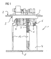
- FIG. 1 shows a conveyor unit 1 for use in a fuel tank 2 of a motor vehicle.
- the feed unit 1 consists of a flange 3 and a swirl pot 4.
- the flange 3 is designed so that it closes an opening 5 of the fuel tank 2, through which the feed unit 1 is inserted into the fuel tank 2.
- a fuel pump not shown, is arranged, which promotes fuel from the swirl pot 4 through the flange 3 to an internal combustion engine, not shown, of the motor vehicle.
- guides 13 are arranged, in each of which a support element 6 engages.
- Each support element 6 is surrounded by a helical spring 7.
- the coil springs 7 are supported on the flange 3 and on the guides 5 and cause in this way a bias of the baffle 4 against the bottom 8 of the fuel tank. 2
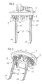
- FIGS. 2 and 3 show the flange 3 with the support elements 6.
- the support elements 6 To attach the support elements 6 has the flange bushes 9, in which the support elements 6 are pressed.
- the support elements 6 each have a collar 10 in the upper region, which is the insertion depth of the support elements 6 limited. At the same time, this ensures that each support element 6 is pressed in the same depth and thus the swirl pot is biased by the coil springs 7 against all latching hooks 11 at the lower end of the support elements 6 before the conveyor unit 1 is mounted in the fuel tank 2.
- the support elements 6 are made of polyamide. To avoid electrostatic charges carbon is added in the form of soot.
- the support elements 6 For mechanical reinforcement, the support elements 6 have axially extending webs 12. In addition, the webs 11 form a good guide for the coil springs.
Landscapes
- Engineering & Computer Science (AREA)
- Chemical & Material Sciences (AREA)
- Combustion & Propulsion (AREA)
- Mechanical Engineering (AREA)
- General Engineering & Computer Science (AREA)
- Life Sciences & Earth Sciences (AREA)
- Sustainable Development (AREA)
- Sustainable Energy (AREA)
- Transportation (AREA)
- Cooling, Air Intake And Gas Exhaust, And Fuel Tank Arrangements In Propulsion Units (AREA)
Applications Claiming Priority (3)
| Application Number | Priority Date | Filing Date | Title |
|---|---|---|---|
| DE102007007597 | 2007-02-13 | ||
| DE102008005358A DE102008005358A1 (de) | 2007-02-13 | 2008-01-21 | Fördereinheit |
| PCT/EP2008/051149 WO2008098840A1 (de) | 2007-02-13 | 2008-01-30 | Fördereinheit |
Publications (2)
| Publication Number | Publication Date |
|---|---|
| EP2002109A1 EP2002109A1 (de) | 2008-12-17 |
| EP2002109B1 true EP2002109B1 (de) | 2011-03-16 |
Family
ID=39597756
Family Applications (1)
| Application Number | Title | Priority Date | Filing Date |
|---|---|---|---|
| EP08708464A Not-in-force EP2002109B1 (de) | 2007-02-13 | 2008-01-30 | Fördereinheit |
Country Status (9)
| Country | Link |
|---|---|
| US (1) | US7819108B2 (ru) |
| EP (1) | EP2002109B1 (ru) |
| KR (1) | KR101097552B1 (ru) |
| CN (1) | CN101542102B (ru) |
| BR (1) | BRPI0803087A2 (ru) |
| DE (2) | DE102008005358A1 (ru) |
| ES (1) | ES2362555T3 (ru) |
| RU (1) | RU2410563C2 (ru) |
| WO (1) | WO2008098840A1 (ru) |
Families Citing this family (6)
| Publication number | Priority date | Publication date | Assignee | Title |
|---|---|---|---|---|
| KR101321937B1 (ko) * | 2012-03-13 | 2013-10-28 | 현담산업 주식회사 | 가이드로드 보강 커넥터가 구비된 연료펌프 모듈 |
| DE102013220885B4 (de) | 2013-10-15 | 2019-05-09 | Continental Automotive Gmbh | Fördereinheit und Verfahren zur Herstellung |
| US9539893B2 (en) * | 2014-09-29 | 2017-01-10 | Spectra Premium Industries Inc. | Fuel delivery module for low-profile fuel tank |
| JP6695707B2 (ja) | 2016-02-19 | 2020-05-20 | 愛三工業株式会社 | 燃料供給装置 |
| KR20170112333A (ko) * | 2016-03-31 | 2017-10-12 | 주식회사 케이엠에프 | 도전성을 갖는 연료펌프 필터장치 및 이를 제작하는 방법 |
| JP6992669B2 (ja) * | 2018-04-27 | 2022-01-13 | 株式会社デンソー | 燃料供給装置 |
Family Cites Families (27)
| Publication number | Priority date | Publication date | Assignee | Title |
|---|---|---|---|---|
| US4961693A (en) * | 1988-12-16 | 1990-10-09 | Walbro Corporation | Fuel pump isolation mount |
| US5482444A (en) * | 1994-09-06 | 1996-01-09 | General Motors Corporation | Vibration isolating mounting for an electric fuel pump |
| JP3640001B2 (ja) * | 1996-04-01 | 2005-04-20 | 株式会社デンソー | 燃料供給装置 |
| EP0969200B1 (en) * | 1997-03-11 | 2004-02-11 | Aisan Kogyo Kabushiki Kaisha | In-tank fuel filter improved to resist electrification |
| DE19843019C1 (de) * | 1998-09-19 | 2000-03-09 | Bosch Gmbh Robert | Fördereinrichtung für Kraftstoff |
| DE19915258C1 (de) * | 1999-04-03 | 2000-12-07 | Bosch Gmbh Robert | Gehäuse für eine mit einem Elektromotor angetriebene Förderpumpe |
| RU2165542C2 (ru) * | 1999-04-27 | 2001-04-20 | Открытое акционерное общество "АВТОВАЗ" | Модульный агрегат топливоподачи системы питания двигателя транспортного средства |
| RU2170362C2 (ru) * | 1999-05-19 | 2001-07-10 | Открытое акционерное общество "АВТОВАЗ" | Модульный агрегат топливоподачи системы питания двигателя транспортного средства |
| AT5218U1 (de) * | 1999-09-27 | 2002-04-25 | Tesma Motoren Getriebetechnik | Kraftstofftank |
| US6216671B1 (en) * | 1999-11-22 | 2001-04-17 | Delphi Technologies, Inc. | Modular fuel reservoir for motor vehicle |
| DE29922474U1 (de) * | 1999-12-22 | 2001-05-03 | Robert Bosch Gmbh, 70469 Stuttgart | Kraftstoffversorgungseinrichtung für eine Brennkraftmaschine eines Kraftfahrzeugs |
| JP2003172218A (ja) | 2001-12-06 | 2003-06-20 | Nissan Motor Co Ltd | 燃料タンクの燃料供給モジュール取付構造 |
| JP2003286925A (ja) * | 2002-03-27 | 2003-10-10 | Aisan Ind Co Ltd | 燃料供給装置 |
| JP3911434B2 (ja) * | 2002-04-03 | 2007-05-09 | 愛三工業株式会社 | リザーブ容器ユニット |
| JP2003293875A (ja) * | 2002-04-03 | 2003-10-15 | Aisan Ind Co Ltd | リザーブ容器ユニット |
| JP4243845B2 (ja) * | 2002-11-28 | 2009-03-25 | 株式会社デンソー | 燃料供給装置 |
| US6890190B1 (en) * | 2003-02-27 | 2005-05-10 | Siemens Vdo Automotive Corporation | Steel fuel flange with plastic strut mounts and grounded struts |
| US7074058B2 (en) * | 2003-02-27 | 2006-07-11 | Siemens Vdo Automotive Corporation | Steel fuel flange with plastic strut mounts |
| JP2004275839A (ja) | 2003-03-13 | 2004-10-07 | Tosoh Corp | 多孔質材料、その製造方法及びその用途 |
| JP3891350B2 (ja) * | 2003-03-24 | 2007-03-14 | 株式会社デンソー | 燃料供給装置 |
| DE10356061B4 (de) * | 2003-12-01 | 2009-04-02 | Continental Automotive Gmbh | Vorrichtung zur Halterung einer Kraftstoffpumpe in einem Kraftstoffbehälter |
| FR2875858B1 (fr) * | 2004-09-28 | 2010-10-22 | Marwal Systems | Ensemble compose d'un module de puisage et d'un accessoire, inserable dans un reservoir de carburant de vehicule automobile |
| US7185682B2 (en) * | 2004-12-22 | 2007-03-06 | Visteon Global Technologies, Inc. | Fuel flange assembly for a vehicle fuel system |
| JP4269340B2 (ja) * | 2004-12-27 | 2009-05-27 | 株式会社デンソー | 燃料供給装置 |
| US7527042B2 (en) * | 2005-04-05 | 2009-05-05 | Ti Group Automotive Systems, Llc | Electrostatic charge control for in-tank fuel module components |
| JP4356897B2 (ja) * | 2005-06-07 | 2009-11-04 | 株式会社デンソー | 燃料供給装置 |
| US7398769B2 (en) * | 2006-05-22 | 2008-07-15 | Continental Automotive Systems Us, Inc. | Electrostatic discharge solution for grounding struts and spring in fuel supply unit |
-
2008
- 2008-01-21 DE DE102008005358A patent/DE102008005358A1/de not_active Withdrawn
- 2008-01-30 DE DE502008002855T patent/DE502008002855D1/de active Active
- 2008-01-30 BR BRPI0803087-1A patent/BRPI0803087A2/pt not_active IP Right Cessation
- 2008-01-30 EP EP08708464A patent/EP2002109B1/de not_active Not-in-force
- 2008-01-30 WO PCT/EP2008/051149 patent/WO2008098840A1/de not_active Ceased
- 2008-01-30 ES ES08708464T patent/ES2362555T3/es active Active
- 2008-01-30 RU RU2008144579/06A patent/RU2410563C2/ru not_active IP Right Cessation
- 2008-01-30 US US12/300,443 patent/US7819108B2/en not_active Expired - Fee Related
- 2008-01-30 KR KR1020087027113A patent/KR101097552B1/ko not_active Expired - Fee Related
- 2008-01-30 CN CN2008800002156A patent/CN101542102B/zh not_active Expired - Fee Related
Also Published As
| Publication number | Publication date |
|---|---|
| US7819108B2 (en) | 2010-10-26 |
| US20090165753A1 (en) | 2009-07-02 |
| EP2002109A1 (de) | 2008-12-17 |
| DE502008002855D1 (de) | 2011-04-28 |
| ES2362555T3 (es) | 2011-07-07 |
| WO2008098840A1 (de) | 2008-08-21 |
| RU2410563C2 (ru) | 2011-01-27 |
| RU2008144579A (ru) | 2010-05-20 |
| BRPI0803087A2 (pt) | 2011-08-30 |
| CN101542102B (zh) | 2012-07-04 |
| CN101542102A (zh) | 2009-09-23 |
| DE102008005358A1 (de) | 2008-08-14 |
| KR20090026126A (ko) | 2009-03-11 |
| KR101097552B1 (ko) | 2011-12-22 |
Similar Documents
| Publication | Publication Date | Title |
|---|---|---|
| EP2002109B1 (de) | Fördereinheit | |
| EP1835144A2 (de) | Anschluss für ein rohrförmiges Luftführungselement an einem Turbolader | |
| DE19618454B4 (de) | Kraftstoffördereinrichtung eines Kraftfahrzeuges | |
| DE102010024903A1 (de) | Vorrichtung zum elastischen Lagern eines Motors und Verfahren zum Herstellen desselben | |
| EP1971793B1 (de) | Schwingungsdämpfer mit einem steinschlagschutz | |
| EP1613515A1 (de) | Umlenkvorrichtung für einen sicherheitsgurt | |
| EP2122153B1 (de) | Fördereinheit | |
| DE19534411B4 (de) | Vorrichtung zur Aufnahme eines Kraftstoffaggregats innerhalb eines Kraftstoffbehälters | |
| DE102007032057A1 (de) | Vorfilter für eine Kraftstoff-Fördereinheit | |
| DE102012222878A1 (de) | Arbeitszylinder mit Transportsicherung | |
| DE102009020658A1 (de) | Kopplungsvorrichtung, insbesondere für eine Fahrzeuglenkspindel | |
| EP1934464B1 (de) | Fördereinheit | |
| DE102019217202A1 (de) | Kraftstoff-Hochdruckpumpe für ein Kraftstoffsystem einer Brennkraftmaschine | |
| DE19933046A1 (de) | In einem Kraftstoffbehälter anzuordnende Fördereinheit | |
| DE102007019915A1 (de) | Befestigungssystem für Kleinkomponenten in einem Fahrzeug | |
| DE10335045A1 (de) | Fördereinheit | |
| DE102015214083A1 (de) | Kraftstoffspeichervorrichtung | |
| EP1712397B1 (de) | Fördereinrichtung zum Fördern von Kraftstoff | |
| EP1988323B1 (de) | Zur Montage innerhalb eines Kraftstoffbehälters vorgesehene Kraftstoffpumpe mit einem Adapter | |
| DE10339563A1 (de) | Gurtumlenker mit einem Verdrängungskörper | |
| EP2209986A1 (de) | Kraftstoffpumpe | |
| DE102008009572A1 (de) | Lageranordnung für einen Fahrzeugsitz | |
| DE102009051456A1 (de) | Schutzanordnung | |
| DE102024102249A1 (de) | Einteilige Pumpenaufhängung für Getränkezubereitungsvorrichtung | |
| EP2886880B1 (de) | Möbel |
Legal Events
| Date | Code | Title | Description |
|---|---|---|---|
| PUAI | Public reference made under article 153(3) epc to a published international application that has entered the european phase |
Free format text: ORIGINAL CODE: 0009012 |
|
| 17P | Request for examination filed |
Effective date: 20081007 |
|
| AK | Designated contracting states |
Kind code of ref document: A1 Designated state(s): AT BE BG CH CY CZ DE DK EE ES FI FR GB GR HR HU IE IS IT LI LT LU LV MC MT NL NO PL PT RO SE SI SK TR |
|
| AX | Request for extension of the european patent |
Extension state: AL BA MK RS |
|
| 17Q | First examination report despatched |
Effective date: 20090922 |
|
| RBV | Designated contracting states (corrected) |
Designated state(s): DE ES FR GB IT |
|
| GRAP | Despatch of communication of intention to grant a patent |
Free format text: ORIGINAL CODE: EPIDOSNIGR1 |
|
| DAX | Request for extension of the european patent (deleted) | ||
| GRAS | Grant fee paid |
Free format text: ORIGINAL CODE: EPIDOSNIGR3 |
|
| GRAA | (expected) grant |
Free format text: ORIGINAL CODE: 0009210 |
|
| AK | Designated contracting states |
Kind code of ref document: B1 Designated state(s): DE ES FR GB IT |
|
| REG | Reference to a national code |
Ref country code: GB Ref legal event code: FG4D Free format text: NOT ENGLISH |
|
| REF | Corresponds to: |
Ref document number: 502008002855 Country of ref document: DE Date of ref document: 20110428 Kind code of ref document: P |
|
| REG | Reference to a national code |
Ref country code: DE Ref legal event code: R096 Ref document number: 502008002855 Country of ref document: DE Effective date: 20110428 |
|
| REG | Reference to a national code |
Ref country code: ES Ref legal event code: FG2A Ref document number: 2362555 Country of ref document: ES Kind code of ref document: T3 Effective date: 20110707 |
|
| PLBE | No opposition filed within time limit |
Free format text: ORIGINAL CODE: 0009261 |
|
| STAA | Information on the status of an ep patent application or granted ep patent |
Free format text: STATUS: NO OPPOSITION FILED WITHIN TIME LIMIT |
|
| 26N | No opposition filed |
Effective date: 20111219 |
|
| REG | Reference to a national code |
Ref country code: DE Ref legal event code: R097 Ref document number: 502008002855 Country of ref document: DE Effective date: 20111219 |
|
| PGFP | Annual fee paid to national office [announced via postgrant information from national office to epo] |
Ref country code: IT Payment date: 20120123 Year of fee payment: 5 |
|
| PGFP | Annual fee paid to national office [announced via postgrant information from national office to epo] |
Ref country code: FR Payment date: 20130213 Year of fee payment: 6 Ref country code: ES Payment date: 20130128 Year of fee payment: 6 Ref country code: GB Payment date: 20130122 Year of fee payment: 6 Ref country code: DE Payment date: 20130131 Year of fee payment: 6 |
|
| REG | Reference to a national code |
Ref country code: DE Ref legal event code: R119 Ref document number: 502008002855 Country of ref document: DE |
|
| GBPC | Gb: european patent ceased through non-payment of renewal fee |
Effective date: 20140130 |
|
| REG | Reference to a national code |
Ref country code: DE Ref legal event code: R119 Ref document number: 502008002855 Country of ref document: DE Effective date: 20140801 |
|
| PG25 | Lapsed in a contracting state [announced via postgrant information from national office to epo] |
Ref country code: DE Free format text: LAPSE BECAUSE OF NON-PAYMENT OF DUE FEES Effective date: 20140801 |
|
| REG | Reference to a national code |
Ref country code: FR Ref legal event code: ST Effective date: 20140930 |
|
| PG25 | Lapsed in a contracting state [announced via postgrant information from national office to epo] |
Ref country code: FR Free format text: LAPSE BECAUSE OF NON-PAYMENT OF DUE FEES Effective date: 20140131 Ref country code: GB Free format text: LAPSE BECAUSE OF NON-PAYMENT OF DUE FEES Effective date: 20140130 |
|
| REG | Reference to a national code |
Ref country code: ES Ref legal event code: FD2A Effective date: 20151002 |
|
| PG25 | Lapsed in a contracting state [announced via postgrant information from national office to epo] |
Ref country code: ES Free format text: LAPSE BECAUSE OF NON-PAYMENT OF DUE FEES Effective date: 20140131 |
|
| PG25 | Lapsed in a contracting state [announced via postgrant information from national office to epo] |
Ref country code: IT Free format text: LAPSE BECAUSE OF NON-PAYMENT OF DUE FEES Effective date: 20140130 |