EP2000746B1 - Appareil de gestion centralisée pour un equipement d'installation et système de commande - Google Patents
Appareil de gestion centralisée pour un equipement d'installation et système de commande Download PDFInfo
- Publication number
- EP2000746B1 EP2000746B1 EP06833080.2A EP06833080A EP2000746B1 EP 2000746 B1 EP2000746 B1 EP 2000746B1 EP 06833080 A EP06833080 A EP 06833080A EP 2000746 B1 EP2000746 B1 EP 2000746B1
- Authority
- EP
- European Patent Office
- Prior art keywords
- program
- facility equipment
- centralized management
- management unit
- output
- Prior art date
- Legal status (The legal status is an assumption and is not a legal conclusion. Google has not performed a legal analysis and makes no representation as to the accuracy of the status listed.)
- Not-in-force
Links
Images


Classifications
-
- F—MECHANICAL ENGINEERING; LIGHTING; HEATING; WEAPONS; BLASTING
- F24—HEATING; RANGES; VENTILATING
- F24F—AIR-CONDITIONING; AIR-HUMIDIFICATION; VENTILATION; USE OF AIR CURRENTS FOR SCREENING
- F24F11/00—Control or safety arrangements
- F24F11/30—Control or safety arrangements for purposes related to the operation of the system, e.g. for safety or monitoring
-
- F—MECHANICAL ENGINEERING; LIGHTING; HEATING; WEAPONS; BLASTING
- F24—HEATING; RANGES; VENTILATING
- F24F—AIR-CONDITIONING; AIR-HUMIDIFICATION; VENTILATION; USE OF AIR CURRENTS FOR SCREENING
- F24F11/00—Control or safety arrangements
- F24F11/50—Control or safety arrangements characterised by user interfaces or communication
- F24F11/54—Control or safety arrangements characterised by user interfaces or communication using one central controller connected to several sub-controllers
-
- F—MECHANICAL ENGINEERING; LIGHTING; HEATING; WEAPONS; BLASTING
- F24—HEATING; RANGES; VENTILATING
- F24F—AIR-CONDITIONING; AIR-HUMIDIFICATION; VENTILATION; USE OF AIR CURRENTS FOR SCREENING
- F24F11/00—Control or safety arrangements
- F24F11/62—Control or safety arrangements characterised by the type of control or by internal processing, e.g. using fuzzy logic, adaptive control or estimation of values
- F24F11/63—Electronic processing
- F24F11/65—Electronic processing for selecting an operating mode
-
- H—ELECTRICITY
- H04—ELECTRIC COMMUNICATION TECHNIQUE
- H04L—TRANSMISSION OF DIGITAL INFORMATION, e.g. TELEGRAPHIC COMMUNICATION
- H04L41/00—Arrangements for maintenance, administration or management of data switching networks, e.g. of packet switching networks
- H04L41/34—Signalling channels for network management communication
-
- F—MECHANICAL ENGINEERING; LIGHTING; HEATING; WEAPONS; BLASTING
- F24—HEATING; RANGES; VENTILATING
- F24F—AIR-CONDITIONING; AIR-HUMIDIFICATION; VENTILATION; USE OF AIR CURRENTS FOR SCREENING
- F24F11/00—Control or safety arrangements
- F24F11/50—Control or safety arrangements characterised by user interfaces or communication
- F24F11/56—Remote control
-
- H—ELECTRICITY
- H04—ELECTRIC COMMUNICATION TECHNIQUE
- H04L—TRANSMISSION OF DIGITAL INFORMATION, e.g. TELEGRAPHIC COMMUNICATION
- H04L41/00—Arrangements for maintenance, administration or management of data switching networks, e.g. of packet switching networks
- H04L41/22—Arrangements for maintenance, administration or management of data switching networks, e.g. of packet switching networks comprising specially adapted graphical user interfaces [GUI]
-
- H—ELECTRICITY
- H04—ELECTRIC COMMUNICATION TECHNIQUE
- H04L—TRANSMISSION OF DIGITAL INFORMATION, e.g. TELEGRAPHIC COMMUNICATION
- H04L43/00—Arrangements for monitoring or testing data switching networks
-
- H—ELECTRICITY
- H04—ELECTRIC COMMUNICATION TECHNIQUE
- H04L—TRANSMISSION OF DIGITAL INFORMATION, e.g. TELEGRAPHIC COMMUNICATION
- H04L63/00—Network architectures or network communication protocols for network security
- H04L63/08—Network architectures or network communication protocols for network security for authentication of entities
- H04L63/083—Network architectures or network communication protocols for network security for authentication of entities using passwords
Definitions
- the present invention relates to a centralized management unit for controlling operations and monitoring operating states of facility equipment and to a management system using the centralized management unit.
- EP 1 335 166 A2 is a remotely Controlled air conditioner system.
- a central remote controller is provided, which is, on the one hand, connected via a first transmission means to the indoor and outdoor units of an air conditioner system.
- the central remote controller is connected, via a second transmission means and via a communication wiring (which can be, for example, a LAN), to a remote monitor terminal on which a browser software is installed.
- a communication wiring which can be, for example, a LAN
- the central processing means and its operation information processing section and its management information processing section on the one hand, operation information of the indoor and outdoor units can be transmitted to the monitor terminal.
- control information form the monitor terminal can be transmitted to these units of the air conditioner system.
- JP 11281132 A describes the control of air conditioning units within facilities.
- a building managing department which is in bidirectional data communication with an air conditioner block transmission converter.
- the converter is then used to control the air conditioner unit via a transmission control part.
- an air conditioner system managing department is provided, which can transmit, via its control section, its control part and a corresponding control part of the transmission converter, one of several communication control programs to the transmission converter.
- JP 2006 004403 A discloses a traffic control system providing a conversion device allowing communication between a central device and a plurality of different terminal devices.
- a management system of an air-conditioner including a monitor 100 of the air-conditioner in which an outdoor machine 301 is connected with an indoor machine 302 through a transmission path 401 to transmit/receive control messages, wherein the management system includes PAC transmission software 203 for receiving operation data of temperature and pressure of a main part of a refrigerator cycle from the transmission path 401, and a converter 202 for converting the operation data into setting data and wherein the operation data is sampled out of the control messages per predetermined period to be transmitted to the monitor 100 and the setting data is transmitted to the transmission path 401 as a control message when the data changes" (patent document 1)
- a modem is built into a centralized management unit or a standard interface connecting port conforming to standard RS232C of EIA (Electronic Industries Association of USA) is provided in a centralized management unit to externally attach a commercially available modem via the connecting port or a PC card insertion port of PCMCIA (Personal Computer Memory Card International Association) type is provided so that a commercially available PC card having a modem function may be inserted into the insertion port.
- PCMCIA Personal Computer Memory Card International Association
- Patent Document 1 Japanese Patent Laid-open No. 2004-3842 Gazette (abstract)
- a modem When a modem is built into a centralized management unit in a known management system of facility equipment, it is unable to use a communication mode such as one by means of GSM (Global System for Mobile Communication) digital portable phone system generally used in Europe, even though the communication mode by means of the modem may be used.
- GSM Global System for Mobile Communication
- modem interface members and GSM interface members corresponding to the respective de facto standard transmission modes such as the RS232C terminal, PCMCIA connecting port and others
- de facto standard communication modes and transmission means change yearly and it may become difficult to obtain such commercially available interface members in the future.
- the present invention has been made to solve the above various problems and its object is to provide a compact centralized management unit of facility equipment and a management system using such a centralized management unit that is capable of accommodating changes of data transmission means simply at low cost.
- a centralized management unit according to a first aspect of the invention is defined in claim 1.
- the centralized management unit of the facility equipment of the invention brings about an excellent effect that the user who needs no remote monitoring is not required to incur the burden of extra cost because no remote communication means such as the modem is built into the centralized management unit.
- the inventive centralized management unit also brings about an excellent effect that it can accommodate to the changes simply at low cost because it can accommodate to different transmission modes just by replacing programs stored in the storage section.
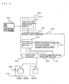
- Fig. 1 is a block diagram showing a whole arrangement of a management system of facility equipment according to a first embodiment.
- the management system includes a centralized management unit 100 of the facility equipment, an outdoor machine 200 of an air-conditioner as the facility equipment to be managed, an indoor machine 210 corresponding to the outdoor machine 200, an interface member 300, a connection intermediating device 400, a public communication line 500 and a monitoring terminal 600.
- the centralized management unit 100 includes an input-side interface 110, an output-side interface 120, a storage section 130, an arithmetic processing section 140, a selection circuit 150, a display section 160 and a manipulating section 170.
- the input-side interface 110 is a connection interface connected to the facility equipment to be managed by the centralized management unit 100 allowing management data to be obtained from the facility equipment.
- the output-side interface 120 is a connection interface for outputting the management data obtained from the facility equipment and for receiving information transmitted from the monitoring terminal 600.
- Both of the input-side interface 110 and the output-side interface 120 are composed of data transmitting circuits.
- the storage section 130 stores a control program, a first transmission program and a second transmission program as well as information of usability for each program.
- At least one of the individual programs is stored in the storage section 130. Operation of each program will be described later. That all of them are usable is assumed to be set in the information of usability, in the first embodiment.
- the arithmetic processing section 140 is composed of a CPU and other components and carries out control of the facility equipment to be managed and processing of data transmission.
- the selection circuit 150 has a function of selecting which one of programs stored in the storage section 130 is to be used.
- the display section 160 displays operating states of the centralized management unit 100 and the facility equipment to the user of the centralized management unit 100.
- the manipulating section 170 is used by the user of the centralized management unit 100 to manipulate setting management conditions and others of the facility equipment.
- the centralized management unit 100 manages the operating states of the outdoor machine 200 and the indoor machine 210 of the air-conditioner.
- the outdoor machine 200 of the air-conditioner is connected to the input-side interface 110 and is installed at a suitable place within a complex facility not shown.
- Fig. 1 shows an example in which two outdoor machines 200 are connected to the input-side interface 110.
- the indoor machine 210 is installed so as to correspond to each indoor machine 200.
- one indoor machine 210 is connected to one outdoor machine 200 and two indoor machines 210 are connected to the other outdoor machine 200.
- the interface member 300 includes a transmission mode reversibly converting circuit 310.
- One end of the interface member 300 is connected to the output-side interface 120 and the other end is connected to the connection intermediating device 400.
- the transmission mode reversibly converting circuit 310 reversibly converts the transmission modes of electrical signals at the input and output ends.
- the transmission mode reversibly converting circuit 310 converts data output from the output-side interface 120 into data what uses a transmission mode corresponding to an interface included in the connection intermediating device 400, and outputs the data. Similarly to that, the transmission mode reversibly converting circuit 310 converts data output from the interface included in the connection intermediating device 400 into data what uses the transmission mode corresponding to the output-side interface 120, and outputs the data.
- a measure for reinforcing and insulating the interface member 300 is taken through a known method when no such measure is taken for the outdoor machine 200 and the indoor machine 210.
- connection intermediating device 400 is a commercially available digital data transmitting device constructed by using a microprocessor for example and is one type of generally used IT devices.
- the connection intermediating device 400 includes a modem 410 and a data transmission circuit 420.
- the data transmission circuit 420 is connected to one end of the interface member 300 and is also connected to the connection intermediating device 400.
- the modem 410 exchanges data with the data transmission circuit and is also connected to the public communication line 500 to transmit/receive data via the public communication line 500.
- the centralized management unit 100 is connected to the public communication line 500 via the interface member 300 and the connection intermediating device 400 and is capable of transmitting/receiving data via the public communication line 500.
- the monitoring terminal 600 is provided within a management center not shown constructed at a remote place adequately separated from a place where each of the centralized management units 100 are installed and is adapted to be able to bilaterally communicate with the centralized management unit 100 via the connection intermediating device 400.
- the monitoring terminal 600 is capable of exchanging information with the air-conditioner to be managed by each of the centralized management units 100 or with facility equipment similar to that.
- the monitoring terminal 600 may be composed of a computer such as a personal computer.
- the user manipulates an input manipulation button not shown in the manipulating section 170 to set operating conditions of the air-conditioner.
- Data including these operating conditions set and inputted is displayed on the display section 160 and is transferred to the arithmetic processing section 140.
- the arithmetic processing section 140 exchanges information with the outdoor machine 200 and the indoor machine 210 via the input-side interface 110.
- Operations of the outdoor machine 200 and the indoor machine 210 are controlled in accordance with the data received via the input-side interface 110.
- the arithmetic processing section 140 receives data (management data) indicating operating conditions sampled by sensors not shown via the input-side interface 110 in accordance with an instruction of the first transmission program.
- the arithmetic processing section 140 displays the operating conditions of the air-conditioner on the display section 160, on the basis of the management data thus obtained.
- the arithmetic processing section 140 also controls the air-conditioner to be managed in accordance with instructions of a control program read out of the storage section 130 based on the data of operating conditions set and inputted as described above and the management data thus obtained.
- the arithmetic processing section 140 reads a second transmission program stored in an address set to be usable among information of usability stored in the storage section 130 and outputs a data (management data) signal indicating the operating states of the air-conditioner to be managed out of the output-side interface 120 in accordance with an instruction of the second transmission program.
- the interface member 300 reversibly converts the operating state data (management data) signal outputted from the output-side interface 120 so as to adjust to the transmission mode of the data transmission circuit 420. Thereby, the interfaces match in terms of electrical signal between the output-side interface 120 and the data transmission circuit 420 and information may be exchanged.
- the connection intermediating device 400 Upon receiving the operating state data (management data) from the data transmission circuit 420, the connection intermediating device 400 converts the operating state data signal received from the modem 410 to transmit the operating state data to the monitoring terminal 600 via the public communication line 500.
- the connection intermediating device 400 is provided with a USB connecting port to allow bilateral communications with the public communication line 500 by inserting a USB terminal attached to the modem 410 into the USB connecting port.
- USB Universal Serial Bus
- the first embodiment it becomes possible to accommodate to the various transmission modes by preparatively storing the second transmission program that accommodates to the transmission mode of the connection intermediating device 400 and by connecting the interface member 300 that corresponds to the transmission mode selected by the selection circuit 150 to an output terminal of the centralized management unit 100.
- connection intermediating device 400 used by the user simply and at low cost by storing only the transmission program corresponding to a transmission mode required by the user in the storage section 130 and by connecting the interface member 300 corresponding to the selected transmission program to the output terminal of the centralized management unit 100.
- connection intermediating device 400 changes in the future, it becomes possible to accommodate to the change simply and at low cost by changing the second transmission program stored in the storage section 130 and the interface member 300 corresponding to the changed transmission mode.
- the centralized management unit 100 may be used effectively for a long period of time without changing the design of the basic functions by allowing the members provided around the interface and the programs to be changed.
- connection intermediating device 400 fails and its transmission mode is non-operative, it becomes possible to compensate for this by changing the second transmission mode stored in the storage section 130 and the interface member 300 corresponding to a transmission mode of a presently commercially available connection intermediating device and it is not necessary to replace the centralized management unit 100 with a new one.
- connection intermediating device 400 it becomes possible to freely select places where the centralized management unit 100 and the connection intermediating device 400 are installed by adjusting a length of a cable connecting the output-side interface 120 with the interface member 300 or of a cable connecting the interface member 300 with the connection intermediating device 400.
- Fig. 2 is a block diagram showing a partial arrangement of the management system of the facility equipment according to a second embodiment.
- a management system of the facility equipment of the second embodiment is different from the first embodiment described above in that the selection circuit 150 is omitted, the arrangement of data stored in the storage section 130 is changed and a program setting device 700 is made connectable anew.
- the arrangement other than those is the same with the first embodiment.
- the storage section 130 has a storage area in which the first transmission program and the control program are stored in advance and a rewritable program writing area.
- the program writing area is provided on the assumption that a second transmission program corresponding to a transmission mode used by the data transmission circuit 420 of the connection intermediating device to be used from now on is stored in the area.
- program setting device 700 is made connectable to one end of the interface member 300 according to the second embodiment.
- the program setting device 700 writes and sets the second transmission program corresponding to the transmission mode used by the data transmission circuit 420 of the connection intermediating device 400 to be used from now on into the program writing area of the storage section 130.
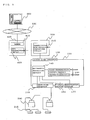
- Fig. 3 shows an arrangement at the time after the second transmission program has been written into the program writing area of the storage section 130 by the program setting device 700.
- Fig. 3 The arrangement shown in Fig. 3 is the same with the first embodiment shown in Fig. 1 except that the information of usability stored in the storage section 130 is omitted and the selection circuit 150 is omitted, so that their explanation will be omitted here.
- the program setting device 700 is connected to one end of the interface member 300 where the output-side interface 120 is not connected.
- the program setting device 700 outputs the second transmission program via the interface member 300.
- the arithmetic processing section 140 receives the second transmission program outputted from the program setting device 700 via the output-side interface 120 in accordance with the instruction of the first transmission program.
- the arithmetic processing section 140 writes the received second transmission program to the program writing area in the storage section 130.
- the program setting device 700 is disconnected from the interface member 300 and the connection intermediating device 400 is connected instead.
- connection intermediating device 400 is connected to the public communication line 500 via the modem 410 and is connected to the monitoring terminal 600 via the public communication line 500.
- a connection interface included in the program setting device 700 uses a transmission mode capable of transmitting data by the first transmission program.
- the second embodiment it becomes possible to accommodate to the interface (and the data transmission circuit 420) provided in the connection intermediating device 400 of the future that cannot be imagined in advance without changing any of the structure of the centralized management unit 100.
- connection intermediating device 400 even if the connection intermediating device 400 is replaced in the future, it becomes possible to accommodate to that simply and quickly without changing the structure of the centralized management unit 100.
- a storage capacity of the storage section 130 may be effectively reduced because the storage section 130 is adapted so that only the second transmission program currently required is written and set by the program setting device 700.
- the information of usability may be stored in the storage section 130 in the same manner with the first embodiment so that only a program set so as to be usable is executed.
- Fig. 4 is a block diagram showing a whole arrangement of the management system of the facility equipment according to a third embodiment.
- the management system of the facility equipment of the third embodiment is different from the first embodiment in that the path switching means 180 is provided on the output side of the output-side interface 120 to branch output destinations of the output-side interface 120.
- the output side of the centralized management unit 100 is branched by the path switching means 180 connected to the output-side interface 120.
- An interface member 300a is connected to one branch and an interface member 300b is connected to the other branch.
- the interface member 300a is connected with the connection intermediating device 400 in the same manner with the first embodiment.
- the interface member 300b is always connected with the program setting device 700.
- Fig. 5 shows an exemplary arrangement of the path switching means 180.
- the path switching means 180 is composed of a socket 180b and a switching contact member 180a, attached to a control panel of the centralized management unit 100.
- a connector 320b provided at one end of the interface member 300b can be inserted into the socket 180b.
- the program setting device 700 may be removably connected to the centralized management unit 100 without detaching the centralized management unit 100 fixed on the wall face.
- Fig. 6 is a block diagram showing a whole arrangement of the management system of the facility equipment according to a fourth embodiment.
- the management system of the facility equipment of the fourth embodiment is different from the third embodiment described above in that a path selection recognizing circuit 190 is provided.
- the path selection recognizing circuit 190 recognizes which data transmission path of the branch paths is selected by the path switching means 180.
- the arithmetic processing section 140 carries out the following processes corresponding to the recognition state of the path selection recognizing circuit 190.
- the arithmetic processing section 140 exchanges information with the program setting device 700 in accordance with the instruction of the first transmission program.
- the arithmetic processing section 140 exchanges information with the connection intermediating device 400 in accordance with the instruction of the second transmission program.
- path selection recognizing circuit 190 may be arranged also as follows:
- connection intermediating device 400 As described above, according to the fourth embodiment, because the information exchange is enabled between the program setting device 700 and the connection intermediating device 400 each having a different data transmission path, it becomes possible to apply the connection intermediating device 400 provided with an arbitrary data transmission circuit simply and quickly by always fixing the program setting device 700 and the interface member 300, which are otherwise carried by a serviceman, without repeating attachment/detachment thereof.
- the problem of unnoticed use described above may occur when an installer of the centralized management unit 100 finds out the encrypted information for example.
- the method of setting the information of usability in shipping out of the factory increases managerially economical burden of the manufacturer of the centralized management unit 100 and causes a problem that the manufacturing cost of the whole management system of the facility equipment becomes expensive.
- the fifth embodiment of the invention discloses an arrangement that eliminates the above-mentioned problem and provides the facility equipment operation controlling and monitoring functions required by the user at an adequate cost.
- Fig. 7 shows a procedure related to setting of the information of usability.
- Fig. 7A shows a processing procedure in shipping the centralized management unit 100 out of the factory
- Fig. 7B shows program use permission numbers
- Fig. 7C shows a procedure in setting the use permission number of the second transmission program.
- an unique manufacturing number code is inputted to the centralized management unit 100 by the program setting device 700 connected with the centralized management unit 100 to be shipped via the interface member 300b in shipping the centralized management unit 100 out of the factory.
- the inputted manufacturing number code is stored in the storage section 130.
- Fig. 7B shows a rule of the program use permitting numbers.
- the arithmetic processing section 140 calculates in accordance with an arithmetic algorism represented by the manufacturing number code and function f in which a program number code is a variable.
- the program is determined to be usable only when the calculated value of function coincides with an uniquely set program password, and the information of usability for the program is set to the effect that it is usable.
- Fig. 7C shows a state in setting the use permission number of the second transmission program in installing the centralized management unit 100 at a user specified location where the facility equipment is to be installed.
- the installer of the facility equipment inputs a program password by the program setting device 700 connected via the interface member 300b in the same manner as shown in Fig. 7A .
- the manufacturer of the centralized management unit 100 or the facility equipment can steadily recover charges for using the control program and the second transmission program by charging for the provision of the program use permission number to the installer.
- arithmetic algorism of the program password is not limited to what has been explained in connection with Fig. 7B and any method may be used as long as the password is uniquely defined.
- the method of causing the installer and others of the facility equipment to input the password is not limited to the method carried out by the program setting device 700 explained in connection with Fig. 7C and may be a method in which the password is inputted directly by using the manipulating section 170 of the centralized management unit 100, for example.
- Fig. 8 is a block diagram showing a whole arrangement of the management system of the facility equipment according to a sixth embodiment.
- an interface of EIA standard RS485 is used instead of the EIA standard RS232C, as the output-side interface of the centralized management units 100a and 100b.
- a refrigerator 220 and a cooling showcase 230 are subjects to be managed similarly to the air-conditioner.
- the refrigerator 220 and the cooling showcase 230 are often manufactured by different makers and generally they adopt the EIA standard RS485 as their interface.
- the centralized management units 100a and 100b can exchange information with each of the air-conditioners, the refrigerator 220 and the cooling showcase 230 and to manage all thermal equipments in one and same store by using the EIA standard RS485 for the interfaces of the communications with the refrigerator 220 and the cooling showcase 230.
- the monitoring terminal 600 can manage a plurality of centralized management units (the centralized management units 100a and 100b in Fig. 8 ) via the public communication line 500 and an interface member 300a.
- a building monitoring apparatus 800 installed within a building can also manage a plurality of centralized management units (the centralized management units 100a and 100b in Fig. 8 ) via an interface member 300b.
- a building management system 900 can also manage a plurality of centralized management units (the centralized management units 100a and 100b in Fig. 8 ) via an interface member 300c.
- the centralized management unit can be compatible with the various transmission modes by replacing the second transmission program within the centralized management units 100a and 100b and the interface members 300a, 300b and 300c to those corresponding to the interface included in each equipment.
- the centralized management unit can transmit data to all monitoring terminals and the like by replacing the second transmission program and the interface members corresponding to the interface included in each monitoring terminal and the like, such as Modem GSM communications for the monitoring terminal 600, USB Ethernet (Registered Mark) communications for the building monitoring apparatus 800 and EIB (European Installation Bus) Mode Bus for the building management system 900.
- Modem GSM communications for the monitoring terminal 600
- USB Ethernet Registered Mark
- EIB European Installation Bus
- the transmission mode allowing three or more communication equipments to be connected is used and the centralized management units 100a and 100b are allowed to exchange information via the interface members 300a, 300b and 300c, so that the plurality of centralized management units (the centralized management units 100a and 100b in Fig. 8 ) can manage in total in association with the monitoring terminal 600, the building monitoring apparatus 800 and the building management system 900, respectively.
- Fig. 9 explains about the display section 160 included in the centralized management unit 100 of the management system of the facility equipment according to a seventh embodiment.
- the display section 160 is made by using a dot matrix liquid crystal display in which any character can be displayed and displays information from the monitoring terminal 600 obtained via the communication line.
- the whole information may be displayed on the display section 160 by a known display circuit (not shown) by means of feed forward scroll.
- the whole message can be displayed even if the display section 160 is small like that of a small centralized management unit installed in a small shop.
Landscapes
- Engineering & Computer Science (AREA)
- Combustion & Propulsion (AREA)
- General Engineering & Computer Science (AREA)
- Mechanical Engineering (AREA)
- Chemical & Material Sciences (AREA)
- Signal Processing (AREA)
- Fuzzy Systems (AREA)
- Mathematical Physics (AREA)
- Physics & Mathematics (AREA)
- Human Computer Interaction (AREA)
- Computer Networks & Wireless Communication (AREA)
- Selective Calling Equipment (AREA)
- Air Conditioning Control Device (AREA)
Claims (9)
- Unité de gestion centralisée (100) pour un équipement d'installation (200), laquelle est apte à être connectée à au moins un élément d'équipement d'installation (200) devant être géré, laquelle est apte à obtenir des données de gestion en provenance dudit au moins un élément d'équipement d'installation (200), laquelle est apte à être connectée à un dispositif servant d'intermédiaire de connexion (400) pour connecter l'unité de gestion centralisée (100) à un terminal de surveillance (600), et laquelle est apte à transmettre les données de gestion au terminal de surveillance (600) par le biais du dispositif servant d'intermédiaire de connexion (400), et laquelle comporte :une interface côté entrée (110) apte à être connectée audit équipement d'installation (200) devant être géré ;une interface côté sortie (120) destinée à générer en sortie lesdites données de gestion dudit équipement d'installation (200) et à recevoir des informations transmises à partir dudit terminal de surveillance (600) ;une section de stockage (130) destinée à stocker un programme de commande dudit équipement d'installation (200) ; etune section de traitement arithmétique (140) destinée à commander ledit équipement d'installation (200) en fonction d'une instruction dudit programme de commande ;dans laquelle ladite section de stockage (130) stocke un premier programme de transmission correspondant à ladite interface côté entrée (110) et un second programme de transmission correspondant à une interface dudit dispositif servant d'intermédiaire de connexion (400) ;dans laquelle ladite section de traitement arithmétique (140) est apte à obtenir lesdites données de gestion à partir dudit équipement d'installation (200) par l'intermédiaire de ladite interface côté entrée (110) selon une instruction dudit premier programme de transmission, et à générer en sortie lesdites données de gestion vers ladite interface côté sortie (120) dans un mode correspondant à l'interface dudit dispositif servant d'intermédiaire de connexion (400) selon l'instruction dudit second programme de transmission ;dans laquelle ladite section de traitement arithmétique (140) est apte à stocker un programme dans une zone destinée à stocker ledit second programme de transmission, sur la base d'informations reçues à partir de ladite interface côté sortie (120) sur ledit programme à stocker dans ladite zone où ledit second programme de transmission est stocké ;dans laquelle ladite unité de gestion centralisée (100) comprend en outre un moyen de commutation de chemin (180) pour dériver des destinations de sortie de ladite interface côté sortie (120), ledit moyen de commutation de chemin (180) étant apte à générer en sortie lesdites données de gestion dudit équipement d'installation (200) à partir d'un chemin de dérivation ; etdans laquelle un dispositif de définition de programme (700), destiné à définir des informations connexes à un programme devant être stocké dans la zone où ledit second programme de transmission est stocké, est connecté à l'autre chemin de dérivation.
- Unité de gestion centralisée (100) de l'équipement d'installation (200) selon la revendication 1, comprenant en outre un élément d'interface (300, 300a, 300b) destiné à convertir de façon réversible un signal électrique correspondant à ladite interface côté sortie (120) en un signal électrique correspondant à ladite interface dudit dispositif servant d'intermédiaire de connexion (400) ; dans laquelle ledit élément d'interface (300, 300a, 300b) est connecté à ladite interface côté sortie (120).
- Unité de gestion centralisée (100) de l'équipement d'installation (200) selon l'une quelconque des revendications 1 à 2, dans laquelle ledit second programme de transmission est apte à utiliser un mode de transmission par lequel des informations peuvent être échangées avec chaque dispositif parmi trois dispositifs connectés ou plus.
- Unité de gestion centralisée (100) de l'équipement d'installation selon l'une quelconque des revendications 1 à 3, dans laquelle
ledit moyen de commutation de chemin (180) est composé d'un support (180b) et d'un élément de contact de commutateur (180a). - Unité de gestion centralisée (100) de l'équipement d'installation selon l'une quelconque des revendications 1 à 4, comprenant en outre un moyen de reconnaissance de sélection de chemin (190) pour reconnaître à quel chemin de dérivation dudit moyen de commutation de chemin (180) l'équipement est connecté ; dans laquelle
ladite section de traitement arithmétique (140) reçoit ledit second programme de transmission par l'intermédiaire de ladite interface côté sortie (120) selon l'instruction dudit premier programme de transmission lorsque ledit moyen de reconnaissance de sélection de chemin (190) reconnaît une connexion audit dispositif de définition de programme (700), et elle génère en sortie lesdites données de gestion vers ladite interface côté sortie (120) selon l'instruction dudit second programme de transmission lorsque ledit moyen de reconnaissance de sélection de chemin (190) reconnaît une connexion audit dispositif servant d'intermédiaire de connexion (400). - Unité de gestion centralisée (100) de l'équipement d'installation selon l'une quelconque des revendications 1 à 5, dans laquelle
ladite section de stockage (130) maintient des informations indiquant si chaque programme est utilisable ou non, lesquelles définissent si chaque programme est utilisable ou non ; et
ladite section de traitement arithmétique (140) exécute un programme défini comme étant utilisable par lesdites informations indiquant si chaque programme est utilisable ou non, parmi des programmes respectifs stockés dans ladite section de stockage (130). - Unité de gestion centralisée (100) de l'équipement d'installation selon la revendication 6, comprenant en outre un moyen de saisie (700) pour saisir un mot de passe destiné à modifier lesdites informations indiquant si chaque programme est utilisable ou non, de sorte que lesdites informations indiquent que ledit programme est utilisable ; dans laquelle
ladite section de traitement arithmétique (140) modifie une partie corrélée avec ledit mot de passe en vertu d'une relation prédéterminée parmi lesdites informations indiquant si chaque programme est utilisable ou non, en recevant ledit mot de passe saisi par ledit moyen de saisie (700). - Unité de gestion centralisée (100) de l'équipement d'installation selon l'une quelconque des revendications 1 à 7, comprenant en outre une section d'affichage (160) destinée à afficher des informations transmises à partir dudit terminal de surveillance (600).
- Système de gestion d'équipement d'installation, comprenant :l'unité de gestion centralisée (100) de l'équipement d'installation selon l'une quelconque des revendications 1 à 8 ;un dispositif servant d'intermédiaire de connexion (400) destiné à connecter ladite unité de gestion centralisée (100) à un réseau ; etun terminal de surveillance (600) destiné à échanger des données avec ladite unité de gestion centralisée (100) par l'intermédiaire dudit réseau.
Applications Claiming Priority (2)
| Application Number | Priority Date | Filing Date | Title |
|---|---|---|---|
| JP2006090970 | 2006-03-29 | ||
| PCT/JP2006/323234 WO2007110996A1 (fr) | 2006-03-29 | 2006-11-21 | appareil de gestion centralisée pour un équipement d'installation et système de commande |
Publications (4)
| Publication Number | Publication Date |
|---|---|
| EP2000746A2 EP2000746A2 (fr) | 2008-12-10 |
| EP2000746A9 EP2000746A9 (fr) | 2009-03-04 |
| EP2000746A4 EP2000746A4 (fr) | 2011-03-16 |
| EP2000746B1 true EP2000746B1 (fr) | 2015-09-09 |
Family
ID=38540931
Family Applications (1)
| Application Number | Title | Priority Date | Filing Date |
|---|---|---|---|
| EP06833080.2A Not-in-force EP2000746B1 (fr) | 2006-03-29 | 2006-11-21 | Appareil de gestion centralisée pour un equipement d'installation et système de commande |
Country Status (5)
| Country | Link |
|---|---|
| US (1) | US7610116B2 (fr) |
| EP (1) | EP2000746B1 (fr) |
| JP (1) | JP4753951B2 (fr) |
| CN (1) | CN100585289C (fr) |
| WO (1) | WO2007110996A1 (fr) |
Families Citing this family (7)
| Publication number | Priority date | Publication date | Assignee | Title |
|---|---|---|---|---|
| KR20100123486A (ko) * | 2009-05-15 | 2010-11-24 | 엘지전자 주식회사 | 공기조화기 및 그 제어방법 |
| JP5808922B2 (ja) * | 2011-03-16 | 2015-11-10 | 三菱電機株式会社 | 空調機制御インターフェース装置、空気調和機および空調機制御システム |
| JP5822583B2 (ja) * | 2011-07-26 | 2015-11-24 | 三菱電機エンジニアリング株式会社 | 空調機器管理システム |
| US9546797B2 (en) * | 2011-07-27 | 2017-01-17 | Mitsubishi Electric Corporation | Air conditioner management device, air conditioner management system, non-transitory computer-readable recording medium and air conditioner management method |
| EP2760218B1 (fr) * | 2011-09-22 | 2018-03-07 | Mitsubishi Electric Corporation | Système de surveillance à distance, dispositif de collecte de données et dispositif de surveillance |
| JP5986511B2 (ja) * | 2013-01-25 | 2016-09-06 | アズビル株式会社 | 表示装置 |
| JP2018044735A (ja) * | 2016-09-15 | 2018-03-22 | ダイキン工業株式会社 | 空調装置又は冷凍装置 |
Family Cites Families (19)
| Publication number | Priority date | Publication date | Assignee | Title |
|---|---|---|---|---|
| US4418333A (en) * | 1981-06-08 | 1983-11-29 | Pittway Corporation | Appliance control system |
| JPH04189052A (ja) * | 1990-11-22 | 1992-07-07 | Nissin Electric Co Ltd | Crt装置のオンライン監視制御ソフトウェア |
| JP3257015B2 (ja) | 1992-02-25 | 2002-02-18 | 松下電工株式会社 | 位置認識機能を有するネットワーク |
| JP2799809B2 (ja) * | 1993-02-16 | 1998-09-21 | 株式会社日立製作所 | 空調管理システム |
| JPH1091421A (ja) | 1996-09-13 | 1998-04-10 | Toshiba Corp | 伝送ソフトウエア生成支援装置 |
| US6192282B1 (en) * | 1996-10-01 | 2001-02-20 | Intelihome, Inc. | Method and apparatus for improved building automation |
| JPH11281132A (ja) * | 1998-03-30 | 1999-10-15 | Mitsubishi Electric Corp | 空調管理システム |
| JP2000266390A (ja) | 1999-03-18 | 2000-09-29 | Mitsubishi Electric Corp | 空調機の遠隔制御システム |
| US6662077B2 (en) * | 1999-07-30 | 2003-12-09 | Gerhard Haag | Architecture for presenting and managing information in an automated parking and storage facility |
| WO2002010652A1 (fr) * | 2000-07-28 | 2002-02-07 | Kitz Corporation | Systeme de commande a fonction de communication et systeme de commande d'installation |
| JP3864285B2 (ja) | 2000-09-06 | 2006-12-27 | 株式会社日立製作所 | 空気調和機の管理システム及びそれに用いられる変換装置 |
| JP3622657B2 (ja) * | 2000-09-18 | 2005-02-23 | 株式会社日立製作所 | 空調制御システム |
| JP3822475B2 (ja) * | 2001-09-14 | 2006-09-20 | 三菱電機株式会社 | 電力系統管理方法及び電力系統管理システム |
| US6978627B2 (en) * | 2002-01-31 | 2005-12-27 | Mitsubishi Denki Kabushiki Kaisha | Air conditioner control system, central remote controller, and facility controller |
| JP4106941B2 (ja) | 2002-03-25 | 2008-06-25 | 三菱電機株式会社 | 空気調和装置の制御システム、遠隔集中管理装置、並びに制御システムの制御方法 |
| DE60311400T2 (de) * | 2002-12-10 | 2007-11-29 | Lg Electronics Inc. | Mehrzonenklimaanlage mit integriertem Steuersystem |
| JP4229081B2 (ja) | 2004-05-19 | 2009-02-25 | 住友電気工業株式会社 | 伝送方式変換装置 |
| KR100722271B1 (ko) * | 2005-03-15 | 2007-05-28 | 엘지전자 주식회사 | 빌딩관리시스템 |
| JP2006079632A (ja) | 2005-09-29 | 2006-03-23 | Fujitsu Ltd | 情報機器システム |
-
2006
- 2006-11-21 US US11/919,059 patent/US7610116B2/en not_active Expired - Fee Related
- 2006-11-21 JP JP2007548256A patent/JP4753951B2/ja not_active Expired - Fee Related
- 2006-11-21 WO PCT/JP2006/323234 patent/WO2007110996A1/fr not_active Ceased
- 2006-11-21 CN CN200680018678A patent/CN100585289C/zh not_active Expired - Fee Related
- 2006-11-21 EP EP06833080.2A patent/EP2000746B1/fr not_active Not-in-force
Also Published As
| Publication number | Publication date |
|---|---|
| EP2000746A4 (fr) | 2011-03-16 |
| WO2007110996A1 (fr) | 2007-10-04 |
| US20080154397A1 (en) | 2008-06-26 |
| JP4753951B2 (ja) | 2011-08-24 |
| EP2000746A9 (fr) | 2009-03-04 |
| JPWO2007110996A1 (ja) | 2009-08-06 |
| EP2000746A2 (fr) | 2008-12-10 |
| CN100585289C (zh) | 2010-01-27 |
| US7610116B2 (en) | 2009-10-27 |
| CN101184958A (zh) | 2008-05-21 |
Similar Documents
| Publication | Publication Date | Title |
|---|---|---|
| EP1598714B1 (fr) | Appareil et méthode pour commander à distance des appareils ménagers | |
| US7712095B2 (en) | Remote control server, center server, and system constituted them | |
| US7295099B2 (en) | Home appliance network system and method for operating the same | |
| EP1666805A1 (fr) | Dispositif pour tester un contitionneur d'air | |
| EP3062178B1 (fr) | Dispositif sans fil, système de communication sans fil, module sans fil, module d'interface et procédé de communication | |
| EP2000746B1 (fr) | Appareil de gestion centralisée pour un equipement d'installation et système de commande | |
| KR100949814B1 (ko) | 무정전전원장치의 통합 원격 감시 시스템 | |
| EP1657639A1 (fr) | Système et procédé de mise à niveau logicielle d'une unité extérieure | |
| KR101968945B1 (ko) | 휴대용 공조기기 도킹 스테이션 및 그를 포함하는 공조기기 유지관리 시스템 | |
| KR100479171B1 (ko) | 유무선 겸용 단말기를 사용한 원격제어감시시스템 | |
| JP4162236B2 (ja) | 熱源機通信システム | |
| KR20030027975A (ko) | 원격검침용 무선모뎀 | |
| KR20030012909A (ko) | 이동통신 단말기와 그 충전기를 통한 홈 네트워크 시스템및 제어방법 | |
| JP4613681B2 (ja) | リモート入出力装置、分散独立型リモートシステム及び無線伝送システム | |
| US6456893B1 (en) | Apparatus management system | |
| JP2002287819A (ja) | 移動・携帯型データ収集システム、データ収集方法及びデータ監視システム | |
| JP4423737B2 (ja) | 電力・電灯線通信システム | |
| KR100745579B1 (ko) | 모듈형 공기조화기의 통신 장치 및 방법 | |
| KR100757945B1 (ko) | 시스템 에어컨의 통신에러 운전장치 및 그 방법 | |
| KR100469497B1 (ko) | 원격검침을 사용한 멀티 에어컨 검침 시스템 | |
| JP4846386B2 (ja) | 通信システム | |
| KR20060059034A (ko) | 공기 조화기의 상태를 모니터링하는 장치 | |
| JP2006140569A (ja) | 情報システム、制御方法、およびそのプログラム | |
| HK1010922A1 (en) | Apparatus management system | |
| HK1010922B (en) | Apparatus management system |
Legal Events
| Date | Code | Title | Description |
|---|---|---|---|
| PUAI | Public reference made under article 153(3) epc to a published international application that has entered the european phase |
Free format text: ORIGINAL CODE: 0009012 |
|
| 17P | Request for examination filed |
Effective date: 20071204 |
|
| AK | Designated contracting states |
Kind code of ref document: A2 Designated state(s): DE ES FR GB IT |
|
| PUAB | Information related to the publication of an a document modified or deleted |
Free format text: ORIGINAL CODE: 0009199EPPU |
|
| DAX | Request for extension of the european patent (deleted) | ||
| RBV | Designated contracting states (corrected) |
Designated state(s): DE ES FR GB IT |
|
| A4 | Supplementary search report drawn up and despatched |
Effective date: 20110215 |
|
| RIC1 | Information provided on ipc code assigned before grant |
Ipc: F24F 11/02 20060101AFI20071106BHEP Ipc: G06F 13/00 20060101ALI20110209BHEP |
|
| RIC1 | Information provided on ipc code assigned before grant |
Ipc: F24F 11/02 20060101AFI20150212BHEP Ipc: G06F 13/00 20060101ALI20150212BHEP Ipc: F24F 11/00 20060101ALI20150212BHEP |
|
| GRAP | Despatch of communication of intention to grant a patent |
Free format text: ORIGINAL CODE: EPIDOSNIGR1 |
|
| INTG | Intention to grant announced |
Effective date: 20150427 |
|
| RIN1 | Information on inventor provided before grant (corrected) |
Inventor name: MASUI, HIROTAKA |
|
| GRAS | Grant fee paid |
Free format text: ORIGINAL CODE: EPIDOSNIGR3 |
|
| GRAA | (expected) grant |
Free format text: ORIGINAL CODE: 0009210 |
|
| AK | Designated contracting states |
Kind code of ref document: B1 Designated state(s): DE ES FR GB IT |
|
| REG | Reference to a national code |
Ref country code: GB Ref legal event code: FG4D |
|
| REG | Reference to a national code |
Ref country code: DE Ref legal event code: R096 Ref document number: 602006046621 Country of ref document: DE |
|
| PG25 | Lapsed in a contracting state [announced via postgrant information from national office to epo] |
Ref country code: ES Free format text: LAPSE BECAUSE OF FAILURE TO SUBMIT A TRANSLATION OF THE DESCRIPTION OR TO PAY THE FEE WITHIN THE PRESCRIBED TIME-LIMIT Effective date: 20150909 |
|
| PG25 | Lapsed in a contracting state [announced via postgrant information from national office to epo] |
Ref country code: IT Free format text: LAPSE BECAUSE OF FAILURE TO SUBMIT A TRANSLATION OF THE DESCRIPTION OR TO PAY THE FEE WITHIN THE PRESCRIBED TIME-LIMIT Effective date: 20150909 |
|
| REG | Reference to a national code |
Ref country code: DE Ref legal event code: R097 Ref document number: 602006046621 Country of ref document: DE |
|
| PLBE | No opposition filed within time limit |
Free format text: ORIGINAL CODE: 0009261 |
|
| STAA | Information on the status of an ep patent application or granted ep patent |
Free format text: STATUS: NO OPPOSITION FILED WITHIN TIME LIMIT |
|
| 26N | No opposition filed |
Effective date: 20160610 |
|
| REG | Reference to a national code |
Ref country code: FR Ref legal event code: ST Effective date: 20160729 |
|
| PG25 | Lapsed in a contracting state [announced via postgrant information from national office to epo] |
Ref country code: FR Free format text: LAPSE BECAUSE OF NON-PAYMENT OF DUE FEES Effective date: 20151130 |
|
| REG | Reference to a national code |
Ref country code: DE Ref legal event code: R079 Ref document number: 602006046621 Country of ref document: DE Free format text: PREVIOUS MAIN CLASS: F24F0011020000 Ipc: F24F0011890000 |
|
| REG | Reference to a national code |
Ref country code: DE Ref legal event code: R084 Ref document number: 602006046621 Country of ref document: DE |
|
| PGFP | Annual fee paid to national office [announced via postgrant information from national office to epo] |
Ref country code: DE Payment date: 20171114 Year of fee payment: 12 |
|
| REG | Reference to a national code |
Ref country code: GB Ref legal event code: 746 Effective date: 20180206 |
|
| REG | Reference to a national code |
Ref country code: DE Ref legal event code: R119 Ref document number: 602006046621 Country of ref document: DE |
|
| PG25 | Lapsed in a contracting state [announced via postgrant information from national office to epo] |
Ref country code: DE Free format text: LAPSE BECAUSE OF NON-PAYMENT OF DUE FEES Effective date: 20190601 |
|
| PGFP | Annual fee paid to national office [announced via postgrant information from national office to epo] |
Ref country code: GB Payment date: 20201112 Year of fee payment: 15 |
|
| GBPC | Gb: european patent ceased through non-payment of renewal fee |
Effective date: 20211121 |
|
| PG25 | Lapsed in a contracting state [announced via postgrant information from national office to epo] |
Ref country code: GB Free format text: LAPSE BECAUSE OF NON-PAYMENT OF DUE FEES Effective date: 20211121 |