EP2000610B1 - Ensemble composé de panneaux en forme tabulaire doté d'un élément de verrouillage mobile - Google Patents
Ensemble composé de panneaux en forme tabulaire doté d'un élément de verrouillage mobile Download PDFInfo
- Publication number
- EP2000610B1 EP2000610B1 EP08010141A EP08010141A EP2000610B1 EP 2000610 B1 EP2000610 B1 EP 2000610B1 EP 08010141 A EP08010141 A EP 08010141A EP 08010141 A EP08010141 A EP 08010141A EP 2000610 B1 EP2000610 B1 EP 2000610B1
- Authority
- EP
- European Patent Office
- Prior art keywords
- edges
- panels
- locking
- groove
- panel
- Prior art date
- Legal status (The legal status is an assumption and is not a legal conclusion. Google has not performed a legal analysis and makes no representation as to the accuracy of the status listed.)
- Not-in-force
Links
Images


Classifications
-
- E—FIXED CONSTRUCTIONS
- E04—BUILDING
- E04F—FINISHING WORK ON BUILDINGS, e.g. STAIRS, FLOORS
- E04F15/00—Flooring
- E04F15/02—Flooring or floor layers composed of a number of similar elements
-
- E—FIXED CONSTRUCTIONS
- E04—BUILDING
- E04F—FINISHING WORK ON BUILDINGS, e.g. STAIRS, FLOORS
- E04F15/00—Flooring
- E04F15/02—Flooring or floor layers composed of a number of similar elements
- E04F15/04—Flooring or floor layers composed of a number of similar elements only of wood or with a top layer of wood, e.g. with wooden or metal connecting members
-
- E—FIXED CONSTRUCTIONS
- E04—BUILDING
- E04F—FINISHING WORK ON BUILDINGS, e.g. STAIRS, FLOORS
- E04F2201/00—Joining sheets or plates or panels
- E04F2201/01—Joining sheets, plates or panels with edges in abutting relationship
- E04F2201/0107—Joining sheets, plates or panels with edges in abutting relationship by moving the sheets, plates or panels substantially in their own plane, perpendicular to the abutting edges
- E04F2201/0115—Joining sheets, plates or panels with edges in abutting relationship by moving the sheets, plates or panels substantially in their own plane, perpendicular to the abutting edges with snap action of the edge connectors
-
- E—FIXED CONSTRUCTIONS
- E04—BUILDING
- E04F—FINISHING WORK ON BUILDINGS, e.g. STAIRS, FLOORS
- E04F2201/00—Joining sheets or plates or panels
- E04F2201/01—Joining sheets, plates or panels with edges in abutting relationship
- E04F2201/0138—Joining sheets, plates or panels with edges in abutting relationship by moving the sheets, plates or panels perpendicular to the main plane
-
- E—FIXED CONSTRUCTIONS
- E04—BUILDING
- E04F—FINISHING WORK ON BUILDINGS, e.g. STAIRS, FLOORS
- E04F2201/00—Joining sheets or plates or panels
- E04F2201/01—Joining sheets, plates or panels with edges in abutting relationship
- E04F2201/0153—Joining sheets, plates or panels with edges in abutting relationship by rotating the sheets, plates or panels around an axis which is parallel to the abutting edges, possibly combined with a sliding movement
-
- E—FIXED CONSTRUCTIONS
- E04—BUILDING
- E04F—FINISHING WORK ON BUILDINGS, e.g. STAIRS, FLOORS
- E04F2201/00—Joining sheets or plates or panels
- E04F2201/05—Separate connectors or inserts, e.g. pegs, pins, keys or strips
-
- E—FIXED CONSTRUCTIONS
- E04—BUILDING
- E04F—FINISHING WORK ON BUILDINGS, e.g. STAIRS, FLOORS
- E04F2201/00—Joining sheets or plates or panels
- E04F2201/05—Separate connectors or inserts, e.g. pegs, pins, keys or strips
- E04F2201/0523—Separate tongues; Interlocking keys, e.g. joining mouldings of circular, square or rectangular shape
- E04F2201/0541—Separate tongues; Interlocking keys, e.g. joining mouldings of circular, square or rectangular shape adapted to be moved along the joint edge
Definitions
- the invention relates to a set of tabular panels, each comprising a top, a bottom, two first opposite edges and two second opposite edges.
- Akzenta is a set of rectangular floor panels with two short opposite edges and two long opposite edges known.
- One edge each comprises a retaining profile in the form of a hook or roof tile profile, which extends along the respective edge and is designed such that it can be connected to a substantially complementary design retaining profile of the opposite edge.
- the retaining profiles have a V-shaped clip with a free resilient leg and a leg fixedly connected to the floor panel.
- the V-shaped clip or the free resilient leg of the V-clip can be considered as a movable locking element, which ensures a positive connection in the direction of D1 when it assumed a locking position has, namely a position in which the resilient V-leg is in the locking groove.
- a locking position in which the V-leg is pressed to the fixed leg, however, as already stated above, the joining of the holding profiles along the direction D1 is possible.
- the direction D1 extends vertically to a laying plane in which the floor panels lie in the laid state.
- first panel and a second panel of the EP 1 415 056 B1 These panels are on the short edges - in addition to the positive connection by means of the V-clip in the direction D1 - due to the hook-shaped holding profiles in a direction D2 perpendicular to the direction D1 positively connected to each other.
- the first and second panels form part of a row X of panels, with which a third panel can be joined along the long edges to form another row X + 1 of panels.
- a large-scale floor which consists of several juxtaposed rows of panels, each arranged in a row behind the other and connected at the short edges.
- the EP 1 415 056 B2 and the WO 2006/043893 A1 thus disclose movable locking elements that result in automatic locking of retaining profiles when assembled together. For example, if two panels are locked at their short edges by the locking element, a release of the connection of the holding profiles of the short edges is difficult or impossible. This not only complicates the dismantling of a misplaced Floor, but also complicates the laying when panels of different decor or appearance are to be joined together to form a series of panels, but their aesthetic interaction should be tested by first trying only.
- the invention is therefore based on the object to provide a set of tabular panels that can be installed very easily.
- the set of tabular panels according to claim 1 is characterized in that in the mounting position, the locking element of the holding profiles of the first edges of the first and second panels with one end in the holding profile of the row X + 1 facing the second edge of the first and / or second Panels protrudes and that the locking element is pressed in connecting the third panel with the first and / or the second panel of the row X by the holding profile of the third panel in the locking position.
- the locking element protrudes with one end into the retaining profile of the row X + 1 facing the second edge.
- This protrude can only be a few millimeters, for example 1 to 7 mm.
- the path that the end of the locking element travels when it is pushed from the mounting position to the locking position, is preferably also only a few millimeters, for example 1 to 6 mm. In the locking position, the end can still protrude into the retaining profile, albeit to a lesser extent.
- these are rectangular panels, in particular around floor panels, wherein the first edges are shorter than the second edges.
- the locking element is provided at least at the short edges.
- the locking element is provided on at least one of the long edges.
- a respective locking element can be provided on the short edges and on the long edges.
- the panels may deviate from the rectangular shape and take, for example, a diamond-shaped form.
- the panels according to the invention can also have more than four edges, for example six or eight edges.
- the direction D1 in which in the mounting position of the locking element, the holding profiles can fit together and in which the locking element ensures in the locking position for a positive connection between the holding profiles, parallel to a laying plane E, in which laid the panels in the State lie.
- the first and second panels can be joined at their first edges by displacing the panels in the laying plane E. If the locking element is then pressed out of the mounting position into the locking position by the third panel, it is no longer possible to pull apart the retaining profiles of the first and second panels transversely to the connected short edges.
- the direction D1 runs perpendicular to the laying plane E.
- panels can be connected to each other at the first edges by lowering the second panel from above into the laying plane.
- This movement can be a linear movement, but also a pivoting movement.
- the locking element is arranged in a locking groove of one of the retaining profiles of the first edges, while a further locking groove is provided on the other retaining profile of the first edges.
- the corresponding locking grooves face each other and form a blocking channel.
- the locking element protrudes into the locking position in the further locking groove. This prevents the opposing blocking grooves from being laterally, i. transversely to the longitudinal extension of the grooves, which ensures the form fit in direction D1.
- the locking element may be integrally formed. It is also possible that the locking element consists of several individual components.
- the locking element could comprise a sliding cage which is clipped into the locking groove of one of the retaining profiles or otherwise secured in the locking groove.
- the sliding cage forms the receptacle of a single element, which is arranged movably in the sliding cage and is at least partially pushed out of the sliding cage in the locking position. Also, it does not necessarily have to be the component that protrudes into the retaining profile of the second edge, which ultimately ensures the locking of the retaining profiles at the first edge.
- the locking element is elastically deformed in the locking position.
- a restoring force is given, which forces the locking element from the locking position back into the mounting position when the panels are removed.
- the locking element can automatically return to the mounting position, unlocking the connection of the X series panels at the short edges.
- the locking element may extend substantially the entire length of the first edges. For example, if the first edges are 20 cm long, then the length of the locking element is also about 20 cm. It should be considered that the locking element must survive at one end of the short edge, while at the other end of the edge can be provided a support for the locking element. Also, the locking element in a selected embodiment, both at one and at the other end of the short edge protrude. A support of the locking element could be done by panels of an already laid row X-1.
- the locking element may comprise a strip of plastic or metal.
- the strip may have at least one buckle in the assembled position, which increases when the strip is pressed into the locking position.
- the curvature in the assembly position ensures that when compressing the strip a defined deformation of the same takes place.
- the strip may have a plurality of bulges which increase upon compression. In principle, other means may be provided which allow deformation of the locking element in only a desired manner.
- the retaining profiles at the first edges may comprise two hook profiles which can be connected by relative movement in a direction perpendicular to the laying plane. These hook profiles are thus suitable for the embodiment in which the direction D1 already described above is perpendicular to the laying plane E.
- the holding profiles at the first edges may have a groove and a spring, wherein the holding profiles can be connected by moving the panels in the laying plane. This corresponds to the embodiment already described above, in which the direction D1 runs parallel to the laying plane E.
- the retaining profile of the second edge of the third panel which faces the row X
- the retaining profiles of the second edge of the first and / or second panel already located in the laying plane by attaching at an angle to the laying plane and subsequent pivoting of the third panel the second edge can be connected in the laying plane. From this, a connection can be made between the panels of row X + 1 and the row X, which are transverse to the second edges both in one direction perpendicular to the laying plane and in a direction parallel to the laying plane is positively formed.
- the retaining profiles at the second edges may have a groove and a tongue, wherein the groove is bounded by a lower lip and an upper lip.
- a locking shoulder can be formed, which engages in a locking groove on an underside of the spring. The engagement of the locking shoulder in the locking groove ensures - together with opposing upper edges of the holding profiles - for a positive engagement parallel to laying plane when the spring has been inserted into the groove and the holding profiles are connected together.
- locking groove and locking shoulder and other means can be used in a tongue and groove connection, can be made parallel to the laying plane by a positive connection.
- the groove may be formed drop-shaped on its underside, wherein the lower lip is formed complementary to the spring-facing side.
- the spring can be introduced by a pivoting movement and / or by lateral sliding into the groove, wherein by the locking shoulder and the locking groove or by the other means preferably a noticeable engagement (Click) of the connection takes place.
- the retaining profiles on the second edges may be designed so that the locking shoulder and the locking groove or the other alternative means are under tension against each other, which voltage causes the upper edges of the retaining profiles are pressed together.
- a game between the retaining profiles may be provided parallel to the laying plane, so that no voltage is generated by the interaction between the locking shoulder and locking groove through which the upper edges are pressed together.
- neither a game nor a tension is parallel to the laying level between the holding profiles.
- the locking element In the assembled position, the locking element can protrude with the end in the groove of the holding profiles of the second edge, for example, 1 to 7 mm calculated from the groove bottom. It is located at least partially between the upper and lower lip.
- the spring When inserting the spring into the groove for connecting the retaining profiles to the second edges, the spring can press the end towards the groove bottom out of the groove, whereby the locking element then assumes the locking position.
- In the locking position is preferably the end of the locking element on the spring.
- the spring and / or the end of the locking element may have means by which the end passes through a maximum in the movement of the locking element from the mounting position to the locking position. This means that the end in an intermediate position is pressed out of the groove to a maximum extent to then move back in the locking position of the locking element, for example by the restoring force of the deformed in the locking position locking element. This allows a tactile locking of the locking element set. If the retaining profiles at the second edges by a click (Click) connected, thus creating a two-time snapping or "clicking", namely on the one hand by the engagement of the locking element and then, preferably with a short time delay, by the holding profiles themselves (double click).
- the retaining profiles on the second edges, locking element and provided on the first edges holding profiles are designed with the locking channel forming locking grooves so that when connecting the holding profiles at the second edge first, the first and second panels are aligned with each other in height, thereby it is ensured that the locking channels of the holding profiles at the first edges facing each other without offset. Only then should the locking element be pressed into the further locking groove. If, for example, the holding profiles at the second edges can be connected by oblique attachment of the third panel and subsequent pivoting down, an alignment can first be effected by the oblique attachment without the locking element being already moved. The alignment has the consequence that a possible height offset between the opposing spear grooves is reduced.
- the third panel is pivoted down, in which case the locking element is moved to the locking position.
- the locking element may have on one of the further locking groove facing sides insertion bevels, which facilitate insertion into the further locking groove.
- the retaining profiles on the second edges may be displaceable relative to one another along the edges. This opens up the possibility of displacing panels within a row X + 1 in order to establish a connection at the short edges, even though these panels in this row X + 1 are already connected to a neighboring row X.
- the force of the locking element can act parallel to the laying plane, so that the panels are pressed against each other at their tops, creating a gap-free Connection to be achieved. It is also possible that the locking element exerts a force perpendicular to the laying plane, whereby a possible height difference of the adjacent tops of connected panels should be avoided.
- the locking element is in a locking channel, which is formed by two opposing locking grooves, the locking element can exert a force by which the locking grooves are pressed apart and thus a gap between the retaining profile walls may arise, on which the locking grooves are arranged. As stated above, however, this can be used selectively to close possible other gaps between the holding profiles.
- a set of tabular panels each having two first opposite edges and two second opposite edges, one edge each comprising a retaining profile extending along an edge and formed in such a way that it is connectable to a substantially complementary formed retaining profile of the opposite edge, wherein the holding profiles of the first edges have a movable clamping element which exerts a force in a clamping position, whereby the holding profiles are pressed against each other to a possible gap and / or a possible Height difference between tops of the panels to minimize or minimize, wherein in the installed state, a first panel and a second panel are connected to each other at the first edge and form a row X of panels with which ver along the second edges ver a third panel can bind to form another row X + 1 of panels, wherein in an assembly position, the clamping element protrudes with one end in the holding profile of the row X + 1 facing the second edge of the first and / or the second panel, and wherein the third
- the kit according to claim 1 may comprise additional activating means by which the locking element of the retaining profiles of the first edges of panels of a last row can be pushed into the locking position. This ensures that even the panels of the last row are positively connected to one another at their first edges in the directions D1 and D2.
- the additional activating means may have a narrow strip which has a retaining profile on one longitudinal side, which can be connected to the retaining profile of the panels of the last row at the second edge and thereby presses the locking element into the locking position.
- the strip which can also be described as the end strip, can be 10 to 25 mm wide.
- the activation means may comprise a wedge, which can be inserted laterally into the locking groove and thereby presses the locking element seated in the locking groove in its locking position.
- laying the last row can proceed so that first the panels of the last row are locked together at their first edges by means of the wedge and then this last row is applied at an angle to the laying plane E to the penultimate row and then into the Laying plane is pivoted, as has already been described above in a preferred embodiment.
- the use of the wedge is possible even if the panels of the last row have previously been cut to a smaller width due to limited space.
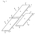
- FIG. 1 shows a perspective view of three laminate panels 1, 2, 3, which are designed identical.
- the panel 1 has an upper side 4 and a lower side 5.
- a circumferential edge of the panel 1 is composed of two first edges 6, 6 'and two second edges 7, 7' together. Due to the elongated shape of the panel 1, the first edges 6, 6 'are recognizably shorter than the second edges 7, 7'. In the following, therefore, the first edges are referred to as short edges 6, 6 'and the second edges as long edges 7, 7'. Due to the identical design, the panels 2, 3 are provided with the same reference numerals.
- the panels 1, 2, 3 are provided at the edges 6, 6 ', 7, 7' with retaining profiles, which in the FIG. 1 for the sake of simplicity are not shown. Preferred embodiments for holding profiles, the FIGS. 2 to 4 be removed.
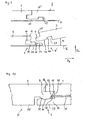
- FIG. 2 shows as a first embodiment holding profiles 8, 8 'at the short edges 6, 6' of the panels 1, 2 in cross section, wherein in an upper part of the FIG. 2 the holding profiles 8, 8 'connected together and in a lower part of the FIG. 2 are separated from each other.
- the retaining profile 8 has a spring 9, which can be inserted into a groove 10 of the retaining profile 8 '(see the upper part of FIG. 2 ).
- the groove 10 is bounded by a lower lip 11 and an upper lip 12.
- a locking groove 14 is incorporated in the lower lip 11, in which a locking element 15 is seated.
- the locking element 15 has substantially the shape of a slightly curved strip, which is made of an elastic material such as plastic or metal. The thickness and the curvature of the strip 15 are dimensioned such that it is completely absorbed by the locking groove 14 as far as the groove height is concerned.
- the groove 9 On a bottom 16, the groove 9 has a locking groove 17 which in the connected state of the holding profiles 8, 8 '(see the upper part of FIG. 2 ) forms a common barrier channel 18 which has a rectangular cross-section.
- the strip-shaped locking element 15 is bent in the locking channel so that it protrudes from the locking groove 14 beyond the lower groove side wall 13 also into the locking groove 17 and pulling the panels 1, 2 in the direction D1 (see arrow in FIG FIG. 2 ) prevented.
- the locking element 15 rests with certain areas on the groove side walls of the locking groove 14 and with other areas on the groove side walls of the locking groove 17. As the locking element 15 from the mounting position (see lower part of FIG. 2 ) enters the more curved locking position will be described in detail below.
- the locking element 15 in the locking position ensures a positive connection between the retaining profiles 8, 8 'in the direction D1.
- the direction D1 runs across the holding profiles 8, 8 'and parallel to an underbody U or to a laying plane E, in which the panels 1, 2 are in the laid state. Due to the interaction of spring 9 and groove 10, a form fit in a direction D2 is given at the same time, ie transversely to the holding profiles 8, 8 'and perpendicular to the underbody U.
- FIG. 3 Another embodiment of retaining profiles on the short edges 6, 6 'shows FIG. 3 ,
- the holding profiles shown there are provided with the reference numerals 19, 19 '.
- FIG. 2 shows FIG. 3 in an upper part of the figure, the holding profiles 19, 19 'in a connected state, while a lower part shows these holding profiles 19, 19' separated from each other.
- FIG. 3 becomes a component that becomes a component of FIG. 2 identical or similar, provided with a correspondingly the same reference numerals. This applies mutatis mutandis to all other figures, to which reference is made later.
- the holding profiles 19, 19 ' are formed as hook profiles which are characterized by a simple vertical movement of a panel 2 spaced from the subfloor U (see lower part of FIG. 3 ).
- the hook profile 19 On a hook inner wall 20, the hook profile 19 has a locking groove 14 in which a locking element 15 is seated. Again, in the representation of the lower part of the locking element 15 does not protrude from the locking groove 14 on the hook inner wall 20.
- the hook profile 19 ' has a locking groove 17, which in the assembled state of the holding profiles 19, 19' (see the upper part of FIG. 3 ) form a closed barrier channel 18.
- the curvature of the locking element 15 in the upper part of FIG. 3 is so large that the holding profiles 19, 10 'are locked in the direction D1.
- the direction D1 is that direction in which the retaining profiles can be inserted into each other, as far as the locking element 15 is in the assembled position, while it reliably prevents a pulling apart of the retaining profiles in exactly this direction in the locking position.
- the locking grooves 14, 17 can in the embodiment of FIG. 3 also be provided on another pair of vertically extending hook walls.
- the locking grooves 14, 17 may also be provided on the vertically extending hook walls 23, 24 or 25, 26. It is also arbitrary, in which of the locking grooves 14, 17, the locking element 15 is seated in the assembled position. The same applies mutatis mutandis to the embodiment of FIG. 2 with the proviso that here the locking grooves can be arranged on other pairs of horizontally extending groove or spring walls.
- FIG. 4 shows an embodiment of retaining profiles on the long edges 7, 7 'of the panels 1, 3.
- the holding profiles are designated by the reference numerals 27, 27'.
- the retaining profile 27 has a groove 10 which is bounded by a lower lip 11 and by an upper lip 12.
- a locking shoulder 28 is provided at the end, which in the locked state (see the upper part of FIG. 4 ) engages in a locking groove 29 of the retaining profile 27 '.
- With the holding profiles 27, 27 ' can be between the panels 1, 3 a positive connection in the direction D p parallel to the substrate U and a positive connection in the direction D v vertical to reach the subfloor U.
- the holding profile 27' is guided at an angle ⁇ with its spring 9 in the groove 10, to then perform a pivoting movement with the panel 3, through which the panel 3 comes parallel to the subfloor U to the plant, like the upper part of the FIG. 4 shows.
- the holding profiles 27, 27 ' are shown only schematically. But they should be formed by a suitable geometry such that the above-described oblique attachment and the subsequent pivoting for locking the retaining profiles 27, 27 '(see FIG. 4 ) leads.
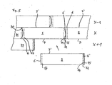
- FIG. 5 shows two panels 1, 2, which form part of a row X and at their opposite short edges 6 ', 6 via hook profiles according to the FIG. 3 connected to each other.
- the panels 1, 2 and thus the row X is connected via not shown here holding profiles on the long edges 7 'with panels of a row X-1.
- the retaining profile on the long edges 7 ' for example, the retaining profile 27' according to FIG. 4 correspond.
- the panel 1 on a likewise not shown holding profile, which could correspond to the holding profile 27.
- a strip-shaped locking element 15 (shown in phantom) is provided, which is housed in a slightly curved shape in a locking groove 14.
- the locking groove 14 is indicated only schematically by a dashed line.
- a locking groove 17 can be seen, in which a locking element 30 of another panel 31 of the row X protrudes. Compared to the locking element 15 of the panel 1, the locking element 30 is more curved. While the locking member 30 is in a locking position, thereby preventing the panel 1 from being lifted or pivoted upwardly relative to the panel 30, the locking member 15 is in an assembled position. In this mounting position, the hook profiles at the short edges 6, 6 'between the panels 1, 2 indeed hooked together, but it would be possible to raise the panel 2 relative to the panel 1. This lifting should be brought about by a pivoting movement of the panel 2 about its long edge 7 '.
- one end 32 of the locking element 15 projects beyond the long edge 7 of the panel 1. Strictly speaking, the end 32 protrudes into the holding profile, not shown here, on the long edge 7 of the panel.
- a panel 3 is applied to the long edges 7 of the panels 1, 2 in order to form a further row X + 1 of panels with a panel 33, the retaining profile engages on the long edge 7 'of the panel 3 in the retaining profile the long edge of the panel 1 and presses the end 32 in the direction of the row X-1, whereby the locking element 15 is more curved. It is transferred into the locking position, as this - due to the laid panel 33 - the locking element 30 of the panel 31 is already the case. Only then are the panels 1, 2 locked.
- the locking element 15 springs back into the mounting position, when the panel 3 is removed from the row X + 1 again. If the panel 33 is also dismantled, the panels 2, 1, 31 of the row X can be successively raised or swung up around their long edges 7 'without the panel lying on the left being bent or otherwise having to be moved.
- FIG. 6 shows a corner 34 of a panel 1, which results from the collision of a short edge 6 'and a long edge 7. Cuts through the panel 1 of the FIG. 6 show the FIGS. 7 and 8th , For example, shows FIG. 7 the section along the line VII-VII in the FIG. 6 ,
- the panel 1 is provided on the short edge 6 'with a holding profile 35', which, like the holding profile 19 'of FIG. 3 is designed as a hook profile.
- a holding profile 35' In a vertical hook wall 25, a locking groove 14 is provided with locking element 15 disposed therein.
- the holding profile 35 ' can be connected to a trained as a hook profile retaining profile 35.
- This holding profile 35 has on a vertical hook wall 26, a further locking groove 17 which, when the holding profiles are joined together, the locking groove 15 is exactly opposite.
- the panel 1 is at the long edge 7 with a holding profile 36 (see also FIG. 7 ), which has substantially the same structure as the retaining profile 27 of FIG. 4 having.
- a groove 10 of the retaining profile 37 is bounded by a lower lip 11 and an upper lip 12.
- this groove 10 can be a spring 9 of a complementarily shaped retaining profile 36 'introduce, in FIG. 7 also outlined. It can be clearly seen that the locking element 15 protrudes with one end 32 into the groove 10 of the retaining profile 36. Now, if the spring 9 of the retaining profile 36 'is guided in the groove 10, the spring 9 presses the end 32, in the illustration of FIG. 7 , to the right, whereby the locking element 15 is more curved and now - as far as the retaining profiles 35 ', 35 have been previously joined - engages with the locking groove 17 of the retaining profile 35th
- FIG. 9 shows schematically the interaction of holding profiles on a long edge 7 of a panel 1 with a locking element 15 on a short edge 6 'panel 1.
- the holding profiles on the long edge 7 are denoted by 27, 27', since they the holding profiles of FIG. 4 correspond.
- FIG. 9 shows in an upper part of the locking element 15 in the assembled position and in a lower part in the locked position. In the mounting position, the locking element 15 is in a locking groove 14. A free or open end 32 of the locking element 15 projects into a groove 10 of the retaining profile 27th
- a locking groove 17 is arranged above the locking groove 14, a locking groove 17 is arranged.
- the interaction of locking element 15 and the locking grooves 14, 17 is based on the embodiment of FIG. 2 to explain, because there is a similar or same constellation.
- the locking grooves 14, 17 are each assigned to different retaining profiles 6, 6 'which, when the locking element is in the locking position, can not be pulled apart. Transferred to FIG. 9 this means that in locking position (lower part of the FIG. 9 ) the locking grooves 14, 17 and thus the corresponding holding profiles in a direction D1, which is perpendicular to the plane of the FIG. 9 extends, are positively connected to each other. In this case, a spring 9 of the retaining profile 27 presses the free end 32 out of the groove 10.
- the locking element 15 is compressed in its length, since another end 37 of the locking element 15 is supported on a stop 38. If the retaining profile 27 'again separated from the retaining profile 27, the locking element 15 jumps back into the mounting position (see the upper part of FIG. 9 ) and thus releases the positive connection between the locking grooves 14, 17.
- FIG. 10 a further example of holding profiles on the second edges 7, 7 'of the panels 1, 3.
- the local holding profiles are marked 39, 39'.
- a spring 9 engages in a groove 10 which is bounded by a lower lip 11 and an upper lip 12.
- the spring 9 has a teardrop shape with a convex-shaped bottom 40, which rests on a complementary shaped top 41 of the lower lip 11.
- the holding profiles 39, 39 ' can be achieved by obliquely attaching the holding profile 39' to the holding profile 39 and then swing down connect until the panels 1, 3 lie in a plane.
- FIG. 10 to take a locking element 15 which projects into the groove 10 with one end 32. Apart from the locking element 15 are in FIG. 10 no components or features of the first holding profiles of the panel 1 drawn; it is only a schematic representation.
- the locking element 15 is to be in its locking position in which it is elastically deformed.
- One end 32 of the locking element 15 rests against an end face 42 of the spring 9. It can be seen that the end 32 lies in a rounded recess 43 of the end face 42.
- the bottom 40 of the spring 9 While in the embodiment of FIG. 10 the bottom 40 of the spring 9 is convex, the bottom 40 of the spring 9 in the embodiment of FIG. 4 not curved, but runs straight and - as far as the holding profiles 27, 27 'rest on it - parallel to the bottom U.
- the straight bottom 40 is followed at right angles to a likewise rectilinear groove side wall 48 of the locking groove 29 (see FIG. 4 ).
- the top 41 of the lower lip 11 and a locking wall 47 of the locking shoulder 28 are each rectilinear and mutually perpendicular.
- FIGS. 11 and 12 show a further embodiment of retaining profiles on the short edges 6, 6 '.
- FIG. 11 shown holding profiles are similar to those FIG. 3 and are designated by reference numerals 44, 44 '.
- the main difference lies in the selected position of the opposing locking grooves 1,4, 17.
- the locking grooves form a common locking channel 18, in which the locking element 15 is located.
- the locking grooves 14, 17 in FIG. 11 provided on vertically extending hook walls, which are denoted by 23 and 24, respectively.
- the locking element 15 is intended to fill the barrier channel in such a way that it abuts both a groove bottom 45 of the locking groove 14 and a groove bottom 46 of the locking groove 17.
- FIGS. 12a to 12c should clarify the interaction of the locking element 15 and the locking grooves 14, 17, wherein FIG. 12c represents the state of the locking element 15, the in FIG. 11 given is.
- the FIG. 12c shows the locking grooves 14, 17 from above, ie from the top 4 of the panels 1, 2.
- the locking element 15 is located at FIG. 12c in the locking position, wherein the ends of which rest against the groove bottom 45 of the locking groove 14 and a central region of the locking element 15 bears against the groove bottom 46 of the locking groove 17.
- the Verriegelungslement 15 is elastically deformed.
- FIG. 12a shows the locking element 15 in the mounting position, in which the locking element protrudes with the end designated 32 in the retaining profile of the second edge and is not yet in the locking groove 17.
- the locking element may have the additional function of making the connection between two panels at the top of the panels as gap-free as possible.
Claims (14)
- Ensemble de panneaux (1, 2, 3) en forme de plaque, en particulier de panneaux de plancher en forme de plaque, comprenant chacun deux premières tranches opposées (6, 6') et deux secondes tranches opposées (7, 7'),
une tranche (6, 7) comprenant respectivement un profil de maintien qui s'étend le long de ladite tranche (6, 7) et qui est réalisé de manière à ce qu'il puisse être relié à un profil de maintien de la tranche (6', 7') opposée, qui est réalisé pour l'essentiel de façon complémentaire,
lesdits profils de maintien des premières tranches (6, 6') présentant un élément mobile de verrouillage (15) qui, dans une position de verrouillage, procure un engagement positif dans une direction D1 transversale auxdites premières tranches (6, 6') et qui, dans une position de montage, permet l'assemblage des profils de maintien suivant cette direction D1, et,
en état posé, un premier panneau (1) et un second panneau (2) étant reliés entre eux à engagement positif sur les premières tranches (6, 6') suivant une direction D2 perpendiculaire à ladite direction D1 et formant une rangée X de panneaux auxquels peut être relié, le long des secondes tranches, un troisième panneau afin de former une autre rangée X+1 de panneaux,
en position de montage, ledit élément de verrouillage (15) des profils de maintien des premières tranches (6, 6') des premier et second panneaux (1, 2) se projetant par une extrémité (32) dans le profil de maintien de la seconde tranche (7, 7') du premier et/ou du second panneau(x) (1, 2), qui est tournée vers ladite rangée X+1, et ledit élément de verrouillage (15), lorsque le troisième panneau (3) est relié au premier et/ou au second panneau(x) (1, 2) de la rangée X, pouvant être poussé par le profil de maintien du troisième panneau (3) dans la position de verrouillage, caractérisé par le fait que ledit élément de verrouillage (15) exerce, en position de verrouillage, une force par laquelle les premières tranches (6, 6') des premier et second panneaux (1, 2) sont plaquées les unes contre les autres pour qu'une éventuelle fente (49) et/ou un éventuel décalage en hauteur entre des surfaces supérieures (4) des panneaux (1, 2) soit maintenue petite ou soit minimisée. - Ensemble selon la revendication 1, caractérisé par le fait que la direction D1 s'étend parallèlement à un plan de pose E dans lequel les panneaux (1, 2, 3) sont situés en état posé.
- Ensemble selon la revendication 1, caractérisé par le fait que la direction D1 s'étend perpendiculairement au plan de pose E.
- Ensemble selon l'une quelconque des revendications 1 à 3, caractérisé par le fait que ledit élément de verrouillage (15) est disposé dans une rainure de blocage (14) de l'un des profils de maintien des premières tranches (6, 6') et qu'une autre rainure de blocage (17) est prévue sur l'autre profil de maintien des premières tranches (6, 6'), en état posé de deux panneaux (1, 2), les rainures de blocage correspondantes (14, 17) étant situées en regard l'une de l'autre et formant un canal de blocage (18), et ledit élément de verrouillage (15) se projetant, en position de verrouillage, dans ladite autre rainure de blocage (17).
- Ensemble selon l'une quelconque des revendications 1 à 4, caractérisé par le fait que lesdits profils de maintien sur les premières tranches (6, 6') comprennent deux profils à crochet qui peuvent être reliés entre eux par un mouvement relatif dans une direction perpendiculaire au plan de pose E.
- Ensemble selon l'une quelconque des revendications 1 à 5, caractérisé par le fait que les profils de maintien sur les premières tranches (6, 6') comprennent une rainure (10) et une languette (9), les profils de maintien pouvant être reliés entre eux en déplaçant les panneaux (1, 2) dans le plan de pose E.
- Ensemble selon l'une quelconque des revendications 1 à 6, caractérisé par le fait que le profil de maintien de la seconde tranche (7') du troisième panneau (3), qui est tourné vers la rangée X, peut être relié aux profils de maintien tournés vers la rangée X+1, de la seconde tranche (7) du premier et/ou second panneau(x) (1, 2) situé(s) déjà dans le plan de pose, par l'application sous un angle par rapport au plan de pose E et le pivotement subséquent du troisième panneau autour de la seconde tranche dans ledit plan de pose E.
- Ensemble selon l'une quelconque des revendications 1 à 7, caractérisé par le fait que les profils de maintien sur les secondes tranches (7, 7') réalisent un engagement positif dans deux directions transversales aux secondes tranches (7, 7'), à savoir dans une direction Dp parallèle au plan de pose E et dans une direction Dv verticale au plan de pose.
- Ensemble selon l'une quelconque des revendications 1 à 8, caractérisé par le fait que les profils de maintien sur les secondes tranches (7, 7') comprennent une languette (9) et une rainure (10), ladite rainure (10) étant délimitée par une lèvre inférieure (11) et une lèvre supérieure (12).
- Ensemble selon la revendication 9, caractérisé par le fait que, en position de montage, ledit élément de verrouillage (15) se projette par ladite extrémité (32) dans la rainure (10) et que, lorsque le troisième panneau (3) est relié au premier et/ou au second panneau(x) (1, 2), ladite languette (9) pousse ladite extrémité (32) hors de ladite rainure (10).
- Ensemble selon la revendication 9 ou 10, caractérisé par le fait que ladite languette (9) et/ou ladite extrémité (32) de l'élément de verrouillage (15) présentent des moyens par lesquels ladite extrémité (32) passe par un maximum lors du mouvement de l'élément de verrouillage (15) depuis la position de montage vers la position de verrouillage.
- Ensemble selon l'une quelconque des revendications 1 à 11, caractérisé par le fait que les profils de maintien sur les secondes tranches (7, 7') sont déplaçables relativement les uns aux autres le long des tranches.
- Ensemble selon l'une quelconque des revendications 1 à 12, caractérisé par le fait que, en position de verrouillage, ledit élément de verrouillage (15) exerce une force par laquelle les rainures de blocage (14, 17) situées en regard l'une de l'autre sont écartées l'une de l'autre.
- Ensemble selon l'une quelconque des revendications 1 à 13, caractérisé par le fait que l'on prévoit des moyens supplémentaires d'activation par l'intermédiaire desquels ledit élément de verrouillage (15) des profils de maintien des premières tranches (6, 6') de panneaux d'une dernière rangée peut être poussé dans la position de verrouillage.
Priority Applications (1)
| Application Number | Priority Date | Filing Date | Title |
|---|---|---|---|
| PL08010141T PL2000610T3 (pl) | 2007-06-06 | 2008-06-04 | Zestaw z płytowych paneli z ruchomym elementem ryglującym |
Applications Claiming Priority (2)
| Application Number | Priority Date | Filing Date | Title |
|---|---|---|---|
| DE102007026342A DE102007026342B4 (de) | 2007-06-06 | 2007-06-06 | Set aus tafelförmigen Paneelen mit bewegbarem Verriegelungselement |
| DE202007014493U DE202007014493U1 (de) | 2007-06-06 | 2007-10-15 | Set aus tafelförmigen Paneelen mit bewegbarem Verriegelungselement |
Publications (2)
| Publication Number | Publication Date |
|---|---|
| EP2000610A1 EP2000610A1 (fr) | 2008-12-10 |
| EP2000610B1 true EP2000610B1 (fr) | 2012-11-28 |
Family
ID=39646410
Family Applications (1)
| Application Number | Title | Priority Date | Filing Date |
|---|---|---|---|
| EP08010141A Not-in-force EP2000610B1 (fr) | 2007-06-06 | 2008-06-04 | Ensemble composé de panneaux en forme tabulaire doté d'un élément de verrouillage mobile |
Country Status (4)
| Country | Link |
|---|---|
| EP (1) | EP2000610B1 (fr) |
| DE (2) | DE102007026342B4 (fr) |
| ES (1) | ES2400387T3 (fr) |
| PL (1) | PL2000610T3 (fr) |
Cited By (1)
| Publication number | Priority date | Publication date | Assignee | Title |
|---|---|---|---|---|
| US8806832B2 (en) | 2011-03-18 | 2014-08-19 | Inotec Global Limited | Vertical joint system and associated surface covering system |
Families Citing this family (16)
| Publication number | Priority date | Publication date | Assignee | Title |
|---|---|---|---|---|
| SE531111C2 (sv) | 2006-12-08 | 2008-12-23 | Vaelinge Innovation Ab | Mekanisk låsning av golvpaneler |
| DE102009060405A1 (de) * | 2009-12-22 | 2011-06-30 | Vierck, Udo, Dipl.-Ing. Architekt, 80335 | Zweiteiliger Verbindungsbeschlag |
| EP2524093B1 (fr) | 2010-01-12 | 2020-02-05 | Välinge Innovation AB | Système de verrouillage mécanique pour panneaux de plancher |
| WO2011096879A1 (fr) | 2010-02-04 | 2011-08-11 | Välinge Innovation AB | Système de verrouillage mécanique pour panneaux de plancher et languette pour celui-ci |
| BE1019331A5 (nl) | 2010-05-10 | 2012-06-05 | Flooring Ind Ltd Sarl | Vloerpaneel en werkwijzen voor het vervaardigen van vloerpanelen. |
| DE202010015754U1 (de) | 2010-11-23 | 2011-01-20 | Akzenta Paneele + Profile Gmbh | Fußbodenpaneel mit weichelastischer Nutzschicht |
| UA114715C2 (uk) | 2011-07-05 | 2017-07-25 | Сералок Інновейшн Аб | Механічна фіксація панелей настилу підлоги до язичка з нанесеним шаром клею |
| US9725912B2 (en) | 2011-07-11 | 2017-08-08 | Ceraloc Innovation Ab | Mechanical locking system for floor panels |
| US8650826B2 (en) | 2011-07-19 | 2014-02-18 | Valinge Flooring Technology Ab | Mechanical locking system for floor panels |
| US8857126B2 (en) | 2011-08-15 | 2014-10-14 | Valinge Flooring Technology Ab | Mechanical locking system for floor panels |
| WO2014081382A1 (fr) | 2012-11-22 | 2014-05-30 | Välinge Flooring Technology AB | Système de verrouillage mécanique pour panneaux de plancher |
| PT3613919T (pt) | 2013-06-27 | 2023-02-13 | Vaelinge Innovation Ab | Painel de construção com um sistema de travamento mecânico |
| CN106460394B (zh) | 2014-05-14 | 2019-09-17 | 瓦林格创新股份有限公司 | 具有机械锁定系统的建筑面板 |
| US10246883B2 (en) | 2014-05-14 | 2019-04-02 | Valinge Innovation Ab | Building panel with a mechanical locking system |
| CN107002411B (zh) | 2014-11-27 | 2020-06-16 | 瓦林格创新股份有限公司 | 用于地板镶板的机械锁定系统 |
| US11060302B2 (en) | 2019-01-10 | 2021-07-13 | Valinge Innovation Ab | Unlocking system for panels |
Family Cites Families (8)
| Publication number | Priority date | Publication date | Assignee | Title |
|---|---|---|---|---|
| US1902716A (en) * | 1931-09-08 | 1933-03-21 | Midland Creosoting Company | Flooring |
| DE20122553U1 (de) * | 2001-08-10 | 2006-03-23 | Akzenta Paneele + Profile Gmbh | Paneel sowie Befestigungssystem für Paneele |
| SI1650375T2 (sl) * | 2004-10-22 | 2011-04-29 | Vaelinge Innovation Ab | Set talnih panelov |
| DE202005012603U1 (de) * | 2005-08-08 | 2005-10-27 | Schulte, Johannes | Fußbodenbelag |
| DE102005062982B3 (de) * | 2005-08-08 | 2007-01-18 | Johannes Schulte | Kopffeder |
| DE102006006124A1 (de) * | 2006-02-10 | 2007-08-23 | Flooring Technologies Ltd. | Einrichtung zum Verriegeln zweier Bauplatten |
| DE102006037614B3 (de) * | 2006-08-10 | 2007-12-20 | Guido Schulte | Fußbodenbelag und Verlegeverfahren |
| SE531111C2 (sv) * | 2006-12-08 | 2008-12-23 | Vaelinge Innovation Ab | Mekanisk låsning av golvpaneler |
-
2007
- 2007-06-06 DE DE102007026342A patent/DE102007026342B4/de not_active Expired - Fee Related
- 2007-10-15 DE DE202007014493U patent/DE202007014493U1/de not_active Expired - Lifetime
-
2008
- 2008-06-04 EP EP08010141A patent/EP2000610B1/fr not_active Not-in-force
- 2008-06-04 PL PL08010141T patent/PL2000610T3/pl unknown
- 2008-06-04 ES ES08010141T patent/ES2400387T3/es active Active
Cited By (3)
| Publication number | Priority date | Publication date | Assignee | Title |
|---|---|---|---|---|
| US8806832B2 (en) | 2011-03-18 | 2014-08-19 | Inotec Global Limited | Vertical joint system and associated surface covering system |
| US9103126B2 (en) | 2011-03-18 | 2015-08-11 | Inotec Global Limited | Vertical joint system and associated surface covering system |
| US10000935B2 (en) | 2011-03-18 | 2018-06-19 | Inotec Global Limited | Vertical joint system and associated surface covering system |
Also Published As
| Publication number | Publication date |
|---|---|
| PL2000610T3 (pl) | 2013-04-30 |
| DE102007026342B4 (de) | 2013-11-28 |
| DE202007014493U1 (de) | 2008-07-24 |
| ES2400387T3 (es) | 2013-04-09 |
| DE102007026342A1 (de) | 2009-01-08 |
| EP2000610A1 (fr) | 2008-12-10 |
Similar Documents
| Publication | Publication Date | Title |
|---|---|---|
| EP2000610B1 (fr) | Ensemble composé de panneaux en forme tabulaire doté d'un élément de verrouillage mobile | |
| EP2208835B1 (fr) | Panneau, en particulier panneau de sol | |
| EP1725720B1 (fr) | Panneau pour revêtement | |
| EP2459818B1 (fr) | Revêtement composé de panneaux mécaniquement reliables entre eux | |
| EP2270291B1 (fr) | Jeu de panneaux de construction avec dispositif de verrouillage de deux de ces panneaux | |
| EP2345775B1 (fr) | Panneau et système de fixation pour panneaux | |
| EP2049749B1 (fr) | Revêtement de sol et procédé de pose | |
| EP2324167B1 (fr) | Revetement de sol | |
| DE102008021970B4 (de) | Paneel mit vereinfachtem Rastelement | |
| WO2008122479A1 (fr) | Panneaux de sol, de mur ou de plafond et procédé de liaison desdits panneaux | |
| DE202015101572U1 (de) | Belag von im Verbund verlegten rechteckigen oder quadratischen Paneelen | |
| WO2001051733A1 (fr) | Element lambrisse | |
| WO2008083662A1 (fr) | Panneau et revêtement de sol | |
| EP2915934A1 (fr) | Kit de panneaux avec élément de verrouillage | |
| EP2189589B1 (fr) | Agencement de panneau en bois et panneau en bois pour cet agencement | |
| WO2010037777A1 (fr) | Connecteur à fiche | |
| EP3543427A1 (fr) | Panneau, deuxième panneau, raccordement de panneau et procédé de fabrication de raccordement de panneau | |
| DE102011110071B4 (de) | Verriegelungseinrichtung für Gebäudeplatten | |
| EP2112297B1 (fr) | Système d'assemblage pour panneaux de plancher | |
| DE102007007620A1 (de) | Wand- oder Deckenverkleidung | |
| EP2995747B1 (fr) | Liaison mecanique pour panneaux et procede de montage d'une languette de verrouillage dans un panneau | |
| DE102007063837B3 (de) | Set aus tafelförmigen Paneelen mit bewegbarem Verriegelungselement | |
| DE102015108298A1 (de) | Steckbarer Gitterrost | |
| DE102007030750B4 (de) | Verbindung | |
| EP1793064B1 (fr) | Procédé de mise en place de panneaux par connection mécanique des chants adjacents |
Legal Events
| Date | Code | Title | Description |
|---|---|---|---|
| PUAI | Public reference made under article 153(3) epc to a published international application that has entered the european phase |
Free format text: ORIGINAL CODE: 0009012 |
|
| AK | Designated contracting states |
Kind code of ref document: A1 Designated state(s): AT BE BG CH CY CZ DE DK EE ES FI FR GB GR HR HU IE IS IT LI LT LU LV MC MT NL NO PL PT RO SE SI SK TR |
|
| AX | Request for extension of the european patent |
Extension state: AL BA MK RS |
|
| 17P | Request for examination filed |
Effective date: 20090610 |
|
| 17Q | First examination report despatched |
Effective date: 20090717 |
|
| AKX | Designation fees paid |
Designated state(s): AT BE BG CH CY CZ DE DK EE ES FI FR GB GR HR HU IE IS IT LI LT LU LV MC MT NL NO PL PT RO SE SI SK TR |
|
| GRAP | Despatch of communication of intention to grant a patent |
Free format text: ORIGINAL CODE: EPIDOSNIGR1 |
|
| RAP1 | Party data changed (applicant data changed or rights of an application transferred) |
Owner name: LAMINATEPARK GMBH & CO. KG |
|
| GRAS | Grant fee paid |
Free format text: ORIGINAL CODE: EPIDOSNIGR3 |
|
| GRAA | (expected) grant |
Free format text: ORIGINAL CODE: 0009210 |
|
| AK | Designated contracting states |
Kind code of ref document: B1 Designated state(s): AT BE BG CH CY CZ DE DK EE ES FI FR GB GR HR HU IE IS IT LI LT LU LV MC MT NL NO PL PT RO SE SI SK TR |
|
| REG | Reference to a national code |
Ref country code: GB Ref legal event code: FG4D Free format text: NOT ENGLISH |
|
| REG | Reference to a national code |
Ref country code: CH Ref legal event code: EP |
|
| REG | Reference to a national code |
Ref country code: AT Ref legal event code: REF Ref document number: 586282 Country of ref document: AT Kind code of ref document: T Effective date: 20121215 |
|
| REG | Reference to a national code |
Ref country code: IE Ref legal event code: FG4D Free format text: LANGUAGE OF EP DOCUMENT: GERMAN |
|
| REG | Reference to a national code |
Ref country code: DE Ref legal event code: R096 Ref document number: 502008008738 Country of ref document: DE Effective date: 20130124 |
|
| REG | Reference to a national code |
Ref country code: SE Ref legal event code: TRGR |
|
| REG | Reference to a national code |
Ref country code: ES Ref legal event code: FG2A Ref document number: 2400387 Country of ref document: ES Kind code of ref document: T3 Effective date: 20130409 |
|
| REG | Reference to a national code |
Ref country code: NL Ref legal event code: VDEP Effective date: 20121128 |
|
| REG | Reference to a national code |
Ref country code: LT Ref legal event code: MG4D |
|
| PG25 | Lapsed in a contracting state [announced via postgrant information from national office to epo] |
Ref country code: LT Free format text: LAPSE BECAUSE OF FAILURE TO SUBMIT A TRANSLATION OF THE DESCRIPTION OR TO PAY THE FEE WITHIN THE PRESCRIBED TIME-LIMIT Effective date: 20121128 Ref country code: NO Free format text: LAPSE BECAUSE OF FAILURE TO SUBMIT A TRANSLATION OF THE DESCRIPTION OR TO PAY THE FEE WITHIN THE PRESCRIBED TIME-LIMIT Effective date: 20130228 Ref country code: FI Free format text: LAPSE BECAUSE OF FAILURE TO SUBMIT A TRANSLATION OF THE DESCRIPTION OR TO PAY THE FEE WITHIN THE PRESCRIBED TIME-LIMIT Effective date: 20121128 |
|
| REG | Reference to a national code |
Ref country code: PL Ref legal event code: T3 |
|
| PG25 | Lapsed in a contracting state [announced via postgrant information from national office to epo] |
Ref country code: SI Free format text: LAPSE BECAUSE OF FAILURE TO SUBMIT A TRANSLATION OF THE DESCRIPTION OR TO PAY THE FEE WITHIN THE PRESCRIBED TIME-LIMIT Effective date: 20121128 Ref country code: CY Free format text: LAPSE BECAUSE OF FAILURE TO SUBMIT A TRANSLATION OF THE DESCRIPTION OR TO PAY THE FEE WITHIN THE PRESCRIBED TIME-LIMIT Effective date: 20121128 Ref country code: PT Free format text: LAPSE BECAUSE OF FAILURE TO SUBMIT A TRANSLATION OF THE DESCRIPTION OR TO PAY THE FEE WITHIN THE PRESCRIBED TIME-LIMIT Effective date: 20130328 Ref country code: LV Free format text: LAPSE BECAUSE OF FAILURE TO SUBMIT A TRANSLATION OF THE DESCRIPTION OR TO PAY THE FEE WITHIN THE PRESCRIBED TIME-LIMIT Effective date: 20121128 Ref country code: GR Free format text: LAPSE BECAUSE OF FAILURE TO SUBMIT A TRANSLATION OF THE DESCRIPTION OR TO PAY THE FEE WITHIN THE PRESCRIBED TIME-LIMIT Effective date: 20130301 |
|
| PG25 | Lapsed in a contracting state [announced via postgrant information from national office to epo] |
Ref country code: DK Free format text: LAPSE BECAUSE OF FAILURE TO SUBMIT A TRANSLATION OF THE DESCRIPTION OR TO PAY THE FEE WITHIN THE PRESCRIBED TIME-LIMIT Effective date: 20121128 Ref country code: BG Free format text: LAPSE BECAUSE OF FAILURE TO SUBMIT A TRANSLATION OF THE DESCRIPTION OR TO PAY THE FEE WITHIN THE PRESCRIBED TIME-LIMIT Effective date: 20130228 Ref country code: SK Free format text: LAPSE BECAUSE OF FAILURE TO SUBMIT A TRANSLATION OF THE DESCRIPTION OR TO PAY THE FEE WITHIN THE PRESCRIBED TIME-LIMIT Effective date: 20121128 Ref country code: CZ Free format text: LAPSE BECAUSE OF FAILURE TO SUBMIT A TRANSLATION OF THE DESCRIPTION OR TO PAY THE FEE WITHIN THE PRESCRIBED TIME-LIMIT Effective date: 20121128 Ref country code: EE Free format text: LAPSE BECAUSE OF FAILURE TO SUBMIT A TRANSLATION OF THE DESCRIPTION OR TO PAY THE FEE WITHIN THE PRESCRIBED TIME-LIMIT Effective date: 20121128 |
|
| PG25 | Lapsed in a contracting state [announced via postgrant information from national office to epo] |
Ref country code: RO Free format text: LAPSE BECAUSE OF FAILURE TO SUBMIT A TRANSLATION OF THE DESCRIPTION OR TO PAY THE FEE WITHIN THE PRESCRIBED TIME-LIMIT Effective date: 20121128 Ref country code: IT Free format text: LAPSE BECAUSE OF FAILURE TO SUBMIT A TRANSLATION OF THE DESCRIPTION OR TO PAY THE FEE WITHIN THE PRESCRIBED TIME-LIMIT Effective date: 20121128 Ref country code: NL Free format text: LAPSE BECAUSE OF FAILURE TO SUBMIT A TRANSLATION OF THE DESCRIPTION OR TO PAY THE FEE WITHIN THE PRESCRIBED TIME-LIMIT Effective date: 20121128 |
|
| PLBE | No opposition filed within time limit |
Free format text: ORIGINAL CODE: 0009261 |
|
| STAA | Information on the status of an ep patent application or granted ep patent |
Free format text: STATUS: NO OPPOSITION FILED WITHIN TIME LIMIT |
|
| 26N | No opposition filed |
Effective date: 20130829 |
|
| PG25 | Lapsed in a contracting state [announced via postgrant information from national office to epo] |
Ref country code: HR Free format text: LAPSE BECAUSE OF FAILURE TO SUBMIT A TRANSLATION OF THE DESCRIPTION OR TO PAY THE FEE WITHIN THE PRESCRIBED TIME-LIMIT Effective date: 20121128 |
|
| REG | Reference to a national code |
Ref country code: DE Ref legal event code: R097 Ref document number: 502008008738 Country of ref document: DE Effective date: 20130829 |
|
| PG25 | Lapsed in a contracting state [announced via postgrant information from national office to epo] |
Ref country code: MC Free format text: LAPSE BECAUSE OF FAILURE TO SUBMIT A TRANSLATION OF THE DESCRIPTION OR TO PAY THE FEE WITHIN THE PRESCRIBED TIME-LIMIT Effective date: 20121128 |
|
| REG | Reference to a national code |
Ref country code: CH Ref legal event code: PL |
|
| REG | Reference to a national code |
Ref country code: IE Ref legal event code: MM4A |
|
| PG25 | Lapsed in a contracting state [announced via postgrant information from national office to epo] |
Ref country code: LI Free format text: LAPSE BECAUSE OF NON-PAYMENT OF DUE FEES Effective date: 20130630 Ref country code: IE Free format text: LAPSE BECAUSE OF NON-PAYMENT OF DUE FEES Effective date: 20130604 Ref country code: CH Free format text: LAPSE BECAUSE OF NON-PAYMENT OF DUE FEES Effective date: 20130630 |
|
| REG | Reference to a national code |
Ref country code: AT Ref legal event code: MM01 Ref document number: 586282 Country of ref document: AT Kind code of ref document: T Effective date: 20130604 |
|
| PG25 | Lapsed in a contracting state [announced via postgrant information from national office to epo] |
Ref country code: AT Free format text: LAPSE BECAUSE OF NON-PAYMENT OF DUE FEES Effective date: 20130604 |
|
| PG25 | Lapsed in a contracting state [announced via postgrant information from national office to epo] |
Ref country code: MT Free format text: LAPSE BECAUSE OF FAILURE TO SUBMIT A TRANSLATION OF THE DESCRIPTION OR TO PAY THE FEE WITHIN THE PRESCRIBED TIME-LIMIT Effective date: 20121128 |
|
| PG25 | Lapsed in a contracting state [announced via postgrant information from national office to epo] |
Ref country code: LU Free format text: LAPSE BECAUSE OF NON-PAYMENT OF DUE FEES Effective date: 20130604 Ref country code: HU Free format text: LAPSE BECAUSE OF FAILURE TO SUBMIT A TRANSLATION OF THE DESCRIPTION OR TO PAY THE FEE WITHIN THE PRESCRIBED TIME-LIMIT; INVALID AB INITIO Effective date: 20080604 |
|
| REG | Reference to a national code |
Ref country code: FR Ref legal event code: PLFP Year of fee payment: 9 |
|
| PG25 | Lapsed in a contracting state [announced via postgrant information from national office to epo] |
Ref country code: IS Free format text: LAPSE BECAUSE OF FAILURE TO SUBMIT A TRANSLATION OF THE DESCRIPTION OR TO PAY THE FEE WITHIN THE PRESCRIBED TIME-LIMIT Effective date: 20121128 |
|
| REG | Reference to a national code |
Ref country code: DE Ref legal event code: R082 Ref document number: 502008008738 Country of ref document: DE Representative=s name: LOHMANNS, BERNARD, DIPL.-PHYS., DE |
|
| REG | Reference to a national code |
Ref country code: FR Ref legal event code: PLFP Year of fee payment: 10 |
|
| REG | Reference to a national code |
Ref country code: FR Ref legal event code: PLFP Year of fee payment: 11 |
|
| PGFP | Annual fee paid to national office [announced via postgrant information from national office to epo] |
Ref country code: PL Payment date: 20180409 Year of fee payment: 12 Ref country code: TR Payment date: 20180601 Year of fee payment: 11 Ref country code: BE Payment date: 20180625 Year of fee payment: 11 |
|
| PGFP | Annual fee paid to national office [announced via postgrant information from national office to epo] |
Ref country code: SE Payment date: 20180626 Year of fee payment: 11 |
|
| PGFP | Annual fee paid to national office [announced via postgrant information from national office to epo] |
Ref country code: ES Payment date: 20180723 Year of fee payment: 11 Ref country code: GB Payment date: 20180626 Year of fee payment: 11 |
|
| PGFP | Annual fee paid to national office [announced via postgrant information from national office to epo] |
Ref country code: FR Payment date: 20190626 Year of fee payment: 12 |
|
| PGFP | Annual fee paid to national office [announced via postgrant information from national office to epo] |
Ref country code: DE Payment date: 20190624 Year of fee payment: 12 |
|
| REG | Reference to a national code |
Ref country code: SE Ref legal event code: EUG |
|
| PG25 | Lapsed in a contracting state [announced via postgrant information from national office to epo] |
Ref country code: SE Free format text: LAPSE BECAUSE OF NON-PAYMENT OF DUE FEES Effective date: 20190605 |
|
| GBPC | Gb: european patent ceased through non-payment of renewal fee |
Effective date: 20190604 |
|
| REG | Reference to a national code |
Ref country code: BE Ref legal event code: MM Effective date: 20190630 |
|
| PG25 | Lapsed in a contracting state [announced via postgrant information from national office to epo] |
Ref country code: GB Free format text: LAPSE BECAUSE OF NON-PAYMENT OF DUE FEES Effective date: 20190604 |
|
| PG25 | Lapsed in a contracting state [announced via postgrant information from national office to epo] |
Ref country code: BE Free format text: LAPSE BECAUSE OF NON-PAYMENT OF DUE FEES Effective date: 20190630 |
|
| REG | Reference to a national code |
Ref country code: ES Ref legal event code: FD2A Effective date: 20201027 |
|
| REG | Reference to a national code |
Ref country code: DE Ref legal event code: R119 Ref document number: 502008008738 Country of ref document: DE |
|
| PG25 | Lapsed in a contracting state [announced via postgrant information from national office to epo] |
Ref country code: ES Free format text: LAPSE BECAUSE OF NON-PAYMENT OF DUE FEES Effective date: 20190605 |
|
| PG25 | Lapsed in a contracting state [announced via postgrant information from national office to epo] |
Ref country code: FR Free format text: LAPSE BECAUSE OF NON-PAYMENT OF DUE FEES Effective date: 20200630 |
|
| PG25 | Lapsed in a contracting state [announced via postgrant information from national office to epo] |
Ref country code: DE Free format text: LAPSE BECAUSE OF NON-PAYMENT OF DUE FEES Effective date: 20210101 |
|
| PG25 | Lapsed in a contracting state [announced via postgrant information from national office to epo] |
Ref country code: PL Free format text: LAPSE BECAUSE OF NON-PAYMENT OF DUE FEES Effective date: 20190604 |
|
| PG25 | Lapsed in a contracting state [announced via postgrant information from national office to epo] |
Ref country code: TR Free format text: LAPSE BECAUSE OF NON-PAYMENT OF DUE FEES Effective date: 20190604 |