EP2000350B1 - Mécanisme de déplacement d'un siège de véhicule automobile - Google Patents
Mécanisme de déplacement d'un siège de véhicule automobile Download PDFInfo
- Publication number
- EP2000350B1 EP2000350B1 EP20080103403 EP08103403A EP2000350B1 EP 2000350 B1 EP2000350 B1 EP 2000350B1 EP 20080103403 EP20080103403 EP 20080103403 EP 08103403 A EP08103403 A EP 08103403A EP 2000350 B1 EP2000350 B1 EP 2000350B1
- Authority
- EP
- European Patent Office
- Prior art keywords
- vehicle seat
- adjustment drive
- threaded spindle
- internal thread
- force transmission
- Prior art date
- Legal status (The legal status is an assumption and is not a legal conclusion. Google has not performed a legal analysis and makes no representation as to the accuracy of the status listed.)
- Not-in-force
Links
- 230000005540 biological transmission Effects 0.000 claims description 38
- 230000008878 coupling Effects 0.000 claims description 37
- 238000010168 coupling process Methods 0.000 claims description 37
- 238000005859 coupling reaction Methods 0.000 claims description 37
- 230000013011 mating Effects 0.000 claims 2
- 238000005096 rolling process Methods 0.000 claims 1
- 238000011161 development Methods 0.000 description 5
- 230000018109 developmental process Effects 0.000 description 5
- 238000000465 moulding Methods 0.000 description 5
- 230000003068 static effect Effects 0.000 description 2
- 229910052782 aluminium Inorganic materials 0.000 description 1
- XAGFODPZIPBFFR-UHFFFAOYSA-N aluminium Chemical compound [Al] XAGFODPZIPBFFR-UHFFFAOYSA-N 0.000 description 1
- 230000015572 biosynthetic process Effects 0.000 description 1
- 238000005266 casting Methods 0.000 description 1
- 238000005516 engineering process Methods 0.000 description 1
- 238000004519 manufacturing process Methods 0.000 description 1
- 238000005058 metal casting Methods 0.000 description 1
Images
Classifications
-
- B—PERFORMING OPERATIONS; TRANSPORTING
- B60—VEHICLES IN GENERAL
- B60N—SEATS SPECIALLY ADAPTED FOR VEHICLES; VEHICLE PASSENGER ACCOMMODATION NOT OTHERWISE PROVIDED FOR
- B60N2/00—Seats specially adapted for vehicles; Arrangement or mounting of seats in vehicles
- B60N2/02—Seats specially adapted for vehicles; Arrangement or mounting of seats in vehicles the seat or part thereof being movable, e.g. adjustable
- B60N2/04—Seats specially adapted for vehicles; Arrangement or mounting of seats in vehicles the seat or part thereof being movable, e.g. adjustable the whole seat being movable
- B60N2/06—Seats specially adapted for vehicles; Arrangement or mounting of seats in vehicles the seat or part thereof being movable, e.g. adjustable the whole seat being movable slidable
- B60N2/067—Seats specially adapted for vehicles; Arrangement or mounting of seats in vehicles the seat or part thereof being movable, e.g. adjustable the whole seat being movable slidable by linear actuators, e.g. linear screw mechanisms
Definitions
- the invention relates to aggysitzverstellantrieb according to the preamble of claim 1, as shown in WO 98/26951 A
- a vehicle seat adjustment drive according to claim 12 a vehicle seat according to claim 13 and a vehicle according to claim 16.
- the invention has for its object to propose aharisitzverstellantrieb, which is suitable for adjusting a plurality of vehicle seat parts or easily removable. Furthermore, the invention has for its object to propose a vehicle seat with a reduced number ofharisitzverstellantrieben and a vehicle with such a vehicle seat.
- the invention is based on the idea to design the rider adjustable along the threaded spindle in such a way that an adjusting force transmission element, which can be connected in particular via a lever mechanism to a vehicle seat part to be adjusted, is coupled in a force-locking manner depending on the switching position of coupling means either with the internal thread element of the rider and in the Sequence is adjusted together with the internal thread member with rotating threaded spindle along the threaded spindle or decoupled from the female thread member, in particular such that the female thread element rotates together with the threaded spindle relative to the adjusting force transmission element, and consequently no adjustment movement of the adjusting force transmission element and thus mounted in the Condition ofierisitzverstellantriebs no adjustment of the coupled with the adjusting force transmission element vehicle seat part results.
- the adjusting force transmission element of the associated to be adjusted vehicle seat part rider must be positively connected to the associated internal thread member and the threaded spindle by means of the electric drive motor in rotation.
- the adjusting force transmission element In order to prevent that the adjusting force transmission element is rotated together with the female thread member in the frictionally coupled switching state, the adjusting force transmission element must be supported on a further component, in particular on the lever mechanism for adjusting the vehicle seat part.
- the built according to the concept of the inventionugisitzverstellantrieb has according to a preferred embodiment, at least two on the threaded spindle juxtaposed rider whose adjusting force transmission elements, preferably independently, with the respective associated female thread element positively coupled and decoupled by at least two vehicle seat parts or the entire vehicle seat and to be able to adjust at least one vehicle seat part independently with only oneösitzverstellantrieb.
- a trained according to the concept of the inventionffysitzverstellantrieb is compared to known solutions of decisive advantage, since it is possible to dispense with at least one other separateierisitzverstellantrieb when the trained according to the concept of the invention3.2sitzverstellantrieb is equipped with at least two riders who with different vehicle seat parts interacting interacting.
- electric motors and threaded spindles with associated storage can be saved, which on the one hand cost-effective solutions can be offered and in addition the total weight of a vehicle seat equipped with a vehicle seat adjustment drive designed according to the concept of the invention is reduced.
- the threaded spindle rotatably mounted on the vehicle seat, in particular on a vehicle seat frame or a vehicle seat pan, in which case for adjustment the entire vehicle seat along the vehicle longitudinal axis, in particular in rails, the adjusting force transmission element of a rider is firmly connected to the vehicle body, in particular the vehicle body floor.
- the threaded spindle it is conceivable to rotatably fasten the threaded spindle to the vehicle body, in particular the vehicle body floor, in which case the adjustment force element of a rider (in particular via a lever mechanism) with the vehicle seat, preferably with the vehicle seat frame, firmly adjusts the entire vehicle seat along the vehicle longitudinal axis. must be connected.
- a bearing in particular a ball bearing is provided radially between the permanently threaded with the threaded internal element and the Verstellkraftschreibtragungselement to ensure that the female thread element in the decoupled state friction relative to the Verstellkraftübertragungselement together with the Threaded spindle is rotatable.
- this bearing can also be designed as a sliding bearing or as a roller bearing.
- the friction in particular the static friction between the female thread member and the threaded spindle is greater than the bearing friction, in particular the static friction of the bearing, for example a roller bearing, between the female thread member and the adjusting force transmission element.
- a frictional connection can be realized, for example, by means of a component that expands or contracts when an electrical voltage is present, for example a piezoactuator.
- the positive coupling by means of a coupling element in particular a coupling pin can be produced, which is actuated by means of an electromagnetic actuator.
- the electromagnetic actuator may be arranged with the coupling pin either on the internal thread element or preferably on the adjusting force transmission element, wherein the electromagnetic actuator for, in particular linear adjustment of the coupling pin between a decoupled position and a positive coupling position is formed and arranged.
- the coupling element in particular the coupling pin with a counter element, for example a recess or cooperates with a projection, wherein an embodiment is preferred in which this counter-element is provided on the female thread member, preferably on its outer periphery.
- the counter element is to provide an external toothing, that is from radially outwardly projecting projections on the internal thread element.
- these projections (teeth) are evenly spaced in the circumferential direction to independently of the relative position between the internal thread member and the adjusting force transmission element as quickly as possible to establish a positive connection between these components.
- the internal thread member of several, preferably two, in particular identical moldings is formed.
- these moldings are metal castings, such as aluminum castings.
- the provision of at least two moldings allows the moldings in the direction to be able to remove their axial extent from corresponding shapes, which can be omitted in the axial direction ridges and thus a complex reworking of the moldings.
- an embodiment is advantageous in which a plurality of adjacently arranged riders are provided on the threaded spindle, each with an internal thread member and one with this by means of coupling means Verstellkraftübertragungselement coupled to a singleharisitzverstellantrieb several, preferably all adjustable vehicle seat parts Vehicle seat to be able to adjust.
- At least one of at least two riders permanently engaged with the threaded rod which can be realized on the one hand that the female thread member of the rider simultaneously serves as adjusting force transmission element or that the internal thread member and the adjusting force transmission element separate components are formed and permanently connected to each other.
- the invention also relates to the use of a previously described adjusting drive in a motor vehicle seat, in particular for adjusting the motor vehicle seat and / or for adjusting at least one motor vehicle seat part.
- the invention leads to a vehicle seat with aggysitzverstellantrieb described above.
- An embodiment in which the threaded spindle of the vehicle seat adjustment drive is arranged at least approximately horizontally is preferred.
- the adjusting force transmission element is coupled adjusting at least one rider with at least one to be adjusted vehicle seat part or the vehicle body.
- a lever mechanism with at least one lever preferably a toggle, on.
- the vehicle seat adjustment drive has at least two riders, whose adjusting force transmission elements each have a vehicle seat part, is preferred for transmitting an adjusting force, or one of the riders is coupled to a vehicle seat part and the other rider is coupled to the vehicle body for transmitting an adjusting force.
- the invention leads to a vehicle with a vehicle seat having a vehicle seat adjustment drive designed according to the concept of the invention.
- the threaded spindle of the vehicle seat adjustment drive is rotatably fixed to the vehicle seat.
- the threaded spindle is rotatably mounted on the vehicle body.
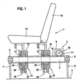
- a vehicle-mounted vehicle seat 1 is shown in a highly schematic representation.
- the vehicle seat 1 comprises a vehicle seat adjustment drive 2, which is fixed to a vehicle body floor 3.
- the vehicle seat adjustment drive 2 comprises a threaded spindle 4 running parallel to the vehicle body floor 3 and extending in the vehicle longitudinal direction.
- the threaded spindle 4 is rotatably supported by means of schematically indicated, each end arranged bearings 5, 6, wherein the bearings 5, 6 are connected via connecting elements 7, 8 fixed to the vehicle body floor 3.
- the threaded spindle 4 is associated with a trained as an electric motor drive motor 9 which rotatably carries a worm wheel 11 on its motor shaft 10, the torque transmitting with the threaded spindle 4 or with an external thread 12 of the threaded spindle 4 is engaged.
- a first rider 13 for adjusting a vehicle seat part 14 designed as a vehicle seat sits along a vehicle longitudinal axis and a second rider 15 for adjusting a second vehicle seat part 16 designed as a vehicle seat back.
- Both riders 13, 14 have an outer adjusting force transmission element 17, 18, each formed by a housing of the first and second rider 13, 15.
- the adjusting force transmission elements 17, 18 are supported in each case via two axially adjacent, not shown, optional bearings, which are arranged radially between the corresponding adjusting force transmission element 17, 18 and an associated female thread element 19, 20 (nuts), radially inward on the associated female thread element 19, 20 from ,
- the internal thread elements 19, 20 are by means of their respective internal thread 21, 22 in permanent engagement with the threaded spindle 4th
- the adjusting force transmission element 17 of the first rider 13 is connected to a merely schematically indicated lever mechanism 23 with the first vehicle seat part 14, in such a way that from the adjustment of the first rider 13 along the longitudinal extension of the threaded spindle 4, an adjusting movement of the first vehicle seat part 14th results.
- the second rider 15 or the adjusting force transmission element 18 of the second rider 15 is connected to the second vehicle seat part 16 by means of a lever mechanism 24, which is again shown only in a highly schematized manner, so that an adjustment movement of the second rider 15 results in an adjustment movement of the second vehicle seat part 16.
- each rider 13, 15 equipped with coupling means 25, 26 each comprise an electromagnetic actuator 27, 28 (coil), which adjusts an associated coupling element 29, 30, here in each case a coupling pin, in the radial direction with respect to the threaded spindle 4 with appropriate energization.
- the coupled state ie with radially inwardly adjusted coupling elements 29, 30 engage the coupling elements 29, 30 positively in each case designed as an external tooth counter-element 31, 32 of the associated internal thread element 21, 22 a.
- the adjusting force transmission element 17 of the first rider 13 is not coupled to the associated internal thread member 21, so that when rotating threaded spindle 4, the associated internal thread member 21 is rotated in place with the threaded spindle 4, the corresponding adjusting force transmission element 17 so lack of coupling not is adjusted along the threaded spindle 4, whereby the first vehicle seat part 14 retains its position.
Landscapes
- Engineering & Computer Science (AREA)
- Aviation & Aerospace Engineering (AREA)
- Transportation (AREA)
- Mechanical Engineering (AREA)
- Seats For Vehicles (AREA)
Claims (17)
- Mécanisme de réglage d'un siège de véhicule, avec une broche filetée (4) montée à rotation, avec un moteur d'entraînement électrique (9) pour entraîner la broche filetée (4), et avec au moins un cavalier (13, 15) déplaçable le long de la broche filetée (4), présentant un élément à filetage interne (19, 20) se trouvant en prise avec la broche filetée (4), pour le réglage d'un siège de véhicule (1) et/ou d'une partie d'un siège de véhicule (14, 16),
caractérisé en ce que
le cavalier (13, 15) présente un élément de transfert de force de réglage (17, 18), qui peut être accouplé par engagement par force avec l'élément à filetage interne (19, 20) à l'aide des moyens d'accouplement (25, 26), et être désaccouplé de celui-ci. - Mécanisme de réglage d'un siège de véhicule selon la revendication 1, caractérisé en ce que l'on prévoit, radialement entre l'élément de transfert de force de réglage (17, 18) et l'élément à filetage interne (19, 20) un palier (5, 6), en particulier un palier à roulement.
- Mécanisme de réglage d'un siège de véhicule selon la revendication 2, caractérisé en ce que le frottement entre l'élément à filetage interne (19, 20) et la broche filetée (4) est plus important que le frottement de palier du palier (5, 6) entre l'élément à filetage interne (19, 20) et l'élément de transfert de force de réglage (17, 18).
- Mécanisme de réglage d'un siège de véhicule selon l'une quelconque des revendications précédentes,
caractérisé en ce que les moyens d'accouplement (25, 26) sont réalisés de manière à créer un accouplement par engagement par friction. - Mécanisme de réglage d'un siège de véhicule selon l'une quelconque des revendications précédentes,
caractérisé en ce que les moyens d'accouplement (25, 26) sont réalisés de manière à créer un accouplement par engagement par correspondance géométrique. - Mécanisme de réglage d'un siège de véhicule selon la revendication 5,
caractérisé en ce que les moyens d'accouplement (25, 26) présentent un élément d'accouplement (29, 30) pouvant être actionné au moyen d'un actionneur électromagnétique (27, 28), notamment une goupille d'accouplement. - Mécanisme de réglage d'un siège de véhicule selon la revendication 6,
caractérisé en ce que l'actionneur est fixé sur l'élément de transfert de force de réglage (17, 18), et en ce que l'élément d'accouplement (29, 30) coopère par engagement par correspondance géométrique avec un élément conjugué (31, 32) sur l'élément à filetage interne (19, 20), notamment un évidement ou une saillie, dans l'état accouplé de l'arbre. - Mécanisme de réglage d'un siège de véhicule selon la revendication 7,
caractérisé en ce que l'élément conjugué (31, 32) est formé par une denture extérieure sur l'élément à filetage interne (19, 20). - Mécanisme de réglage d'un siège de véhicule selon l'une quelconque des revendications précédentes,
caractérisé en ce que l'élément à filetage interne (19, 20) est réalisé à partir de plusieurs, de préférence deux, pièces moulées, notamment identiques. - Mécanisme de réglage d'un siège de véhicule selon l'une quelconque des revendications précédentes,
caractérisé en ce que plusieurs cavaliers (13, 15) disposés les uns à côté des autres sur la broche filetée (4) sont pourvus à chaque fois d'un élément à filetage interne (19, 20) et d'un élément de transfert de force de réglage (17, 18) pouvant être accouplé à celui-ci avec des moyens d'accouplement (25, 26). - Mécanisme de réglage d'un siège de véhicule selon l'une quelconque des revendications précédentes,
caractérisé en ce qu'un cavalier (13, 15) est pourvu d'un élément à filetage interne (19, 20), qui sert d'élément de transfert de force de réglage (17, 18) ou qui est connecté fixement de manière durable à un élément de transfert de force de réglage (17, 18). - Utilisation d'un mécanisme de réglage d'un siège de véhicule (2) selon l'une quelconque des revendications précédentes, pour le réglage d'un siège de véhicule (1) et/ou d'au moins une partie de siège de véhicule (14, 16).
- Siège de véhicule comprenant un mécanisme de réglage de siège de véhicule (2) selon l'une quelconque des revendications 1 à 11.
- Siège de véhicule selon la revendication 13,
caractérisé en ce que la broche filetée (4) du mécanisme de réglage de siège de véhicule (2) est disposée au moins approximativement horizontalement. - Siège de véhicule selon l'une quelconque des revendications 13 ou 14,
caractérisé en ce qu'au moins une partie de siège de véhicule (14, 16) du siège de véhicule (1) et/ou la carrosserie du véhicule, notamment au moyen d'un mécanisme à levier (23, 24) présentant au moins un levier, notamment au moins une genouillère, est accouplée à au moins un élément de transfert de force de réglage (17, 18). - Véhicule comprenant un siège de véhicule (1) selon l'une quelconque des revendications 13 à 15.
- Véhicule selon la revendication 16,
caractérisé en ce que la broche filetée (4) du mécanisme de réglage de siège de véhicule (2) est fixée de manière rotative sur le siège de véhicule (1), notamment sur le bâti du siège de véhicule, ou sur la carrosserie du véhicule, de préférence sur le sol de la carrosserie du véhicule (3).
Applications Claiming Priority (1)
| Application Number | Priority Date | Filing Date | Title |
|---|---|---|---|
| DE200710026107 DE102007026107A1 (de) | 2007-06-05 | 2007-06-05 | Kraftfahrzeugsitzverstellantrieb |
Publications (3)
| Publication Number | Publication Date |
|---|---|
| EP2000350A2 EP2000350A2 (fr) | 2008-12-10 |
| EP2000350A3 EP2000350A3 (fr) | 2009-03-04 |
| EP2000350B1 true EP2000350B1 (fr) | 2010-06-23 |
Family
ID=39712230
Family Applications (1)
| Application Number | Title | Priority Date | Filing Date |
|---|---|---|---|
| EP20080103403 Not-in-force EP2000350B1 (fr) | 2007-06-05 | 2008-04-07 | Mécanisme de déplacement d'un siège de véhicule automobile |
Country Status (2)
| Country | Link |
|---|---|
| EP (1) | EP2000350B1 (fr) |
| DE (2) | DE102007026107A1 (fr) |
Cited By (3)
| Publication number | Priority date | Publication date | Assignee | Title |
|---|---|---|---|---|
| US11772517B2 (en) | 2020-11-09 | 2023-10-03 | Ford Global Technologies, Llc | Vehicular system capable of adjusting a passenger compartment from a child seat arrangement to a second arrangement |
| US11904732B2 (en) | 2020-11-09 | 2024-02-20 | Ford Global Technologies, Llc | Vehicular system capable of adjusting a passenger compartment from a first arrangement to a child care arrangement |
| US12077068B2 (en) | 2020-11-09 | 2024-09-03 | Ford Global Technologies, Llc | Authorization-based adjustment of passenger compartment arrangement |
Family Cites Families (2)
| Publication number | Priority date | Publication date | Assignee | Title |
|---|---|---|---|---|
| DE4317348A1 (de) * | 1993-05-25 | 1994-12-01 | Grammer Ag | In ihrer Länge veränderbare Verstelleinrichtung |
| US5797293A (en) * | 1996-12-19 | 1998-08-25 | Lear Corporation | Plastic drive block for vehicle seat adjuster |
-
2007
- 2007-06-05 DE DE200710026107 patent/DE102007026107A1/de not_active Withdrawn
-
2008
- 2008-04-07 EP EP20080103403 patent/EP2000350B1/fr not_active Not-in-force
- 2008-04-07 DE DE200850000815 patent/DE502008000815D1/de active Active
Cited By (3)
| Publication number | Priority date | Publication date | Assignee | Title |
|---|---|---|---|---|
| US11772517B2 (en) | 2020-11-09 | 2023-10-03 | Ford Global Technologies, Llc | Vehicular system capable of adjusting a passenger compartment from a child seat arrangement to a second arrangement |
| US11904732B2 (en) | 2020-11-09 | 2024-02-20 | Ford Global Technologies, Llc | Vehicular system capable of adjusting a passenger compartment from a first arrangement to a child care arrangement |
| US12077068B2 (en) | 2020-11-09 | 2024-09-03 | Ford Global Technologies, Llc | Authorization-based adjustment of passenger compartment arrangement |
Also Published As
| Publication number | Publication date |
|---|---|
| EP2000350A2 (fr) | 2008-12-10 |
| EP2000350A3 (fr) | 2009-03-04 |
| DE502008000815D1 (de) | 2010-08-05 |
| DE102007026107A1 (de) | 2008-12-11 |
Similar Documents
| Publication | Publication Date | Title |
|---|---|---|
| EP2086372B1 (fr) | Dispositif d'entraînement pour des éléments mobiles de meubles | |
| DE102008034800A1 (de) | Verstelleinrichtung, insbesondere für einen Fahrzeugsitz | |
| DE102018203453B4 (de) | Baugruppensystem für den Antrieb eines Kraftfahrzeugs mit elektrischer Antriebsmaschine | |
| DE102017205721A1 (de) | Getriebeeinheit für ein Kraftfahrzeug | |
| DE10337629A1 (de) | Antrieb | |
| DE202017102066U1 (de) | Spindelantrieb zur motorischen Verstellung eines Verstellelements eines Kraftfahrzeugs | |
| DE10200169A1 (de) | Möbelantrieb zum Verstellen von Teilen eines Möbels relativ zueinander | |
| EP1284447A1 (fr) | Ferrure pivotante | |
| EP1453638A1 (fr) | Dispositif pour fixer un outil sur un arbre et broche de machine comportant un tel dispositif | |
| DE102005045614A1 (de) | Anlasser, der mit einem Zweistufen-Drehzahluntersetzungsgetriebemechanismus ausgestattet ist | |
| EP2000350B1 (fr) | Mécanisme de déplacement d'un siège de véhicule automobile | |
| DE102021213456A1 (de) | Spindelantrieb sowie Verfahren zum Betreiben eines solchen | |
| EP1412636A1 (fr) | Demarreur | |
| DE102013209310A1 (de) | Schaltbares Planetengetriebe | |
| WO2012152727A2 (fr) | Ensemble engrenage planétaire pour un mécanisme de réglage de siège et procédé de fonctionnement d'un ensemble engrenage planétaire de ce type | |
| DE102008063352A1 (de) | Verstellbares Schwenkgelenk eines Kraftfahrzeugsitzes | |
| DE102008061606A1 (de) | Bremsvorrichtung und Motor mit Geschwindigkeitsreduzierungsmechanismus | |
| DE102008041335A1 (de) | Lenkgetriebe und damit ausgestattete Servolenkung | |
| EP3482480B1 (fr) | Dispositif de fixation d'un moteur électrique et siège | |
| EP2336495A1 (fr) | Turbosoufflante de gaz d'échappement | |
| WO2019121626A1 (fr) | Ensemble de transmission pour un motoréducteur d'un frein à actionnement électrique, motoréducteur, système de frein à main et système de pédale de frein | |
| DE202017102027U1 (de) | Getriebeeinheit für ein Kraftfahrzeug | |
| DE3346608C2 (fr) | ||
| EP1140553B1 (fr) | Dispositif d'entrainement pour deplacer des elements d'unites faisant partie d'un vehicule automobile | |
| DE10003512B4 (de) | Vorrichtung zur Unterstützung der Selbsthemmung bei Elektromotoren |
Legal Events
| Date | Code | Title | Description |
|---|---|---|---|
| PUAI | Public reference made under article 153(3) epc to a published international application that has entered the european phase |
Free format text: ORIGINAL CODE: 0009012 |
|
| AK | Designated contracting states |
Kind code of ref document: A2 Designated state(s): AT BE BG CH CY CZ DE DK EE ES FI FR GB GR HR HU IE IS IT LI LT LU LV MC MT NL NO PL PT RO SE SI SK TR |
|
| AX | Request for extension of the european patent |
Extension state: AL BA MK RS |
|
| PUAL | Search report despatched |
Free format text: ORIGINAL CODE: 0009013 |
|
| AK | Designated contracting states |
Kind code of ref document: A3 Designated state(s): AT BE BG CH CY CZ DE DK EE ES FI FR GB GR HR HU IE IS IT LI LT LU LV MC MT NL NO PL PT RO SE SI SK TR |
|
| AX | Request for extension of the european patent |
Extension state: AL BA MK RS |
|
| 17P | Request for examination filed |
Effective date: 20090904 |
|
| AKX | Designation fees paid |
Designated state(s): DE ES FR IT |
|
| GRAP | Despatch of communication of intention to grant a patent |
Free format text: ORIGINAL CODE: EPIDOSNIGR1 |
|
| GRAS | Grant fee paid |
Free format text: ORIGINAL CODE: EPIDOSNIGR3 |
|
| GRAA | (expected) grant |
Free format text: ORIGINAL CODE: 0009210 |
|
| AK | Designated contracting states |
Kind code of ref document: B1 Designated state(s): DE ES FR IT |
|
| REF | Corresponds to: |
Ref document number: 502008000815 Country of ref document: DE Date of ref document: 20100805 Kind code of ref document: P |
|
| PG25 | Lapsed in a contracting state [announced via postgrant information from national office to epo] |
Ref country code: IT Free format text: LAPSE BECAUSE OF FAILURE TO SUBMIT A TRANSLATION OF THE DESCRIPTION OR TO PAY THE FEE WITHIN THE PRESCRIBED TIME-LIMIT Effective date: 20100623 |
|
| PLBE | No opposition filed within time limit |
Free format text: ORIGINAL CODE: 0009261 |
|
| STAA | Information on the status of an ep patent application or granted ep patent |
Free format text: STATUS: NO OPPOSITION FILED WITHIN TIME LIMIT |
|
| 26N | No opposition filed |
Effective date: 20110324 |
|
| REG | Reference to a national code |
Ref country code: DE Ref legal event code: R097 Ref document number: 502008000815 Country of ref document: DE Effective date: 20110323 |
|
| PGFP | Annual fee paid to national office [announced via postgrant information from national office to epo] |
Ref country code: FR Payment date: 20110427 Year of fee payment: 4 |
|
| REG | Reference to a national code |
Ref country code: DE Ref legal event code: R084 Ref document number: 502008000815 Country of ref document: DE Effective date: 20111025 |
|
| REG | Reference to a national code |
Ref country code: FR Ref legal event code: ST Effective date: 20121228 |
|
| PG25 | Lapsed in a contracting state [announced via postgrant information from national office to epo] |
Ref country code: FR Free format text: LAPSE BECAUSE OF NON-PAYMENT OF DUE FEES Effective date: 20120430 |
|
| PG25 | Lapsed in a contracting state [announced via postgrant information from national office to epo] |
Ref country code: ES Free format text: LAPSE BECAUSE OF FAILURE TO SUBMIT A TRANSLATION OF THE DESCRIPTION OR TO PAY THE FEE WITHIN THE PRESCRIBED TIME-LIMIT Effective date: 20101004 |
|
| PGFP | Annual fee paid to national office [announced via postgrant information from national office to epo] |
Ref country code: DE Payment date: 20200623 Year of fee payment: 13 |
|
| REG | Reference to a national code |
Ref country code: DE Ref legal event code: R119 Ref document number: 502008000815 Country of ref document: DE |
|
| PG25 | Lapsed in a contracting state [announced via postgrant information from national office to epo] |
Ref country code: DE Free format text: LAPSE BECAUSE OF NON-PAYMENT OF DUE FEES Effective date: 20211103 |