EP2000224A1 - Ringwalzwerk und ringwalzverfahren - Google Patents
Ringwalzwerk und ringwalzverfahren Download PDFInfo
- Publication number
- EP2000224A1 EP2000224A1 EP07740115A EP07740115A EP2000224A1 EP 2000224 A1 EP2000224 A1 EP 2000224A1 EP 07740115 A EP07740115 A EP 07740115A EP 07740115 A EP07740115 A EP 07740115A EP 2000224 A1 EP2000224 A1 EP 2000224A1
- Authority
- EP
- European Patent Office
- Prior art keywords
- mandrel
- main roll
- ring
- shaped body
- outer peripheral
- Prior art date
- Legal status (The legal status is an assumption and is not a legal conclusion. Google has not performed a legal analysis and makes no representation as to the accuracy of the status listed.)
- Granted
Links
Images







Classifications
-
- B—PERFORMING OPERATIONS; TRANSPORTING
- B21—MECHANICAL METAL-WORKING WITHOUT ESSENTIALLY REMOVING MATERIAL; PUNCHING METAL
- B21B—ROLLING OF METAL
- B21B17/00—Tube-rolling by rollers of which the axes are arranged essentially perpendicular to the axis of the work, e.g. "axial" tube-rolling
- B21B17/02—Tube-rolling by rollers of which the axes are arranged essentially perpendicular to the axis of the work, e.g. "axial" tube-rolling with mandrel, i.e. the mandrel rod contacts the rolled tube over the rod length
-
- B—PERFORMING OPERATIONS; TRANSPORTING
- B21—MECHANICAL METAL-WORKING WITHOUT ESSENTIALLY REMOVING MATERIAL; PUNCHING METAL
- B21B—ROLLING OF METAL
- B21B5/00—Extending closed shapes of metal bands by rolling
-
- B—PERFORMING OPERATIONS; TRANSPORTING
- B21—MECHANICAL METAL-WORKING WITHOUT ESSENTIALLY REMOVING MATERIAL; PUNCHING METAL
- B21H—MAKING PARTICULAR METAL OBJECTS BY ROLLING, e.g. SCREWS, WHEELS, RINGS, BARRELS, BALLS
- B21H1/00—Making articles shaped as bodies of revolution
- B21H1/06—Making articles shaped as bodies of revolution rings of restricted axial length
Definitions
- the present invention relates to a ring rolling mill and a ring rolling method which roll a peripheral portion of a ring-shaped body in a radial direction.
- This application is based on Japanese Patent Application No. 2006-089750 , the content of which is incorporated herein by reference.
- a conventional ring rolling mill disclosed in Patent Document 1, etc. rolls a peripheral portion of a ring-shaped body in a radial direction while the ring-shaped body is rotated in its peripheral direction, with the peripheral portion pinched in the radial direction between an outer peripheral surface of a main roll which is rotationally driven, and an outer peripheral surface of a mandrel which is rotatable.
- the peripheral portion of the ring-shaped body is rolled in the radial direction by the outer peripheral surfaces of the main roll and the mandrel by relatively bringing or separating the main roll and the mandrel close to or from each other in a state where their axes of rotation are kept substantially parallel to each other.
- the main roll and the mandrel are brought close to or separated from each other in a state where their axes of rotation are kept substantially parallel to each other.
- the pressing forces applied on the peripheral portion of the ring-shaped body by the main roll and the mandrel could be made different in every peripheral position on the peripheral portion, but could not be made different in every position in the thickness direction. That is, the pressing forces could not be made different locally in the peripheral portion of the ring-shaped body.
- the invention has been made in view of the above circumstances.
- the object of the invention is to provide a ring rolling mill and a ring rolling method capable of making pressing forces applied on a peripheral portion of a ring-shaped body by a main roll and a mandrel made different locally in the peripheral portion of the ring-shaped body.
- the invention has adopted the followings.
- the pressing forces applied on the peripheral portion of the ring-shaped body by the main roll and the mandrel can be made different locally in the peripheral portion of the ring-shaped body.
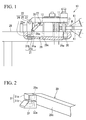
- a ring rolling mill 10 of this embodiment includes a main roll 11 and a mandrel 21 which are provided so as to be capable of being brought close to or separated from each other.
- a peripheral portion of a ring-shaped body W pinched in its radial direction between an outer peripheral surface of the main roll 11 which is rotationally driven around its axis, and an outer peripheral surface of the mandrel 21 which is rotatable around its axis, the peripheral portion is rolled in the radial direction while the ring-shaped body W is rotated in its peripheral direction.
- the ring-shaped body W is formed by slab-forging melted ingot, and then forming a through hole in this ingot.
- a pair of axial rolls 41 which pinches the ring-shaped body W in its thickness direction is provided so as to be capable of being rotationally driven around their axes of rotation.
- the axial rolls 41 are supported so as to be capable of advancing and retreating along the radial direction of the ring-shaped body W.
- the main roll 11 is supported by a fixed frame 12 so as to be capable of being rotationally driven around its axis of rotation in a state where its axis of rotation runs along a vertical direction.
- the outer peripheral surface of the main roll 11 supports an outer peripheral surface of the ring-shaped body W.
- the mandrel 21 is supported so as to be rotatable around its axis of rotation with respect to a movable frame 22 in a state where its axis of rotation is substantially parallel to the axis of rotation of the main roll 11.
- the inner peripheral surface of the ring-shaped body W presses the outer peripheral surface of the mandrel 21 outward in its radial direction.
- the movable frame 22 includes a pair of upper frames 23 which extend horizontally toward the main roll 11 from the mandrel 21, a pair of lower frames 24 which are provided vertically below the upper frames 23 and extend substantially parallel to an extension direction of the upper frames 23, and an intermediate frame 25 which connects each upper frame 23 and each lower frame 24.
- the intermediate frame 25 connects the rear end of each upper frame 23 and the rear end of each lower frame 24 opposite their front ends on the side where the mandrel 21 is disposed.
- Bridging frames (not shown) which connect the pair of upper frames 23 and the pair of lower frames 24, respectively, are disposed at the front end of each upper frame 23 and at the front end of each lower frame 24, respectively. Both ends of the mandrel 21 in the direction of its axis of rotation are supported by these bridging frames so as to be rotatable around the axis of the mandrel.
- Each upper frame 23 is supported so as to be rotatable in the vertical direction about a pin 25a inserted through the intermediate frame 25.
- a base end of an opening/closing cylinder 26 is attached to the intermediate frame 25.
- a distal end of a rod of the cylinder 26 is attached to a lower surface of the upper frame 23.
- the intermediate frame 25 is provided with an advance/retreat driving cylinder 27. Also, the distal end of the rod of the advance/retreat driving cylinder 27 is connected with the fixed frame 12 which supports the main roll 11. Consequently, if the advance/retreat driving cylinder 27 is driven to advance and retreat, the reaction force from the fixed frame 12 acts on the intermediate frame 25, and the whole movable frame 22 including the intermediate frame 25, the upper frame 23, the lower frame 24, and each of the bridging frame moves horizontally along with the mandrel 21.
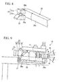
- the lower frames 24 are supported by a pair of rail portions 28, respectively, which extend substantially parallel to the extension direction of the frames 24.
- Each lower frame 24 includes a pair of lower frame bodies 29 which extend horizontally toward the main roll 11 from the mandrel 21, and first and second fitting projections 30 and 31 which are respectively provided at both longitudinal ends of each of outer lateral surface 29c opposite the inner lateral surfaces which face each other, among outer surfaces of the lower frame bodies 29. That is, the front end of both the longitudinal ends of the outer lateral surface 29c on the side where the mandrel 21 is disposed is provided with the first fitting projection 30, and the rear end opposite the front end is provided with the second fitting projection 31.
- the first and second fitting projections 30 and 31 are slidably fitted into grooves 28a, respectively, which are formed in the inner lateral surfaces which face each other in the pair of rail portions 28, the lower frames 24 are supported by the rail portions 28. Further, as the pins 29a provided so as to protrude from both the longitudinal ends on the outer lateral surface 29c of the lower frame body 29 are fitted into holes, respectively, which are formed in the first and second fitting projections 30 and 31, respectively, the first and second fitting projections 30 and 31 are rotatably supported about the pins 29a.
- the first fitting projection 30 is such that a portion into which the pin 29a of the lower frame body 29 is fitted, and a portion which is fitted into the groove 28a of the rail portion 28 are formed integrally.
- the second fitting projection 31 includes an upper fitting projection 31a which is rotatably fitted into the pin 29a of the lower frame body 29, and a lower fitting projection 31b which is arranged below the upper fitting projection 31a, and is slidably fitted into the groove 28a of the rail portion 28.
- An elevating cylinder 32 which can advance and retreat in the vertical direction is provided inside the lower fitting projection 31b.
- the upper fitting projection 31a and the lower fitting projection 31b are connected together via a rod 32a of the cylinder 32.
- the axis of rotation of the mandrel 21 attached between the bridging frames of the movable frame 22 is inclined such that a gap between a vertical upper portion of the outer peripheral surface of the mandrel 21, and the outer peripheral surface of the main roll 11 becomes smaller than a gap between a vertical lower portion of the outer peripheral surface of the mandrel, and the outer peripheral surface of the main roll 11.
- the axis of rotation of the mandrel 21 attached to the rotary frame 22 is inclined such that a gap between the vertical lower portion of the outer peripheral surface of the mandrel 21, and the outer peripheral surface of the main roll 11 becomes smaller than a gap between the vertical upper portion of the outer peripheral surface of the mandrel, and the outer peripheral surface of the main roll 11.
- the mandrel 21 is supported so as to be capable of being inclined with respect to the axis of rotation of the main roll 11 such that the gap dimension between the outer peripheral surface of the mandrel and the outer peripheral surface of the main roll 11 differ on one side and the other side in the direction of its axis of rotation.
- a ring rolling method using the ring rolling mill 10 of this embodiment will be described below.
- the advance/retreat driving cylinder 27 is retreated to separate the main roll 11 and the mandrel 21 from each other, and to retreat the axial rolls 41 with respect to the ring-shaped body W.
- the opening/closing cylinder 26 is extended to rotate the upper frame 23 vertically upward along with the mandrel 21 about the pin 25a inserted through the intermediate frame 25, the ring-shaped body W is arranged.
- the opening/closing cylinder 26 is retracted to rotate the upper frame 23 vertically downward about the pin 25a along with the mandrel 21.
- the outer peripheral surface of the main roll 11 and the outer peripheral surface of the ring-shaped body W are made to face each other, and the outer peripheral surface of the mandrel 21 and the inner peripheral surface of the ring-shaped body W are made to face each other.
- the pair of axial rolls 41 are advanced toward the ring-shaped body W, and the ring-shaped body W is pinched in its thickness direction by the outer peripheral surface of these axial rolls 41.
- the advance/retreat driving cylinder 27 is extended to bringing the mandrel 21 close to the main roll 11.
- the peripheral portion of the ring-shaped body W is pinched in its radial direction between the outer peripheral surface of the mandrel 21 and the outer peripheral surface of the main roll 11.
- the ring-shaped body W is rotated in its peripheral direction by rotationally driving the main roll 11 and the axial rolls 41 about each axis of rotation. Then, while the mandrel 21 rotates about its axis of rotation, the peripheral portion of the ring-shaped body W is rolled in its radial direction over its whole periphery. In this rolling process, as the thickness of the peripheral portion of the ring-shaped body W in its radial direction becomes smaller, the mandrel 21 gradually advances toward the outer peripheral surface of the main roll 11 by the pressing force to the fixed frame 12 by the advance/retreat driving cylinder 27. Moreover, in this rolling process, as the diameter of the ring-shaped body W increases, the axial rolls 41 gradually retreats radially outward of the ring-shaped body W.
- each elevating cylinder 32 is extended or retracted from its parallel state.
- the axis of rotation of the mandrel 21 is inclined with respect to the axis of rotation of the main roll 11 such that the gap between the outer peripheral surface of the mandrel and the outer peripheral surface of the main roll 11 differs on one side and the other side in the direction of its axis of rotation.
- the pressing force applied on the ring-shaped body W can be changed along its axis direction.
- the taper of the ring-shaped body W can also be removed utilizing a rocking mechanism of the mandrel 21 in the ring rolling mill 10. This will be described with reference to FIGS. 10A to 10C . As shown in FIG.
- the ring-shaped body W when any variation exists in the material shape of the ring-shaped body W in a case where the ring-shaped body can be normally rolled with constant thickness along its axis, the ring-shaped body W may be tapered as shown in, for example, FIG. 10B . In such a case, as shown in FIG. 10C , the taper of the ring-shaped body W can be removed by performing rolling while the mandrel 21 is inclined at a proper angle with respect to the main roll 11.
- the movable frame 22 includes each upper frame 23 and each lower frame 24 (supporting frame) which support upper and lower ends of the mandrel 21; and the second fitting projection 31 (frame tilting mechanism) which tilts the upper frame 23 and the lower frame 24 is adopted.
- the pressing forces applied on the peripheral portion of the ring-shaped body W by the main roll 11 and the mandrel 21 can be made different not only along every peripheral position of the peripheral portion, but also along positions in the thickness direction.
- the pressing forces can be made different in every portion rolled in the peripheral portion of the ring-shaped body W, that is, locally.
- the inclination angle of the mandrel can be made different two or more times, or the mandrel can be kept at the same inclination angle while the ring-shaped body makes one rotation.
- the mandrel 21 is inclinedly supported, when the peripheral portion of the ring-shaped body W is rolled over the whole area in its thickness direction, the mandrel 21 is inclined such that the gap between the outer peripheral surface of the mandrel and the outer peripheral surface of the main roll 11 becomes smaller on one side in the direction of its axis of rotation than on the other side in the direction of its axis of rotation.
- the portion of the peripheral portion of the ring-shaped body W which faces the portion of the outer peripheral surface of the mandrel 21 on the other side in the direction of the axis of rotation can be rolled over its whole periphery by inclining the mandrel 21 such that the gap becomes smaller on the other side in the direction of its axis of rotation than on one side in the direction of its axis of rotation after the portion of the peripheral portion of the ring-shaped body W which faces the portion of the outer peripheral surface of the mandrel 21 on one side in the direction of the axis of rotation.
- both an increase in the rolling amount of the ring rolling mill 10 and the compactness thereof can be made compatible with each other.
- the ring-shaped body W can be rolled while being rotated in its peripheral direction without being removed from the ring rolling mill 10, the efficiency of processing can also be made high.
- the mandrel 21 is inclined by rotating the whole movable frame 22 in the vertical direction, whereas in the ring rolling mill 110 of this embodiment, the mandrel 21 is inclined by horizontally translating a member (hereinafter, upper frame 123) equivalent to the upper frame 23.
- upper frame 123 a member equivalent to the upper frame 23.
- a ring rolling mill 110 of this embodiment includes a tilting frame 122 as the mandrel inclining/supporting mechanism of the present invention.
- the tilting frame 122 includes a pair of upper frames 123 which extend horizontally toward the main roll 11 from the mandrel 21, a pair of lower frames 124 which are provided vertically below the upper frames 123 and extend substantially parallel to an extension direction of the upper frames 123, and an intermediate frame 125 which connects each upper frame 123 and each lower frame 124.
- the intermediate frame 125 connects the rear end of each upper frame 123 and the rear end of each lower frame 124 opposite their front ends on the side where the mandrel 21 is disposed.
- illustration of the rail portions 28 is omitted for the purpose of explanation. This is also the same in the following third to fifth embodiments.
- Bridging frames (not shown) which connect the pair of upper frames 123 and the pair of lower frames 124, respectively, are disposed at the front end of each upper frame 123 and at the front end of each lower frame 124, respectively. Both ends of the mandrel 21 in the direction of its axis of rotation are supported by these bridging frames so as to be rotatable around the vertical axis of the mandrel.
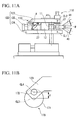
- the bridging frame (first mandrel supporting portion) between the lower frames 124 rotatably supports a lower end (one end) of the mandrel 21 in place around a horizontal axis (that is, an axis vertical to the sheet plane of FIG.
- the bridging frame (second mandrel supporting portion) between the upper frames 123 rotatably supports an upper end (other end) of the mandrel 21 around the horizontal axis (that is, an axis vertical to the sheet plane of FIG. 11A ) in a position which intersects the axis of rotation of the mandrel 21 and is twisted with respect to the axis of rotation of the main roll 11.
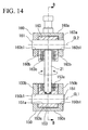
- the supporting structure of the mandrel 21 will be described in detail, referring to FIGS. 14 and 15 .
- the bridging frame between the lower frames 124 is provided with a fixed portion 150 which is integrally attached to this bridging frame, a horizontal shaft 151 fixed to the fixed portion 150, and a rotary portion 153 which is attached to the horizontal shaft 151 so as to be rotatable about a horizontal axis CL1.
- the fixed portion 150 includes a bottom wall 150a, and a pair of side walls 150b formed vertically upward from both ends of the bottom wall 150a.
- a through hole 150b1 for allowing the horizontal shaft 151 to be inserted therethrough is formed along the horizontal direction in each side wall 150b.
- the upper surface of the bottom wall 150a defines a circular-arc surface 150a1 as seen in a cross-section vertical to the horizontal axis CL1.
- the rotary portion 153 is arranged between the side walls 150b, and includes a rotary portion main body 153a in which a through hole 151 a through which the horizontal shaft 151 is inserted along the horizontal direction, and a thrust bearing 153b and an axial bearing 153c which are provided inside an opening formed at an upper end of the rotary portion main body 153a.
- the thrust bearing 153b supports the thrust load by the mandrel 21, and the axial bearing 153c supports the bending load which acts on the mandrel 21.
- a lower end of the mandrel 21 is rotatably supported about the axis of the mandrel by the thrust bearing 153b and the axial bearing 153c.
- a lower surface of the rotary portion main body 153a defines a circular-arc surface 153a1 which forms a fixed gap with respect to the circular-arc surface 150a1, and interferes with the fixed portion 150 during the rotation of the rotary portion main body 153a. Accordingly, the thrust load and bending load of the mandrel 21 are transmitted to the thrust bearing 153b and axial bearing 153c, the rotary portion main body 153a, the horizontal shaft 151, each side wall 150b, and the bridging frame between the lower frames 124.
- the bridging frame between the upper frames 123 is provided with a fixed portion 160 which is integrally attached to this bridging frame, a horizontal shaft 161 fixed to the fixed portion 160, and a rotary portion 163 which is attached to the horizontal shaft 161 so as to be rotatable about a horizontal axis CL2.
- the fixed portion 160 includes a top wall 160a, and a pair of side walls 160b formed vertically downward from both ends of the top wall 160a.
- a through hole 160b1 for allowing the horizontal shaft 161 to be inserted therethrough is formed along the horizontal direction in each side wall 160b.
- the lower surface of the top wall 160a defines a circular-arc surface 160a1 as seen in a cross-section vertical to the horizontal axis CL.
- the rotary portion 163 is arranged between the side walls 160b, and includes a rotary portion main body 163a in which a through hole 161a through which the horizontal shaft 161 is inserted along the horizontal direction, and a thrust bearing 163c which is provided inside an opening formed at a lower end of the rotary portion main body 163a.
- the axial bearing 163c supports the bending load which acts on the mandrel 21.
- An upper end of the mandrel 21 is rotatably supported about the axis of the mandrel by the axial bearing 163c.
- an upper surface of the rotary portion main body 163a defines a circular-arc surface 163a1 which forms a fixed gap with respect to the circular-arc surface 160a1, and interferes with the fixed portion 160 during the rotation of the rotary portion main body 163a. Accordingly, the bending load of the mandrel 21 is transmitted to the axial bearing 163c, the rotary portion main body 163a, the horizontal shaft 161, each side wall 160b, and the bridging frame between the lower frames 123.
- the fixed portion 150 which supports the lower end of the mandrel 21 is fixed in place along with the bridging frame arranged between the lower frames 124, while the fixed portion 160 which supports the upper end of the mandrel 21 moves in the horizontal direction along with the bridging frame arranged between the upper frames 123.
- the mandrel 21 can be rocked so as to be brought close to or separated from the main roll 11 while the mandrel is kept rotatable around its axis of rotation.
- the ring rolling mill 110 of this embodiment is equipped with a driving section 170 (first mandrel driving section) which brings or separates the bridging frame (second mandrel supporting portion) between the upper frames 123 close to or from the main roll 11.
- This driving section 170 includes an eccentric shaft 171 which is laid between the intermediate frames 125 in place on each lower frame 124 and has a horizontal axis CL3 extending parallel to the horizontal axes CL1 and CL2; the upper frame 123 (first connecting frame) which connects the eccentric shaft 171, and the bridging frame between the upper frames 123; and a rotation driving portion (not shown) which rotates the eccentric shaft 171 around the horizontal axis CL3.
- Pins 172 which are parallel to the horizontal axis CL3 and are provided in positions which are made eccentric by eccentricity d are respectively provided at both ends of the eccentric shaft 171.
- a ring rolling method using the ring rolling mill 110 of this embodiment having the configuration described above will be described below.
- the rotation driving portion is started to rotate the eccentric shaft 171 in one direction.
- each upper frame 123 slides to the right in the figure. Therefore, the bridging frame laid between the upper frames 123 also moves to the right in the figure.
- the upper end of the mandrel 21 also moves to the right in the figure.
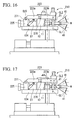
- the mandrel 21 can be inclined and supported with respect to the axis of rotation of the main roll 11 such that the gap between the outer peripheral surface of the mandrel 21 and the outer peripheral surface of the main roll 11 becomes narrower on the lower side (the other side) than on the upper side (one side) as seen in a direction along the axis of rotation of the main roll 11.
- the mandrel 21 can be inclined and supported with respect to the axis of rotation of the main roll 11 such that the gap between the outer peripheral surface of the mandrel 21 and the outer peripheral surface of the main roll 11 becomes narrower on the upper side (the other side) than on the lower side (one side) as seen in a direction along the axis of rotation of the main roll 11.
- the operation in which the mandrel 21 is brought close to or separated from the main roll 11 in a state where the inclining of the mandrel 21 is fixed can be performed by driving to advance/retreat the advance/retreat driving cylinder 27, and horizontally moving the whole tilting frame 122 to the right and left in the figure.
- the same operational effects as those of the ring rolling mill 10 of the above first embodiment can be obtained. That is, according to the ring rolling mill 110 of this embodiment, the pressing forces applied on the peripheral portion of the ring-shaped body W by the main roll 11 and the mandrel 21 can be made different not only along every peripheral position of the peripheral portion, but along positions in the thickness direction.
- each upper frame 123 is made to slide by the rotation of the eccentric shaft 171, whereas in the ring rolling mill 210 of this embodiment, the mandrel 21 is tilted by horizontally expanding and retracting a member (hereinafter, upper frame 223) equivalent to the upper frame 123.
- upper frame 223 a member equivalent to the upper frame 123.
- the ring rolling mill 210 of this embodiment includes a pair of intermediate frames 225 which form base portions fixed in place on the lower frames 124, respectively; a shaft body 271 which is laid between the intermediate frames 225, and has a horizontal axis CL5 parallel to the horizontal axes CL1 and CL2; a pair of upper frames 223 which are rotatably connected to the shaft body 271, and extend horizontally toward the main roll 11 from the mandrel 21.
- Each upper frame 223 includes a fixed-side frame 223 a which is rotatably attached to the shaft body 271; a sliding-side frame 223b which is attached to a tip of the fixed-side frame 223a so as to be movable in the horizontal direction; and a sliding driving portion 270 which brings or separates the sliding-side frame 223b close to or from the fixed-side frame 223a along the horizontal direction.
- a bridging frame (not shown) which connects the front ends is disposed.
- the front end of the mandrel 21 in the direction of its axis of rotation is supported by this bridging frame so as to be rotatable around the vertical axis of the mandrel.
- each fixed-side frame 223a constitutes the base portion of the invention
- the sliding frame 223b constitutes a second connecting frame of the invention.
- each sliding-side frame 223b is made to slide to the right in the figure by extending the sliding driving portion 270. Then, the bridging frame laid between the sliding-side frames 223b also moves to the right in the figure. As a result, the upper end of the mandrel 21 also moves to the right in the figure.
- the mandrel 21 can be inclined and supported with respect to the axis of rotation of the main roll 11 such that the gap between the outer peripheral surface of the mandrel 21 and the outer peripheral surface of the main roll 11 becomes narrower on the lower side (the other side) than on the upper side (one side) as seen in a direction along the axis of rotation of the main roll 11.
- each sliding-side frame 223b is made to slide to the left in the figure by retracting the sliding driving portion 270. Then, the bridging frame laid between the sliding-side frames 223b also moves to the left in the figure. As a result, the upper end of the mandrel 21 also moves to the left in the figure.
- the mandrel 21 can be inclined and supported with respect to the axis of rotation of the main roll 11 such that the gap between the outer peripheral surface of the mandrel 21 and the outer peripheral surface of the main roll 11 becomes narrower on the upper side (the other side) than on the lower side (one side) as seen in a direction along the axis of rotation of the main roll 11.
- the operation in which the mandrel 21 is brought close to or separated from the main roll 11 in a state where the inclining of the mandrel 21 is fixed can be performed by driving to advance/retreat the advance/retreat driving cylinder 27, and horizontally moving the whole tilting frame 122 to the right and left in the figure.
- the same operational effects as those of the ring rolling mill 110 of the above second embodiment can be obtained. That is, according to the ring rolling mill 210 of this embodiment, the pressing forces applied on the peripheral portion of the ring-shaped body W by the main roll 11 and the mandrel 21 can be made different not only along every peripheral position of the peripheral portion, but also along positions in the thickness direction.
- FIGS. 19 to 21 a fourth embodiment of the invention will be described below, referring to FIGS. 19 to 21 .
- differences from those of the second embodiment will be mainly described, and the other points are the same as those of the second embodiment, and the description thereof is omitted.
- a portion on the side of the mandrel 21 is rocked, whereas in a ring rolling mill 310 of this embodiment, a portion on the side of the main roll 11 is rocked.
- This embodiment is particularly different from the above second embodiment in regard to this point.
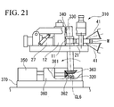
- the ring rolling mill 310 of this embodiment includes a main roll inclining/supporting mechanism which inclines and supports the main roll 11 with respect to the axis of rotation of the mandrel 21 such that the gap between the outer peripheral surface of the mandrel 21 and the outer peripheral surface of the main roll 11 differs on vertical upper side (one side) and on vertical lower side (other side) as seen in a direction along the axis of rotation of the mandrel 21.
- This main roll inclining/supporting mechanism includes a spherical bearing 320 (first main roll supporting portion) which rotatably supports the lower end (one end) of the main roll 11 in place, an upper bearing 330 (second main roll supporting portion) which rotatably supports the upper end (other end) of the main roll 11, and a main roll driving portion 340 (first main roll driving portion) which brings or separates the upper bearing 330 close to or from the mandrel 21.
- the ring rolling mill 310 of this embodiment further includes a main roll driving source 350 which generates a driving force which rotates the main roll 11, a transmission section 360 which transmits a rotational driving force from the main roll driving source 350 to the main roll 11, and a pedestal 370 on which the main roll driving source 350 and the transmission section 360 are installed.
- the transmission section 360 is provided with a gear mechanism 361 for transmitting a rotational driving force from the main roll driving source 350, and the spherical bearing 320 which supports the lower end of the main roll 11 so that the main roll 11 can be rocked in a direction in which it is brought close to or separated from the mandrel 21.
- the gear mechanism 361 and the lower end of the main roll 11 are connected together via bevel gears 362 and 363, and the rotational driving force from the main roll driving source 350 is transmitted to the gear mechanism 361, the bevel gears 362 and 363, and the main roll 11. Even if the main roll 11 rocks during transmission of this rotational driving force, a bending joint (not shown) is provided in the gear mechanism 361 so that the engagement between the bevel gears 362 and 363 may be maintained suitably.
- the main roll driving portion 340 is a hydraulic cylinder provided between the fixed frame 12 and the upper bearing 330, and brings or separates the main roll 11 close to or from the fixed frame 12 as the driving portion itself performs extension/retraction operation.
- the main roll 11 since the lower end of the main roll 11 is rockably supported on the spherical bearing 320, the main roll 11 can be tilted around a horizontal axis CL6 vertical to the sheet plane so that it can be brought close to or separated from the mandrel 21 fixed in place by driving the main roll driving portion 340.
- the horizontal axis CL6 is in a position which intersects the axis of the main roll 11, and is twisted with respect to the axis of the mandrel 21.
- a ring rolling method using the ring rolling mill 310 of this embodiment having the configuration described above will be described below.
- the main roll 11 is tilted to the right in the figure about the horizontal axis CL6 by driving the main roll driving portion 340 to extend it.
- the main roll driving portion 340 By stopping the main roll driving portion 340 in a state where the main roll 11 is inclined at a desired angle in this way, as shown in FIG.
- the mandrel 21 can be inclined and supported with respect to the axis of rotation of the main roll 11 such that the gap between the outer peripheral surface of the mandrel 21 and the outer peripheral surface of the main roll 11 becomes narrower on the upper side (the other side) than on the lower side (one side) as seen in a direction along the axis of rotation of the main roll 11.
- the main roll 11 is tilted to the left in the figure about the horizontal axis CL6 by driving the main roll driving portion 340 to retract it.
- the main roll driving portion 340 By stopping the main roll driving portion 340 in a state where the main roll 11 is inclined at a desired angle in this way, as shown in FIG.
- the mandrel 21 can be inclined and supported with respect to the axis of rotation of the main roll 11 such that the gap between the outer peripheral surface of the mandrel 21 and the outer peripheral surface of the main roll 11 becomes narrower on the lower side (the other side) than on the upper side (one side) as seen in a direction along the axis of rotation of the main roll 11.
- the operation in which the mandrel 21 is brought close to or separated from the main roll 11 in a state where the inclining of the main roll 11 is fixed can be performed by driving to advance/retreat the advance/retreat driving cylinder 27, and horizontally moving the whole supporting structure of the mandrel 21 to the right and left in the figure.
- the same operational effects as those of the ring rolling mill 110 of the above second embodiment can be obtained. That is, according to the ring rolling mill 310 of this embodiment, the pressing forces applied on the peripheral portion of the ring-shaped body W by the main roll 11 and the mandrel 21 can be made different not only along every peripheral position of the peripheral portion, but also along every position in the thickness direction.
- FIGS. 22 to 24 a fifth embodiment of the invention will be described below, referring to FIGS. 22 to 24 .
- differences from those of the fourth embodiment will be mainly described, and the other points are the same as those of the fourth embodiment, and the description thereof is omitted.
- a portion on the upper end of the main roll 11 is rocked, whereas in a ring rolling mill 410 of this embodiment, a portion on the lower end of the main roll 11 is rocked. This embodiment is particularly different from the above fourth embodiment in regard to this point.
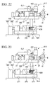
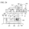
- the ring rolling mill 410 of this embodiment includes a main roll inclining/supporting mechanism which inclines and supports the main roll 11 with respect to the axis of rotation of the mandrel 21 such that the gap between the outer peripheral surface of the mandrel 21 and the outer peripheral surface of the main roll 11 differs on vertical upper side (one side) and on vertical lower side (other side) as seen in a direction along the axis of rotation of the mandrel 21.
- This main roll inclining/supporting mechanism includes a supporting pin 420 (first main roll supporting portion) which rotatably supports the upper end (one end) of the main roll 11 in place, a spherical bearing 430 (second main roll supporting portion) which rotatably supports the lower end (other end) of the main roll 11, and a main roll driving portion 440 (first main roll driving portion) which brings or separates the spherical bearing 430 close to or from the mandrel 21.
- the supporting pin 420 supports the upper end of the main roll 11 so that it can be tilted around a horizontal axis CL7 (axis vertical to the sheet plane of FIG. 22 ) which intersects the axis of the main roll 11 and is twisted with respect to the axis of the mandrel 21.
- the pedestal 370 of this embodiment is provided with wheels 371 which support the pedestal 370 so as to be able to run along one direction. Accordingly, the main roll driving source 350 and the transmission section 360 are integrated with the pedestal 370, and move to the right and left in FIG. 22 .
- the main roll driving portion 440 includes an anchor 441 which is installed in place, and a hydraulic cylinder 442 which is provided between the anchor 441 and the main roll driving source 350.
- the hydraulic cylinder 442 performs extension/retraction operation, the main roll driving portion moves the main roll driving source 350, the transmission section 360, and the pedestal 370 to the right and left in FIG. 22 .
- the main roll 11 can be tilted around the horizontal axis CL7 so that it can be brought close to or separated from the mandrel 21 fixed in place by driving the main roll driving portion 440.
- a ring rolling method using the ring rolling mill 410 of this embodiment having the configuration described above will be described below.
- the main roll 11 is tilted to the right in the figure about the horizontal axis CL7 by driving the main roll driving portion 440 to extend the hydraulic cylinder 442.
- the main roll driving portion 440 By stopping the main roll driving portion 440 in a state where the main roll 11 is inclined at a desired angle in this way, as shown in FIG.
- the mandrel 21 can be inclined and supported with respect to the axis of rotation of the main roll 11 such that the gap between the outer peripheral surface of the mandrel 21 and the outer peripheral surface of the main roll 11 becomes narrower on the lower side (the other side) than on the upper side (one side) as seen in a direction along the axis of rotation of the main roll 11.
- the main roll 11 is tilted to the left in the figure about the horizontal axis CL7 by driving the main roll driving portion 440 to retract the hydraulic cylinder 442.
- the main roll driving portion 440 By stopping the main roll driving portion 440 in a state where the main roll 11 is inclined at a desired angle in this way, as shown in FIG.
- the mandrel 21 can be inclined and supported with respect to the axis of rotation of the main roll 11 such that the gap between the outer peripheral surface of the mandrel 21 and the outer peripheral surface of the main roll 11 becomes narrower on the upper side (the other side) than on the lower side (one side) as seen in a direction along the axis of rotation of the main roll 11.
- the operation in which the mandrel 21 is brought close to or separated from the main roll 11 in a state where the inclining of the main roll 11 is fixed can be performed by driving to advance/retreat the advance/retreat driving cylinder 27, and horizontally moving the whole supporting structure of the mandrel 21 to the right and left in the figure.
- the same operational effects as those of the ring rolling mill 310 of the above fourth embodiment can be obtained. That is, according to the ring rolling mill 410 of this embodiment, the pressing forces applied on the peripheral portion of the ring-shaped body W by the main roll 11 and the mandrel 21 can be made different not only along every peripheral position of the peripheral portion, but along every position in the thickness direction.
- the configuration in which the axial rolls 41 are supported so that they can be rotationally driven around their axes of rotation is shown in the above first embodiment.
- the axial rolls 41 may be rotatably supported, and may rotate as the ring-shaped body W is rotated in its peripheral direction by the main roll 11 and the mandrel 21.
- either the mandrel 21 or the main roll 11 is tilted to the other one.
- the invention is not limited thereto. Both the mandrel 21 and the main roll 11 may be tilted.
- the pressing forces applied on the peripheral portion of the ring-shaped body by the main roll and the mandrel can be made different locally in the peripheral portion of the ring-shaped body.
Landscapes
- Engineering & Computer Science (AREA)
- Mechanical Engineering (AREA)
- Reduction Rolling/Reduction Stand/Operation Of Reduction Machine (AREA)
Applications Claiming Priority (2)
| Application Number | Priority Date | Filing Date | Title |
|---|---|---|---|
| JP2006089750 | 2006-03-29 | ||
| PCT/JP2007/056677 WO2007114174A1 (ja) | 2006-03-29 | 2007-03-28 | リングローリングミルおよびリング圧延方法 |
Publications (3)
| Publication Number | Publication Date |
|---|---|
| EP2000224A1 true EP2000224A1 (de) | 2008-12-10 |
| EP2000224A4 EP2000224A4 (de) | 2017-06-07 |
| EP2000224B1 EP2000224B1 (de) | 2018-08-29 |
Family
ID=38563442
Family Applications (1)
| Application Number | Title | Priority Date | Filing Date |
|---|---|---|---|
| EP07740115.6A Active EP2000224B1 (de) | 2006-03-29 | 2007-03-28 | Ringwalzwerk und ringwalzverfahren |
Country Status (5)
| Country | Link |
|---|---|
| US (2) | US8365564B2 (de) |
| EP (1) | EP2000224B1 (de) |
| JP (1) | JP4702369B2 (de) |
| CN (1) | CN101410193B (de) |
| WO (1) | WO2007114174A1 (de) |
Cited By (1)
| Publication number | Priority date | Publication date | Assignee | Title |
|---|---|---|---|---|
| CN102205384A (zh) * | 2011-04-06 | 2011-10-05 | 沈阳三重机械有限公司 | 异型辗环机 |
Families Citing this family (16)
| Publication number | Priority date | Publication date | Assignee | Title |
|---|---|---|---|---|
| CN102085548B (zh) * | 2010-12-10 | 2012-08-08 | 贵州安大航空锻造有限责任公司 | 钛合金高筒环锻件的辗轧成形方法 |
| US20130125605A1 (en) * | 2011-11-22 | 2013-05-23 | Psm, Inc. | Method of manufacturing door frame for wind tower |
| CN102615222B (zh) * | 2012-03-08 | 2014-06-11 | 江汉大学 | 无缝薄壁环件轧制成形的设备 |
| CN102886474B (zh) * | 2012-11-05 | 2014-12-24 | 济南铸造锻压机械研究所有限公司 | 辗环机径向轧制装置 |
| JP6000874B2 (ja) * | 2012-12-04 | 2016-10-05 | 株式会社神戸製鋼所 | リング素材の圧延方法 |
| CN103978134A (zh) * | 2014-04-30 | 2014-08-13 | 浙江远大重工锻压有限公司 | 球型辗环机芯轴装置 |
| CN103978133B (zh) * | 2014-04-30 | 2016-08-24 | 浙江远大重工锻压有限公司 | 球型辗环机 |
| CN104226868B (zh) * | 2014-09-24 | 2017-01-11 | 武汉理工大学 | 一种球阀阀体复合轧环成形方法 |
| DE102016101939B4 (de) | 2016-02-04 | 2026-01-22 | Sms Group Gmbh | Ringwalzmaschine sowie Verfahren zum Heben und Senken der Dornwalze einer Ringwalzmaschine |
| DE102017008449A1 (de) * | 2017-09-08 | 2019-03-14 | Schuler Pressen Gmbh | Radial-Axial-Ringwalzwerk zum Walzen eines Ringes |
| CN109746358B (zh) * | 2017-11-08 | 2024-03-22 | 上海新宇箴诚电控科技有限公司 | 一种多倍力自对中轧制机 |
| CN108907045B (zh) * | 2018-09-21 | 2024-03-26 | 济南沃茨数控机械有限公司 | 一种轧辊轴向调节机构及辗环机 |
| CN109482790B (zh) * | 2018-11-06 | 2024-02-02 | 佛山市顺德区皇力五金电器有限公司 | 一种可调式五金件轧环设备 |
| CN110280702A (zh) * | 2019-07-25 | 2019-09-27 | 济南沃茨数控机械有限公司 | 多工位辗环机 |
| CN112170747B (zh) * | 2020-09-30 | 2023-06-23 | 贵州安大航空锻造有限责任公司 | 高温合金盆形环锻件辗轧成形方法 |
| CN115121613B (zh) * | 2022-07-05 | 2024-02-13 | 燕山大学 | 一种基于柔性多模块化系统筒节实验轧机装置 |
Family Cites Families (12)
| Publication number | Priority date | Publication date | Assignee | Title |
|---|---|---|---|---|
| US702303A (en) * | 1901-03-30 | 1902-06-10 | Eustace Woolnough Hopkins | Rolling machinery. |
| US1745514A (en) * | 1924-08-26 | 1930-02-04 | Taylor James Hall | Ring-rolling machine |
| US1745614A (en) | 1926-12-02 | 1930-02-04 | Grubb Lee | Vehicle signal switch |
| CH279380A (fr) * | 1949-06-28 | 1951-11-30 | Loewy Engineering Company Limi | Laminoir pour fabriquer des anneaux. |
| DE1188544B (de) * | 1961-12-22 | 1965-03-11 | Wagner & Co Werkzeugmaschinenf | Vierwalzen-Ringwalzwerk mit selbsttaetig nachstellbaren Axialwalzen |
| NL173488C (nl) * | 1981-03-13 | 1984-02-01 | Fontijne Bv Machine | Velgprofileerinrichting. |
| JPS63112009A (ja) * | 1986-10-30 | 1988-05-17 | Kobe Steel Ltd | マンドレル昇降装置を備えたリングミル |
| JP2859446B2 (ja) | 1990-12-03 | 1999-02-17 | 日立金属株式会社 | リングローリングミル |
| JP4229937B2 (ja) | 1996-11-07 | 2009-02-25 | 三井化学株式会社 | 生分解性弾性体 |
| JP2003053466A (ja) | 2001-08-22 | 2003-02-26 | Nippon Spindle Mfg Co Ltd | 輪体のローリング成形装置 |
| CN2724869Y (zh) * | 2004-08-05 | 2005-09-14 | 中信重型机械公司 | 轧制非对称异形环的轧环机专用装置 |
| JP2006055894A (ja) * | 2004-08-23 | 2006-03-02 | Kyoei Seiko Kk | 輪体成形方法およびその装置 |
-
2007
- 2007-03-28 JP JP2007535935A patent/JP4702369B2/ja active Active
- 2007-03-28 WO PCT/JP2007/056677 patent/WO2007114174A1/ja not_active Ceased
- 2007-03-28 EP EP07740115.6A patent/EP2000224B1/de active Active
- 2007-03-28 US US12/294,533 patent/US8365564B2/en active Active
- 2007-03-28 CN CN2007800108989A patent/CN101410193B/zh active Active
-
2012
- 2012-12-27 US US13/727,990 patent/US8689597B2/en active Active
Non-Patent Citations (1)
| Title |
|---|
| See references of WO2007114174A1 * |
Cited By (2)
| Publication number | Priority date | Publication date | Assignee | Title |
|---|---|---|---|---|
| CN102205384A (zh) * | 2011-04-06 | 2011-10-05 | 沈阳三重机械有限公司 | 异型辗环机 |
| CN102205384B (zh) * | 2011-04-06 | 2012-11-14 | 沈阳三重机械有限公司 | 异型辗环机 |
Also Published As
| Publication number | Publication date |
|---|---|
| US20100236311A1 (en) | 2010-09-23 |
| WO2007114174A1 (ja) | 2007-10-11 |
| CN101410193A (zh) | 2009-04-15 |
| CN101410193B (zh) | 2011-02-09 |
| JP4702369B2 (ja) | 2011-06-15 |
| EP2000224A4 (de) | 2017-06-07 |
| EP2000224B1 (de) | 2018-08-29 |
| US8365564B2 (en) | 2013-02-05 |
| US8689597B2 (en) | 2014-04-08 |
| JPWO2007114174A1 (ja) | 2009-08-13 |
| US20130180302A1 (en) | 2013-07-18 |
Similar Documents
| Publication | Publication Date | Title |
|---|---|---|
| EP2000224B1 (de) | Ringwalzwerk und ringwalzverfahren | |
| CN102172765A (zh) | 轴承外环的制造方法 | |
| JP2000302383A (ja) | パンタグラフ式ジャッキ及びその製造方法 | |
| JP6130832B2 (ja) | 圧延機のためのロールホールダカートリッジ | |
| CN113751606A (zh) | 一种厚壁金属直缝焊管连续渐进式扩径整圆装置及方法 | |
| JPWO1999019093A1 (ja) | 穿孔圧延機 | |
| CN220479720U (zh) | 一种超细管斜轧穿孔高刚度抱芯装置 | |
| CN101450350B (zh) | 用于制造无缝钢管的方法和轧机 | |
| JP2003126916A (ja) | 螺旋溝付管の製造方法およびその製造装置 | |
| CN109590416B (zh) | 一种联动式三辊斜轧机 | |
| JP3463568B2 (ja) | トラニオンの製造方法 | |
| CN115740010A (zh) | 一种穿孔变形补偿式钢管轧制机及使用方法 | |
| RU2189286C2 (ru) | Многофункциональная клеть прокатного стана для прокатки двутавровой широкополочной балки и способ прокатки двутавровой широкополочной балки с помощью многофункциональной клети прокатного стана | |
| JPH09192749A (ja) | パイプミルにおけるブレークダウン用ロール装置 | |
| EP2418029B1 (de) | Stanz- und walzverfahren und vorrichtung zu dessen implementierung | |
| JP2006142364A (ja) | カシメ装置 | |
| RU2304033C1 (ru) | Способ получения буртов на трубчатых заготовках раскаткой | |
| CN120480082A (zh) | 一种盾构机刀圈碾环装置 | |
| CN102281960B (zh) | 用于滚轧机的轧辊 | |
| SU1346301A1 (ru) | Инструмент дл раскатки трубчатых заготовок | |
| JP2001191111A (ja) | 異形管のインライン製造方法及び製造装置 | |
| CN103350169A (zh) | 一种轮辋滚型机主轴倾斜角度调整机构 | |
| JP2007130649A (ja) | ワークロールシフト圧延機のスピンドル装置 | |
| JPH08197109A (ja) | 圧延機 | |
| JP3226590B2 (ja) | ケーンミルのトップロール圧搾駆動装置 |
Legal Events
| Date | Code | Title | Description |
|---|---|---|---|
| PUAI | Public reference made under article 153(3) epc to a published international application that has entered the european phase |
Free format text: ORIGINAL CODE: 0009012 |
|
| 17P | Request for examination filed |
Effective date: 20080926 |
|
| AK | Designated contracting states |
Kind code of ref document: A1 Designated state(s): DE FR GB IT |
|
| DAX | Request for extension of the european patent (deleted) | ||
| RBV | Designated contracting states (corrected) |
Designated state(s): DE FR GB IT |
|
| RAP1 | Party data changed (applicant data changed or rights of an application transferred) |
Owner name: HITACHI METALS MMC SUPERALLOY, LTD. |
|
| RAP1 | Party data changed (applicant data changed or rights of an application transferred) |
Owner name: HITACHI METALS MMC SUPERALLOY, LTD. |
|
| RA4 | Supplementary search report drawn up and despatched (corrected) |
Effective date: 20170508 |
|
| RIC1 | Information provided on ipc code assigned before grant |
Ipc: B21H 1/06 20060101ALI20170428BHEP Ipc: B21B 5/00 20060101AFI20170428BHEP |
|
| GRAP | Despatch of communication of intention to grant a patent |
Free format text: ORIGINAL CODE: EPIDOSNIGR1 |
|
| STAA | Information on the status of an ep patent application or granted ep patent |
Free format text: STATUS: GRANT OF PATENT IS INTENDED |
|
| INTG | Intention to grant announced |
Effective date: 20180420 |
|
| GRAS | Grant fee paid |
Free format text: ORIGINAL CODE: EPIDOSNIGR3 |
|
| GRAA | (expected) grant |
Free format text: ORIGINAL CODE: 0009210 |
|
| STAA | Information on the status of an ep patent application or granted ep patent |
Free format text: STATUS: THE PATENT HAS BEEN GRANTED |
|
| RAP1 | Party data changed (applicant data changed or rights of an application transferred) |
Owner name: HITACHI METALS, LTD. |
|
| AK | Designated contracting states |
Kind code of ref document: B1 Designated state(s): DE FR GB IT |
|
| REG | Reference to a national code |
Ref country code: GB Ref legal event code: FG4D |
|
| REG | Reference to a national code |
Ref country code: DE Ref legal event code: R096 Ref document number: 602007055939 Country of ref document: DE |
|
| REG | Reference to a national code |
Ref country code: DE Ref legal event code: R097 Ref document number: 602007055939 Country of ref document: DE |
|
| PLBE | No opposition filed within time limit |
Free format text: ORIGINAL CODE: 0009261 |
|
| STAA | Information on the status of an ep patent application or granted ep patent |
Free format text: STATUS: NO OPPOSITION FILED WITHIN TIME LIMIT |
|
| 26N | No opposition filed |
Effective date: 20190531 |
|
| PGFP | Annual fee paid to national office [announced via postgrant information from national office to epo] |
Ref country code: GB Payment date: 20260209 Year of fee payment: 20 |
|
| PGFP | Annual fee paid to national office [announced via postgrant information from national office to epo] |
Ref country code: DE Payment date: 20260204 Year of fee payment: 20 |
|
| PGFP | Annual fee paid to national office [announced via postgrant information from national office to epo] |
Ref country code: IT Payment date: 20260220 Year of fee payment: 20 |
|
| PGFP | Annual fee paid to national office [announced via postgrant information from national office to epo] |
Ref country code: FR Payment date: 20260209 Year of fee payment: 20 |