US1745514A - Ring-rolling machine - Google Patents
Ring-rolling machine Download PDFInfo
- Publication number
- US1745514A US1745514A US734182A US73418224A US1745514A US 1745514 A US1745514 A US 1745514A US 734182 A US734182 A US 734182A US 73418224 A US73418224 A US 73418224A US 1745514 A US1745514 A US 1745514A
- Authority
- US
- United States
- Prior art keywords
- roll
- ring
- rolling
- bearing
- engaging
- Prior art date
- Legal status (The legal status is an assumption and is not a legal conclusion. Google has not performed a legal analysis and makes no representation as to the accuracy of the status listed.)
- Expired - Lifetime
Links
- 238000005096 rolling process Methods 0.000 title description 52
- 230000006835 compression Effects 0.000 description 5
- 238000007906 compression Methods 0.000 description 5
- 230000002829 reductive effect Effects 0.000 description 4
- 239000012530 fluid Substances 0.000 description 2
- 230000000717 retained effect Effects 0.000 description 2
- 101710083262 Ectin Proteins 0.000 description 1
- 241001658031 Eris Species 0.000 description 1
- 102000011842 Serrate-Jagged Proteins Human genes 0.000 description 1
- 108010036039 Serrate-Jagged Proteins Proteins 0.000 description 1
- 230000000570 adjustive effect Effects 0.000 description 1
- 238000004873 anchoring Methods 0.000 description 1
- 238000010276 construction Methods 0.000 description 1
- 230000003247 decreasing effect Effects 0.000 description 1
- 230000000266 injurious effect Effects 0.000 description 1
- 230000000670 limiting effect Effects 0.000 description 1
- 238000006467 substitution reaction Methods 0.000 description 1
Images


Classifications
-
- B—PERFORMING OPERATIONS; TRANSPORTING
- B21—MECHANICAL METAL-WORKING WITHOUT ESSENTIALLY REMOVING MATERIAL; PUNCHING METAL
- B21H—MAKING PARTICULAR METAL OBJECTS BY ROLLING, e.g. SCREWS, WHEELS, RINGS, BARRELS, BALLS
- B21H1/00—Making articles shaped as bodies of revolution
- B21H1/06—Making articles shaped as bodies of revolution rings of restricted axial length
-
- Y—GENERAL TAGGING OF NEW TECHNOLOGICAL DEVELOPMENTS; GENERAL TAGGING OF CROSS-SECTIONAL TECHNOLOGIES SPANNING OVER SEVERAL SECTIONS OF THE IPC; TECHNICAL SUBJECTS COVERED BY FORMER USPC CROSS-REFERENCE ART COLLECTIONS [XRACs] AND DIGESTS
- Y10—TECHNICAL SUBJECTS COVERED BY FORMER USPC
- Y10S—TECHNICAL SUBJECTS COVERED BY FORMER USPC CROSS-REFERENCE ART COLLECTIONS [XRACs] AND DIGESTS
- Y10S118/00—Coating apparatus
- Y10S118/14—Roller, conical
Definitions
- This invention relates to a ring rolling mill or machine of the type in which aring is reduced and finished to proper size and form.
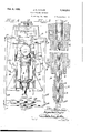
- Figure 1 is a vertical sectional view of a ring rolling mill involving this invention.
- Figure '2 is an enlarged fragmentary elevational view of the rollers for rolling a ring with a groove.
- Figure 3 is an enlarged fragmentary ole-- rational view of a set of rolls for rolling a ring with a flange or head.
- Figure 4 is an enlarged elevational View taken uponthe line 4-4 of Figure Llooking in the direction of the arrows.
- Figure Er is an enlarged sectional view upon the line'5-5 of Figure 1.
- Figure (3 is an enlarged top plan View of the machine with parts in section.
- Figure 7 is an enlarged sectional view upon the line 7T of Figure 1 looking in the direction of the arrows.
- Figure 8 is an enlarged sectional view upon the line 8-8 of Figure 1 showing parts in elevation.
- Figure 9 is an enlarged sectional view through the fringe removing mechanism.
- Figure 1D is an enlarged plan view of the fringe removing mechanism.
- Figure 11 is an enlarged end elevational and part sectional view of the fringe removing mechanism.
- the machine or rolling mill comprises a rigid and stationary frame 1 and a longitudinally adjustable carriage or frame 2 upon which a ve'rtically adjustable bearing 3 is supported.
- the frame 1 is provided with a hollow bearing 4 having an axis which is inclined with respect to the plane through which the ring travels.
- a hollow spindle 5 is journalled in this bearing as shown more clearly in Figure 5, and a roller 6 integral with the spindle projects beyond the bearing and is adapted for engaging one side of the ring to be rolled.
- a thrust bearing 7 is preferably interposed between the upper end of the bearing and the roll 6 which is bevelled downwardly from the center upon its end or outer periphery. The journal of this roll extends below the bearing 4 for the reception of a bevel gear 8 which is splined thereon and retained by a nut 9.
- a hollow or tubular mem ber 10 is slidably splined within the bore of the spindle 5 and terminates a suitable dis tance from the roll head 6 to leave a space for a roll 11 having an upper outwaidly flaring head 11 the flare of which compensates for the inclination of the axis of the 35 roll 5.
- the head ll has a bevelled top for a purpose that will later appear.
- the head 11 projects above the end of the roll 6 and is adapted for rolling the inner periphery of the ring. The height of such head 11 determines the thickness of the ring.
- the lower end of the roll 11 is removably connected to the member 10 by a rod 12.
- the memberlO projects below the lower end of the bearing 4 and a rod 12 extends therethrough. Its inner end is threaded into the lower end of the hub of the roll 11 for retaining the same. By unscrewing this rod, the roll 11 may be easily withdrawn and anew or different roll substituted therefor.
- a A cross head 13 is attached to the lower part of the member 10.
- this cross head has an opening for receiving the member 10 and nuts 14 are adapted to clamp the said cross head thereon.
- the ends of the cross head are in the form of trunnions 16 upon which the lower ends of links 15 are pivotally attached. The upper ends of these links are pivoted upon trunnions 16 which constitute the terminals of a cross head i 17 or the like attached to the adjustable bearin 3.
- the cross heads and links 15 form a yo e or pivotal connection between the bearing 3 and the member 10 whereby the roll 11 is caused to partake of the adjustment of the bearing 3/
- the roll.11 cannot enter the axial bore of the roll 6 any further than the line between the flaring head and cylindrical body portion as shown in Figure 5.
- the roll 11 In rolling a ring that is to be reduced the roll 11 will of course be elevated above the position shown in Figure 5.
- the inner periphery of the ring will hence be bevelled at first according to the contour of the roll 11. This, however, will be later rectified.
- the longitudinally adjustable housing 2 is provided with a pair of depending parallel grooved members 18 ( Figure 4) which engage gibs19, projecting from the lateral sides of the frame 1.
- the frame 2 extends above the bearing 3 where it is provided with a suitable cross piece 20 having a socket in which a screw shaft 21 is rotatably anchored.
- the screw shaft has a bearing collar 22 on each side of the cross piece 20 for rotatably anchoring the same; the lower end of the screw being threaded in the bearing 3 which is slidably mounted in grooves 3 ( Figure 8) of the end of the frame 2.
- a worm gear 23 is screwed upon the upper end of the shaft 21 and is adapted to be driven by a worm 24 on the shaft of a motor 25 supported upon a suitable platform on the top of the frame 2.
- the bearing 3 is hence adjustive through the operation of the motor.
- a shaft 26 is journalled in the bearing 3 at an inclination to the plane of the ring to be rolled.
- the lower ends of the shaft 26 has a frusto-conical or tapered roll 27 which is adapted for engaging the other side of the ring to be rolled.
- a frusto-conical or tapered roll 27 which is adapted for engaging the other side of the ring to be rolled.
- the roll 27 will not have much more than a line contact with the ring so no injurious abradant action will occur and no cross cutting will occur.
- a fourth roll 28 which is cylindrical and suitably journalled in a bifurcation formed in the support or carriage2 is adapted for engaging and rolling the outer periphery of the ring.
- This roll is driven by a pair of frictlon drums 29 supported upon suitable shafts upon the upper end of the shaft 33 and meshes with a gear 35 on the outer end of the shaft 26 for rotating the roll 27.
- a bevelled gear 36 is secured upon the lower end of the shaft 33 and meshes with a bevelled gear 37 secured upon ashort shaft 38 journalled in a bracket 39 on the movable carriage2.
- a spur gear 40 is secured upon the stub shaft 38 and meshes with a gear 41 upon the shaft 42 of a motor 43 which rests upon a suitable platform integral with the carriage-2.
- This carriage has a depending lug 44 in which a shaft 45 is threaded.
- the end of the shaft opposite the threads is rotatably anchored in an upstanding lug 46 on the stationary frame 1.
- a worm gear 47 is secured upon the screw shaft 45.
- This worm gear meshes with a worm 48 secured upon the shaft of a motor 49 which is supported upon a bracket 50 extending from the stationary frame 1.
- a shaft 51 is journalled in the lower part of the stationary frame and projects therebeyond to form an attaching means for a suitable source of power (not shown).
- the inner end of this shaft supports a bevel gear 52 which drives the aforementioned bevel gear 8 for rotating the roll 6.
- the rolls 6, 11, 27 and 28 form substantially a closed way or pass through which the rings are rolled.
- I have illustrated a ring 53 the rolls.
- the ring is also supported by a pair of opposed rolls 54 and 55 shown in Figures 1 and 9, and a pair of guide rolls 56 ( Figure 6) mounted upon a ring platform 57 which is slidably mounted upon a bench 58 by a lateral tongue and groove connection on each side.
- the front part of the platform is shown as bifurcated, the rear portion, however, is in the form of a slideway 59 ( Figure 11) in which the base of a frame 60 is slidably mounted.
- This frame is retained in position by a pair of overhanging cleats 61 which engage over pro ectin shoulders on the frame.
- a groove 62 extents along the central longitudinal.
- a second frame 68 is slidingly supported by tongue and groove connections for longitudinal movement in the upper part of the frame 60 and is adapted to project therebeyond.
- the forward end of this frame has a groove or opening in which a head 69 is slida-bly mounted for vertical movement by a tongue and groove connection.
- This head has aninclined outer end upon which the roll 55 is rotatably mounted by means of a Stud 70. This roll is adapted to engage the upper inner corner of the ring.
- a fluid compression cylinder-71 is mounted upon the frame 68 just above the head 69.
- the piston in this cylinder is provided with a rod or stem 72 that is threaded in the vertically movable head 69.
- the compression in the cylinder 71 is such that the roll 55 will nor mally be pressed against the ring 53.
- the rear cross piece 73 of the frame 60 supports afluid compression cylinder 74, the piston of which is provided with a stem 75 that extends through an aperture in the cross piece 73 and that is threaded in the'longitudinally movable frame 68.
- the compression in the cylinder 74 issuch as to draw the frame 68 rearwardly to maintain the roll 55 in proper longitudinal position against the ring 53. As the compressed fluid is more or less elastic, it will be evident that the fringe removin rolls 54 and 55 will be yieldingly maintaine against the ring 53.
- the roll 6 has'its axis within the ring 53, consequently it will rotate in the same direction as the ring 53 rotates.
- the roll 27 will also rotate in the proper direcsuch that true rolling action occurs at the initial stages of rolling a certain sized ring.
- the liability to serrate the sides of the ring will be greatly decreased.
- the flared roll 11 which is connected with the adjustable bearin 3 partakes of the adjustment of the roll 27, so as to always close the gap between therolls 6 and 27.
- the flaring roll In the initial stage of rolling a ring, that is to be reduced, the flaring roll will of course be above the position shown in Figure 1, consequently the inner periphery of the ring may first have a bevel to fit the contour of the raised flaring roll. But this will later be rectified as the roll 11 is gradually adjusted to its finishing position.
- the roll 11 may therefore be said to be automatically adjustable with the roll 27 for varying the size of the ring pass.
- an upper conical roll, a lower roll havin an inclined axis and an upper bevelled sur ace, a roll removably and concentrically mounted within the lower roll, and having a flaring head to compensate for the inclination of its axis, and a horizontal roll cooperating with said aforementioned rolls for defining a pass for receiving having its axis at an inclination to said ring and cooperating with said first roll, an inner roll projecting centrally of said second roll, and mechanism connecting said bearing and inner roll.
- a stationary bearing In a ring rolling mill, a stationary bearing, a hollow roll journalled in said bearing, a second roll secured in said hollow roll and projecting therebe'yond, an adjustable hearing, a frusto-conical roll journalled therein and adapted for cooperation with said other rolls, and mechanism connecting said adjustable bearing and second roll for conjoint movement.
- a stationary bearing having an inclined axial bore, a hollow roll having a journal fitting said bore, a slidable member splincd in said hollow roll, a roll having a flaring head removably clutched to said member, an adjustable bearing, a roll journalled therein, a connection between said adjustable bearing and member; and an exterior roll cooperating with said other rolls for defining a pass.
- a plurality of rolling elements dfining a pass comprising a ta pered roll and a flaring roll renmvably supported in one of said rolls, said last mentioned roll having an inclination to the ring to be rolled.
- a tapered roll adapted for rolling a side of the ring, a roll having an inclined axis and a bevelled end for engaging the opposite side of the ring, and rolls for engaging the inner and outer peripheries of the ring.
- a frusto-conical roll for engaging one side of the ring, a roll havinga bevelled surface for-engaging the other side of the ring.
- said last mentioned roll having an axis inclined with respect to the plane of the ring, and a flaring roll re movably carried co-axially with said last mentioned roll.
- a frusto-conical roll having an inclined axis with respect to the plane of the ring for engaging one side thereof, a roll having a tapered end for engaging the other side-0f the ring and having an axis inclined with respect to the ring and extending within said ring.
- a flaring roll coaxial with said tapered roll for engaging the inner periphery of'the ring, and an independent roll for engaging the outer periphery of the ring.
- a bearing In a ring rolling mill, a bearing, a roll carried thereby having an axis inclined with respect to the plane of the ring, a flaring roll mounted coaxially of said roll., a second bearing. a frusto-conical roll carried thereby, and a cylindrical roll also carried by said second bearing. said rolls defining an enclosed ring pass and one of said bearings being adjustable relative to the other.
- an adjustable bearing a roll carried thereby for rolling one side of the ring, a roll having a tapered end for engaging the other side of the ring.
- a slidable flaring roll mounted co-axially of said tapered roll. a pivotal connection between said adjustable bearing and flaring roll, and a cylindrical roll cooperating with said other rolls for forming a ring pass.
- an adjustable bearing rolls carried thereby, a stationary bearing. a roll carried thereby, a flaring roll slidably mounted in said second roll, a mem ber extending into said second roll clutched to said flaring roll, and a yoke pivotally connecting said member and adjustable bearing for conjoint movement.
- the combination with mechanism for rolling the ring,of means for removing fringesfrom the: ring comprising elements having grooves for engaging the corners of the ring, and means for yield-f ingly pressing the same against the ring.
- the combination with mechanism for rolling the ring, of mechanism for removing fringes from the ring comprising a roll for engaging a corner of thering, a second roll for engaging an opposite corner of the r1ng, and y elding means for urging one roll in one direction and simu'l taneously urging the other roll intwo directions for the purpose set forth.
- a frusto-conical roll for engaginga side of the ring, a second roll having a tapered end for rolling the other side of the ring, a third roll having a flared upper portion equal to the thickness of the finished ring for rolling the inner periphery thereof, said third roll adjustably telescoping co-axially of said second roll.
- an adjustable frusto-conical roll for rolling one side of the ring, a tapered roll for engaging the other side of the ring, 'a third roll mounted coaxially of said tapered roll and having an upper flaring portion substantially equal to the thickness of the finished ring for rolling the inner periphery thereof. and a connection between said conical roll and third roll whereby said third roll will be automatically adjusted with the adjustment of said'conical roll.
- an adjustable frusto-conical roll for engaging one side of the ring.
- a tapered ended roll having an axis inclined to the plane of the ring for engaging ments and presenting a different contour during its shifting movements.
- a plurality of rolling elements defining substantially a closed ring pass, one of said elements com prising a roll having an upper fiarin g portion inclined to the plane of the ring, and means for adjusting said roll to bring said flaring portion into action for finishing said ring.
- a conical roll having a stepped surface for engaging. one side of the ring, an opposed roll having an inclined axis and a bevelled end for engaging the opposite side of the ring, and a roll 00- axial with the last mentioned roll for engaging a periphery of the ring.
- a plurality of rolls defining a pass one of said rolls having a bevelled top and another roll having a conicalcontour engaging said bevelled top.
Landscapes
- Engineering & Computer Science (AREA)
- Mechanical Engineering (AREA)
- Reduction Rolling/Reduction Stand/Operation Of Reduction Machine (AREA)
Description
Feb. 4, 1930. J. H. TAYLOR RING ROLLING MACHINE Filed Aug. 26, 1924- 4 Sheets-Sheet 1 \/E :13 James Hall Taylaf Fgb. 4, 1930. J. H. TAYLOR 1,745,514
RING ROLLING MACHINE Filed Aug. 26, 1924 4 Sheets-Sheet 2 IEWN JamesHallTaylov Feb. 4, 1930. J. H. TAYLOR RING ROLLING MACHINE Filed Aug. 26, 1924 4 Sheets-Sheet 5 lug . V v James/1a]? Taylm" Feb. 4, 1930. H, TAYLOR 1,745,514
RING ROLLING MACHINE Filed Aug. 26, 1924 4 Sheets-Sheet 4 .mfi V I VEDlElE\' James Hall Ta lor Patented Feb. 4, 1930 PATENT OFFICE JAMES HALL TAYLOR, OF OAK PARK, ILLINOIS RING-ROLLING MACHINE Application filed August 26, 1924-. Serial No. 734,182.
This invention relates to a ring rolling mill or machine of the type in which aring is reduced and finished to proper size and form.
It is an object of this invention to provide a ring rolling mill which is more readily adjustable for rolling rings of any eonvenient size or form, either with a flange or a groove or without either, in which the substitution of ditterent rolls can be readily effected, in
which means. are provided for eliminating fringes on the rings, and-in which the rolls are so designed and arranged thattheir action will always tend to rotate the ring without undue friction and slippage, or cross cutting.
\Vith these and other objects in view which will become more apparent in the following description and disclosures, this invention comprises the novel structure and combina- 2 tions hereinafter described and more particularly pointed out and defined in the appended claims. In the accompanying drawings which illustrate a preferred embodiment of this invention and in which similar reference numerals refer to similar features in the different views:
Figure 1 is a vertical sectional view of a ring rolling mill involving this invention.
Figure '2 is an enlarged fragmentary elevational view of the rollers for rolling a ring with a groove.
Figure 3 is an enlarged fragmentary ole-- rational view of a set of rolls for rolling a ring with a flange or head.
Figure 4 is an enlarged elevational View taken uponthe line 4-4 of Figure Llooking in the direction of the arrows.
Figure Eris an enlarged sectional view upon the line'5-5 of Figure 1.
Figure (3 is an enlarged top plan View of the machine with parts in section.
Figure 7 is an enlarged sectional view upon the line 7T of Figure 1 looking in the direction of the arrows.
Figure 8 is an enlarged sectional view upon the line 8-8 of Figure 1 showing parts in elevation.
Figure 9 is an enlarged sectional view through the fringe removing mechanism.
Figure 1D is an enlarged plan view of the fringe removing mechanism.
Figure 11 is an enlarged end elevational and part sectional view of the fringe removing mechanism.
As shown on the drawings:
Referring now to the drawings which illustrate one embodiment of this invention, it will be noted that the machine or rolling mill comprises a rigid and stationary frame 1 and a longitudinally adjustable carriage or frame 2 upon which a ve'rtically adjustable bearing 3 is supported.
.The frame 1 is provided with a hollow bearing 4 having an axis which is inclined with respect to the plane through which the ring travels. A hollow spindle 5 is journalled in this bearing as shown more clearly in Figure 5, and a roller 6 integral with the spindle projects beyond the bearing and is adapted for engaging one side of the ring to be rolled. A thrust bearing 7 is preferably interposed between the upper end of the bearing and the roll 6 which is bevelled downwardly from the center upon its end or outer periphery. The journal of this roll extends below the bearing 4 for the reception of a bevel gear 8 which is splined thereon and retained by a nut 9. A hollow or tubular mem ber 10 is slidably splined within the bore of the spindle 5 and terminates a suitable dis tance from the roll head 6 to leave a space for a roll 11 having an upper outwaidly flaring head 11 the flare of which compensates for the inclination of the axis of the 35 roll 5. The head ll has a bevelled top for a purpose that will later appear. The head 11 projects above the end of the roll 6 and is adapted for rolling the inner periphery of the ring. The height of such head 11 determines the thickness of the ring. The lower end of the roll 11 is removably connected to the member 10 by a rod 12. The memberlO projects below the lower end of the bearing 4 and a rod 12 extends therethrough. Its inner end is threaded into the lower end of the hub of the roll 11 for retaining the same. By unscrewing this rod, the roll 11 may be easily withdrawn and anew or different roll substituted therefor.
a A cross head 13 is attached to the lower part of the member 10. In the present instance, this cross head has an opening for receiving the member 10 and nuts 14 are adapted to clamp the said cross head thereon. The ends of the cross head are in the form of trunnions 16 upon which the lower ends of links 15 are pivotally attached. The upper ends of these links are pivoted upon trunnions 16 which constitute the terminals of a cross head i 17 or the like attached to the adjustable bearin 3. The cross heads and links 15 form a yo e or pivotal connection between the bearing 3 and the member 10 whereby the roll 11 is caused to partake of the adjustment of the bearing 3/ The roll.11, however, cannot enter the axial bore of the roll 6 any further than the line between the flaring head and cylindrical body portion as shown in Figure 5. In rolling a ring that is to be reduced the roll 11 will of course be elevated above the position shown in Figure 5. The inner periphery of the ring will hence be bevelled at first according to the contour of the roll 11. This, however, will be later rectified. The longitudinally adjustable housing 2 is provided with a pair of depending parallel grooved members 18 (Figure 4) which engage gibs19, projecting from the lateral sides of the frame 1. In referring to Figure 1, it will be observed that the frame 2 extends above the bearing 3 where it is provided with a suitable cross piece 20 having a socket in which a screw shaft 21 is rotatably anchored. The screw shaft has a bearing collar 22 on each side of the cross piece 20 for rotatably anchoring the same; the lower end of the screw being threaded in the bearing 3 which is slidably mounted in grooves 3 (Figure 8) of the end of the frame 2. A worm gear 23 is screwed upon the upper end of the shaft 21 and is adapted to be driven by a worm 24 on the shaft of a motor 25 supported upon a suitable platform on the top of the frame 2. The bearing 3 is hence adjustive through the operation of the motor.
A shaft 26 is journalled in the bearing 3 at an inclination to the plane of the ring to be rolled. The lower ends of the shaft 26 has a frusto-conical or tapered roll 27 which is adapted for engaging the other side of the ring to be rolled. On account of the conical feature of this roll and the inclination thereof which extends substantially in a line through the center of the ring to be rolled there will be little tendency for slippage or friction between it and the ring that is being rolled. Further, the roll 27 will not have much more than a line contact with the ring so no injurious abradant action will occur and no cross cutting will occur.
A fourth roll 28 which is cylindrical and suitably journalled in a bifurcation formed in the support or carriage2 is adapted for engaging and rolling the outer periphery of the ring. This roll is driven by a pair of frictlon drums 29 supported upon suitable shafts upon the upper end of the shaft 33 and meshes with a gear 35 on the outer end of the shaft 26 for rotating the roll 27. A bevelled gear 36 is secured upon the lower end of the shaft 33 and meshes with a bevelled gear 37 secured upon ashort shaft 38 journalled in a bracket 39 on the movable carriage2. A spur gear 40 is secured upon the stub shaft 38 and meshes with a gear 41 upon the shaft 42 of a motor 43 which rests upon a suitable platform integral with the carriage-2. This carriage has a depending lug 44 in which a shaft 45 is threaded. The end of the shaft opposite the threads is rotatably anchored in an upstanding lug 46 on the stationary frame 1. A worm gear 47 is secured upon the screw shaft 45. This worm gear meshes with a worm 48 secured upon the shaft of a motor 49 which is supported upon a bracket 50 extending from the stationary frame 1. A shaft 51 is journalled in the lower part of the stationary frame and projects therebeyond to form an attaching means for a suitable source of power (not shown). The inner end of this shaft supports a bevel gear 52 which drives the aforementioned bevel gear 8 for rotating the roll 6.
In referring to Figure 1, it will be noted that the rolls 6, 11, 27 and 28 form substantially a closed way or pass through which the rings are rolled. In the present instance, I have illustrated a ring 53 the rolls. In addition to the support that is afforded by the pass of the rolls, the ring is also supported by a pair of opposed rolls 54 and 55 shown in Figures 1 and 9, and a pair of guide rolls 56 (Figure 6) mounted upon a ring platform 57 which is slidably mounted upon a bench 58 by a lateral tongue and groove connection on each side. The front part of the platform is shown as bifurcated, the rear portion, however, is in the form of a slideway 59 (Figure 11) in which the base of a frame 60 is slidably mounted.
This frame is retained in position by a pair of overhanging cleats 61 which engage over pro ectin shoulders on the frame. A groove 62 extents along the central longitudinal.
assing through portion of the frame; a slide 63 is mounted.
in this groove, and is provided at its forward end with a head 64 having a rearwardly inclined surface upon which the roll 54 is journalled by means of a stud An air cylinder 66 is attached to the forward end of the platform 57 which is provided with a suitable upstanding flange 58. for this purpose. The piston in the cylinder has a rod orstem 67 that is threaded into the slide 63. It will be noted that the roll 54 is provided with a groove that fits the corner of the ring. The compression in the cylinder 66 is such that theslide 63 will be yieldingly drawn to the right in Figure 9 to mainta n the roll 54 against the ring.
A second frame 68 is slidingly supported by tongue and groove connections for longitudinal movement in the upper part of the frame 60 and is adapted to project therebeyond. The forward end of this frame has a groove or opening in which a head 69 is slida-bly mounted for vertical movement by a tongue and groove connection. -This head has aninclined outer end upon which the roll 55 is rotatably mounted by means of a Stud 70. This roll is adapted to engage the upper inner corner of the ring. A fluid compression cylinder-71 is mounted upon the frame 68 just above the head 69. The piston in this cylinder is provided with a rod or stem 72 that is threaded in the vertically movable head 69. The compression in the cylinder 71 is such that the roll 55 will nor mally be pressed against the ring 53. The rear cross piece 73 of the frame 60 supports afluid compression cylinder 74, the piston of which is provided with a stem 75 that extends through an aperture in the cross piece 73 and that is threaded in the'longitudinally movable frame 68. The compression in the cylinder 74 issuch as to draw the frame 68 rearwardly to maintain the roll 55 in proper longitudinal position against the ring 53. As the compressed fluid is more or less elastic, it will be evident that the fringe removin rolls 54 and 55 will be yieldingly maintaine against the ring 53.
In Figure 2, I have shown a ring pass I formed by the rolls 6, 27 and 28 and a modified form offlaring roll 11 which is provided with a rib 11 for rolling a groove in the inner eriphery of the ring.
In igure 3,.there is shown a pass formed by the rolls 6, 11 and 28 and a modified roll 27 having an outer stepped or reduced portion 27 b for rolling a ring with a head or rib on one. side. It will therefore be. readily apparent that" the roll '11 or 27 may be replaced by a different roll as desired. It is evident thatas the roll 27 is raised the'flaring roll 11 will be correspondingly raised and ma easily be removed when the carriage 2 is shifted rearwardly. This flaring roll has an upper bevelled surface to afford a rollin surface for the frusto-conieal roll 27 should the same contact therewith,
In referring to the drawin it will be noted that the roll 6 has'its axis within the ring 53, consequently it will rotate in the same direction as the ring 53 rotates. The roll 27 will also rotate in the proper direcsuch that true rolling action occurs at the initial stages of rolling a certain sized ring. As the roll 27 always tends to rotate the ring and does not cut transversely of the ring, the liability to serrate the sides of the ring will be greatly decreased. It should also be noted that the flared roll 11 which is connected with the adjustable bearin 3 partakes of the adjustment of the roll 27, so as to always close the gap between therolls 6 and 27. In the initial stage of rolling a ring, that is to be reduced, the flaring roll will of course be above the position shown in Figure 1, consequently the inner periphery of the ring may first have a bevel to fit the contour of the raised flaring roll. But this will later be rectified as the roll 11 is gradually adjusted to its finishing position. The roll 11 may therefore be said to be automatically adjustable with the roll 27 for varying the size of the ring pass.
I am aware that many changes may be made, and numerous details of construction may be varied through a wide range without departing from the principles of this invention, and I therefore do not purpose limiting the patent granted hereon, otherwise than necessitated byv the prior art.
I claim as my, invention 1. In a ring rolling mill, an upper conical roll, a lower roll havin an inclined axis and an upper bevelled sur ace, a roll removably and concentrically mounted within the lower roll, and having a flaring head to compensate for the inclination of its axis, and a horizontal roll cooperating with said aforementioned rolls for defining a pass for receiving having its axis at an inclination to said ring and cooperating with said first roll, an inner roll projecting centrally of said second roll, and mechanism connecting said bearing and inner roll.
4. In a ring rolling mill, a stationary bearing, a hollow roll journalled in said bearing, a second roll secured in said hollow roll and projecting therebe'yond, an adjustable hearing, a frusto-conical roll journalled therein and adapted for cooperation with said other rolls, and mechanism connecting said adjustable bearing and second roll for conjoint movement.
5. In a rolling mill, a stationary bearing having an inclined axial bore, a hollow roll having a journal fitting said bore, a slidable member splincd in said hollow roll, a roll having a flaring head removably clutched to said member, an adjustable bearing, a roll journalled therein, a connection between said adjustable bearing and member; and an exterior roll cooperating with said other rolls for defining a pass. a
6. In a rolling mill, a plurality of rolling elements dfining a pass comprising a ta pered roll and a flaring roll renmvably supported in one of said rolls, said last mentioned roll having an inclination to the ring to be rolled.
7. In a ring rolling mill. a tapered roll adapted for rolling a side of the ring, a roll having an inclined axis and a bevelled end for engaging the opposite side of the ring, and rolls for engaging the inner and outer peripheries of the ring.
8. In a ring rolling mill, a frusto-conical rollfor engaging one side of the ring, a roll havinga bevelled surface for-engaging the other side of the ring. said last mentioned roll having an axis inclined with respect to the plane of the ring, and a flaring roll re movably carried co-axially with said last mentioned roll.
9. In a ring rolling mill. a frusto-conical roll having an inclined axis with respect to the plane of the ring for engaging one side thereof, a roll having a tapered end for engaging the other side-0f the ring and having an axis inclined with respect to the ring and extending within said ring. a flaring roll coaxial with said tapered roll for engaging the inner periphery of'the ring, and an independent roll for engaging the outer periphery of the ring.
10. In a ring rolling mill, a bearing, a roll carried thereby having an axis inclined with respect to the plane of the ring, a flaring roll mounted coaxially of said roll.,a second bearing. a frusto-conical roll carried thereby, and a cylindrical roll also carried by said second bearing. said rolls defining an enclosed ring pass and one of said bearings being adjustable relative to the other.
11. In a ring rolling mill. an adjustable bearing, a roll carried thereby for rolling one side of the ring, a roll having a tapered end for engaging the other side of the ring. a slidable flaring roll mounted co-axially of said tapered roll. a pivotal connection between said adjustable bearing and flaring roll, and a cylindrical roll cooperating with said other rolls for forming a ring pass.
12. In a ring rolling mill, an adjustable bearing, rolls carried thereby, a stationary bearing. a roll carried thereby, a flaring roll slidably mounted in said second roll, a mem ber extending into said second roll clutched to said flaring roll, and a yoke pivotally connecting said member and adjustable bearing for conjoint movement.
13. In a ring rolling mill, the combination with mechanism for rolling the ring,of means for removing fringesfrom the: ring comprising elements having grooves for engaging the corners of the ring, and means for yield-f ingly pressing the same against the ring.
l t. In a ring rolling machine, the combination with mechanism for rolling the ring, of a fringe removing mechanism comprising opposed grooved rolling elements forengaging cornersiof the ring. I i
15;}1-11 a ring rolling machine, the combination with mechanism for rolling a ring, of fringe removing mechanism therefor com prising opposed grooved rolling elements for engaging corners of the ring, and means for yieldingly compressing the same against the ring.
16. In a ring rolling mill, the combination with mechanism for rolling the ring, of mechanism for removing fringes from the ring comprising a roll for engaging a corner of thering, a second roll for engaging an opposite corner of the r1ng, and y elding means for urging one roll in one direction and simu'l taneously urging the other roll intwo directions for the purpose set forth.
17. In a ring rolling mill, a frusto-conical roll for engaginga side of the ring, a second roll having a tapered end for rolling the other side of the ring, a third roll having a flared upper portion equal to the thickness of the finished ring for rolling the inner periphery thereof, said third roll adjustably telescoping co-axially of said second roll.
18. In aring rolling mill, an adjustable frusto-conical roll for rolling one side of the ring, a tapered roll for engaging the other side of the ring, 'a third roll mounted coaxially of said tapered roll and having an upper flaring portion substantially equal to the thickness of the finished ring for rolling the inner periphery thereof. and a connection between said conical roll and third roll whereby said third roll will be automatically adjusted with the adjustment of said'conical roll. I 1
19. In a ring rolling mill; an adjustable frusto-conical roll for engaging one side of the ring. a tapered ended roll having an axis inclined to the plane of the ring for engaging ments and presenting a different contour during its shifting movements.
21. In a ring rolling mill, a plurality of rolling elements defining substantially a closed ring pass, one of said elements com prising a roll having an upper fiarin g portion inclined to the plane of the ring, and means for adjusting said roll to bring said flaring portion into action for finishing said ring.
22. Ina ring rolling machine, a conical roll, having a stepped surface for engaging. one side of the ring, an opposed roll having an inclined axis and a bevelled end for engaging the opposite side of the ring, and a roll 00- axial with the last mentioned roll for engaging a periphery of the ring.
.23. In a ring rolling mill, a combined support and fringe removing mechanism com- I prising an adjustable member, and grooved rolls carried by said member for engaging opposite corners of the ring. 24. In a ring rolling mill, a plurality of rolls defining a pass, one of said rolls having a bevelled top and another roll having a conicalcontour engaging said bevelled top.
In testimony whereof I have hereunto subscribed'my name.
JAMES HALL TAYLOR.
Priority Applications (1)
| Application Number | Priority Date | Filing Date | Title |
|---|---|---|---|
| US734182A US1745514A (en) | 1924-08-26 | 1924-08-26 | Ring-rolling machine |
Applications Claiming Priority (1)
| Application Number | Priority Date | Filing Date | Title |
|---|---|---|---|
| US734182A US1745514A (en) | 1924-08-26 | 1924-08-26 | Ring-rolling machine |
Publications (1)
| Publication Number | Publication Date |
|---|---|
| US1745514A true US1745514A (en) | 1930-02-04 |
Family
ID=24950643
Family Applications (1)
| Application Number | Title | Priority Date | Filing Date |
|---|---|---|---|
| US734182A Expired - Lifetime US1745514A (en) | 1924-08-26 | 1924-08-26 | Ring-rolling machine |
Country Status (1)
| Country | Link |
|---|---|
| US (1) | US1745514A (en) |
Cited By (8)
| Publication number | Priority date | Publication date | Assignee | Title |
|---|---|---|---|---|
| US3230606A (en) * | 1965-06-28 | 1966-01-25 | Saito Tadashi | Method and apparatus for rolling rings |
| DE1260423B (en) * | 1963-04-19 | 1968-02-08 | Masaya Saito | Ring rolling mill for hot rolling rolling bearing rings or the like. |
| US3681962A (en) * | 1969-12-01 | 1972-08-08 | Rotary Profile Anstalt | Apparatus for rolling rings |
| US3738139A (en) * | 1970-08-04 | 1973-06-12 | Secr Defence | Metal working |
| US4084419A (en) * | 1976-03-19 | 1978-04-18 | Thyssen Industrie Ag | Method for manufacturing annular metal workpieces |
| DE3840020A1 (en) * | 1988-11-26 | 1990-05-31 | Thyssen Industrie | Radial die rolling machine |
| EP0371220A3 (en) * | 1988-11-26 | 1992-04-22 | Thyssen Industrie Ag Maschinenbau | Radial die-rolling machine |
| US20100236311A1 (en) * | 2006-03-29 | 2010-09-23 | Mitsubishi Materials Corporation | Ring rolling mill and ring rolling method |
-
1924
- 1924-08-26 US US734182A patent/US1745514A/en not_active Expired - Lifetime
Cited By (9)
| Publication number | Priority date | Publication date | Assignee | Title |
|---|---|---|---|---|
| DE1260423B (en) * | 1963-04-19 | 1968-02-08 | Masaya Saito | Ring rolling mill for hot rolling rolling bearing rings or the like. |
| US3230606A (en) * | 1965-06-28 | 1966-01-25 | Saito Tadashi | Method and apparatus for rolling rings |
| US3681962A (en) * | 1969-12-01 | 1972-08-08 | Rotary Profile Anstalt | Apparatus for rolling rings |
| US3738139A (en) * | 1970-08-04 | 1973-06-12 | Secr Defence | Metal working |
| US4084419A (en) * | 1976-03-19 | 1978-04-18 | Thyssen Industrie Ag | Method for manufacturing annular metal workpieces |
| DE3840020A1 (en) * | 1988-11-26 | 1990-05-31 | Thyssen Industrie | Radial die rolling machine |
| EP0371220A3 (en) * | 1988-11-26 | 1992-04-22 | Thyssen Industrie Ag Maschinenbau | Radial die-rolling machine |
| US20100236311A1 (en) * | 2006-03-29 | 2010-09-23 | Mitsubishi Materials Corporation | Ring rolling mill and ring rolling method |
| US8365564B2 (en) * | 2006-03-29 | 2013-02-05 | Mitsubishi Materials Corporation | Ring rolling mill and ring rolling method |
Similar Documents
| Publication | Publication Date | Title |
|---|---|---|
| US1745514A (en) | Ring-rolling machine | |
| EP0163104A2 (en) | Roll stand | |
| US1900032A (en) | Bar mill | |
| CN1981948B (en) | Three-roller pipe rolling apparatus | |
| CN104815847A (en) | Device for clamping connecting shaft of rolling machine | |
| US3681962A (en) | Apparatus for rolling rings | |
| CN211515625U (en) | Automatic burring device in transformer area | |
| US3411334A (en) | Method and apparatus for rollextrusion of small tubes | |
| US1904734A (en) | Machine for rolling rings | |
| US2550855A (en) | Thread rolling apparatus | |
| CN207695480U (en) | Bar section of stainless steel shaping diameter-setting equipment | |
| US1358164A (en) | Lathe-center | |
| CN208628437U (en) | A roll lathe processing tool | |
| CN105234215A (en) | Scratch-proof forming device for aluminum pipe production line | |
| CN205128677U (en) | A prevent fish tail forming device for on aluminum pipe production line | |
| DE1502378B1 (en) | Device for edge grinding of ceramic or glass workpieces of approximately circular circumference | |
| DE202013007882U1 (en) | welder | |
| US851451A (en) | Machine-rolls. | |
| CN206882671U (en) | A kind of cantilevered rolling device suitable for thin_wall cylinder part roll-in processing | |
| US2396081A (en) | Method of rolling cylindrical work stock | |
| US2678464A (en) | Calender | |
| CN214719603U (en) | Forming and turning head of linkage pipe welding machine | |
| US1976705A (en) | Apparatus for turning concave rolls | |
| US2932222A (en) | Form forging machine | |
| US1629864A (en) | Ball-grinding machine |