EP1999040B1 - Device and method for inserting and removing securing fittings for twist-lock containers - Google Patents
Device and method for inserting and removing securing fittings for twist-lock containers Download PDFInfo
- Publication number
- EP1999040B1 EP1999040B1 EP07764319A EP07764319A EP1999040B1 EP 1999040 B1 EP1999040 B1 EP 1999040B1 EP 07764319 A EP07764319 A EP 07764319A EP 07764319 A EP07764319 A EP 07764319A EP 1999040 B1 EP1999040 B1 EP 1999040B1
- Authority
- EP
- European Patent Office
- Prior art keywords
- container
- twist
- support plate
- containers
- screwing
- Prior art date
- Legal status (The legal status is an assumption and is not a legal conclusion. Google has not performed a legal analysis and makes no representation as to the accuracy of the status listed.)
- Not-in-force
Links
Images


Classifications
-
- B—PERFORMING OPERATIONS; TRANSPORTING
- B65—CONVEYING; PACKING; STORING; HANDLING THIN OR FILAMENTARY MATERIAL
- B65D—CONTAINERS FOR STORAGE OR TRANSPORT OF ARTICLES OR MATERIALS, e.g. BAGS, BARRELS, BOTTLES, BOXES, CANS, CARTONS, CRATES, DRUMS, JARS, TANKS, HOPPERS, FORWARDING CONTAINERS; ACCESSORIES, CLOSURES, OR FITTINGS THEREFOR; PACKAGING ELEMENTS; PACKAGES
- B65D90/00—Component parts, details or accessories for large containers
- B65D90/12—Supports
- B65D90/125—Docking stations, i.e. for the temporary support of the container
-
- B—PERFORMING OPERATIONS; TRANSPORTING
- B65—CONVEYING; PACKING; STORING; HANDLING THIN OR FILAMENTARY MATERIAL
- B65D—CONTAINERS FOR STORAGE OR TRANSPORT OF ARTICLES OR MATERIALS, e.g. BAGS, BARRELS, BOTTLES, BOXES, CANS, CARTONS, CRATES, DRUMS, JARS, TANKS, HOPPERS, FORWARDING CONTAINERS; ACCESSORIES, CLOSURES, OR FITTINGS THEREFOR; PACKAGING ELEMENTS; PACKAGES
- B65D90/00—Component parts, details or accessories for large containers
- B65D90/0006—Coupling devices between containers, e.g. ISO-containers
- B65D90/0013—Twist lock
- B65D90/002—Apparatus for manual or automatic installation/removal of twist-lock
Definitions
- the invention relates to a device according to the features of the preamble of the main claim.
- twist locks are used to be used in correspondingly provided recesses at the corners of the container, to attach them to the pitch or to each other.
- twist locks which are not part of the container, to release again from the container when not in use, and to keep it safe until the next use, so that they do not pollute or lose it.
- incorrectly mounted twist locks that are located in the driving area of heavy goods vehicles on the roadway also pose a risk to the tires of the large forklift trucks, which can damage them.
- the invention solves the problem with a device having the features of the main claim by not only creates a defined platform on which by appropriate guides a container comes to stand at a defined location and in addition to a complete barrier is possible (ie a approach as previously avoided).
- cranes or people can move freely around the platform.
- access is no longer required under suspended loads to a free-hanging container, but - if any - to a settling plate on which no container is (the workers are therefore also freely visible).
- twist locks in each provided in the device the Anticipated locations of the container corners opposite
- receiving slot come to rest, which brings them against a provided in the twist-lock spring tension in the twisting position in which they can be released from the container.
- the container After twisting a twist-lock end into a defined position, the container can be lifted and the twist locks remain in the receptacle.
- the invention is able to produce the intended for actuating the recordings compressed air in that are provided below the recording, the settling plate, gas storage, which are compressed by the container placed on it and then compressed by appropriate electronic or pneumatic valve control Supply gas to a compressed gas storage tank.
- a battery may be provided to supply the electronic control; this can be charged by a pressurized gas engine or charged otherwise if necessary.
- the container does not have to be stopped before final settling at working height, for example, to be able to remove twist locks manually.
- the crane can relatively quickly the container on the lashing platform to be designated device for inserting Put on Twist-Lock-Container safety fittings, because the gas pressure spring-like "padded" behavior of the lashing platform does not cause any damage to the container.
- a crane for example, can carry away three empty containers at once, which are interconnected by twist locks.
- a crane will support the previously provided with Twist-Locks upper container supported by guides of the lashing platform exactly on lower containers, with semi-automatic Twist-Locks even make the secure bond.
- the platform is in a 40 "container corresponding design and can thus either a 20" container, 2 x 20 “container, a 40” or even with appropriate overhangs a 45 “container be added hydraulically telescopic to 45 ".
- Fig. 1 and Fig. 4 are clearly the individual damper, air bellows 10 or compressor, which - unlike shown - can be provided in large numbers under the platform, to recognize. Through it energy is gained during the gentle lowering of the container to be kept in a compressed gas storage.
- Fig. 1 In the Fig. 1 is shown how bellows 10 and hydraulic shock absorbers 12 may be provided in combination with each other.
- twist locks TL can be removed from the container in one operation and the container can then be transported further without twist locks TL.
- the remaining twist locks TL in the staging switches are either removed in a simple embodiment by personnel (for this there is time because the crane is otherwise lifting a container) or optionally by a corresponding removal device in a magazine 14 (see FIG. Fig. 2 ).
- the device can also be used differently, namely that corresponding twist locks TL are already prepared in the stowage holders 16 and lock themselves by placing the container in the mounting holes (this being the name-compliant functionality of the twist locks TL, namely in that, although arranged at right angles to the fastening hole, they rotate during the insertion process and then lock themselves spring-biased into a locking position).
- space twist locks TL can lock controlled in a container.
- twist locks TL i. h. Request from a magazine 14, if necessary, more twist locks TL or excess numbers of twist locks TL to such a magazine 14.
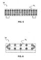
- FIG. 5 A specially designed execution of such a magazine is in Fig. 5 in a schematic frontal view and in Fig. 6 shown in a schematic side view.
- the twist loci TL are lined up in the example shown for provision on containers on elongate, for example rod-like elements, wherein the elongate elements can be moved in the manner of a circulating conveyor belt.
- the elements which receive the twist locks TL if an element has delivered all its twist locks TL mounted on it to the removal device / screwing device 16, continue to rotate in such a way that a another element can deliver his stored on him twist locks TL to the screw 16.
- the method of operation with the device according to the invention is preferably designed such that the workflow is set up so that when a magazine 14 is completely emptied of twist locks TL, only containers are placed on the device in the following, which are freed from twist locks TL should be filled up to the magazine 14 again with twist locks TL. This is followed by an operation in which containers are to be equipped with Twist-Locks TL again.
- the device may also be designed such that the magazines 14 are exchangeable and, for example, an access from the side of the device allows an empty magazine 14 to be replaced by a filled magazine 14 or vice versa.
- a replaceable magazine 14 preferably has, for example, pockets for accommodating a forklift fork.
- an arrangement of two Laschplättformen be provided side by side to z. B. can be operated with a tandem spreader, a two containers simultaneously gripping and transporting gantry crane, or a twin tandem with four containers.
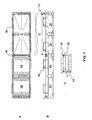
- a tandem spreader is in Fig. 7 in a schematic plan view ( Fig. 7A ), in a schematic side view ( Fig. 7B ) and in a schematic frontal view ( Fig. 7C ).
- a container C is shown in addition to the device according to the invention, which is equipped with twist lock container security fittings TL.
- Each stowage restrainer 16 consists of a rotary piston and a bushing, which via hydraulic or pneumatic means with a drive and a Ausschub in a laterally mounted, the twist holes TL in substantially vertical or horizontal alignment bearing magazine 14 spends.
- a helical, space-saving magazine guide is possible in addition to the above possibility.
- an independently operating lashing platform can be provided, which, according to a preferred embodiment, obtains the energy required for releasing and securing twist locks TL from or on a container C or for horizontal positioning of the platform from that energy which is deposited a container on the air bellows 10 of the platform is free.
- Such a device increases the flexibility in the use of lashing platforms and at the same time increases the productivity in the handling operation of containers.
Abstract
Description
Die Erfindung betrifft eine Vorrichtung nach den Merkmalen des Oberbegriffs des Hauptanspruches.The invention relates to a device according to the features of the preamble of the main claim.
Bei dem Be- und Entladen von Containerschiffen oder anderen containertransportierenden Einrichtungen werden sogenannte Twist-Locks dazu verwendet, in entsprechend vorgesehene Ausnehmungen an den Ecken des Containers eingesetzt, diese mit dem Stellplatz oder aneinander zu befestigen.When loading and unloading container ships or other container transporting facilities so-called twist locks are used to be used in correspondingly provided recesses at the corners of the container, to attach them to the pitch or to each other.
Ersichtlicherweise besteht das Bedürfnis, diese Twist-Locks, die nicht Teil des Containers sind, schnell anzubringen, bei Nichtgebrauch wieder vom Container zu lösen, und sicher bis zur nächsten Benutzung vorzuhalten, damit diese nicht verschmutzen oder verlustig gehen. So stellen nicht ordnungsgemäß gelagerte und im Fahrbereich von Großstaplern auf der Fahrbahn liegende Twist-Locks auch eine Gefahr für die Bereifung der Großstapler dar, die diese beschädigen können.Evidently, there is a need to quickly attach these twist locks, which are not part of the container, to release again from the container when not in use, and to keep it safe until the next use, so that they do not pollute or lose it. For example, incorrectly mounted twist locks that are located in the driving area of heavy goods vehicles on the roadway also pose a risk to the tires of the large forklift trucks, which can damage them.
Bisher wird Teil dieser Aufgabe, nämlich das Anbringen, durch komplizierte Vorrichtungen, wie sie beispielsweise in dem
Dabei besteht das weitere Problem, daß die Arbeiter erst dann an den Container herantreten dürfen, wenn dieser stillsteht. zuvor ist der Raum und umliegende Bereich, in den der Container abgesenkt wird, gesperrt. Weiter muß bisher der Kranführer aufwendig schätzen, in welche Höhe er den Container absenken soll, damit der händische Zugriff leicht erreichbar ist. dabei muß er seine Absenkgeschwindigkeit stufenweise stark verringern.There is the further problem that the workers may only approach the container when it is stationary. previously, the space and surrounding area into which the container is lowered, locked. Next, the crane operator has to estimate consuming, in what amount he should lower the container, so that the manual access is easily accessible. while he has to reduce his lowering speed gradually strong.
Die Erfindung dagegen löst die Aufgabe mit einer Vorrichtung mit den Merkmalen des Hauptanspruchs, indem sie nicht nur eine definierte Plattform schafft, auf der durch entsprechende Führungen ein Container an einem definierten Ort zu stehen kommt und neben dem eine vollständige Absperrung möglich ist (also ein Herantreten wie bisher vermieden wird).The invention, however, solves the problem with a device having the features of the main claim by not only creates a defined platform on which by appropriate guides a container comes to stand at a defined location and in addition to a complete barrier is possible (ie a approach as previously avoided).
Vielmehr, können wenn gewünscht, Krane oder Personen sich frei um die Plattform herum bewegen. Insbesondere ist der Zutritt nicht mehr unter schwebende Lasten an einen frei hängenden Container nötig, sondern - wenn überhaupt - zu einer Absetzplatte, auf der kein Container steht (die Arbeiter also auch frei sichtbar sind).Rather, if desired, cranes or people can move freely around the platform. In particular, access is no longer required under suspended loads to a free-hanging container, but - if any - to a settling plate on which no container is (the workers are therefore also freely visible).
Die Ver- und Entriegelung erfolgt automatisch. Vorgeschlagen wird eine druckluftbetriebene Schraubeinrichtung ähnlich den Radmutterwerkzeugen in KfZ-Werkstätten.The locking and unlocking takes place automatically. Proposed is a compressed air screwdriver similar to the Radmutterwerkzeugen in motor vehicle repair shops.
Allerdings ist zum Entfernen eines Twist-Lock nur eine ca. 90°-Drehung nötig. Diese erfolgt, indem die Twist-Locks in je einem in der Vorrichtung vorgesehenen (den antizipierten Orten der Containerecken gegenüberliegenden) Aufnahmeschlitz zu liegen kommen, der sie gegen eine in dem Twist-Lock vorgesehene Federspannung in die Verdreh-Stellung bringt, in der sie aus dem Container gelöst werden können.However, to remove a twist lock, only an approx. 90 ° turn is necessary. This is done by the twist locks in each provided in the device (the Anticipated locations of the container corners opposite) receiving slot come to rest, which brings them against a provided in the twist-lock spring tension in the twisting position in which they can be released from the container.
Nach Verdrehen eines Twist-Lock-Endes in eine definierte Stellung kann der Container abgehoben werden und die Twist-Locks verbleiben in der Aufnahme zurück.After twisting a twist-lock end into a defined position, the container can be lifted and the twist locks remain in the receptacle.
Durch an den vier Ecken vorgesehene Magazine kann bei einem Neueinsetzen von üblicherweise vier Twist-Locks an den Ecken des Containers das Einsetzen ebenso schnell und automatisiert erfolgen.By provided at the four corners magazines can be done just as quickly and automatically when re-inserting usually four twist locks at the corners of the container insertion.
Nun ist für den Einsatz in Häfen, auf denen schwere Flurförderzeuge frei umherfahren und Krane schienengeführt am Kai entlang fahren, der Einsatz einer solchen Plattform nicht ohne weiteres nachrüstbar. Weder können einfach Stromversorgungs-oder Druckluftleitungen ohne weiteres auf dem Hafenfeld verlegt werden, da diese durch die schweren Krane erheblichen Belastungen ausgesetzt wären oder sonst wie die freie Bewegung stören, noch kann einfach durch einen Motor Energie erzeugt werden, da dann ein "Nachtanken" in regelmäßigen Abständen nötig würde und unverhältnismäßige Wartungskosten hinzu kämen. Insbesondere die Versorgung mit Druckluft ist außerordentlich aufwendig.Now the use of such a platform can not be easily retrofitted for use in harbors where heavy forklift trucks drive around freely and cranes run along the quayside on rails. Neither power supply or compressed air lines can be easily moved to the port field, as they would be exposed by the heavy cranes considerable stress or otherwise interfere with the free movement, nor can be easily generated by a motor energy, then a "refueling" in regular intervals would be necessary and disproportionate maintenance costs would be added. In particular, the supply of compressed air is extremely expensive.
Daher ist die Erfindung dazu in der Lage, die zum Betätigen der Aufnahmen vorgesehene Druckluft dadurch zu erzeugen, dass unterhalb der Aufnahme, der Absetzplatte, Gasspeicher vorgesehen sind, die durch den darauf gestellten Container komprimiert werden und durch entsprechende elektronische oder pneumatische Ventilsteuerung das dann komprimierte Gas einem Druckgasspeicher zuführen.Therefore, the invention is able to produce the intended for actuating the recordings compressed air in that are provided below the recording, the settling plate, gas storage, which are compressed by the container placed on it and then compressed by appropriate electronic or pneumatic valve control Supply gas to a compressed gas storage tank.
Gegebenenfalls kann zur Versorgung der elektronischen Steuerung noch eine Batterie vorgesehen werden; diese kann sich durch einen Druckgasmotor aufladen oder nötigenfalls anderweitig aufgeladen werden.Optionally, a battery may be provided to supply the electronic control; this can be charged by a pressurized gas engine or charged otherwise if necessary.
Vorteilhaft ist insbesondere, dass der Container vor dem endgültigen Absetzen in Arbeitshöhe nicht mehr gestoppt werden muss, um beispielsweise per Hand Twist-Locks entfernen zu können. Auch kann der Kran vergleichsweise schnell die Container auf die auch als Laschplattform zu bezeichnende Vorrichtung zum Einsetzen von Twist-Lock-Container-Sicherungsbeschlägen aufsetzen, da durch das Gasdruckfederartige "gepolsterte" Verhalten der Laschplattform keine Beschädigungen des Containers zu befürchten sind.It is particularly advantageous that the container does not have to be stopped before final settling at working height, for example, to be able to remove twist locks manually. Also, the crane can relatively quickly the container on the lashing platform to be designated device for inserting Put on Twist-Lock-Container safety fittings, because the gas pressure spring-like "padded" behavior of the lashing platform does not cause any damage to the container.
Auch können mehrere bereits miteinander verbundene Container übereinander gesetzt auf die Vorrichtung gesetzt werden, wonach dann ein Kran beispielsweise drei Leercontainer auf einmal abtransportieren kann, die untereinander durch Twist-Locks verbunden sind. Dabei wird ein Kran die zuvor mit Twist-Locks versehenen oberen Container durch Führungen der Laschplattform unterstützt genau auf untere Container aufsetzen, wobei halbautomatische Twist-Locks selbst den sicheren Verbund herstellen.Also, several already interconnected containers can be placed one above the other on the device, after which a crane, for example, can carry away three empty containers at once, which are interconnected by twist locks. A crane will support the previously provided with Twist-Locks upper container supported by guides of the lashing platform exactly on lower containers, with semi-automatic Twist-Locks even make the secure bond.
Aufgrund der Lastverteilung des Unterrahmens wird zudem der unter dem Rahmen befindliche Boden im Portalbereich weniger beansprucht, es kann nicht zu einem harten Auftreffen des Containers auf beispielsweise eine Hafenbodenpflasterung kommen, bei der bisher unter Umständen das Problem bestand, dass empfindliche Ware innerhalb des Containers, aber auch der Asphalt im Portalbereich beschädigt werden konnte.Due to the load distribution of the subframe also located under the frame floor in the portal area is less stressed, it can not come to a hard impact of the container on, for example, a harbor floor paving, which previously may have had the problem that sensitive goods within the container, but also the asphalt in the portal area could be damaged.
Vorteilhafterweise ist die Plattform in einer einem 40" Container entsprechenden Ausführung vorhanden und kann damit wahlweise ein 20" Container, 2 x 20" Container, ein 40" oder sogar bei entsprechenden Überhängen ein 45" Container aufgenommen werden. Hierzu kann alternativ die Absetzplatte pneumatisch oder hydraulisch teleskopierbar auf 45" ausgelegt werden.Advantageously, the platform is in a 40 "container corresponding design and can thus either a 20" container, 2 x 20 "container, a 40" or even with appropriate overhangs a 45 "container be added hydraulically telescopic to 45 ".
Weitere Merkmale und Vorteile der Erfindung ergeben sich aus nachfolgender Beschreibung eines bevorzugten Ausführungsbeispiels anhand der beigefügten Zeichnung. Dabei zeigt:
- Fig. 1
- die erfindungsgemäße Vorrichtung in seitlicher Darstellung,
- Fig. 2
- die Vorrichtung aus
Fig. 1 in einem nichtbelasteten Zustand mit schema- tisch angedeuteten Magazinen für Twist-Lock-Beschläge, z.B. an jeder Ecke, - Fig. 3
- eine Draufsicht auf die Vorrichtung aus
Fig. 1 mit acht Schraubeinrich- tungen, - Fig. 4
- eine Draufsicht auf die Vorrichtung aus
Fig. 1 mit acht, mit Magazinen versehenen Schraubeinrichtungen und (gestrichelt angedeuteten) Luft- bälgen, - Fig. 5
- eine schematische Frontalansicht eines speziell ausgebildeten Magazins für die erfindungsgemäße Vorrichtung,
- Fig. 6
- eine schematische Seitenansicht des Magazins aus
Fig. 5 und - Fig. 7
- ein besonders bevorzugtes Ausführungsbeispiel der Erfindung in einer schematischen Draufsicht (A), in einer schematischen Seitenansicht (B) und in einer schematischen Frontalansicht (C).
- Fig. 1
- the device according to the invention in a lateral view,
- Fig. 2
- the device off
Fig. 1 in a non-loaded state with schematically indicated magazines for twist-lock fittings, eg at each corner, - Fig. 3
- a plan view of the device
Fig. 1 with eight screwing devices, - Fig. 4
- a plan view of the device
Fig. 1 with eight screw-type devices provided with magazines and (bellowed) air bellows, - Fig. 5
- a schematic frontal view of a specially designed magazine for the device according to the invention,
- Fig. 6
- a schematic side view of the magazine
Fig. 5 and - Fig. 7
- a particularly preferred embodiment of the invention in a schematic plan view (A), in a schematic side view (B) and in a schematic frontal view (C).
In
In der
Durch entsprechend in den Ecken und/oder Seiten der Plattform vorgesehene, jedenfalls den Lagerorten im Container benachbarte, druelduftbetriebene Twist-Locks TL greifende und rückdrehende Entnahmevorrichtungen 16 (vgl.
Bei bisher üblichen Zyklen von 30 Containern pro Stunde kann eine Person per Hand die Twist-Locks TL in ein bereitstehendes, daneben liegendes Magazin legen und gegebenenfalls die Twist-Locks TL auf ihren Zustand optisch überprüfen. Im Gegensatz zur manuellen Entnahme der Twist-Locks TL aus einem Container ergibt sich der große Vorteil, dass der Container selber nicht mehr während seines Transportes längere Zeit angehalten werden muss und insbesondere nicht mehr von einem Kranführer in eine beispielsweise 1,50 m über dem Boden schwebende Position per Augenmaß langsam verbracht werden muss, sondern eine vorbestimmte, ggf. durch mechanische Führungen 18 erleichterte Position schnell angefahren werden kann und nach kurzer, durch gleichzeitige Auslösung aller vier Twist-Locks TL sich ergebenden Wartezeit, der Container gleich weiter befördert werden kann.In usual cycles of 30 containers per hour, a person can manually put the twist locks TL in a ready-to-lie, lying magazine and if necessary, optically check the twist locks TL for their condition. In contrast to the manual removal of the twist locks TL from a container, there is the great advantage that the container itself no longer has to be stopped during its transport for a long time and in particular no longer by a crane operator in, for example, 1.50 m above the ground hovering position must be spent slowly by eye, but a predetermined, possibly facilitated by
Selbstverständlich lässt sich in einem Ladevorgang die Vorrichtung auch anders benutzen, nämlich dass entsprechende Twist-Locks TL in den Staustückhaltern 16 schon bereit stehen und durch Aufsetzen des Containers selbständig in den Befestigungslöchern verriegeln (wobei dies die namesgemäße Funktionalität der Twist-Locks TL ist, nämlich, dass sie, obwohl rechtwinklig zum Befestigungsloch angeordnet, sich beim Einschubvorgang verdrehen und dann selbständig federvorgespannt in eine Verriegelungsposition verriegeln). Alternativ können Raumtwistlocks TL gesteuert in einen Container verriegeln.Of course, in a loading operation, the device can also be used differently, namely that corresponding twist locks TL are already prepared in the
Auch bei diesem Vorgang wird wieder kinetische Energie dazu genutzt, pneumatisch mittels Verdichtern als Arbeitsenergie in Vorratsspeicher eingebracht zu werden. Selbstverständlich ist auch ein Arbeiten mit Fremdenergie möglich, und eine Rechnersteuerung kann vorgesehen werden, um die Bevorratung und das Entfernen der Twist-Locks TL zu managen, d. h., aus einem Magazin 14 gegebenenfalls mehr Twist-Locks TL anzufordern oder überschüssige Anzahlen an Twist-Locks TL an ein solches Magazin 14 abzutransportieren.Also in this process kinetic energy is used again to be introduced pneumatically by means of compressors as working energy in storage. Of course, working with external power is also possible, and a computer control can be provided to manage the stocking and removal of the twist locks TL, i. h. Request from a
Eine besonders gestaltete Ausführung eines derartigen Magazins ist in
Die Arbeitsweise mit der erfindungsgemäßen Vorrichtung ist bevorzugt derart ausgestaltet, dass der Arbeitsablauf so eingerichtet ist, dass wenn ein Magazin 14 vollständig von Twist-Locks TL entleert ist, im Folgenden nur Container auf die Vorrichtung aufgesetzt werden, die von Twist-Locks TL befreit werden sollen bis das Magazin 14 wieder mit Twist-Locks TL aufgefüllt ist. Danach schließt sich ein Arbeitsgang an, bei dem wieder Container mit Twist-Locks TL bestückt werden sollen.The method of operation with the device according to the invention is preferably designed such that the workflow is set up so that when a
Alternativ dazu kann die Vorrichtung aber auch derart ausgebildet sein, dass die Magazine 14 austauschbar eingerichtet sind und beispielsweise durch einen Zugriff von der Seite der Vorrichtung ein leeres Magazin 14 durch ein gefülltes Magazin 14 oder umgekehrt ausgetauscht werden kann. Bevorzugt weist solch ein auswechselbares Magazin 14 beispielsweise Taschen zur Aufnahme einer Gabelstaplergabel auf.Alternatively, however, the device may also be designed such that the
Selbstverständlich kann auch eine Anordnung zweier Laschplättformen nebeneinander vorgesehen werden, um z. B. mit einem Tandem-Spreader, einem zwei Container gleichzeitig greifenden und transportierenden Portalkran bedient werden zu können, oder einem Twin-Tandem mit vier Containern. Eine derartige Ausführung der erfindungsgemäßen Vorrichtung für einen Tandem-Spreader ist in
Jeder Staustückrückhalter 16 besteht aus einem Drehkolben und einer Buchse, die über Hydraulik oder Pneumatik mit einem Antrieb und einem Ausschub in ein seitlich angebrachtes, die Twist-Lochs TL in im wesentlichen vertikaler oder horizontaler Ausrichtung aneinander lagerndes Magazin 14 verbringt. Weiter ist auch neben der oben genannten Möglichkeit eine schneckenförmige, raumsparende Magazinführung möglich.Each stowage restrainer 16 consists of a rotary piston and a bushing, which via hydraulic or pneumatic means with a drive and a Ausschub in a laterally mounted, the twist holes TL in substantially vertical or horizontal
Schließlich sei noch darauf hingewiesen, dass im Umschlagsbetrieb beispielsweise durch Gezeiten, starke Winde oder durch Schiffsverkehr verursachte Wellenbewegungen Schiffsbewegungen bedingen, die mitunter eine geringfügige Anpassung der relativen horizontalen Position der Containerbrücke zur Laschplattform notwendig machen. Diese Horizontalbewegung der gesamten Laschplattform oder wenigstens des den Container C aufnehmenden Auflagerahmens der Laschplattform kann ebenfalls durch die in den Verdichtern gespeicherte Arbeitsenergie ermöglicht werden und automatisch oder manuell gesteuert sein.Finally, it should be noted that in Umschlagbetrieb example caused by tides, high winds or ship traffic caused wave movements Ship movements, which sometimes necessitate a slight adjustment of the relative horizontal position of the container bridge to the lashing platform. This horizontal movement of the entire lashing platform or at least of the container C receiving support frame of the lashing platform can also be made possible by the stored energy in the compressors and be controlled automatically or manually.
Erfindungsgemäß kann somit eine selbständig arbeitende Laschplattform bereit gestellt werden, die nach einer bevorzugten Ausführung die die zum Lösen und Befestigen von Twist-Locks TL von bzw. an einem Container C oder zum horizontalen Positionieren der Plattform notwendige Energie aus derjenigen Energie bezieht, die beim Absetzen eines Containers auf die Luftbälge 10 der Plattform frei wird. Eine derartige Vorrichtung erhöht die Flexibilität im Einsatz von Laschplattformen und steigert zugleich die Produktivität im Umschlagsbetrieb von Containern.According to the invention, therefore, an independently operating lashing platform can be provided, which, according to a preferred embodiment, obtains the energy required for releasing and securing twist locks TL from or on a container C or for horizontal positioning of the platform from that energy which is deposited a container on the air bellows 10 of the platform is free. Such a device increases the flexibility in the use of lashing platforms and at the same time increases the productivity in the handling operation of containers.
Claims (6)
- Device for inserting and removing securing fittings (TL) for twist-lock containers, having a support plate for a container (C), which is provided with a screwing mechanism (16) with a slot gripper for each expected position of a securing fitting (TL) for the twist-lock container,
characterized in that
below the support plate, gas-storage units are provided to which can be applied, by the support plate and a container (C) placed there upon, its gravity, an electronic valve control for passing on gases that have been compressed in the gas-storage units being connected via pipes to a pressurized-gas reservoir, and further pipes connecting the latter with the screwing mechanisms (16),
the screwing mechanisms (16) being driven pneumatically. - Device according to Claim 1, characterized by magazines (14) for securing fittings (TL) provided for each screwing mechanism (16) for twist-lock containers.
- Device according to Claim 2, characterized in that the magazines (14) are designed as running tracks formed by inclined rods inside which the securing fittings (TL) for twist-lock containers are supported vertically so that they rest vertically and can slide along the rods.
- Device according to one of the preceding claims, characterized by vertical corner guides that tower the height of a container (C) and that on sliding along the vertical corner edges when lowering a container (C) into the device, confront the storage positions of the twist locks (TL) in the container (C) with the slot grippers.
- Method for removing securing fittings (TL) for twist-lock containers from a container (C), characterized by the following steps:- setting down a container (C) on a support plate for containers (C), that can be lowered and is located, pre-tensioned by a spring, in an upper position and exhibits for each securing fitting (TL) for twist-lock containers a pneumatically driven screwing mechanism (16) having a slot gripper, and is provided with gas-storage units that are arranged below the support plate and to which can be applied by the support plate with a container (C) placed there upon its gravity, an electronic or pneumatic valve control for passing on gases that have been compressed in the gas-storage units being connected via pipes to a pressurized-gas reservoir, and further pipes connecting the pressurized-gas reservoir with the screwing mechanisms (16), so that on lowering the support plate, compressed air is delivered to the compressed-air screwing devices (16),
it being the case that at the end of the lowering process the screwing mechanisms (16) have rotated the securing fittings (TL) for twist-lock containers into a position no longer attached to the container (C),- lifting the container (C), and- removing the securing fittings (TL) for twist-lock containers from the screwing mechanisms (16). - Method for equipping a container (C) with securing fittings (TL) for twist-lock containers, characterized by the following steps:- placing the securing fittings (TL) for twist-lock containers on screwing mechanisms (16) of a support plate for containers (C), that can be lowered and is located, pre-tensioned by a spring, in an upper position and exhibits at each expected position for a securing fitting (TL) for twist-lock containers a pneumatically driven screwing mechanism (16) having a slot gripper, and is provided with gas-storage units that are provided below the support plate and to which can be applied, by the support plate with a container (C) placed there upon, its gravity, an electronic or pneumatic valve control for passing on gases that have been compressed in the gas-storage units being connected via pipes to a pressurized-gas reservoir, and further pipes connecting the pressurized-gas reservoir with the screwing mechanisms (16),- setting down a container (C) on the support plate, so that compressed air is delivered to the compressed-air screwing devices (16) on lowering the support plate,
it being the case that at the end of the lowering process the screwing mechanisms (16) have rotated the securing fittings (TL) for twist-lock containers into a position attached to the container (C),- lifting the container (C) with the securing fittings (TL) for twist-lock containers out of the screwing mechanisms (16).
Priority Applications (1)
| Application Number | Priority Date | Filing Date | Title |
|---|---|---|---|
| PL07764319T PL1999040T3 (en) | 2006-03-02 | 2007-03-01 | Device and method for inserting and removing securing fittings for twist-lock containers |
Applications Claiming Priority (3)
| Application Number | Priority Date | Filing Date | Title |
|---|---|---|---|
| DE200620003435 DE202006003435U1 (en) | 2006-03-02 | 2006-03-02 | Assembly to insert container twist-lock by twist-lock fittings remotely operated by hydraulic or pneumatic power |
| DE102006015807A DE102006015807A1 (en) | 2006-03-02 | 2006-04-03 | Device and method for inserting and removing twist-lock container securing fittings |
| PCT/DE2007/000380 WO2007098749A1 (en) | 2006-03-02 | 2007-03-01 | Device and method for inserting and removing securing fittings for twist-lock containers |
Publications (2)
| Publication Number | Publication Date |
|---|---|
| EP1999040A1 EP1999040A1 (en) | 2008-12-10 |
| EP1999040B1 true EP1999040B1 (en) | 2010-09-01 |
Family
ID=38134963
Family Applications (1)
| Application Number | Title | Priority Date | Filing Date |
|---|---|---|---|
| EP07764319A Not-in-force EP1999040B1 (en) | 2006-03-02 | 2007-03-01 | Device and method for inserting and removing securing fittings for twist-lock containers |
Country Status (11)
| Country | Link |
|---|---|
| US (1) | US7779604B2 (en) |
| EP (1) | EP1999040B1 (en) |
| AT (1) | ATE479611T1 (en) |
| AU (1) | AU2007219527B2 (en) |
| DE (2) | DE102006015807A1 (en) |
| DK (1) | DK1999040T3 (en) |
| ES (1) | ES2348754T3 (en) |
| NZ (1) | NZ570328A (en) |
| PL (1) | PL1999040T3 (en) |
| PT (1) | PT1999040E (en) |
| WO (1) | WO2007098749A1 (en) |
Families Citing this family (18)
| Publication number | Priority date | Publication date | Assignee | Title |
|---|---|---|---|---|
| US8690511B2 (en) * | 2007-03-09 | 2014-04-08 | John J. Lanigan, Sr. | Inline terminal, hub and distribution system |
| US20080243301A1 (en) * | 2007-03-26 | 2008-10-02 | Lanigan John J | Inline terminal system |
| US8465244B2 (en) * | 2007-05-30 | 2013-06-18 | Mi-Jack Products, Inc. | Distribution system |
| US8585347B2 (en) | 2007-06-26 | 2013-11-19 | Mi-Jack Products, Inc. | Hub and distribution system |
| US8790062B2 (en) * | 2008-04-01 | 2014-07-29 | Mi-Jack Products, Inc. | Distribution system |
| DE102008061204B3 (en) | 2008-12-09 | 2010-03-11 | Rainer Kapelski | Magazine for storing twist locks |
| DE102009007295A1 (en) * | 2009-02-03 | 2010-08-12 | Hit-Machine Technology Gmbh | Apparatus for removing or adding coupling elements designated as twistlocks from or to container corner fittings |
| DE102009020999A1 (en) * | 2009-05-12 | 2010-11-18 | Hydac System Gmbh | lashing platform |
| DE102009031272B3 (en) | 2009-06-30 | 2010-12-30 | Kalp Gmbh | Lashing platform with magazine for twistlocks |
| DE102009060637B4 (en) | 2009-12-28 | 2018-07-26 | Kalp Gmbh | System for automatically inserting twistlocks into and / or removing twistlocks from container fittings arranged on a container |
| SE534492C2 (en) * | 2010-02-03 | 2011-09-06 | Ship To Shore Technology Holding B V | Container handling device, use of such and method of unloading and loading |
| DE102010007675B3 (en) * | 2010-02-10 | 2011-06-30 | Kapelski, Rainer, 24401 | slot gripper |
| DE102010007674B3 (en) * | 2010-02-10 | 2011-06-30 | Kapelski, Rainer, 24401 | lashing platform |
| DE102010021822B3 (en) | 2010-05-28 | 2011-07-21 | Kapelski, Rainer, 24401 | Completely autonomous lashing platform |
| US9981812B2 (en) | 2014-06-05 | 2018-05-29 | Steve Foldesi | Automated handling of shipping containers and connectors |
| CN108000089B (en) * | 2017-11-09 | 2019-08-23 | 上海江南长兴造船有限责任公司 | A kind of insulated case assembly auxiliary device |
| CN113002401B (en) * | 2021-03-31 | 2022-09-27 | 青岛大学附属医院 | Medical alcohol conveyer |
| CN115258057A (en) * | 2022-06-15 | 2022-11-01 | 中船澄西船舶修造有限公司 | Button lock box layout structure of refrigeration centralized box ship |
Family Cites Families (11)
| Publication number | Priority date | Publication date | Assignee | Title |
|---|---|---|---|---|
| US3827384A (en) * | 1972-04-21 | 1974-08-06 | T Lunde | Containership |
| BR7804690A (en) * | 1977-07-21 | 1979-02-06 | Schaefer Homberg Gmbh | MACHINE FOR THE APPLICATION OF RIVETS, BUTTONS AND SIMILARS |
| US5356249A (en) * | 1993-03-30 | 1994-10-18 | Buffers Ab | Automatic securing system for locking and unlocking a freight container to a load carrier |
| NL1012849C2 (en) * | 1999-08-18 | 2001-02-20 | Univ Delft Tech | Method and device for applying or removing a semi-automatic twist lock. |
| US6554557B1 (en) * | 2002-02-04 | 2003-04-29 | Paceco Corp. | Inter-box connector (IBC) installation and removal system |
| US20060115350A1 (en) * | 2003-01-15 | 2006-06-01 | Otto Weis | Device for automatically installing and reoving twistlocks |
| DE10301197A1 (en) | 2003-01-15 | 2004-08-19 | Noell Crane Systems Gmbh | Device for the automatic removal and installation of twistlocks |
| KR101222365B1 (en) * | 2004-08-30 | 2013-01-15 | 엔에스엘 엔지니어링 피티이 리미티드 | Twist-lock handling system |
| AU2005335498A1 (en) * | 2005-08-16 | 2007-02-22 | Sunrose Tecdesign Pte Ltd. | Inter-box connector (IBC) storage and handling system |
| ITMI20052338A1 (en) * | 2005-12-06 | 2007-06-07 | Fata Fab App Sollevamento | CONTAINER TRANSFER PLANT BETWEEN SHIP AND WAREHOUSE |
| US7556472B2 (en) * | 2006-04-24 | 2009-07-07 | Fuelcell Energy, Inc. | Assembly for and method of housing an object, such as fuel cell balance of plant equipment, for transport to and storage at a user location |
-
2006
- 2006-04-03 DE DE102006015807A patent/DE102006015807A1/en not_active Withdrawn
-
2007
- 2007-03-01 PT PT07764319T patent/PT1999040E/en unknown
- 2007-03-01 EP EP07764319A patent/EP1999040B1/en not_active Not-in-force
- 2007-03-01 DE DE502007004923T patent/DE502007004923D1/en active Active
- 2007-03-01 ES ES07764319T patent/ES2348754T3/en active Active
- 2007-03-01 AU AU2007219527A patent/AU2007219527B2/en not_active Ceased
- 2007-03-01 US US12/224,365 patent/US7779604B2/en not_active Expired - Fee Related
- 2007-03-01 WO PCT/DE2007/000380 patent/WO2007098749A1/en active Application Filing
- 2007-03-01 AT AT07764319T patent/ATE479611T1/en active
- 2007-03-01 NZ NZ570328A patent/NZ570328A/en not_active IP Right Cessation
- 2007-03-01 DK DK07764319.5T patent/DK1999040T3/en active
- 2007-03-01 PL PL07764319T patent/PL1999040T3/en unknown
Also Published As
| Publication number | Publication date |
|---|---|
| AU2007219527B2 (en) | 2012-06-28 |
| US7779604B2 (en) | 2010-08-24 |
| DK1999040T3 (en) | 2010-12-13 |
| ES2348754T3 (en) | 2010-12-13 |
| PL1999040T3 (en) | 2010-12-31 |
| DE102006015807A1 (en) | 2007-09-06 |
| ATE479611T1 (en) | 2010-09-15 |
| NZ570328A (en) | 2010-06-25 |
| AU2007219527A1 (en) | 2007-09-07 |
| US20090199517A1 (en) | 2009-08-13 |
| DE502007004923D1 (en) | 2010-10-14 |
| PT1999040E (en) | 2010-09-30 |
| EP1999040A1 (en) | 2008-12-10 |
| WO2007098749A1 (en) | 2007-09-07 |
Similar Documents
| Publication | Publication Date | Title |
|---|---|---|
| EP1999040B1 (en) | Device and method for inserting and removing securing fittings for twist-lock containers | |
| EP3107860B1 (en) | Method and apparatus for storing and retrieving or shifting containers in high-bay warehouses | |
| DE112014003015B4 (en) | Mobile crane | |
| DE102009025052A1 (en) | System for changing a battery of a ground-based transport vehicle, in particular a driverless heavy-duty transport vehicle for ISO containers | |
| DE102009049563B4 (en) | Shuttle channel warehouse, shuttle station, shuttle and procedures for operating the shuttle channel warehouse | |
| EP1585690B1 (en) | Device for automatically mounting or removing twistlocks | |
| EP1313663B1 (en) | Device for transporting people by a spreader | |
| DE102012019248A1 (en) | Tower Crane | |
| EP2448844B1 (en) | Lashing platform having a magazine for twistlocks | |
| DE102018205933A1 (en) | Telescope holder for moving containers in high-bay warehouses | |
| DE19958501A1 (en) | Lifting device to increase the performance of a handling device for ISO containers | |
| DE202006003435U1 (en) | Assembly to insert container twist-lock by twist-lock fittings remotely operated by hydraulic or pneumatic power | |
| EP2429926B1 (en) | Lashing platform | |
| EP3630572A1 (en) | Device for transporting long welded rails | |
| EP0636080A1 (en) | Lifting frame | |
| EP0641685B1 (en) | Device for securing the transport of containers | |
| DE102014108016A1 (en) | Method for loading and unloading a route | |
| DE102015115323A1 (en) | Storage and retrieval unit | |
| DE1156321B (en) | Vehicle with lifting device for the transport of prefabricated garages or the like. | |
| AT410960B (en) | STORAGE SYSTEM | |
| WO2014048966A2 (en) | Stackable bundle of compressed gas cylinders | |
| DE102013010455B4 (en) | Method for producing a security platform | |
| EP0997371A2 (en) | Vehicle for the transport of heavy loads | |
| DE10234310A1 (en) | Loading plant esp. for handling of palettes and containers, for cargo ships has associated satellite vehicle, e.g. transport and handling gate, driven onto loading platform, with rollers for containers | |
| DE202016006258U1 (en) | Apparatus for loading and unloading of containers and towed road vehicle with such a device |
Legal Events
| Date | Code | Title | Description |
|---|---|---|---|
| PUAI | Public reference made under article 153(3) epc to a published international application that has entered the european phase |
Free format text: ORIGINAL CODE: 0009012 |
|
| 17P | Request for examination filed |
Effective date: 20080829 |
|
| AK | Designated contracting states |
Kind code of ref document: A1 Designated state(s): AT BE BG CH CY CZ DE DK EE ES FI FR GB GR HU IE IS IT LI LT LU LV MC NL PL PT RO SE SI SK TR |
|
| 17Q | First examination report despatched |
Effective date: 20090610 |
|
| GRAP | Despatch of communication of intention to grant a patent |
Free format text: ORIGINAL CODE: EPIDOSNIGR1 |
|
| GRAS | Grant fee paid |
Free format text: ORIGINAL CODE: EPIDOSNIGR3 |
|
| GRAA | (expected) grant |
Free format text: ORIGINAL CODE: 0009210 |
|
| AK | Designated contracting states |
Kind code of ref document: B1 Designated state(s): AT BE BG CH CY CZ DE DK EE ES FI FR GB GR HU IE IS IT LI LT LU LV MC NL PL PT RO SE SI SK TR |
|
| REG | Reference to a national code |
Ref country code: GB Ref legal event code: FG4D Free format text: NOT ENGLISH |
|
| REG | Reference to a national code |
Ref country code: CH Ref legal event code: EP |
|
| REG | Reference to a national code |
Ref country code: IE Ref legal event code: FG4D Free format text: LANGUAGE OF EP DOCUMENT: GERMAN Ref country code: NL Ref legal event code: T3 |
|
| REG | Reference to a national code |
Ref country code: PT Ref legal event code: SC4A Free format text: AVAILABILITY OF NATIONAL TRANSLATION Effective date: 20100917 |
|
| REF | Corresponds to: |
Ref document number: 502007004923 Country of ref document: DE Date of ref document: 20101014 Kind code of ref document: P |
|
| REG | Reference to a national code |
Ref country code: ES Ref legal event code: FG2A Effective date: 20101129 |
|
| REG | Reference to a national code |
Ref country code: SE Ref legal event code: TRGR |
|
| REG | Reference to a national code |
Ref country code: DK Ref legal event code: T3 |
|
| PG25 | Lapsed in a contracting state [announced via postgrant information from national office to epo] |
Ref country code: LT Free format text: LAPSE BECAUSE OF FAILURE TO SUBMIT A TRANSLATION OF THE DESCRIPTION OR TO PAY THE FEE WITHIN THE PRESCRIBED TIME-LIMIT Effective date: 20100901 |
|
| LTIE | Lt: invalidation of european patent or patent extension |
Effective date: 20100901 |
|
| PG25 | Lapsed in a contracting state [announced via postgrant information from national office to epo] |
Ref country code: CY Free format text: LAPSE BECAUSE OF FAILURE TO SUBMIT A TRANSLATION OF THE DESCRIPTION OR TO PAY THE FEE WITHIN THE PRESCRIBED TIME-LIMIT Effective date: 20100901 Ref country code: SI Free format text: LAPSE BECAUSE OF FAILURE TO SUBMIT A TRANSLATION OF THE DESCRIPTION OR TO PAY THE FEE WITHIN THE PRESCRIBED TIME-LIMIT Effective date: 20100901 |
|
| REG | Reference to a national code |
Ref country code: IE Ref legal event code: FD4D |
|
| PG25 | Lapsed in a contracting state [announced via postgrant information from national office to epo] |
Ref country code: LV Free format text: LAPSE BECAUSE OF FAILURE TO SUBMIT A TRANSLATION OF THE DESCRIPTION OR TO PAY THE FEE WITHIN THE PRESCRIBED TIME-LIMIT Effective date: 20100901 Ref country code: GR Free format text: LAPSE BECAUSE OF FAILURE TO SUBMIT A TRANSLATION OF THE DESCRIPTION OR TO PAY THE FEE WITHIN THE PRESCRIBED TIME-LIMIT Effective date: 20101202 |
|
| PG25 | Lapsed in a contracting state [announced via postgrant information from national office to epo] |
Ref country code: EE Free format text: LAPSE BECAUSE OF FAILURE TO SUBMIT A TRANSLATION OF THE DESCRIPTION OR TO PAY THE FEE WITHIN THE PRESCRIBED TIME-LIMIT Effective date: 20100901 Ref country code: CZ Free format text: LAPSE BECAUSE OF FAILURE TO SUBMIT A TRANSLATION OF THE DESCRIPTION OR TO PAY THE FEE WITHIN THE PRESCRIBED TIME-LIMIT Effective date: 20100901 Ref country code: RO Free format text: LAPSE BECAUSE OF FAILURE TO SUBMIT A TRANSLATION OF THE DESCRIPTION OR TO PAY THE FEE WITHIN THE PRESCRIBED TIME-LIMIT Effective date: 20100901 Ref country code: SK Free format text: LAPSE BECAUSE OF FAILURE TO SUBMIT A TRANSLATION OF THE DESCRIPTION OR TO PAY THE FEE WITHIN THE PRESCRIBED TIME-LIMIT Effective date: 20100901 Ref country code: IS Free format text: LAPSE BECAUSE OF FAILURE TO SUBMIT A TRANSLATION OF THE DESCRIPTION OR TO PAY THE FEE WITHIN THE PRESCRIBED TIME-LIMIT Effective date: 20110101 |
|
| PLBE | No opposition filed within time limit |
Free format text: ORIGINAL CODE: 0009261 |
|
| STAA | Information on the status of an ep patent application or granted ep patent |
Free format text: STATUS: NO OPPOSITION FILED WITHIN TIME LIMIT |
|
| 26N | No opposition filed |
Effective date: 20110606 |
|
| REG | Reference to a national code |
Ref country code: DE Ref legal event code: R097 Ref document number: 502007004923 Country of ref document: DE Effective date: 20110606 |
|
| PG25 | Lapsed in a contracting state [announced via postgrant information from national office to epo] |
Ref country code: MC Free format text: LAPSE BECAUSE OF NON-PAYMENT OF DUE FEES Effective date: 20110331 |
|
| REG | Reference to a national code |
Ref country code: CH Ref legal event code: PL |
|
| PG25 | Lapsed in a contracting state [announced via postgrant information from national office to epo] |
Ref country code: LI Free format text: LAPSE BECAUSE OF NON-PAYMENT OF DUE FEES Effective date: 20110331 Ref country code: CH Free format text: LAPSE BECAUSE OF NON-PAYMENT OF DUE FEES Effective date: 20110331 |
|
| REG | Reference to a national code |
Ref country code: AT Ref legal event code: MM01 Ref document number: 479611 Country of ref document: AT Kind code of ref document: T Effective date: 20120301 |
|
| PG25 | Lapsed in a contracting state [announced via postgrant information from national office to epo] |
Ref country code: LU Free format text: LAPSE BECAUSE OF NON-PAYMENT OF DUE FEES Effective date: 20110301 |
|
| PG25 | Lapsed in a contracting state [announced via postgrant information from national office to epo] |
Ref country code: AT Free format text: LAPSE BECAUSE OF NON-PAYMENT OF DUE FEES Effective date: 20120301 |
|
| PG25 | Lapsed in a contracting state [announced via postgrant information from national office to epo] |
Ref country code: BG Free format text: LAPSE BECAUSE OF FAILURE TO SUBMIT A TRANSLATION OF THE DESCRIPTION OR TO PAY THE FEE WITHIN THE PRESCRIBED TIME-LIMIT Effective date: 20101201 |
|
| PG25 | Lapsed in a contracting state [announced via postgrant information from national office to epo] |
Ref country code: HU Free format text: LAPSE BECAUSE OF FAILURE TO SUBMIT A TRANSLATION OF THE DESCRIPTION OR TO PAY THE FEE WITHIN THE PRESCRIBED TIME-LIMIT Effective date: 20100901 |
|
| REG | Reference to a national code |
Ref country code: DE Ref legal event code: R081 Ref document number: 502007004923 Country of ref document: DE Owner name: KALP GMBH, DE Free format text: FORMER OWNER: KAPELSKI, RAINER, 24401 BOEEL, DE Effective date: 20150305 |
|
| REG | Reference to a national code |
Ref country code: FR Ref legal event code: PLFP Year of fee payment: 10 |
|
| REG | Reference to a national code |
Ref country code: FR Ref legal event code: PLFP Year of fee payment: 11 |
|
| REG | Reference to a national code |
Ref country code: FR Ref legal event code: PLFP Year of fee payment: 12 |
|
| REG | Reference to a national code |
Ref country code: DE Ref legal event code: R082 Ref document number: 502007004923 Country of ref document: DE Representative=s name: LOBEMEIER, MARTIN LANDOLF, DR., DE |
|
| PGFP | Annual fee paid to national office [announced via postgrant information from national office to epo] |
Ref country code: IE Payment date: 20190322 Year of fee payment: 13 Ref country code: FR Payment date: 20190322 Year of fee payment: 13 Ref country code: GB Payment date: 20190320 Year of fee payment: 13 Ref country code: IT Payment date: 20190325 Year of fee payment: 13 Ref country code: PL Payment date: 20190218 Year of fee payment: 13 Ref country code: DE Payment date: 20181227 Year of fee payment: 13 Ref country code: FI Payment date: 20190321 Year of fee payment: 13 |
|
| PGFP | Annual fee paid to national office [announced via postgrant information from national office to epo] |
Ref country code: SE Payment date: 20190320 Year of fee payment: 13 Ref country code: DK Payment date: 20190322 Year of fee payment: 13 Ref country code: NL Payment date: 20190320 Year of fee payment: 13 Ref country code: BE Payment date: 20190320 Year of fee payment: 13 Ref country code: TR Payment date: 20190222 Year of fee payment: 13 |
|
| PGFP | Annual fee paid to national office [announced via postgrant information from national office to epo] |
Ref country code: ES Payment date: 20190418 Year of fee payment: 13 Ref country code: PT Payment date: 20190225 Year of fee payment: 13 |
|
| REG | Reference to a national code |
Ref country code: DE Ref legal event code: R119 Ref document number: 502007004923 Country of ref document: DE |
|
| REG | Reference to a national code |
Ref country code: FI Ref legal event code: MAE |
|
| PG25 | Lapsed in a contracting state [announced via postgrant information from national office to epo] |
Ref country code: FI Free format text: LAPSE BECAUSE OF NON-PAYMENT OF DUE FEES Effective date: 20200301 |
|
| REG | Reference to a national code |
Ref country code: DK Ref legal event code: EBP Effective date: 20200331 |
|
| REG | Reference to a national code |
Ref country code: NL Ref legal event code: MM Effective date: 20200401 |
|
| REG | Reference to a national code |
Ref country code: BE Ref legal event code: MM Effective date: 20200331 |
|
| PG25 | Lapsed in a contracting state [announced via postgrant information from national office to epo] |
Ref country code: NL Free format text: LAPSE BECAUSE OF NON-PAYMENT OF DUE FEES Effective date: 20200401 |
|
| PG25 | Lapsed in a contracting state [announced via postgrant information from national office to epo] |
Ref country code: PT Free format text: LAPSE BECAUSE OF NON-PAYMENT OF DUE FEES Effective date: 20201002 Ref country code: FR Free format text: LAPSE BECAUSE OF NON-PAYMENT OF DUE FEES Effective date: 20200331 Ref country code: IE Free format text: LAPSE BECAUSE OF NON-PAYMENT OF DUE FEES Effective date: 20200301 Ref country code: SE Free format text: LAPSE BECAUSE OF NON-PAYMENT OF DUE FEES Effective date: 20200302 Ref country code: DE Free format text: LAPSE BECAUSE OF NON-PAYMENT OF DUE FEES Effective date: 20201001 |
|
| PG25 | Lapsed in a contracting state [announced via postgrant information from national office to epo] |
Ref country code: BE Free format text: LAPSE BECAUSE OF NON-PAYMENT OF DUE FEES Effective date: 20200331 |
|
| GBPC | Gb: european patent ceased through non-payment of renewal fee |
Effective date: 20200301 |
|
| PG25 | Lapsed in a contracting state [announced via postgrant information from national office to epo] |
Ref country code: GB Free format text: LAPSE BECAUSE OF NON-PAYMENT OF DUE FEES Effective date: 20200301 Ref country code: DK Free format text: LAPSE BECAUSE OF NON-PAYMENT OF DUE FEES Effective date: 20200331 |
|
| REG | Reference to a national code |
Ref country code: ES Ref legal event code: FD2A Effective date: 20210726 |
|
| PG25 | Lapsed in a contracting state [announced via postgrant information from national office to epo] |
Ref country code: IT Free format text: LAPSE BECAUSE OF NON-PAYMENT OF DUE FEES Effective date: 20200301 |
|
| PG25 | Lapsed in a contracting state [announced via postgrant information from national office to epo] |
Ref country code: ES Free format text: LAPSE BECAUSE OF NON-PAYMENT OF DUE FEES Effective date: 20200302 |
|
| PG25 | Lapsed in a contracting state [announced via postgrant information from national office to epo] |
Ref country code: TR Free format text: LAPSE BECAUSE OF NON-PAYMENT OF DUE FEES Effective date: 20200301 |
|
| PG25 | Lapsed in a contracting state [announced via postgrant information from national office to epo] |
Ref country code: PL Free format text: LAPSE BECAUSE OF NON-PAYMENT OF DUE FEES Effective date: 20200301 |