EP2448844B1 - Lashing platform having a magazine for twistlocks - Google Patents
Lashing platform having a magazine for twistlocks Download PDFInfo
- Publication number
- EP2448844B1 EP2448844B1 EP10732621.7A EP10732621A EP2448844B1 EP 2448844 B1 EP2448844 B1 EP 2448844B1 EP 10732621 A EP10732621 A EP 10732621A EP 2448844 B1 EP2448844 B1 EP 2448844B1
- Authority
- EP
- European Patent Office
- Prior art keywords
- lashing platform
- magazine
- container
- lashing
- platform
- Prior art date
- Legal status (The legal status is an assumption and is not a legal conclusion. Google has not performed a legal analysis and makes no representation as to the accuracy of the status listed.)
- Active
Links
- 238000012546 transfer Methods 0.000 claims description 15
- 238000013461 design Methods 0.000 description 2
- 238000003780 insertion Methods 0.000 description 2
- 230000037431 insertion Effects 0.000 description 2
- 238000000034 method Methods 0.000 description 2
- 230000006978 adaptation Effects 0.000 description 1
- 230000001419 dependent effect Effects 0.000 description 1
- 238000006073 displacement reaction Methods 0.000 description 1
- 239000013013 elastic material Substances 0.000 description 1
- 231100001261 hazardous Toxicity 0.000 description 1
- 238000009434 installation Methods 0.000 description 1
- 238000005086 pumping Methods 0.000 description 1
- 238000012549 training Methods 0.000 description 1
Images


Classifications
-
- B—PERFORMING OPERATIONS; TRANSPORTING
- B65—CONVEYING; PACKING; STORING; HANDLING THIN OR FILAMENTARY MATERIAL
- B65D—CONTAINERS FOR STORAGE OR TRANSPORT OF ARTICLES OR MATERIALS, e.g. BAGS, BARRELS, BOTTLES, BOXES, CANS, CARTONS, CRATES, DRUMS, JARS, TANKS, HOPPERS, FORWARDING CONTAINERS; ACCESSORIES, CLOSURES, OR FITTINGS THEREFOR; PACKAGING ELEMENTS; PACKAGES
- B65D90/00—Component parts, details or accessories for large containers
- B65D90/0006—Coupling devices between containers, e.g. ISO-containers
- B65D90/0013—Twist lock
- B65D90/002—Apparatus for manual or automatic installation/removal of twist-lock
-
- Y—GENERAL TAGGING OF NEW TECHNOLOGICAL DEVELOPMENTS; GENERAL TAGGING OF CROSS-SECTIONAL TECHNOLOGIES SPANNING OVER SEVERAL SECTIONS OF THE IPC; TECHNICAL SUBJECTS COVERED BY FORMER USPC CROSS-REFERENCE ART COLLECTIONS [XRACs] AND DIGESTS
- Y10—TECHNICAL SUBJECTS COVERED BY FORMER USPC
- Y10T—TECHNICAL SUBJECTS COVERED BY FORMER US CLASSIFICATION
- Y10T29/00—Metal working
- Y10T29/49—Method of mechanical manufacture
- Y10T29/49815—Disassembling
- Y10T29/49819—Disassembling with conveying of work or disassembled work part
-
- Y—GENERAL TAGGING OF NEW TECHNOLOGICAL DEVELOPMENTS; GENERAL TAGGING OF CROSS-SECTIONAL TECHNOLOGIES SPANNING OVER SEVERAL SECTIONS OF THE IPC; TECHNICAL SUBJECTS COVERED BY FORMER USPC CROSS-REFERENCE ART COLLECTIONS [XRACs] AND DIGESTS
- Y10—TECHNICAL SUBJECTS COVERED BY FORMER USPC
- Y10T—TECHNICAL SUBJECTS COVERED BY FORMER US CLASSIFICATION
- Y10T29/00—Metal working
- Y10T29/49—Method of mechanical manufacture
- Y10T29/49826—Assembling or joining
- Y10T29/49895—Associating parts by use of aligning means [e.g., use of a drift pin or a "fixture"]
-
- Y—GENERAL TAGGING OF NEW TECHNOLOGICAL DEVELOPMENTS; GENERAL TAGGING OF CROSS-SECTIONAL TECHNOLOGIES SPANNING OVER SEVERAL SECTIONS OF THE IPC; TECHNICAL SUBJECTS COVERED BY FORMER USPC CROSS-REFERENCE ART COLLECTIONS [XRACs] AND DIGESTS
- Y10—TECHNICAL SUBJECTS COVERED BY FORMER USPC
- Y10T—TECHNICAL SUBJECTS COVERED BY FORMER US CLASSIFICATION
- Y10T29/00—Metal working
- Y10T29/49—Method of mechanical manufacture
- Y10T29/49826—Assembling or joining
- Y10T29/49945—Assembling or joining by driven force fit
-
- Y—GENERAL TAGGING OF NEW TECHNOLOGICAL DEVELOPMENTS; GENERAL TAGGING OF CROSS-SECTIONAL TECHNOLOGIES SPANNING OVER SEVERAL SECTIONS OF THE IPC; TECHNICAL SUBJECTS COVERED BY FORMER USPC CROSS-REFERENCE ART COLLECTIONS [XRACs] AND DIGESTS
- Y10—TECHNICAL SUBJECTS COVERED BY FORMER USPC
- Y10T—TECHNICAL SUBJECTS COVERED BY FORMER US CLASSIFICATION
- Y10T29/00—Metal working
- Y10T29/53—Means to assemble or disassemble
- Y10T29/53039—Means to assemble or disassemble with control means energized in response to activator stimulated by condition sensor
-
- Y—GENERAL TAGGING OF NEW TECHNOLOGICAL DEVELOPMENTS; GENERAL TAGGING OF CROSS-SECTIONAL TECHNOLOGIES SPANNING OVER SEVERAL SECTIONS OF THE IPC; TECHNICAL SUBJECTS COVERED BY FORMER USPC CROSS-REFERENCE ART COLLECTIONS [XRACs] AND DIGESTS
- Y10—TECHNICAL SUBJECTS COVERED BY FORMER USPC
- Y10T—TECHNICAL SUBJECTS COVERED BY FORMER US CLASSIFICATION
- Y10T29/00—Metal working
- Y10T29/53—Means to assemble or disassemble
- Y10T29/53313—Means to interrelatedly feed plural work parts from plural sources without manual intervention
- Y10T29/53374—Means to interrelatedly feed plural work parts from plural sources without manual intervention including turret-type conveyor
-
- Y—GENERAL TAGGING OF NEW TECHNOLOGICAL DEVELOPMENTS; GENERAL TAGGING OF CROSS-SECTIONAL TECHNOLOGIES SPANNING OVER SEVERAL SECTIONS OF THE IPC; TECHNICAL SUBJECTS COVERED BY FORMER USPC CROSS-REFERENCE ART COLLECTIONS [XRACs] AND DIGESTS
- Y10—TECHNICAL SUBJECTS COVERED BY FORMER USPC
- Y10T—TECHNICAL SUBJECTS COVERED BY FORMER US CLASSIFICATION
- Y10T29/00—Metal working
- Y10T29/53—Means to assemble or disassemble
- Y10T29/53313—Means to interrelatedly feed plural work parts from plural sources without manual intervention
- Y10T29/53383—Means to interrelatedly feed plural work parts from plural sources without manual intervention and means to fasten work parts together
-
- Y—GENERAL TAGGING OF NEW TECHNOLOGICAL DEVELOPMENTS; GENERAL TAGGING OF CROSS-SECTIONAL TECHNOLOGIES SPANNING OVER SEVERAL SECTIONS OF THE IPC; TECHNICAL SUBJECTS COVERED BY FORMER USPC CROSS-REFERENCE ART COLLECTIONS [XRACs] AND DIGESTS
- Y10—TECHNICAL SUBJECTS COVERED BY FORMER USPC
- Y10T—TECHNICAL SUBJECTS COVERED BY FORMER US CLASSIFICATION
- Y10T29/00—Metal working
- Y10T29/53—Means to assemble or disassemble
- Y10T29/53478—Means to assemble or disassemble with magazine supply
Definitions
- the invention relates to a lashing platform with a base frame, a resiliently mounted on the base frame settling plate, a plurality of screw means for inserting twist locks in container fittings or removal of twist locks from container fittings, a plurality of magazines for receiving the twist locks and a plurality of transfer devices for transfer a twistlock from a magazine to a screw or from a screw to a magazine.
- Lashing platforms are known in various designs. These have a Absetzplatte for receiving one or more containers and variously configured screw means for removing Twistlocks from the container fittings or for inserting twist locks in the container fittings.
- the advantage of a lashing platform is that the otherwise manually performed operation of inserting or removing the twistlocks, which requires considerable safety requirements to avoid accidents, is carried out automatically, whereby the personnel are not in the danger zone of the container and therefore have lower safety requirements.
- the envelope of the container can thus be done in less time.
- a particularly advantageous designed lashing platform is for example from the WO 2007/098749 A1 known.
- This has a lowerable settling plate for containers, which are arranged on the lowering of the plate below the settling gas reservoirs are compressed by the container parked thereon and the compressed gas is supplied to a compressed air reservoir. The energy stored in the compressed air storage can then be made available for driving the screwing devices of the lashing platform.
- RAM Siliconepore
- a disadvantage of this solution is that a 45 'container can only be placed on the platform, but not automatically released from the twistlocks or can be provided with them. Rather, a 45 'container projects beyond the dimensions of these known lashing platforms, so that the twistlocks must continue to be manually removed from the container fittings or inserted into them. This in turn creates a potentially hazardous working situation for the lashing staff.
- the 45 'containers are also insufficiently secured on the lashing platform, namely only on their longitudinal sides, whereby even protruding over the lashing platform is problematic from a safety point of view, e.g. for traffic on the quayside, seems problematic.
- the object of the invention is therefore to provide a lashing platform, with the various container sizes, even in twin operation, automatically handled, ie for transport can be prepared.
- the removal or the insertion of Twinlocks in the fittings of the container should be done automatically, without having to be in the immediate vicinity of the container or without the lashing platform is a security risk for working on the ground staff.
- the basic idea of the invention is to provide at least two units each consisting of at least two screw devices, at least one transfer device and at least one magazine, which units can be moved relative to one another in the longitudinal direction of the lashing platform within the base frame.
- the base frame is already for receiving a maximum container size, e.g. a 45 'container without the container protruding beyond the base of the lashing platform.
- the mobility within the base frame makes it possible to adapt the lashing platform to different container sizes.
- the screw means to spend each dependent on the container size position of the container fittings, which are regularly formed as corner fittings.
- at least one drive for moving the units and a control acting on the drive are provided.
- the units to each other can be arranged such that the screwing units of the units access to the container fittings of a 20 'container, two 20' containers in twin operation, a 40 'container or a 45 'containers have.
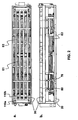
- Fig. 1 shows the lashing platform according to the invention in a particularly preferred embodiment in a perspective view.
- the lashing platform 10 consists of a base frame 20 and a resiliently mounted thereon Absetzplatte 30.
- the Absetzplatte 30 has on its upper side in the region of their end faces so-called Einweiser 110a, 110b, wherein the inner Einweiser 110b retractable in the settling plate, z. B. fold away, are set up.
- the instructors serve to "instruct" the container or containers in a predetermined position in which the container fittings can be approached by the units or their screwing devices arranged thereunder.
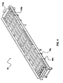
- the in Fig. 3 shown base frame 20 is connected to the in Fig. 4 shown Absetzplatte 30 via pumping cylinder 70 and lifting cylinder 80 (reference numeral 70a and 80a indicate the arranged on the Absetzplatte 30 abutment of the pump or lifting cylinder 70, 80).
- the pump cylinders 70 are used to generate energy when the container settles on the settling plate 30 and the subsequent lowering of the settling plate 30 onto the base frame 20.
- the lifting cylinders 80 serve to reposition the settling plate 30 after the container has been removed from the settling plate 30 to bring in the starting position in which again a container can be discontinued.
- the pump cylinders 70 for storing the compressed gas via a respective line with at least one gas storage device 90, wherein the gas storage device 90 is particularly preferably connected to operate the drive for moving the units via at least one line to the drive of the units.
- a pump cylinder control acting on the pump cylinder is preferably provided, which enables a uniform lowering of a container in the longitudinal direction of the lashing platform 10. This is done by a valve control enforcing a uniform pressure increase in all cylinders. Particularly preferably, the valve control ensures that the pump cylinders, which are opposite one another in the longitudinal direction, uniformly lower, so that tilting of the settling plate 30 relative to the base frame 20 in the longitudinal direction of the lashing platform 10 can be prevented.
- FIG. 2 How out Fig. 2 can be seen, between the base frame 20 and settling plate 30 in the example shown 2 in the longitudinal direction against each other movable units E1, E2 arranged.
- FIG. 5 can be seen, preferably from four arranged at their corners screwing, each one arranged on its front side transfer device 50a, 50b and each one of a transfer device 50a, 50b arranged magazine 60th
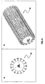
- the magazine 60 shown is preferably formed as a drum, wherein the drum has rails mounted in the longitudinal direction of the drum, which form a plurality of extending in the longitudinal direction of the drum spaces in which the twist locks can be accommodated. For this purpose, the twistlocks are pushed in their closed position on the rails, so that they are stored in the magazine 60 hanging.
- the magazine 60 clamping rails which store the twist locks in predetermined positions clamping.
- the clamping rails are made of an elastic material for this purpose, but may additionally or alternatively also be resiliently mounted.
- the lateral boundaries of the drum have radially extending bulges, so that the twistlocks can be pushed laterally into the magazine.
- Fig. 7 shows the transport device 50a of the transfer device 50, with which the twist locks are transported by the screw 40 in the magazine 60 and the magazine 60 in the screw 40.
- the transport device 50a is moved after removal of a twistlock from a container to the screw 40, wherein the legs of the U-shaped protrusion of the transport device 50a are positioned adjacent the twistlock. Then the twistlock is locked again, so that the transport device 50a can lift the twistlock out of the screw 40.
- the twistlock is then guided to the upper lateral bulge of the magazine and pushed into the magazine 60 with the aid of the rake 50b shown below, which is part of the transfer device 50.
- a twistlock is transferred from the magazine 60 in the U-shaped bulge of the transport device 50a by the rake 50b, whereupon this twist lock in the Screwing 40 sets.
- the screw 40 unlocks the twistlock, after which the conveyor 50a is free again and can return to its waiting position.
- the rake 50b preferably has a plurality of prongs, which are spaced apart from one another at the spacing of the spaces between the bearing positions of the twistlocks arranged in the magazine 60. It is thereby achieved that not only a twistlock is pushed into or out of the magazine 60, but that all twistlocks which are suspended in the magazine 60 between two rails are inserted into the magazine 60 or removed from the magazine 60 are moved simultaneously - so the rake 50b is always moved only by one position of a twistlock storage bin. This avoids that the twistlocks get caught and / or damaged.
- the prongs of the rake 50b are tapered at their end.
- the insertion of the rake 50b is facilitated in the interstices of the magazine, in addition with a training of the magazine 60 with clamping rails a pressing apart of the clamping rails is achieved, whereby the twist locks are easier to move during loading or unloading of the corresponding clamping rails, as the clamping rails be pushed apart by inserting the prongs of the rake 50b.
- magazine 60 in its embodiment shown here can also be used in conventional lashing platforms, without it being necessary for the special design of the lashing platform 10 shown here.
- the lashing platform 10 preferably has a sensor acting on the controller for moving the units E1, E2 to detect the size of a container to be deposited or set down on the lashing platform.
- the control additionally or alternatively detects the number of containers to be dropped or set down on the lashing platform.
Description
Die Erfindung betrifft eine Laschplattform mit einem Grundrahmen, einer auf dem Grundrahmen federnd gelagerten Absetzplatte, einer Mehrzahl von Schraubeinrichtungen zum Einsetzen von Twistlocks in Containerbeschläge bzw. Entnehmen von Twistlocks aus Containerbeschlägen, einer Mehrzahl von Magazinen zur Aufnahme der Twistlocks und einer Mehrzahl von Übergabeeinrichtungen zur Übergabe eines Twistlocks von einem Magazin an eine Schraubeinrichtung bzw. von einer Schraubeinrichtung an ein Magazin.The invention relates to a lashing platform with a base frame, a resiliently mounted on the base frame settling plate, a plurality of screw means for inserting twist locks in container fittings or removal of twist locks from container fittings, a plurality of magazines for receiving the twist locks and a plurality of transfer devices for transfer a twistlock from a magazine to a screw or from a screw to a magazine.
Laschplattformen sind in verschiedenen Ausführungen bekannt. Diese weisen eine Absetzplatte zur Aufnahme eines oder mehrerer Container und verschiedenartig ausgestaltete Schraubeinrichtungen zum Abnehmen von Twistlocks aus den Containerbeschlägen bzw. zum Einsetzen von Twistlocks in die Containerbeschläge auf.Lashing platforms are known in various designs. These have a Absetzplatte for receiving one or more containers and variously configured screw means for removing Twistlocks from the container fittings or for inserting twist locks in the container fittings.
Der Vorteil einer Laschplattform besteht darin, dass die ansonsten manuell durchgeführte Tätigkeit des Einsetzens bzw. Herausnehmens der Twistlocks, die zur Vermeidung von Unfällen erheblicher Sicherheitsanforderungen bedarf, automatisch durchgeführt wird, wobei sich das Personal nicht im Gefahrenbereich des Containers befindet und daher geringere Sicherheitsanforderungen herrschen. Der Umschlag der Container kann damit in kürzerer Zeit erfolgen.The advantage of a lashing platform is that the otherwise manually performed operation of inserting or removing the twistlocks, which requires considerable safety requirements to avoid accidents, is carried out automatically, whereby the personnel are not in the danger zone of the container and therefore have lower safety requirements. The envelope of the container can thus be done in less time.
Eine besonders vorteilhaft ausgestaltete Laschplattform ist beispielsweise aus der
Die aus der
Insbesondere wird in der
Nachteilig an dieser Plattform ist jedoch, dass Container anderer Größen, z.B. ein 45'Container, nicht von dieser Laschplattform aufgenommen bzw. mit dieser bearbeitet werden können.However, a disadvantage of this platform is that containers of other sizes, e.g. a 45'Container, can not be taken up by this Laschplattform or edited with this.
Dagegen ist von der Firma RAM (Singapur) die Laschplattform RAM 4000 zur Aufnahme eines 20' Containers, zwei 20'Container im Twinbetrieb und einem 40'Container bekannt, wobei sich darüber hinaus auch ein 45'Container auf der Laschplattform absetzen lässt. Mit dieser bekannten Laschplattform können also die gängigsten Containergrößen umgeschlagen werden.By contrast, RAM (Singapore) uses the RAM 4000 ram platform to hold a 20 'container, two 20' containers in twin operation and a 40 'container, whereby a 45' container can also be placed on the lashing platform. With this known lashing platform so the most common container sizes can be handled.
An dieser Lösung nachteilig ist jedoch, dass ein 45' Container lediglich auf der Plattform abgesetzt werden kann, jedoch nicht automatisch von den Twistlocks entbunden bzw. mit diesen versehen werden kann. Vielmehr ragt ein 45' Container über die Abmessungen dieser bekannten Laschplattformen hinaus, so dass die Twistlocks weiterhin manuell aus den Containerbeschlägen entnommen bzw. in diese eingesetzt werden müssen. Dadurch entsteht wiederum eine potentiell gefahrenträchtige Arbeitssituation für das Laschpersonal.A disadvantage of this solution, however, is that a 45 'container can only be placed on the platform, but not automatically released from the twistlocks or can be provided with them. Rather, a 45 'container projects beyond the dimensions of these known lashing platforms, so that the twistlocks must continue to be manually removed from the container fittings or inserted into them. This in turn creates a potentially hazardous working situation for the lashing staff.
Darüber hinaus sind die 45'Container auch nur unzureichend auf der Laschplattform, nämlich nur an ihren Längsseiten, gesichert, wobei auch das Hinauskragen über die Laschplattform problematisch unter Sicherheitgesichtspunkten, z.B. für den Verkehr am Kai, problematisch erscheint.Moreover, the 45 'containers are also insufficiently secured on the lashing platform, namely only on their longitudinal sides, whereby even protruding over the lashing platform is problematic from a safety point of view, e.g. for traffic on the quayside, seems problematic.
Zwar ist aus der
Aufgabe der Erfindung ist es daher, eine Laschplattform bereitzustellen, mit der verschiedene Containergrößen, auch im Twinbetrieb, automatisch umgeschlagen, d.h. für den Transport vorbereitet werden können. Insbesondere soll das Herausnehmen bzw. das Einsetzen von Twinlocks in die Beschläge der Container automatisch erfolgen, ohne dass sich Personal in der unmittelbaren Umgebung des Containers befinden muss bzw. ohne dass die Laschplattform ein Sicherheitsrisiko für das am Boden arbeitende Personal darstellt.The object of the invention is therefore to provide a lashing platform, with the various container sizes, even in twin operation, automatically handled, ie for transport can be prepared. In particular, the removal or the insertion of Twinlocks in the fittings of the container should be done automatically, without having to be in the immediate vicinity of the container or without the lashing platform is a security risk for working on the ground staff.
Die Aufgabe wird erfindungsgemäß durch die Laschplattform mit den Merkmalen von Anspruch 1 gelöst. Die Unteransprüche geben vorteilhafte Ausgestaltungen der Erfindung wieder.The object is achieved by the lashing platform with the features of claim 1. The subclaims reflect advantageous embodiments of the invention.
Grundgedanke der Erfindung ist es, wenigstens zwei aus je wenigstens zwei Schraubeinrichtungen, wenigstens einer Übergabeeinrichtung und wenigstens einem Magazin gebildeten Einheiten vorzusehen, die in Längsrichtung der Laschplattform innerhalb des Grundrahmens gegeneinander verfahrbar sind. Hierfür ist der Grundrahmen bereits für die Aufnahme einer maximalen Containergröße, z.B. einem 45' Container eingerichtet, ohne dass der Container über die Grundfläche der Laschplattform hinauskragt.The basic idea of the invention is to provide at least two units each consisting of at least two screw devices, at least one transfer device and at least one magazine, which units can be moved relative to one another in the longitudinal direction of the lashing platform within the base frame. For this, the base frame is already for receiving a maximum container size, e.g. a 45 'container without the container protruding beyond the base of the lashing platform.
Durch die Verfahrbarkeit innerhalb des Grundrahmens ist es ermöglicht, die Laschplattform an verschiedene Containergrößen anzupassen. Insbesondere wird durch das Verfahren der Einheiten dafür gesorgt, dass die Schraubeinrichtungen zu den jeweils von der Containergröße abhängigen Position der Containerbeschläge, die regelmäßig als Eckbeschläge ausgebildet sind, zu verbringen. Hierzu sind wenigstens ein Antrieb zum Verfahren der Einheiten, sowie eine auf den Antrieb wirkende Steuerung vorgesehen.The mobility within the base frame makes it possible to adapt the lashing platform to different container sizes. In particular, it is ensured by the method of the units that the screw means to spend each dependent on the container size position of the container fittings, which are regularly formed as corner fittings. For this purpose, at least one drive for moving the units and a control acting on the drive are provided.
Insbesondere soll durch das steuerbare Verfahren der Einheit erreicht werden, dass die Einheiten zueinander derart zueinander angeordnet werden können, dass die Schraubeinrichtungen der Einheiten Zugriff auf die Containerbeschläge von einem 20' Container, von zwei 20' Containern im Twinbetrieb, einem 40' Container oder einem 45' Container haben.In particular, should be achieved by the controllable method of the unit that the units to each other can be arranged such that the screwing units of the units access to the container fittings of a 20 'container, two 20' containers in twin operation, a 40 'container or a 45 'containers have.
Dadurch, dass äußerlich keine Größenänderung der Laschplattform erfolgt, kann eine sichere Aufstellung der Laschplattform erfolgen, ohne dass das im Laschbetrieb arbeitende Personal von plötzlichen Größenänderungen der Laschplattform oder überkragenden Containern überrascht wird. Die Arbeit mit Containern wird dadurch noch sicherer.Due to the fact that no change in size of the lashing platform takes place externally, a secure installation of the lashing platform can take place without the staff working in lashing being surprised by sudden changes in size of the lashing platform or overhanging containers. Working with containers will be even safer.
Die Erfindung wird anhand eines in den Zeichnungen dargestellten besonders bevorzugten Ausführungsbeispiels näher erläutert. Es zeigen:
- Fig. 1
- eine perspektivische Ansicht der Laschplattform nach der Erfindung;
- Fig. 2
- eine Drauf- (a) und eine Seitenansicht (b) der Laschplattform aus
Fig. 1 ; - Fig. 3
- eine perspektivische Ansicht des Grundrahmens der Laschplattform aus
Fig. 1 ; - Fig. 4
- eine schematische, perspektivische Ansicht der Absetzplatte der Laschplattform aus
Fig. 1 ; - Fig. 5
- eine perspektivische Ansicht einer aus Schraubeinrichtungen, Übergabeeinrichtung und Magazin gebildeten Einheit der Laschplattform aus
Fig. 1 ; - Fig. 6
- eine Seitenansicht (a) und eine perspektivische Ansicht (b) des Magazins der Laschplattform aus
Fig. 1 ; - Fig. 7
- eine perspektivische Ansicht eines die Übergabeeinrichtung bildenden ersten Bauteils, nämlich der Transporteinrichtung; und
- Fig. 8
- eine perspektivische Ansicht eines die Übergabeeinrichtung bildenden zweiten Bauteils, nämlich des Rechens.
- Fig. 1
- a perspective view of the lashing platform according to the invention;
- Fig. 2
- a top (a) and a side view (b) of the lashing platform
Fig. 1 ; - Fig. 3
- a perspective view of the base frame of the lashing platform
Fig. 1 ; - Fig. 4
- a schematic, perspective view of the settling plate of the lashing platform
Fig. 1 ; - Fig. 5
- a perspective view of a unit formed by screwing, transfer device and magazine of the lashing platform
Fig. 1 ; - Fig. 6
- a side view (a) and a perspective view (b) of the magazine of the lashing platform
Fig. 1 ; - Fig. 7
- a perspective view of the transfer device forming the first component, namely the transport device; and
- Fig. 8
- a perspective view of the transfer device forming the second component, namely the rake.
Der in
Bevorzugt sind die Pumpzylinder 70 zur Speicherung des komprimierten Gases über jeweils eine Leitung mit wenigstens einer Gasspeichereinrichtung 90 verbunden, wobei die Gasspeichereinrichtung 90 besonders bevorzugt zum Betrieb des Antriebs zum Verfahren der Einheiten über wenigstens eine Leitung mit dem Antrieb der Einheiten verbunden ist.Preferably, the
Darüber hinaus ist bevorzugt eine auf die Pumpzylinder wirkende Pumpzylindersteuerung vorgesehen, die ein gleichmäßiges Absenken eines Containers in Längsrichtung der Laschplattform 10 ermöglicht. Dieses erfolgt dadurch, dass eine Ventilsteuerung eine gleichmäßige Druckerhöhung in allen Zylindern erzwingt. Besonders bevorzugt sorgt die Ventilsteuerung dafür, dass die sich in Längsrichtung gegenüberliegenden Pumpzylinder gleichmäßig absenken, damit ein Verkippen der Absetzplatte 30 im Verhältnis zum Grundrahmen 20 in Längsrichtung der Laschplattform 10 verhindert werden kann.In addition, a pump cylinder control acting on the pump cylinder is preferably provided, which enables a uniform lowering of a container in the longitudinal direction of the
Um ein Verkippen der Absetzplatte 30 im Verhältnis zum Grundrahmen 20 in Querrichtung der Laschplattform 10 zu unterbinden, ist vorgesehen, dass sich an den beiden Stirnseiten der Laschplattform 10 angeordnete Gleichlaufsysteme 100 befinden (siehe
Wie aus
Diese bestehen jeweils, wie aus
Das in
Bevorzugt weist das Magazin 60 Klemmschienen auf, die die Twistlocks in vorbestimmten Positionen festklemmend lagern. Die Klemmschienen sind hierfür aus einem elastischen Material gefertigt, können aber zusätzlich oder alternativ auch federnd gelagert sein. Besonders bevorzugt weisen die Klemmschienen zwischen den zur Lagerung der Twistlocks vorbestimmten Positionen die Positionen begrenzende Erhebungen auf, so dass die Twistlocks an einem seitlichen Verschieben gehindert sind.Preferably, the
Zum Einschieben der Twistlocks in das Magazin 60 weisen die seitlichen Begrenzungen der Trommel radial verlaufende Ausbuchtungen auf, sodass die Twistlocks seitlich in das Magazin geschoben werden können.To insert the twistlocks into the
Die Transporteinrichtung 50a wird nach Entnahme eines Twistlocks aus einem Container zur Schraubeinrichtung 40 bewegt, wobei die Schenkel der U-förmigen Ausbuchtung der Transporteinrichtung 50a den Twistlock benachbart positioniert werden. Darauf wird der Twistlock wieder verriegelt, sodass die Transporteinrichtung 50a den Twistlock aus der Schraubeinrichtung 40 herausheben kann.The
Der Twistlock wird dann zur oberen seitlichen Ausbuchtung des Magazins geführt und mit Hilfe des im Folgenden dargestellten Rechen 50b, der Teil der Übergabeeinrichtung 50 ist, in das Magazin 60 geschoben.The twistlock is then guided to the upper lateral bulge of the magazine and pushed into the
Umgekehrt wird durch den Rechen 50b ein Twistlock aus dem Magazin 60 in die U-förmige Ausbuchtung der Transporteinrichtung 50a überführt, worauf diese den Twistlock in die Schraubeinrichtung 40 setzt. Die Schraubeinrichtung 40 entriegelt den Twistlock, wonach die Transporteinrichtung 50a wieder frei wird und in ihre Warteposition zurückfahren kann.Conversely, a twistlock is transferred from the
Die Übergabe der Twistlocks von der Transporteinrichtung 50a in das Magazin 60 erfolgt, wie vorher beschrieben, durch den in
Besonders bevorzugt sind die Zinken des Rechen 50b an ihrem Ende sich verjüngend ausgebildet. Damit wird einerseits das Einführen des Rechen 50b in die Zwischenräume des Magazins erleichtert, wobei zusätzlich bei einer Ausbildung des Magazins 60 mit Klemmschienen ein Auseinanderdrücken der Klemmschienen erreicht wird, wodurch die Twistlocks beim Beladen bzw. Entladen der entsprechenden Klemmschienen leichter beweglich sind, da die Klemmschienen durch Einführen der Zinken des Rechens 50b auseinandergedrückt werden.Particularly preferably, the prongs of the
Es versteht sich, dass das Magazin 60 in seiner hier dargestellten Ausgestaltung auch in herkömmlichen Laschplattformen Verwendung finden kann, ohne dass es auf die spezielle Ausgestaltung der hier dargestellten Laschplattform 10 ankäme.It is understood that the
Schließlich weist die Laschplattform 10 bevorzugt eine auf die Steuerung zum Verfahren der Einheiten E1, E2 wirkende Sensorik zum Erfassen der Größe eines auf die Laschplattform abzusetzenden oder abgesetzten Containers auf. Dabei erfasst die Steuerung zusätzlich oder alternativ die Anzahl der auf die Laschplattform abzusetzenden oder abgesetzten Container.Finally, the
Weiterhin kann auch vorgesehen sein, dass von der Größe des Containers auf das Gewicht des Containers zurückgeschlossen wird, um entsprechende Voreinstellungen bezüglich der zu erwartenden zu gewinnenden Energie bzw. des Austarierens des Containers auf der Laschplattform vornehmen zu können.Furthermore, it can also be provided that it is deduced from the size of the container on the weight of the container to corresponding presets with respect to expected to gain energy or the Austarierens of the container on the lashing platform to make.
Claims (15)
- A lashing platform (10) comprising a base frame (20), a setting plate (30) resiliently supported on the base frame (20), a plurality of screwing devices (40) for inserting twistlocks into container fittings or removing twistlocks from container fittings, a plurality of magazines (60) for accommodating the twistlocks, and a plurality of transfer devices (50a, 50b) for transferring a twistlock from a magazine (60) to a screwing device (40) or from a screwing device (40) to a magazine (60),
characterized by
at least two units (E1, E2), which are each formed by at least two screwing devices (40), at least one transfer device (50a, 50b), and at least one magazine (60) and which can be moved relative to each other in the longitudinal direction of the lashing platform (10) within the base frame (20),
at least one drive for moving the units (E1, E2), and
a controller for moving the units (E1, E2) into positions in which the screwing devices (40) have access to the container fittings of containers of different size. - The lashing platform (10) according to Claim 1, characterized by positions, that can be moved to, for a 20' container, two 20' containers, a 40' container or a 45' container.
- The lashing platform (10) according to one of the preceding claims, characterized in that the units (E1, E2) are in each case formed from four screwing units (40), two transfer devices (50a, 50b), and a magazine (60).
- The lashing platform (10) according to one of the preceding claims, characterized by pump cylinders (70) that are arranged at the long sides of the lashing platform (10), connect the base frame (20) to the setting plate (30) and that are connected via at least one line to at least one gas-storage device (90) so as to store the compressed gas.
- The lashing platform (10) according to Claim 4, characterized in that the drive of the units (E1, E2) is operated by means of energy provided from the gas-storage device (90).
- The lashing platform (10) according to one of Claims 4 or 5, characterized by a pump-cylinder control acting on the pump cylinders (70) for uniformly lowering a container.
- The lashing platform (10) according to Claim 6, characterized in that the pump-cylinder control is designed to prevent the setting plate (30) from tilting in the longitudinal direction of the lashing platform (10) relative to the base frame (20).
- The lashing platform (10) according to one of the preceding claims, characterized by hydraulic lifting cylinders (80) for lifting the setting plate (30) into the starting position, that are arranged on the long sides of the lashing platform (10) and connect the base frame (20) to the setting plate (30).
- The lashing platform (10) according to one of the preceding claims, characterized by synchronizing systems (100) arranged on both end faces for preventing the setting plate (30) from tilting in the transverse direction of the lashing platform (10) relative to the base frame (20).
- The lashing platform (10) according to one of the preceding claims, characterized by sensors acting on the control for detecting the size of a container that is to be set down or has been set down on the lashing platform (10).
- The lashing platform (10) according to one of the preceding claims, characterized by sensors acting on the control for detecting the number of containers that are to be set down or have been set down on the lashing platform (10).
- The lashing platform (10) according to one of the preceding claims, characterized in that the transfer device (50a, 50b) is formed from a transportation device (50a) for transporting a twistlock from a screwing device (40) to the magazine (60) or from the magazine (60) to the screwing device (40) and a rake (50b) that pushes the twistlock from the transportation device (50a) into the magazine (60) or a rake (50b) that pushes the twistlock from the magazine (60) into the transportation device (50a).
- The lashing platform (10) according to Claim 12, characterized in that the rake (50b) exhibits a plurality of tines that are spaced from each other with the spacing of the intervals between the storage positions of the twistlocks, set up in the magazine (60).
- The lashing platform (10) according to Claim 12 or 13, characterized in that the tines of the rake (50b) are designed such that they taper at their free ends.
- The lashing platform (10) according to one of the preceding claims, characterized in that the magazine (60) is designed as a drum.
Priority Applications (1)
| Application Number | Priority Date | Filing Date | Title |
|---|---|---|---|
| PL10732621T PL2448844T3 (en) | 2009-06-30 | 2010-05-26 | Lashing platform having a magazine for twistlocks |
Applications Claiming Priority (2)
| Application Number | Priority Date | Filing Date | Title |
|---|---|---|---|
| DE102009031272A DE102009031272B3 (en) | 2009-06-30 | 2009-06-30 | Lashing platform with magazine for twistlocks |
| PCT/DE2010/000575 WO2011000336A1 (en) | 2009-06-30 | 2010-05-26 | Lashing platform having a magazine for twistlocks |
Publications (2)
| Publication Number | Publication Date |
|---|---|
| EP2448844A1 EP2448844A1 (en) | 2012-05-09 |
| EP2448844B1 true EP2448844B1 (en) | 2015-01-14 |
Family
ID=42634953
Family Applications (1)
| Application Number | Title | Priority Date | Filing Date |
|---|---|---|---|
| EP10732621.7A Active EP2448844B1 (en) | 2009-06-30 | 2010-05-26 | Lashing platform having a magazine for twistlocks |
Country Status (12)
| Country | Link |
|---|---|
| US (1) | US8661658B2 (en) |
| EP (1) | EP2448844B1 (en) |
| AU (1) | AU2010268517B2 (en) |
| DE (1) | DE102009031272B3 (en) |
| DK (1) | DK2448844T3 (en) |
| ES (1) | ES2531416T3 (en) |
| NZ (1) | NZ597726A (en) |
| PL (1) | PL2448844T3 (en) |
| PT (1) | PT2448844E (en) |
| SG (1) | SG178168A1 (en) |
| WO (1) | WO2011000336A1 (en) |
| ZA (1) | ZA201200197B (en) |
Families Citing this family (6)
| Publication number | Priority date | Publication date | Assignee | Title |
|---|---|---|---|---|
| DE102009020999A1 (en) * | 2009-05-12 | 2010-11-18 | Hydac System Gmbh | lashing platform |
| DE102011016369B3 (en) | 2011-04-07 | 2012-09-13 | Rainer Kapelski | Assembly machine for a lashing platform |
| EP3924287A1 (en) * | 2019-02-13 | 2021-12-22 | Blok Container Systems Limited | Rig, corner unit |
| CN113811496A (en) | 2019-03-29 | 2021-12-17 | 冉斯玛格起重技术私人有限公司 | Method and apparatus for twist lock handling and management |
| CN115258057A (en) * | 2022-06-15 | 2022-11-01 | 中船澄西船舶修造有限公司 | Button lock box layout structure of refrigeration centralized box ship |
| CN116274504A (en) * | 2023-04-03 | 2023-06-23 | 南京艾曼达船舶设备制造有限公司 | Container ligature pole coalignment |
Family Cites Families (8)
| Publication number | Priority date | Publication date | Assignee | Title |
|---|---|---|---|---|
| DE4317996A1 (en) * | 1993-05-28 | 1994-12-01 | Tax Ingenieurgesellschaft Mbh | Process and device for moving containers Keyword: Cradle |
| NL1012849C2 (en) * | 1999-08-18 | 2001-02-20 | Univ Delft Tech | Method and device for applying or removing a semi-automatic twist lock. |
| US6554557B1 (en) * | 2002-02-04 | 2003-04-29 | Paceco Corp. | Inter-box connector (IBC) installation and removal system |
| US20060115350A1 (en) * | 2003-01-15 | 2006-06-01 | Otto Weis | Device for automatically installing and reoving twistlocks |
| DE10301197A1 (en) * | 2003-01-15 | 2004-08-19 | Noell Crane Systems Gmbh | Device for the automatic removal and installation of twistlocks |
| KR101222365B1 (en) * | 2004-08-30 | 2013-01-15 | 엔에스엘 엔지니어링 피티이 리미티드 | Twist-lock handling system |
| AU2005335498A1 (en) * | 2005-08-16 | 2007-02-22 | Sunrose Tecdesign Pte Ltd. | Inter-box connector (IBC) storage and handling system |
| DE102006015807A1 (en) * | 2006-03-02 | 2007-09-06 | Rainer Kapelski | Device and method for inserting and removing twist-lock container securing fittings |
-
2009
- 2009-06-30 DE DE102009031272A patent/DE102009031272B3/en not_active Expired - Fee Related
-
2010
- 2010-05-26 US US13/381,443 patent/US8661658B2/en active Active
- 2010-05-26 WO PCT/DE2010/000575 patent/WO2011000336A1/en active Application Filing
- 2010-05-26 NZ NZ597726A patent/NZ597726A/en not_active IP Right Cessation
- 2010-05-26 PL PL10732621T patent/PL2448844T3/en unknown
- 2010-05-26 ES ES10732621T patent/ES2531416T3/en active Active
- 2010-05-26 EP EP10732621.7A patent/EP2448844B1/en active Active
- 2010-05-26 AU AU2010268517A patent/AU2010268517B2/en active Active
- 2010-05-26 DK DK10732621T patent/DK2448844T3/en active
- 2010-05-26 PT PT107326217T patent/PT2448844E/en unknown
- 2010-05-26 SG SG2012006508A patent/SG178168A1/en unknown
-
2012
- 2012-01-10 ZA ZA2012/00197A patent/ZA201200197B/en unknown
Also Published As
| Publication number | Publication date |
|---|---|
| DE102009031272B3 (en) | 2010-12-30 |
| SG178168A1 (en) | 2012-03-29 |
| DK2448844T3 (en) | 2015-04-27 |
| AU2010268517B2 (en) | 2016-05-12 |
| PT2448844E (en) | 2015-03-30 |
| WO2011000336A1 (en) | 2011-01-06 |
| US8661658B2 (en) | 2014-03-04 |
| AU2010268517A1 (en) | 2012-02-16 |
| PL2448844T3 (en) | 2015-08-31 |
| NZ597726A (en) | 2012-12-21 |
| ZA201200197B (en) | 2012-09-26 |
| EP2448844A1 (en) | 2012-05-09 |
| ES2531416T3 (en) | 2015-03-13 |
| US20120167382A1 (en) | 2012-07-05 |
Similar Documents
| Publication | Publication Date | Title |
|---|---|---|
| EP2448844B1 (en) | Lashing platform having a magazine for twistlocks | |
| EP1999040A1 (en) | Device and method for inserting and removing securing fittings for twist-lock containers | |
| EP1585690B1 (en) | Device for automatically mounting or removing twistlocks | |
| WO2020182699A1 (en) | Storage and retrieval unit for loading stackable goods, and logistics system having such a storage and retrieval unit | |
| DE102008061204B3 (en) | Magazine for storing twist locks | |
| EP2261129B1 (en) | Palette for transporting objects using a forklift | |
| DE102006002384B4 (en) | Method and device for securing cargo | |
| DE102017114643A1 (en) | Storage and retrieval machine suitable for use in a high-bay warehouse | |
| DE102009040792A1 (en) | Pallet stack manipulator for unstacking device for scheduling pallet stack with pallets nested with each other for unstacking, has centering device to center two pallets of pallet stack to each other | |
| DE102004004146B3 (en) | Apparatus and method for securing stacked objects | |
| WO2014048966A2 (en) | Stackable bundle of compressed gas cylinders | |
| DE19514536A1 (en) | Support and transport frame for standard containers | |
| DE3337126A1 (en) | DEVICE FOR DELIVERING AND / OR RECEIVING PANELS, ESPECIALLY CIRCUIT BOARDS, FROM OR IN A PACK OF DISKS | |
| DE1531172A1 (en) | Double lifting traverse for the optional handling of two 20-foot large containers or a single 40-foot large container | |
| DE102013001484B3 (en) | Transport pallet for compressed gas cylinders | |
| DE102011016369B3 (en) | Assembly machine for a lashing platform | |
| EP2885218B1 (en) | Storage device for storing a container unit, system and installation for storing container units | |
| DE10234310A1 (en) | Loading plant esp. for handling of palettes and containers, for cargo ships has associated satellite vehicle, e.g. transport and handling gate, driven onto loading platform, with rollers for containers | |
| EP1329400A2 (en) | Turning station for transport containers | |
| WO2019073462A1 (en) | Underground collection device for waste | |
| DE102018100734A1 (en) | Dolly loading | |
| DE2543517A1 (en) | Container pallet loading rig - has roller tracks with grooves and recesses fitting frame with stays | |
| DE7516654U (en) | Device for loading and unloading containers and swap bodies with piece goods | |
| Hennings et al. | Arrangement for storage of heat-dissipating spent fuel elements enclosed in containers | |
| DE10303469A1 (en) | Arrangement for shifting, transporting roll-off containers, especially for waste, in ships' hold has lifting arrangement in hold with flat platform(s) for at least two containers, lifting pillars, drive |
Legal Events
| Date | Code | Title | Description |
|---|---|---|---|
| PUAI | Public reference made under article 153(3) epc to a published international application that has entered the european phase |
Free format text: ORIGINAL CODE: 0009012 |
|
| 17P | Request for examination filed |
Effective date: 20111229 |
|
| AK | Designated contracting states |
Kind code of ref document: A1 Designated state(s): AL AT BE BG CH CY CZ DE DK EE ES FI FR GB GR HR HU IE IS IT LI LT LU LV MC MK MT NL NO PL PT RO SE SI SK SM TR |
|
| DAX | Request for extension of the european patent (deleted) | ||
| RAP1 | Party data changed (applicant data changed or rights of an application transferred) |
Owner name: KALP GMBH |
|
| RIN1 | Information on inventor provided before grant (corrected) |
Inventor name: KAPELSKI, RAINER |
|
| 17Q | First examination report despatched |
Effective date: 20140516 |
|
| GRAP | Despatch of communication of intention to grant a patent |
Free format text: ORIGINAL CODE: EPIDOSNIGR1 |
|
| INTG | Intention to grant announced |
Effective date: 20141030 |
|
| GRAS | Grant fee paid |
Free format text: ORIGINAL CODE: EPIDOSNIGR3 |
|
| GRAA | (expected) grant |
Free format text: ORIGINAL CODE: 0009210 |
|
| AK | Designated contracting states |
Kind code of ref document: B1 Designated state(s): AL AT BE BG CH CY CZ DE DK EE ES FI FR GB GR HR HU IE IS IT LI LT LU LV MC MK MT NL NO PL PT RO SE SI SK SM TR |
|
| REG | Reference to a national code |
Ref country code: GB Ref legal event code: FG4D Free format text: NOT ENGLISH |
|
| REG | Reference to a national code |
Ref country code: CH Ref legal event code: EP |
|
| REG | Reference to a national code |
Ref country code: IE Ref legal event code: FG4D Free format text: LANGUAGE OF EP DOCUMENT: GERMAN |
|
| REG | Reference to a national code |
Ref country code: AT Ref legal event code: REF Ref document number: 706906 Country of ref document: AT Kind code of ref document: T Effective date: 20150215 |
|
| REG | Reference to a national code |
Ref country code: DE Ref legal event code: R096 Ref document number: 502010008738 Country of ref document: DE Effective date: 20150226 |
|
| REG | Reference to a national code |
Ref country code: ES Ref legal event code: FG2A Ref document number: 2531416 Country of ref document: ES Kind code of ref document: T3 Effective date: 20150313 |
|
| REG | Reference to a national code |
Ref country code: PT Ref legal event code: SC4A Free format text: AVAILABILITY OF NATIONAL TRANSLATION Effective date: 20150316 |
|
| REG | Reference to a national code |
Ref country code: DK Ref legal event code: T3 Effective date: 20150421 |
|
| REG | Reference to a national code |
Ref country code: SE Ref legal event code: TRGR |
|
| REG | Reference to a national code |
Ref country code: NL Ref legal event code: T3 |
|
| REG | Reference to a national code |
Ref country code: LT Ref legal event code: MG4D |
|
| PG25 | Lapsed in a contracting state [announced via postgrant information from national office to epo] |
Ref country code: BG Free format text: LAPSE BECAUSE OF FAILURE TO SUBMIT A TRANSLATION OF THE DESCRIPTION OR TO PAY THE FEE WITHIN THE PRESCRIBED TIME-LIMIT Effective date: 20150414 Ref country code: NO Free format text: LAPSE BECAUSE OF FAILURE TO SUBMIT A TRANSLATION OF THE DESCRIPTION OR TO PAY THE FEE WITHIN THE PRESCRIBED TIME-LIMIT Effective date: 20150414 Ref country code: LT Free format text: LAPSE BECAUSE OF FAILURE TO SUBMIT A TRANSLATION OF THE DESCRIPTION OR TO PAY THE FEE WITHIN THE PRESCRIBED TIME-LIMIT Effective date: 20150114 Ref country code: HR Free format text: LAPSE BECAUSE OF FAILURE TO SUBMIT A TRANSLATION OF THE DESCRIPTION OR TO PAY THE FEE WITHIN THE PRESCRIBED TIME-LIMIT Effective date: 20150114 |
|
| PG25 | Lapsed in a contracting state [announced via postgrant information from national office to epo] |
Ref country code: IS Free format text: LAPSE BECAUSE OF FAILURE TO SUBMIT A TRANSLATION OF THE DESCRIPTION OR TO PAY THE FEE WITHIN THE PRESCRIBED TIME-LIMIT Effective date: 20150514 Ref country code: LV Free format text: LAPSE BECAUSE OF FAILURE TO SUBMIT A TRANSLATION OF THE DESCRIPTION OR TO PAY THE FEE WITHIN THE PRESCRIBED TIME-LIMIT Effective date: 20150114 Ref country code: GR Free format text: LAPSE BECAUSE OF FAILURE TO SUBMIT A TRANSLATION OF THE DESCRIPTION OR TO PAY THE FEE WITHIN THE PRESCRIBED TIME-LIMIT Effective date: 20150415 |
|
| REG | Reference to a national code |
Ref country code: PL Ref legal event code: T3 |
|
| REG | Reference to a national code |
Ref country code: DE Ref legal event code: R097 Ref document number: 502010008738 Country of ref document: DE |
|
| PG25 | Lapsed in a contracting state [announced via postgrant information from national office to epo] |
Ref country code: SK Free format text: LAPSE BECAUSE OF FAILURE TO SUBMIT A TRANSLATION OF THE DESCRIPTION OR TO PAY THE FEE WITHIN THE PRESCRIBED TIME-LIMIT Effective date: 20150114 Ref country code: EE Free format text: LAPSE BECAUSE OF FAILURE TO SUBMIT A TRANSLATION OF THE DESCRIPTION OR TO PAY THE FEE WITHIN THE PRESCRIBED TIME-LIMIT Effective date: 20150114 Ref country code: CZ Free format text: LAPSE BECAUSE OF FAILURE TO SUBMIT A TRANSLATION OF THE DESCRIPTION OR TO PAY THE FEE WITHIN THE PRESCRIBED TIME-LIMIT Effective date: 20150114 Ref country code: RO Free format text: LAPSE BECAUSE OF FAILURE TO SUBMIT A TRANSLATION OF THE DESCRIPTION OR TO PAY THE FEE WITHIN THE PRESCRIBED TIME-LIMIT Effective date: 20150114 |
|
| PLBE | No opposition filed within time limit |
Free format text: ORIGINAL CODE: 0009261 |
|
| STAA | Information on the status of an ep patent application or granted ep patent |
Free format text: STATUS: NO OPPOSITION FILED WITHIN TIME LIMIT |
|
| 26N | No opposition filed |
Effective date: 20151015 |
|
| REG | Reference to a national code |
Ref country code: CH Ref legal event code: PL |
|
| PG25 | Lapsed in a contracting state [announced via postgrant information from national office to epo] |
Ref country code: CH Free format text: LAPSE BECAUSE OF NON-PAYMENT OF DUE FEES Effective date: 20150531 Ref country code: LU Free format text: LAPSE BECAUSE OF FAILURE TO SUBMIT A TRANSLATION OF THE DESCRIPTION OR TO PAY THE FEE WITHIN THE PRESCRIBED TIME-LIMIT Effective date: 20150526 Ref country code: LI Free format text: LAPSE BECAUSE OF NON-PAYMENT OF DUE FEES Effective date: 20150531 Ref country code: MC Free format text: LAPSE BECAUSE OF FAILURE TO SUBMIT A TRANSLATION OF THE DESCRIPTION OR TO PAY THE FEE WITHIN THE PRESCRIBED TIME-LIMIT Effective date: 20150114 |
|
| PG25 | Lapsed in a contracting state [announced via postgrant information from national office to epo] |
Ref country code: SI Free format text: LAPSE BECAUSE OF FAILURE TO SUBMIT A TRANSLATION OF THE DESCRIPTION OR TO PAY THE FEE WITHIN THE PRESCRIBED TIME-LIMIT Effective date: 20150114 |
|
| REG | Reference to a national code |
Ref country code: FR Ref legal event code: PLFP Year of fee payment: 7 |
|
| REG | Reference to a national code |
Ref country code: AT Ref legal event code: MM01 Ref document number: 706906 Country of ref document: AT Kind code of ref document: T Effective date: 20150526 |
|
| PG25 | Lapsed in a contracting state [announced via postgrant information from national office to epo] |
Ref country code: AT Free format text: LAPSE BECAUSE OF NON-PAYMENT OF DUE FEES Effective date: 20150526 |
|
| PG25 | Lapsed in a contracting state [announced via postgrant information from national office to epo] |
Ref country code: MT Free format text: LAPSE BECAUSE OF FAILURE TO SUBMIT A TRANSLATION OF THE DESCRIPTION OR TO PAY THE FEE WITHIN THE PRESCRIBED TIME-LIMIT Effective date: 20150114 |
|
| REG | Reference to a national code |
Ref country code: FR Ref legal event code: PLFP Year of fee payment: 8 |
|
| PG25 | Lapsed in a contracting state [announced via postgrant information from national office to epo] |
Ref country code: SM Free format text: LAPSE BECAUSE OF FAILURE TO SUBMIT A TRANSLATION OF THE DESCRIPTION OR TO PAY THE FEE WITHIN THE PRESCRIBED TIME-LIMIT Effective date: 20150114 Ref country code: HU Free format text: LAPSE BECAUSE OF FAILURE TO SUBMIT A TRANSLATION OF THE DESCRIPTION OR TO PAY THE FEE WITHIN THE PRESCRIBED TIME-LIMIT; INVALID AB INITIO Effective date: 20100526 |
|
| PG25 | Lapsed in a contracting state [announced via postgrant information from national office to epo] |
Ref country code: CY Free format text: LAPSE BECAUSE OF FAILURE TO SUBMIT A TRANSLATION OF THE DESCRIPTION OR TO PAY THE FEE WITHIN THE PRESCRIBED TIME-LIMIT Effective date: 20150114 |
|
| REG | Reference to a national code |
Ref country code: FR Ref legal event code: PLFP Year of fee payment: 9 |
|
| PG25 | Lapsed in a contracting state [announced via postgrant information from national office to epo] |
Ref country code: MK Free format text: LAPSE BECAUSE OF FAILURE TO SUBMIT A TRANSLATION OF THE DESCRIPTION OR TO PAY THE FEE WITHIN THE PRESCRIBED TIME-LIMIT Effective date: 20150114 |
|
| PG25 | Lapsed in a contracting state [announced via postgrant information from national office to epo] |
Ref country code: AL Free format text: LAPSE BECAUSE OF FAILURE TO SUBMIT A TRANSLATION OF THE DESCRIPTION OR TO PAY THE FEE WITHIN THE PRESCRIBED TIME-LIMIT Effective date: 20150114 |
|
| REG | Reference to a national code |
Ref country code: DE Ref legal event code: R082 Ref document number: 502010008738 Country of ref document: DE Representative=s name: LOBEMEIER, MARTIN LANDOLF, DR., DE |
|
| PGFP | Annual fee paid to national office [announced via postgrant information from national office to epo] |
Ref country code: PT Payment date: 20190430 Year of fee payment: 10 Ref country code: DK Payment date: 20190523 Year of fee payment: 10 Ref country code: PL Payment date: 20190418 Year of fee payment: 10 |
|
| PGFP | Annual fee paid to national office [announced via postgrant information from national office to epo] |
Ref country code: RO Payment date: 20190425 Year of fee payment: 10 Ref country code: TR Payment date: 20190522 Year of fee payment: 10 |
|
| REG | Reference to a national code |
Ref country code: DK Ref legal event code: EBP Effective date: 20200531 |
|
| PG25 | Lapsed in a contracting state [announced via postgrant information from national office to epo] |
Ref country code: PT Free format text: LAPSE BECAUSE OF NON-PAYMENT OF DUE FEES Effective date: 20201126 Ref country code: SE Free format text: LAPSE BECAUSE OF NON-PAYMENT OF DUE FEES Effective date: 20200527 |
|
| PG25 | Lapsed in a contracting state [announced via postgrant information from national office to epo] |
Ref country code: IE Free format text: LAPSE BECAUSE OF NON-PAYMENT OF DUE FEES Effective date: 20200526 Ref country code: DK Free format text: LAPSE BECAUSE OF NON-PAYMENT OF DUE FEES Effective date: 20200531 |
|
| PG25 | Lapsed in a contracting state [announced via postgrant information from national office to epo] |
Ref country code: IT Free format text: LAPSE BECAUSE OF NON-PAYMENT OF DUE FEES Effective date: 20200526 |
|
| PG25 | Lapsed in a contracting state [announced via postgrant information from national office to epo] |
Ref country code: TR Free format text: LAPSE BECAUSE OF NON-PAYMENT OF DUE FEES Effective date: 20200526 |
|
| PG25 | Lapsed in a contracting state [announced via postgrant information from national office to epo] |
Ref country code: PL Free format text: LAPSE BECAUSE OF NON-PAYMENT OF DUE FEES Effective date: 20200526 |
|
| PGFP | Annual fee paid to national office [announced via postgrant information from national office to epo] |
Ref country code: BE Payment date: 20220519 Year of fee payment: 13 |
|
| PGFP | Annual fee paid to national office [announced via postgrant information from national office to epo] |
Ref country code: NL Payment date: 20231120 Year of fee payment: 14 |
|
| PGFP | Annual fee paid to national office [announced via postgrant information from national office to epo] |
Ref country code: GB Payment date: 20231122 Year of fee payment: 14 |
|
| PGFP | Annual fee paid to national office [announced via postgrant information from national office to epo] |
Ref country code: ES Payment date: 20231123 Year of fee payment: 14 |
|
| PGFP | Annual fee paid to national office [announced via postgrant information from national office to epo] |
Ref country code: FR Payment date: 20231120 Year of fee payment: 14 Ref country code: FI Payment date: 20231121 Year of fee payment: 14 Ref country code: DE Payment date: 20231121 Year of fee payment: 14 |
|
| PGFP | Annual fee paid to national office [announced via postgrant information from national office to epo] |
Ref country code: BE Payment date: 20231120 Year of fee payment: 14 |