EP1998944B1 - Verfahren zur granulierung von leichtsiederhaltigen polymerschmelzen - Google Patents
Verfahren zur granulierung von leichtsiederhaltigen polymerschmelzen Download PDFInfo
- Publication number
- EP1998944B1 EP1998944B1 EP07727158.3A EP07727158A EP1998944B1 EP 1998944 B1 EP1998944 B1 EP 1998944B1 EP 07727158 A EP07727158 A EP 07727158A EP 1998944 B1 EP1998944 B1 EP 1998944B1
- Authority
- EP
- European Patent Office
- Prior art keywords
- polymer melt
- liquid
- pelletizing
- chamber
- gas
- Prior art date
- Legal status (The legal status is an assumption and is not a legal conclusion. Google has not performed a legal analysis and makes no representation as to the accuracy of the status listed.)
- Not-in-force
Links
Images
Classifications
-
- B—PERFORMING OPERATIONS; TRANSPORTING
- B29—WORKING OF PLASTICS; WORKING OF SUBSTANCES IN A PLASTIC STATE IN GENERAL
- B29B—PREPARATION OR PRETREATMENT OF THE MATERIAL TO BE SHAPED; MAKING GRANULES OR PREFORMS; RECOVERY OF PLASTICS OR OTHER CONSTITUENTS OF WASTE MATERIAL CONTAINING PLASTICS
- B29B9/00—Making granules
- B29B9/02—Making granules by dividing preformed material
- B29B9/06—Making granules by dividing preformed material in the form of filamentary material, e.g. combined with extrusion
- B29B9/065—Making granules by dividing preformed material in the form of filamentary material, e.g. combined with extrusion under-water, e.g. underwater pelletizers
-
- B—PERFORMING OPERATIONS; TRANSPORTING
- B29—WORKING OF PLASTICS; WORKING OF SUBSTANCES IN A PLASTIC STATE IN GENERAL
- B29C—SHAPING OR JOINING OF PLASTICS; SHAPING OF MATERIAL IN A PLASTIC STATE, NOT OTHERWISE PROVIDED FOR; AFTER-TREATMENT OF THE SHAPED PRODUCTS, e.g. REPAIRING
- B29C44/00—Shaping by internal pressure generated in the material, e.g. swelling or foaming ; Producing porous or cellular expanded plastics articles
- B29C44/34—Auxiliary operations
- B29C44/3461—Making or treating expandable particles
-
- B—PERFORMING OPERATIONS; TRANSPORTING
- B29—WORKING OF PLASTICS; WORKING OF SUBSTANCES IN A PLASTIC STATE IN GENERAL
- B29C—SHAPING OR JOINING OF PLASTICS; SHAPING OF MATERIAL IN A PLASTIC STATE, NOT OTHERWISE PROVIDED FOR; AFTER-TREATMENT OF THE SHAPED PRODUCTS, e.g. REPAIRING
- B29C48/00—Extrusion moulding, i.e. expressing the moulding material through a die or nozzle which imparts the desired form; Apparatus therefor
- B29C48/03—Extrusion moulding, i.e. expressing the moulding material through a die or nozzle which imparts the desired form; Apparatus therefor characterised by the shape of the extruded material at extrusion
- B29C48/04—Particle-shaped
-
- B—PERFORMING OPERATIONS; TRANSPORTING
- B29—WORKING OF PLASTICS; WORKING OF SUBSTANCES IN A PLASTIC STATE IN GENERAL
- B29C—SHAPING OR JOINING OF PLASTICS; SHAPING OF MATERIAL IN A PLASTIC STATE, NOT OTHERWISE PROVIDED FOR; AFTER-TREATMENT OF THE SHAPED PRODUCTS, e.g. REPAIRING
- B29C48/00—Extrusion moulding, i.e. expressing the moulding material through a die or nozzle which imparts the desired form; Apparatus therefor
- B29C48/03—Extrusion moulding, i.e. expressing the moulding material through a die or nozzle which imparts the desired form; Apparatus therefor characterised by the shape of the extruded material at extrusion
- B29C48/05—Filamentary, e.g. strands
-
- B—PERFORMING OPERATIONS; TRANSPORTING
- B29—WORKING OF PLASTICS; WORKING OF SUBSTANCES IN A PLASTIC STATE IN GENERAL
- B29C—SHAPING OR JOINING OF PLASTICS; SHAPING OF MATERIAL IN A PLASTIC STATE, NOT OTHERWISE PROVIDED FOR; AFTER-TREATMENT OF THE SHAPED PRODUCTS, e.g. REPAIRING
- B29C48/00—Extrusion moulding, i.e. expressing the moulding material through a die or nozzle which imparts the desired form; Apparatus therefor
- B29C48/14—Extrusion moulding, i.e. expressing the moulding material through a die or nozzle which imparts the desired form; Apparatus therefor characterised by the particular extruding conditions, e.g. in a modified atmosphere or by using vibration
- B29C48/141—Extrusion moulding, i.e. expressing the moulding material through a die or nozzle which imparts the desired form; Apparatus therefor characterised by the particular extruding conditions, e.g. in a modified atmosphere or by using vibration extruding in a clean room
-
- B—PERFORMING OPERATIONS; TRANSPORTING
- B29—WORKING OF PLASTICS; WORKING OF SUBSTANCES IN A PLASTIC STATE IN GENERAL
- B29C—SHAPING OR JOINING OF PLASTICS; SHAPING OF MATERIAL IN A PLASTIC STATE, NOT OTHERWISE PROVIDED FOR; AFTER-TREATMENT OF THE SHAPED PRODUCTS, e.g. REPAIRING
- B29C48/00—Extrusion moulding, i.e. expressing the moulding material through a die or nozzle which imparts the desired form; Apparatus therefor
- B29C48/25—Component parts, details or accessories; Auxiliary operations
- B29C48/30—Extrusion nozzles or dies
- B29C48/345—Extrusion nozzles comprising two or more adjacently arranged ports, for simultaneously extruding multiple strands, e.g. for pelletising
-
- B—PERFORMING OPERATIONS; TRANSPORTING
- B29—WORKING OF PLASTICS; WORKING OF SUBSTANCES IN A PLASTIC STATE IN GENERAL
- B29C—SHAPING OR JOINING OF PLASTICS; SHAPING OF MATERIAL IN A PLASTIC STATE, NOT OTHERWISE PROVIDED FOR; AFTER-TREATMENT OF THE SHAPED PRODUCTS, e.g. REPAIRING
- B29C2791/00—Shaping characteristics in general
- B29C2791/004—Shaping under special conditions
- B29C2791/007—Using fluid under pressure
-
- B—PERFORMING OPERATIONS; TRANSPORTING
- B29—WORKING OF PLASTICS; WORKING OF SUBSTANCES IN A PLASTIC STATE IN GENERAL
- B29C—SHAPING OR JOINING OF PLASTICS; SHAPING OF MATERIAL IN A PLASTIC STATE, NOT OTHERWISE PROVIDED FOR; AFTER-TREATMENT OF THE SHAPED PRODUCTS, e.g. REPAIRING
- B29C2793/00—Shaping techniques involving a cutting or machining operation
- B29C2793/0027—Cutting off
-
- B—PERFORMING OPERATIONS; TRANSPORTING
- B29—WORKING OF PLASTICS; WORKING OF SUBSTANCES IN A PLASTIC STATE IN GENERAL
- B29C—SHAPING OR JOINING OF PLASTICS; SHAPING OF MATERIAL IN A PLASTIC STATE, NOT OTHERWISE PROVIDED FOR; AFTER-TREATMENT OF THE SHAPED PRODUCTS, e.g. REPAIRING
- B29C48/00—Extrusion moulding, i.e. expressing the moulding material through a die or nozzle which imparts the desired form; Apparatus therefor
- B29C48/001—Combinations of extrusion moulding with other shaping operations
- B29C48/0022—Combinations of extrusion moulding with other shaping operations combined with cutting
-
- B—PERFORMING OPERATIONS; TRANSPORTING
- B29—WORKING OF PLASTICS; WORKING OF SUBSTANCES IN A PLASTIC STATE IN GENERAL
- B29C—SHAPING OR JOINING OF PLASTICS; SHAPING OF MATERIAL IN A PLASTIC STATE, NOT OTHERWISE PROVIDED FOR; AFTER-TREATMENT OF THE SHAPED PRODUCTS, e.g. REPAIRING
- B29C48/00—Extrusion moulding, i.e. expressing the moulding material through a die or nozzle which imparts the desired form; Apparatus therefor
- B29C48/25—Component parts, details or accessories; Auxiliary operations
- B29C48/269—Extrusion in non-steady condition, e.g. start-up or shut-down
-
- B—PERFORMING OPERATIONS; TRANSPORTING
- B29—WORKING OF PLASTICS; WORKING OF SUBSTANCES IN A PLASTIC STATE IN GENERAL
- B29C—SHAPING OR JOINING OF PLASTICS; SHAPING OF MATERIAL IN A PLASTIC STATE, NOT OTHERWISE PROVIDED FOR; AFTER-TREATMENT OF THE SHAPED PRODUCTS, e.g. REPAIRING
- B29C48/00—Extrusion moulding, i.e. expressing the moulding material through a die or nozzle which imparts the desired form; Apparatus therefor
- B29C48/25—Component parts, details or accessories; Auxiliary operations
- B29C48/78—Thermal treatment of the extrusion moulding material or of preformed parts or layers, e.g. by heating or cooling
- B29C48/86—Thermal treatment of the extrusion moulding material or of preformed parts or layers, e.g. by heating or cooling at the nozzle zone
- B29C48/87—Cooling
-
- B—PERFORMING OPERATIONS; TRANSPORTING
- B29—WORKING OF PLASTICS; WORKING OF SUBSTANCES IN A PLASTIC STATE IN GENERAL
- B29K—INDEXING SCHEME ASSOCIATED WITH SUBCLASSES B29B, B29C OR B29D, RELATING TO MOULDING MATERIALS OR TO MATERIALS FOR MOULDS, REINFORCEMENTS, FILLERS OR PREFORMED PARTS, e.g. INSERTS
- B29K2077/00—Use of PA, i.e. polyamides, e.g. polyesteramides or derivatives thereof, as moulding material
Definitions
- the invention relates to a method for granulating polymer melts in a granulation chamber, in which a cutting device is accommodated, at a pressure above the ambient pressure.
- the granulation chamber During operation of the granulation, the granulation chamber is generally flowed through by a liquid under elevated pressure.
- the liquid that flows through the chamber is generally water. Therefore, the granulation is also referred to as underwater granulation.
- the underwater granulation comes z.
- Example when granules are made of plastics, which may still contain residual monomer, water or other low boilers by the production. This can lead to foaming of the plastic during granulation at ambient pressure.
- the increased pressure in the granulation chamber ensures that the plastic does not expand during granulation.
- a method for producing expandable plastic granules is z.
- EP-A 0 305 862 described.
- a polymer base material or a polymer mixture is added to an extruder and melted in the extruder.
- the extruder is an injector for adding a blowing agent in the melt.
- the addition of the blowing agent takes place under pressure.
- the melt with the propellant dissolved therein is granulated in a granulation chamber through which water flows.
- the granules are entrained with the water flow and fed to a dryer, in which the granules are dried.
- suitable polymer compositions include aromatic alkenyl polymers or copolymers such as polystyrene, styrene-maleic anhydride copolymer, polycarbonate, polyester, polyetherimide, polysulfone and polyphenyl ether.
- the object of the invention is to provide a method in which the above-mentioned disadvantages of the prior art are avoided.
- a fast rotating knife In the granulation chamber, a fast rotating knife is generally received, which is supported against an insert. The polymer melt is forced through individual openings in the cutting plate. In this case, this is cut into granules.
- the pressing of the polymer melt in the granulation chamber is preferably carried out continuously.
- a melt pump with nozzle head is used for this purpose.
- the bores are received in the nozzle head, through which the polymer melt is pressed into the granulation chamber.
- the bores have an L / D ratio of 50-90, preferably 60-85, more preferably 70-80.
- the foaming of the polymer melt in the granulation chamber is likewise reduced.
- the nozzle head is constructed of individual similar modules, which are each connected to each other. In this way, the length of the nozzle bores in a simple manner to the corresponding polymer melt which is processed with the nozzle head. Adding modules will lengthen the nozzle holes, while shortening them by removing modules.
- the gas is displaced from the granulating chamber by a liquid.
- the liquid is preferably only under slightly higher pressure than the gas. Flooding of the granulating chamber before the start of the granulation process is not possible since, in this case, pressurized liquid penetrates into the nozzle head and thus the polymer melt already cures in the nozzle head. This would damage the nozzle head and knife.
- the pressure of the liquid in the granulation chamber is generally in the range between 1 and 50 bar, preferably in the range of 1.5 to 30 bar and in particular in the range of 2 to 10 bar.
- the temperature of the liquid through which the granulation chamber flows is preferably in the range from 5 to 90 ° C., preferably in the range from 10 to 60 ° C.
- the maximum temperature of the liquid is dependent on the polymer to be granulated.
- the flooding of the granulation chamber is necessary in order to be able to dissipate sufficient heat from the granules so that it solidifies quickly.
- the individual granules can easily melt together and agglomerate into larger grains.
- An advantage of liquids over gas for cooling is that liquids generally have higher heat capacity and higher thermal conductivity than gases. As a result, the polymer melt can dissipate heat to a liquid environment faster than to a gaseous environment and so cool faster.
- the granules After cutting, the granules continue to cool in the liquid. In order to ensure continuous operation, the granules are then discharged in a preferred embodiment with the liquid flow from the granulation chamber.
- the inert gas with which the granulation chamber is flooded at the beginning of the process is preferably nitrogen, air or a noble gas.
- any further gas known to those skilled in the art, which is inert to the polymer melt, is suitable.
- the liquid with which the gas is displaced from the granulating chamber is preferably water. Instead of the water, however, any further liquid known to those skilled in the art which does not react with the polymer melt is suitable.
- the granules produced in the granulation which were discharged with the liquid from the granulation chamber, then separated from the liquid.
- the process of the invention is preferably used for the granulation of polymers which may still contain small amounts of monomers, water or other low boilers and thus can expand during granulation.
- granulation under pressure follows. Here, the volatile constituents contained are trapped under pressure in the polymer. There is no foaming or formation of bubbles.
- the inventive method is particularly suitable for the production of granules of polymer melts, which still contain low boilers.
- the process according to the invention is preferably used for the production of polyamides.
- Preferred polyamides are formed by reactions of aqueous solutions of salts of ⁇ , ⁇ -alkanedicarboxylic acids having 6 to 12 carbon atoms and ⁇ , ⁇ -alkanediamines having 6 to 12 carbon atoms, in particular those having a straight carbon chain.
- Suitable dicarboxylic acids are, for example, azelaic acid, adipic acid, suberic acid, sebacic acid or decanedicarboxylic acid, terephthalic acid or naphthalenedicarboxylic acid.
- Preferred ⁇ , ⁇ -alkanedicarboxylic acids have 6 to 10 carbon atoms.
- Suitable diamines are hexamethylenediamine, octamethylenediamine or decamethylenediamine, bis (4-aminocyclohexyl) methane, bis (4-amino-3-methylcyclohexyl) methane, bis (4-aminocyclohexyl) propane-2,2.
- Preferred ⁇ , ⁇ -alkanediamines have 6 to 10 carbon atoms.
- lactams in particular caprolactam, for the preparation of mixed polyamides.
- suitable polyamides are those which are prepared from a mixture of at least one lactam and water and optionally further monomer units and / or customary additives and fillers under polyamide-forming conditions.
- the preparation of such polyamides is, for example DE-A 43 21 683 known.
- Suitable lactams are, for example, caprolactam, enanthlactam, capryllactam and laurolactam and mixtures thereof, preferably caprolactam.
- dicarboxylic acids such as alkane dicarboxylic acids having 6 to 12 carbon atoms, in particular 6 to 10 carbon atoms, such as adipic acid, pimelic acid, suberic acid, azelaic acid or sebacic acid and terephthalic acid or isophthalic acid
- diamines such as C 4 to C 12 alkyl diamines, in particular 4 to 8 carbon atoms such as hexamethylenediamine, tetramethylenediamine or octamethylenediamine, further m-xylylenediamine, bis (4-aminophenyl) methane, bis (4-aminophenyl) propane-2,2 or bis (4-aminocyclohexyl) methane, and mixtures of dicarboxylic acids and diamines in each case in any desired combinations, but in an advantageous ratio in the equivalent ratio such as Hexamethylendiammoniumadipat, Hexamethylendi
- caprolactam and hexamethylenediamonium adipate are used, the AH salt being used as the aqueous solution.
- the molar ratio of caprolactam to AH salt ranges from 0.05 to 99.95 to 20:80, preferably from 5:95 to 15:85.
- pigments such as titanium dioxide, silica or talc
- chain regulators such as aliphatic and aromatic carboxylic and dicarboxylic acids such as propionic acid or terephthalic acid
- stabilizers such as copper (1) halides and alkali metal halides
- nucleating agents such as magnesium silicate or boron nitride
- catalysts such as phosphorous acid and Antioxidants in amounts ranging from 0 to 5, preferably from 0.05 to 1 wt .-%, based on the total amount of monomers are used.
- the additives are usually added from the granulation and before, during or after, preferably after the polymerization.
- Polyamides suitable according to the invention generally have a viscosity number of 30 to 120, preferably 50 to 90 ml / g, determined in a 0.5% by weight solution in 96% strength by weight sulfuric acid at 25 ° C. according to ISO 307th
- Preferred polyamides are Polyhexamethylenadipin Textreamid (PA 66) and Polyhexamethylensebacin Textreamid (PA 610) and copolyamides 6/66, in particular with a share of 5 to 50 wt .-% of caprolactam units. PA 66 and Copolyamide 6/66 are particularly preferred.
- partially aromatic copolyamides such as PA 6 / 6T and PA 66 / 6T, whose triamine content is less than 0.5, preferably less than 0.3 wt .-%, suitable.
- the production of partially aromatic copolyamides with a low triamine content can be carried out, for example, according to the methods described in US Pat EP-A 129 195 and EP-A 129 196 described method.
- Propellant-containing polymers in the context of the present invention are, for. B. propellant-containing styrene (co) polymers, propellant-containing polycarbonate and blowing agent-containing polyamide, particularly preferred are propellant-containing styrene (co) polymers and polymers which may contain ausgasbare components, z. As solvent or water from the manufacturing process.
- Preferred styrene (co) polymers are glass clear polystyrene (GPPS), impact modified polystyrene (HIPS), anionically polymerized polystyrene or anionically polymerized high impact polystyrene (A-IPS), styrene- ⁇ -methylstyrene copolymers, acrylonitrile-butadiene-styrene copolymers (ABS), styrene-acrylonitrile (SAN), acrylonitrile-styrene-acrylic ester (ASA), methacrylate-butadiene-styrene (MBS), methyl methacrylate-acrylonitrile-butadiene-styrene (MABS) copolymers or mixtures thereof.
- the stated styrene (co) polymers may additionally be mixed with polyphenylene ether (PPE).
- Said styrene (co) polymers may be used to improve the mechanical properties or the temperature resistance optionally using compatibilizers with thermoplastic polymers, such as polyamides (PA), polyolefins, such as polypropylene (PP) or polyethylene (PE), polyacrylates, such as polymethyl methacrylate (PMMA ), Polycarbonate (PC), polyesters, such as polyethylene terephthalate (PET) or polybutylene terephthalate (PBT), polyethersulfones (PES), polyether ketones or polyether sulfides (PES) or mixtures thereof, generally in proportions of up to a maximum of 30% by weight, preferably be mixed in the range of 1 to 10 wt .-%, based on the polymer melt.
- thermoplastic polymers such as polyamides (PA), polyolefins, such as polypropylene (PP) or polyethylene (PE), polyacrylates, such as polymethyl methacrylate (PMMA ), Polycarbonate (PC), polyester
- mixtures in the mentioned quantity ranges also with z.
- rubbers such as polyacrylates or polydienes, z.
- styrene-butadiene block copolymers or biodegradable aliphatic or aliphatic / aromatic copolyesters possible.
- the styrene (co) polymer melt can also be blended with polymer recyclates of said thermoplastic polymers, in particular styrene (co) polymers and propellant-containing styrene (co) polymers (EPS), in amounts which do not substantially impair their properties, generally in quantities of not more than 30% by weight, in particular in amounts of from 1 to 10% by weight.
- EPS propellant-containing styrene
- the propellant-containing styrene (co) polymer melt usually contains one or more propellants in a homogeneous distribution in a proportion of 2 to 10 wt .-%, based on the propellant-containing styrene (co) polymer melt.
- Suitable blowing agents are the physical blowing agents commonly used in EPS, such as aliphatic hydrocarbons having 2 to 7 carbon atoms, alcohols, ketones, ethers or halogenated hydrocarbons. Preference is given to using isobutane, n-butane, isopentane, n-pentane.
- the styrene (co) polymer melt additives eg. As fungicides, pesticides, herbicides, soluble and insoluble inorganic and / or organic dyes and pigments, eg. B.
- IR absorbers such as carbon black, graphite or aluminum powder, and fillers, for. As chalk, talc, be added together or spatially separated.
- the additives are added in amounts ranging from 0.01 to 30, preferably in the range of 1 to 10 wt .-%.
- styrene (co) polymer For homogeneous and microdisperse distribution of the additives in the styrene (co) polymer, it may be appropriate in particular for polar additives, a dispersing aid, for.
- Preferred plasticizers are mineral oils, oligomeric styrenic polymers, phthalates in amounts of 0.05 to 10 wt .-%, based on the styrene (co) polymer.
- the higher molecular weight styrene (co) polymers allow the propellant-containing styrene (co) polymer melt with a temperature in the range of 140 to 300 ° C, preferably in the range of 160 to 240 ° C can be promoted through the nozzle plate. Cooling down to the range of the glass transition temperature is not necessary.
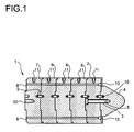
- FIG. 1 shows a nozzle head 1 according to the invention, in which at a inlet module 2, which is provided with a central bore 3, a nozzle tip 4 is fixed.
- the nozzle tip 4 with a screw 5, which is guided through the central bore 3, connected to the inlet module 2.
- the screw 5, which is guided through the central bore 3 it is also possible to fasten the nozzle tip 4 with a plurality of screws on the inlet module 2.
- the nozzle tip 4 z. B. also be welded to the inlet module 2 or the inlet module 2 is formed integrally with the nozzle tip 4.
- it would be z. B. also possible in the inlet module 2 to provide a bore with a thread and also form the nozzle tip with a thread, so that the nozzle tip 4 can be screwed directly onto the inlet module 2.
- a first intermediate module 6 is attached on the nozzle tip 4 opposite side of the entrance module 2. At this first intermediate module 6, further intermediate modules 6 connect. The conclusion forms an exit module 7, which is connected to the last intermediate module 6.
- the intermediate modules 6 and the outlet module 7 extending in the axial direction nozzle bores 8 are formed.
- the nozzle bores 8 are formed in the inlet module 2, the intermediate modules 6 and the exit module 7 at the same axial position, so that when connecting the modules 2, 6, 7 respectively continuous nozzle bores 8 arise.
- In order to facilitate the assembly of the modules 2, 6, 7 are each formed in these holes 9, in which centering pins 10 are added.
- connection of entry module 2, intermediate modules 6 and exit module 7 may, for. B. by means of clamping screws.
- In the embodiment shown here are provided on the outer circumference of the modules 2, 6, 7 blind holes 11, in each of which a thread is formed.
- To connect the modules 2, 6, 7 is on the blind holes 11 in FIG. 1 Not shown flat steel launched, which has holes at the corresponding positions at which the blind holes 11 are located. Through the holes in the flat steel screws are guided, which are screwed into the blind holes 11.
- a threaded bore 12 is formed in which z. B. can attach a cutting device.
- the cutting device With the help of the cutting device, the polymer melt, which emerges from the nozzle holes 8, cut into granules.
- the cutting device is preferably a rapidly rotating knife.
- the polymer melt is conveyed by means of a melt pump or an extruder in the direction of the inlet module 2.
- a melt pump or an extruder By the nozzle tip 4 ensures that no melt collects in the central region of the inlet module 2, but that the entire melt is transported to the nozzle holes 8. So that no dead zones arise between the individual nozzle bores, conical extensions 13 are formed at the inlet openings of the nozzle bores 8. By the conical extensions 13, the melt is passed into the nozzle holes 8.
- the polymer melt then flows through the nozzle bores 8 and emerges from the nozzle bores 8 at the exit module 7.
- the cutting of the polymer melt into granules takes place in a granulation chamber into which the nozzle head 1 opens.
- the granulation chamber is flowed through by a liquid.
- the granules cool, so that it is avoided that individual granules combine to form agglomerate.
- the liquid is under an increased pressure to prevent the polymer melt, which may still contain low boiler residues or blowing agent, from expanding.
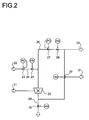
- FIG. 2 a process flow diagram of the method according to the invention is shown.
- a granulation chamber 20 is supplied with polymer melt 21.
- the supply of the polymer melt 21 takes place here, preferably via a nozzle head, as in FIG. 1 is shown.
- the granulation chamber 20 is flooded with a pressurized inert gas.
- the inert gas is fed via an inert gas 22 to the process.
- the pressure of the inert gas is adjusted via a pressure regulating valve 23.
- Via gas valve 24 an inert gas supply line 25 is connected to a circulation line 26.
- a second pressure control valve 27 is received.
- the second pressure control valve 27, a shut-off valve 28 is connected downstream.
- the shut-off valve 28 is closed and the gas valve 24 is opened. In this way, pressurized gas can flow into the circulation line 26.
- the granulation chamber 20 and the circulation line 26 are flooded with pressurized inert gas.
- From the circulation line 26 branches off a drain line 29, which is closed by a second shut-off valve 30.
- the second shut-off valve 30 is closed.
- liquid which is under the same pressure as the inert gas is introduced into the circulation line 26 via a liquid feed 31, which is connected via a T-valve 32 to the circulation line 26.
- the gas valve 24 is closed so that no more gas enters the process.
- the gas from the circulation line 26 and the granulation chamber 20 is displaced.
- the pressure in the circulation line 26 is kept constant.
- the shut-off valve 28 is opened, so that the liquid containing the granules produced in the granulation chamber 20 is removed via a liquid discharge 33 from the circulation line 26. Subsequently, the granules are separated from the liquid.
- Preferred inert gas which is used to start the process, is air or nitrogen.
- the liquid used for the current granulation process is preferably water.
Landscapes
- Engineering & Computer Science (AREA)
- Mechanical Engineering (AREA)
- Manufacturing & Machinery (AREA)
- Processing And Handling Of Plastics And Other Materials For Molding In General (AREA)
Description
- Die Erfindung betrifft ein Verfahren zur Granulierung von Polymerschmelzen in einer Granulierkammer, in der eine Schneidvorrichtung aufgenommen ist, bei einem Druck oberhalb des Umgebungsdrucks.
- Im laufenden Betrieb der Granulierung wird die Granulierkammer im Allgemeinen von einer unter erhöhtem Druck stehenden Flüssigkeit durchströmt. Die Flüssigkeit, die die Kammer durchströmt, ist im Allgemeinen Wasser. Daher wird die Granulierung auch als Unterwassergranulierung bezeichnet.
- Die Unterwassergranulierung kommt z. B. zum Einsatz, wenn Granulate aus Kunststoffen hergestellt werden, die durch die Herstellung noch Restmonomer, Wasser oder andere Leichtsieder enthalten können. Dies kann zu einem Aufschäumen des Kunststoffes bei der Granulierung bei Umgebungsdruck führen. Durch den erhöhten Druck in der Granulierkammer wird sichergestellt, dass der Kunststoff beim Granulieren nicht expandiert.
- Ein Verfahren zur Herstellung von expandierbaren Kunststoffgranulaten ist z. B. in
EP-A 0 305 862 beschrieben. Hierbei wird ein Polymergrundstoff oder eine Polymermischung einem Extruder zugegeben und im Extruder aufgeschmolzen. Am Extruder befindet sich ein Injektor zur Zugabe eines Treibmittels in die Schmelze. Die Zugabe des Treibmittels erfolgt dabei unter Druck. Die Schmelze mit dem darin gelösten Treibmittel wird in einer Granulierkammer, die von Wasser durchströmt wird, granuliert. Das Granulat wird mit dem Wasserstrom mitgerissen und einem Trockner zugeführt, in welchem das Granulat getrocknet wird. Als geeignete Polymerzusammensetzungen sind z.B. aromatische Alkenylpolymere oder Copolymere wie Polystryrol, Styrol-Maleinsäureanhydrid-Copolymer, Polycarbonat, Polyester, Polyetherimid, Polysulfon und Polyphenylether genannt. - Aus der Polyamidherstellung ist bekannt, dass sich Wasser, das bei der Polykondensation von Dicarbonsäure mit Diamin entsteht, im Polyamid löst. Dieses Wasser führt dazu, dass das Polyamid bei der Granulierung ohne Entgasung aufschäumt. Auch können große unerwünschte Blasen im Granulat entstehen. Die Entgasung erfolgt derzeit in einem Entgasungsextruder, der hohe Investions- und Wartungskosten erfordert, oder einem Abscheidebehälter, der schnell verkrustet und dann abgereinigt werden muss.
- Ein anderes Verfahren zur Herstellung von expandierbaren Kunststoffgranulaten ist in
DE 1 915 950 A1 beschrieben. - Aufgabe der Erfindung ist es, ein Verfahren bereitzustellen, bei dem die oben genannten Nachteile aus dem Stand der Technik vermieden werden.
- Gelöst wird die Aufgabe durch ein Verfahren zur Granulierung von Polymerschmelzen in einer Granulierkammer, in der eine Schneidvorrichtung aufgenommen ist, bei einem Druck oberhalb dem Umgebungsdruck, welches folgende Schritte umfasst:
- (a) Fluten der Granulierkammer mit einem gegenüber der Polymerschmelze inerten Gas, welches den Druck aufweist, bei dem die Granulierung durchgeführt wird,
- (b) Einpressen der Polymerschmelze in die Granulierkammer,
- (c) Verdrängen des Gases aus der Granulierkammer durch eine Flüssigkeit, sobald die Polymerschmelze beginnt, die Schneidevorrichtung zu durchfließen, wobei diese in Granulatkörner geschnitten wird.
- Durch das Fluten der Granulierkammer mit einem gegenüber der Polymerschmelze inerten Gas, welches den Druck aufweist, bei dem die Granulierung durchgeführt wird, wird vermieden, dass die Polymerschmelze beim Anfahren des Herstellungsprozesses in der Granulierkammer expandiert.
- In der Granulierkammer ist im Allgemein ein schnell rotierendes Messer aufgenommen, welches sich gegen eine Schneidplatte abstützt. Die Polymerschmelze wird durch einzelne Öffnungen in der Schneidplatte hindurch gepresst. Hierbei wird diese in Granulatkörner geschnitten.
- Das Einpressen der Polymerschmelze in die Granulierkammer erfolgt vorzugsweise kontinuierlich. Im Allgemeinen wird hierzu eine Schmelzpumpe mit Düsenkopf eingesetzt.
- Im Allgemeinen sind im Düsenkopf mehrere Bohrungen aufgenommen, durch welche die Polymerschmelze in die Granulierkammer eingepresst wird. In einer bevorzugten Ausführungsform weisen die Bohrungen ein L/D-Verhältnis von 50-90, bevorzugt von 60-85, besonders bevorzugt von 70-80 auf.
- Durch die größere Länge der Düsenbohrungen im Vergleich zu den Düsenbohrungen bei aus dem Stand der Technik bekannten Düsenköpfen wird ebenfalls das Aufschäumen der Polymerschmelze in der Granulierkammer reduziert. In einer besonders bevorzugten Ausführungsform ist der Düsenkopf aus einzelnen gleichartigen Modulen aufgebaut, die jeweils miteinander verbunden werden. Auf diese Weise lässt sich die Länge der Düsenbohrungen auf einfache Weise an die entsprechende Polymerschmelze anpassen, die mit dem Düsenkopf verarbeitet wird. So werden durch Hinzufügen von Modulen die Düsenbohrungen verlängert, während sie durch Entfernen von Modulen verkürzt werden können.
- Sobald die Polymerschmelze beginnt, die Schneidevorrichtung zu durchfließen, wobei diese in Granulatkörner geschnitten wird, wird das Gas aus der Granulierkammer durch eine Flüssigkeit verdrängt. Dabei steht die Flüssigkeit vorzugsweise nur unter geringfügigen höheren Druck als das Gas. Ein Fluten der Granulierkammer vor Beginn des Granulierprozesses ist nicht möglich, da in diesem Falle unter Druck stehende Flüssigkeit in den Düsenkopf eindringt und so die Polymerschmelze bereits im Düsenkopf aushärtet. Dies würde zu einer Beschädigung des Düsenkopfes und des Messers führen.
- Der Druck der Flüssigkeit in der Granulierkammer liegt im Allgemeinen im Bereich zwischen 1 und 50 bar, vorzugsweise im Bereich von 1,5 bis 30 bar und insbesondere im Bereich von 2 bis 10 bar. Die Temperatur der Flüssigkeit, mit der die Granulierkammer durchströmt wird, liegt vorzugsweise im Bereich von 5 bis 90°C, bevorzugt im Bereich von 10 bis 60°C. Die Maximaltemperatur der Flüssigkeit ist dabei abhängig von dem zu granulierenden Polymer.
- Das Fluten der Granulierkammer ist notwendig, um aus dem Granulat ausreichend Wärme abführen zu können, damit dieses schnell erstarrt. Solange das Granulat noch nicht erstarrt ist können die einzelnen Granulatkörner leicht zusammenschmelzen und zu größeren Körnern agglomerieren. Ein Vorteil von Flüssigkeiten gegenüber Gas für die Abkühlung ist, dass Flüssigkeiten im Allgemeinen eine höhere Wärmekapazität und höhere Wärmeleitfähigkeit aufweisen als Gase. Dies führt dazu, dass die Polymerschmelze an eine flüssige Umgebung schneller Wärme abgegeben kann als an eine gasförmige Umgebung und so schneller abkühlt.
- Nach dem Schneiden kühlen die Granulatkörner in der Flüssigkeit weiter ab. Um einen kontinuierlichen Betrieb zu gewährleisten, werden die Granulatkörner anschließend in einer bevorzugten Ausführungsform mit der Flüssigkeitsströmung aus der Granulierkammer ausgetragen.
- Das inerte Gas, mit welchem die Granulierkammer zu Beginn des Verfahrens geflutet wird, ist vorzugsweise Stickstoff, Luft oder ein Edelgas. Es ist jedoch jedes weitere, dem Fachmann bekannte Gas, welches gegenüber der Polymerschmelze inert ist, geeignet.
- Die Flüssigkeit, mit der das Gas aus der Granulierkammer verdrängt wird, ist vorzugsweise Wasser. Anstelle des Wassers ist jedoch auch jede weitere, dem Fachmann bekannte Flüssigkeit geeignet, die mit der Polymerschmelze nicht reagiert.
- In einer bevorzugten Ausführungsform werden die bei der Granulierung erzeugten Granulatkörner, die mit der Flüssigkeit aus der Granulierkammer ausgetragen wurden, anschließend aus der Flüssigkeit abgetrennt.
- Das erfindungsgemäße Verfahren wird vorzugsweise zur Granulierung von Polymeren eingesetzt, die noch geringe Mengen an Monomeren, Wasser oder anderen Leichtsiedern enthalten können und somit bei der Granulierung expandieren können. Damit das Polymer bei der Granulierung nicht aufschäumt, folgt die Granulierung unter Druck. Hierbei werden die enthaltenen leichtflüchtigen Bestandteile unter Druck im Polymer eingeschlossen. Ein Aufschäumen oder Entstehen von Blasen erfolgt nicht.
- Das Erfindungsgemäße Verfahren eignet sich insbesondere zur Herstellung von Granulaten aus Polymerschmelzen, die noch Leichtsieder enthalten. Bevorzugt wird das erfindungsgemäße Verfahren zur Herstellung von Polyamiden eingesetzt.
- Bevorzugte Polyamide werden durch Reaktionen von wässrigen Lösungen von Salzen aus α,ω -Alkandicarbonsäuren mit 6 bis 12 Kohlenstoffatomen und α,ω-Alkandiaminen mit 6 bis 12 Kohlenstoffatomen, insbesondere solchen mit gerader Kohlenstoffkette, gebildet. Geeignete Dicarbonsäuren sind beispielsweise Azelainsäure, Adipinsäure, Korksäure, Sebacinsäure oder Dekandicarbonsäure, Terephthalsäure oder Naphtalindicarbonsäure. Bevorzugte α, ω -Alkandicarbonsäuren haben 6 bis 10 Kohlenstoffatome.
- Geeignete Diamine sind beispielsweise Hexamethylendiamin, Octamethylendiamin oder Dekamethylendiamin, bis-(4-Aminocyclohexyl)-methan, bis-(4-Amino-3-methylcyclohexyl)-methan, bis-(4-Aminocyclohexyl)-propan-2,2. Bevorzugte α,ω-Alkandiamine haben 6 bis 10 Kohlenstoffatome.
- Zudem ist es möglich, Lactame, insbesondere Caprolactam, zur Herstellung von Mischpolyamiden mit zu verwenden.
- Weitere geeignete Polyamide sind solche, die aus einem Gemisch aus mindestens einem Lactam und Wasser sowie gegebenenfalls weiteren Monomereinheiten und/ oder üblichen Zusatz- und Füllstoffen unter Polyamidbildenden Bedingungen hergestellt werden. Die Herstellung solcher Polyamide ist z.B. aus
DE-A 43 21 683 bekannt. Als Lactam geeignet sind z.B. Caprolactam, Önanthlactam, Capryllactam und Lauryllactam sowie deren Mischungen, bevorzugt ist Caprolactam. - Als weitere Monomereinheiten können beispielsweise Dicarbonsäuren, wie Alkandicarbonsäuren mit 6 bis 12 Kohlenstoffatomen, insbesondere 6 bis 10 Kohlenstoffatomen, wie Adipinsäure, Pimelinsäure, Korksäure, Azelainsäure oder Sebacinsäure sowie Terephthalsäure oder Isophthalsäure, Diamine wie C4 bis C12-Alkyldiamine, insbesondere mit 4 bis 8 Kohlenstoffatomen wie Hexamethylendiamin, Tetramethylendiamin oder Octamethylendiamin, ferner m-Xylylendiamin, bis-(4-aminophenyl)-methan, bis-(4-Aminophenyl)-propan-2,2 oder bis-(4-aminocyclohexyl)-methan, sowie Mischungen von Dicarbonsäuren und Diaminen jeweils für sich in beliebigen Kombinationen, im Verhältnis jedoch vorteilhaft im äquivalenten Verhältnis wie Hexamethylendiammoniumadipat, Hexamethylendiammoniumterephthalat oder Tetramethylendiammoniumadipat, bevorzugt Hexamethylendiammoniumadipat und Hexamethylendiamoniumterephthalat, in Mengen im Bereich von 0 bis 60, vorzugsweise von 10 bis 50 Gew.-%, bezogen auf die Gesamtmenge an Monomeren, eingesetzt. Besondere technische Bedeutung haben Polycaprolactam und Polyamide, die aus Capolactam, Hexamethylendiamin sowie Adipinsäure, Isophthalsäure und/oder Terephthalsäure aufgebaut sind, erlangt.
- In einer Ausführungsform werden Caprolactam und Hexamethylendiamoniumadipat ("AH-Salz") eingesetzt, wobei das AH-Salz als wässrige Lösung verwendet wird. Üblicherweise liegt das Molverhältnis von Caprolactam zu AH-Salz im Bereich von 0,05 zu 99,95 bis 20 zu 80, bevorzugt von 5 zu 95 bis 15 zu 85.
- Als übliche Zusatz- und Füllstoffe können Pigmente wie Titandioxid, Siliciumdioxid oder Talk, Kettenregler wie aliphatische und aromatische Carbon- und Dicarbonsäuren wie Propionsäure oder Terephthalsäure, Stabilisatoren wie Kupfer(1)halogenide und Alkalimetallhalogenide, Nukleierungsmittel wie Magnesiumsilikat oder Bornitrid, Katalysatoren wie phosphorige Säure sowie Antioxidantien in Mengen im Bereich von 0 bis 5, bevorzugt von 0,05 bis 1 Gew.-%, bezogen auf die Gesamtmenge an Monomeren eingesetzt werden. Die Additive werden in der Regel von dem Granulieren und vor, während oder nach, bevorzugt nach der Polymerisation zugesetzt.
- Erfindungsgemäß geeignete Polyamide weisen im Allgemeinen eine Viskositätszahl von 30 bis 120, vorzugsweise 50 bis 90 ml/g auf, bestimmt in einer 0,5 Gew.-% -igen Lösung in 96 Gew.-%- iger Schwefelsäure bei 25 °C gemäß ISO 307.
- Polyamide, die durch das erfindungsgemäße Verfahren granuliert werden können, sind z.B. (in Klammern sind die Monomere angegeben):
- PA 46 (Tetramethylendiamin, Adipinsäure)
- PA 66 (Hexamethylendiamin, Adipinsäure)
- PA 69 (Hexamethylendiamin, Azelainsäure)
- PA 610 (Hexamethylendiamin, Sebacinsäure)
- PA 612 (Hexamethylendiamin, Decandicarbonsäure)
- PA 613 (Hexamethylendiamin, Undecandicarbonsäure)
- PA 1212 (1,12-Dodecandiamin, Decandicarbonsäure)
- PA 1313 (1,13 Diaminotridecan, Undecandicarbonsäure)
- PA MXD6 (m-Xylylendiamin, Adipinsäure)
- PA TMDT (Trimethylhexamethylendiamin, Terephthalsäure)
- Bevorzugte Polyamide sind Polyhexamethylenadipinsäureamid (PA 66) und Polyhexamethylensebacinsäureamid (PA 610) sowie Copolyamide 6/66, insbesondere mit einem Anteil von 5 bis 50 Gew.-% an Caprolactam-Einheiten. PA 66 und Copolyamide 6/66 sind besonders bevorzugt.
- Weiterhin sind auch teilaromatische Copolyamide wie PA 6/6T und PA 66/6T, deren Triamingehalt weniger 0,5, vorzugsweise weniger als 0,3 Gew.-% beträgt, geeignet. Die Herstellung der teilaromatischen Copolyamide mit niedrigem Triamingehalt kann z.B. nach den in
EP-A 129 195 EP-A 129 196 - Einzelheiten zur Herstellung der einzelnen Polyamide findet der Fachmann z.B. in Ullmanns Enzyklopädie der technischen Chemie, 4. Auflage, Band 19, Seiten 39 bis 54, Verlag Chemie, Weinheim 1980, sowie Ullmanns Encyclopedia of Industrial Chemistry, Vol. A 21, Seiten 179 bis 206, VCH Verlag, Weinheim 1992, sowie Stoeckhert, Kunststofflexikon, 8. Auflage, Seiten 425 bis 428, Hansa Verlag München 1992 (Stichwort "Polyamide" und folgende).
- Treibmittelhaltige Polymere im Sinne der vorliegenden Erfindung sind z. B. treibmittelhaltige Styrol(co)polymere, treibmittelhaltiges Polycarbonat und treibmittelhaltiges Polyamid, besonders bevorzugt sind treibmittelhaltige Styrol(co)polymere sowie Polymere, die noch ausgasbare Komponenten enthalten können, z. B. Lösungsmittel oder Wasser aus dem Herstellungsprozess.
- Bevorzugte Styrol(co)polymere sind glasklares Polystyrol (GPPS), schlagzäh modifiziertes Polystyrol (HIPS), anionisch polymerisiertes Polystyrol oder anionisch polymerisiertes schlagzäh modifiziertes Polystyrol (A-IPS), Styrol-α-Methylstyrol-Copolymere, Acrylnitril-Butadien-Styrol-Copolymere (ABS), Styrol-Acrylnitril (SAN), Acrylnitril-Styrol-Acrylester (ASA), Methacrylat-Butadien-Styrol (MBS), Methylmethacrylat-Acrylnitril-Butadien-Styrol (MABS)-Copolymerisate oder Mischungen daraus. Den genannten Styrol(co)polymeren kann zusätzlich Polyphenylenether (PPE) beigemischt sein.
- Die genannten Styrol(co)polymere können zur Verbesserung der mechanischen Eigenschaften oder der Temperaturbeständigkeit gegebenenfalls unter Verwendung von Verträglichkeitsvermittlern mit thermoplastischen Polymeren, wie Polyamiden (PA), Polyolefinen, wie Polypropylen (PP) oder Polyethylen (PE), Polyacrylaten, wie Polymethylmethacrylat (PMMA), Polycarbonat (PC), Polyestern, wie Polyethylenterephthalat (PET) oder Polybutylenterephthalat (PBT), Polyethersulfonen (PES), Polyetherketonen oder Polyethersulfiden (PES) oder Mischungen davon, in der Regel in Anteilen von insgesamt bis maximal 30 Gew.-%, bevorzugt im Bereich von 1 bis 10 Gew.-%, bezogen auf die Polymerschmelze, abgemischt werden. Des Weiteren sind Mischungen in den genannten Mengenbereichen auch mit z. B. hydrophob modifizierten oder funktionalisierten Polymeren oder Oligomeren, Kautschuken, wie Polyacrylaten oder Polydienen, z. B. Styrol-Butadien-Blockcopolymeren oder biologisch abbaubaren aliphatischen oder aliphatisch/aromatischen Copolyestern, möglich.
- Der Styrol(co)polymerschmelze können auch Polymer-Recyclate der genannten thermoplastischen Polymere, insbesondere Styrol(co)polymere und treibmittelhaltige Styrol(co)polymere (EPS), in Mengen zugemischt werden, die deren Eigenschaften nicht wesentlich verschlechtern, in der Regel in Mengen von maximal 30 Gew.-%, insbesondere in Mengen von 1 bis 10 Gew.-%.
- Die treibmittelhaltige Styrol(co)polymerschmelze enthält in der Regel ein oder mehrere Treibmittel in homogener Verteilung in einem Anteil von insgesamt 2 bis 10 Gew.-%, bezogen auf die treibmittelhaltige Styrol(co)polymerschmelze. Als Treibmittel eignen sich die üblicherweise in EPS eingesetzten physikalischen Treibmittel, wie aliphatische Kohlenwasserstoffe mit 2 bis 7 Kohlenstoffatomen, Alkohole, Ketone, Ether oder halogenierte Kohlenwasserstoffe. Bevorzugt wird Iso-Butan, n-Butan, Iso-Pentan, n-Pentan eingesetzt.
- Des Weiteren können der Styrol(co)polymerschmelze Additive, Keimbildner, Weichmacher, Wirkstoffe, z. B. Fungizide, Pestizide, Herbizide, lösliche und unlösliche anorganische und/oder organische Farbstoffe und Pigmente, z. B. IR-Absorber, wie Ruß, Graphit oder Aluminiumpulver, sowie Füllstoffe, z. B. Kreide, Talkum, gemeinsam oder räumlich getrennt zugegeben werden. In der Regel werden die Additive in Mengen im Bereich von 0,01 bis 30, bevorzugt im Bereich von 1 bis 10 Gew.-% zugesetzt. Zur homogenen und mikrodispersen Verteilung der Additive in dem Styrol(co)polymer kann es insbesondere bei polaren Additiven zweckmäßig sein, ein Dispergierhilfsmittel, z. B. Organosilane oder Maleinsäureanhydrid-gepfropfte Styrolpolymere, einzusetzen. Bevorzugte Weichmacher sind Mineralöle, oligomere Styrolpolymere, Phthalate in Mengen von 0,05 bis 10 Gew.-%, bezogen auf das Styrol(co)polymerisat.
- Die höhermolekularen Styrol(co)polymerisate erlauben, dass die treibmittelhaltige Styrol(co)polymerschmelze mit einer Temperatur im Bereich von 140 bis 300 °C, bevorzugt im Bereich von 160 bis 240 °C durch die Düsenplatte gefördert werden kann. Eine Abkühlung bis in den Bereich der Glasübergangstemperatur ist nicht notwendig.
- Im folgenden wird die Erfindung anhand einer Zeichnung näher beschrieben. Darin zeigt:
-
Figur 1 einen erfindungsgemäß ausgebildeten Düsenkopf, -
Figur 2 ein Verfahrensfließbild des erfindungsgemäßen Verfahrens. -
Figur 1 zeigt einen erfindungsgemäß ausgebildeten Düsenkopf 1, bei dem an einem Eintrittsmodul 2, welches mit einer zentralen Bohrung 3 versehen ist, eine Düsenspitze 4 befestigt ist. Hierzu ist die Düsenspitze 4 mit einer Schraube 5, welche durch die zentral Bohrung 3 geführt ist, mit dem Eintrittsmodul 2 verbunden. An Stelle der Schraube 5, welche durch die zentrale Bohrung 3 geführt ist, ist es jedoch auch möglich die Düsenspitze 4 mit mehreren Schrauben am Eintrittsmodul 2 zu befestigen. Auch ist jede weitere, dem Fachmann bekannte Befestigungsart, möglich. So kann die Düsenspitze 4 z. B. auch mit dem Eintrittsmodul 2 verschweißt sein oder das Eintrittsmodul 2 ist einstückig mit der Düsenspitze 4 ausgebildet. Weiterhin wäre es z. B. auch möglich im Eintrittsmodul 2 eine Bohrung mit einem Gewinde vorzusehen und die Düsenspitze ebenfalls mit einem Gewinde auszubilden, sodass die Düsenspitze 4 direkt auf das Eintrittsmodul 2 aufgeschraubt werden kann. - Auf der der Düsenspitze 4 gegenüberliegenden Seite des Eintrittsmoduls 2 ist ein erstes Zwischenmodul 6 befestigt. An dieses erste Zwischenmodul 6 schließen sich weitere Zwischenmodule 6 an. Den Abschluss bildet ein Austrittsmodul 7, welches mit dem letzten Zwischenmodul 6 verbunden ist.
- Im Eintrittsmodul 2, den Zwischenmodulen 6 und dem Austrittsmodul 7 sind in axialer Richtung verlaufende Düsenbohrungen 8 ausgebildet. Durch die Anzahl der Düsenbohrungen 8 wird die Menge der an Polymerschmelze, welche durch den Düsenkopf 1 strömt und granuliert wird, bestimmt. Die Düsenbohrungen 8 sind dabei im Eintrittsmodul 2, den Zwischenmodulen 6 und dem Austrittsmodul 7 an der axial gleichen Position ausgebildet, so dass beim Verbinden der Module 2, 6, 7 jeweils durchgehende Düsenbohrungen 8 entstehen. Um die Montage der Module 2, 6, 7 zu erleichtern sind in diesen jeweils Bohrungen 9 ausgebildet, in denen Zentrierstifte 10 aufgenommen sind.
- Die Verbindung von Eintrittsmodul 2, Zwischenmodulen 6 und Austrittsmodul 7 kann z. B. mit Hilfe von Spannschrauben erfolgen. In der hier dargestellten Ausführungsform sind am Außenumfang der Module 2, 6, 7 Sacklöcher 11 vorgesehen, in denen jeweils ein Gewinde ausgebildet ist. Zur Verbindung der Module 2, 6, 7 wird auf die Sacklöcher 11 ein in
Figur 1 nicht dargestellter Flachstahl aufgelegt, der an den entsprechenden Positionen, an denen sich die Sacklöcher 11 befinden, Bohrungen aufweist. Durch die Bohrungen im Flachstahl werden Schrauben geführt, die in den Sacklöchern 11 verschraubt werden. - Im Austrittsmodul 7 ist eine Gewindebohrung 12 ausgebildet, in der sich z. B. eine Schneidevorrichtung befestigen lässt. Mit Hilfe der Schneidvorrichtung wird die Polymerschmelze, die aus den Düsenbohrungen 8 austritt, in Granulat geschnitten. Hierbei ist die Schneidevorrichtung vorzugsweise ein schnell rotierendes Messer.
- Zur Herstellung von Polymergranulat wird die Polymerschmelze mittels einer Schmelzepumpe oder eines Extruders in Richtung des Eintrittsmoduls 2 gefördert. Durch die Düsenspitze 4 wird gewährleistet, dass sich keine Schmelze im zentralen Bereich des Eintrittsmoduls 2 sammelt, sondern das die gesamte Schmelze zu den Düsenbohrungen 8 transportiert wird. Damit auch zwischen den einzelnen Düsenbohrungen keine Totzonen entstehen, sind an den Eintrittsöffnungen der Düsenbohrungen 8 konische Erweiterungen 13 ausgebildet. Durch die konischen Erweiterungen 13 wird die Schmelze in die Düsenbohrungen 8 geleitet. Die Polymerschmelze strömt dann durch die Düsenbohrungen 8 und tritt am Austrittmodul 7 aus den Düsenbohrungen 8 aus. Hier werden die einzelnen Schmelzefäden, die aus den Düsenbohrungen 8 austreten, in Granulat geschnitten. Erfindungsgemäß erfolgt das Schneiden der Polymerschmelze in Granulat in einer Granulierkammer, in welche der Düsenkopf 1 mündet. Die Granulierkammer ist dabei von einer Flüssigkeit durchströmt. In der Flüssigkeit kühlt das Granulat ab, sodass vermieden wird, dass sich einzelne Granulatkörner zu Agglomerat miteinander verbinden. Gleichzeitig ist die Flüssigkeit unter einem erhöhten Druck, damit vermieden wird, dass sich die Polymerschmelze, welche noch Leichtsiederreste oder Treibmittel enthalten kann, expandiert.
- In
Figur 2 ist ein Verfahrensfließbild des erfindungsgemäßen Verfahren dargestellt. - Bei dem erfindungsgemäßen Verfahren wird einer Granulierkammer 20 Polymerschmelze 21 zugeführt. Die Zufuhr der Polymerschmelze 21 erfolgt dabei, vorzugsweise über einen Düsenkopf, wie er in
Figur 1 dargestellt ist. Zum Anfahren des Granulierprozesses ist die Granulierkammer 20 mit einem unter Druck stehenden Inertgas geflutet. Das Inertgas wird über eine Inertgaszufuhr 22 dem Prozess zugeführt. Der Druck des Inertgases wird über ein Druckregelventil 23 eingestellt. Über ein Gasventil 24 ist eine Inertgaszufuhrleitung 25 mit einer Kreislaufleitung 26 verbunden. In der Kreislaufleitung 26 ist ein zweites Druckregelventil 27 aufgenommen. Über das Druckregeventil 27 wird der Druck in der Kreislaufleitung 26 eingestellt. Dem zweiten Druckregelventil 27 ist ein Absperrventil 28 nachgeschaltet. Zum Anfahren des Granulierprozesses ist das Absperrventil 28 verschlossen und das Gasventil 24 geöffnet. Auf diese Weise kann unter Druck stehendes Gas in die Kreislaufleitung 26 einströmen. Die Granulierkammer 20 und die Kreislaufleitung 26 werden so mit unter Druck stehenden Inertgas geflutet. Aus der Kreislaufleitung 26 zweigt eine Entleerungsleitung 29 ab, welche mit einem zweiten Absperrventil 30 verschließbar ist. Während des Granulierbetriebes ist das zweite Absperrventil 30 verschlossen. Sobald der Granulierprozess gestartet ist wird über eine Flüssigkeitszufuhr 31, welche über ein T-Ventil 32 mit der Kreislaufleitung 26 verbunden ist, Flüssigkeit, die unter dem gleichen Druck steht wie das Inertgas, in die Kreislaufleitung 26 eingeleitet. Gleichzeitig wird das Gasventil 24 geschlossen, damit kein weiteres Gas mehr in den Prozess gelangt. Durch die unter Druck stehende Flüssigkeit wird das Gas aus der Kreislaufleitung 26 und der Granulierkammer 20 verdrängt. Durch das zweite Druckregelventil 27 wird der Druck in der Kreislaufleitung 26 konstant gehalten. Das Absperrventil 28 wird geöffnet, so dass die Flüssigkeit, die das in der Granulierkammer 20 hergestellte Granulat enthält, über einen Flüssigkeitsaustrag 33 aus der Kreislaufleitung 26 entfernt wird. Anschließend wird aus der Flüssigkeit das Granulat abgetrennt. - Bevorzugtes Inertgas, welches zum Anfahren des Prozesses eingesetzt wird, ist Luft oder Stickstoff. Als Flüssigkeit für den laufenden Granulierprozess wird vorzugsweise Wasser eingesetzt.
-
- 1
- Düsenkopf
- 2
- Eintrittsmodul
- 3
- zentrale Bohrung
- 4
- Düsenspitze
- 5
- Schraube
- 6
- Zwischenmodul
- 7
- Austrittsmodul
- 8
- Düsenbohrung
- 9
- Bohrung
- 10
- Zentrierstift
- 11
- Sackloch
- 12
- Gewindebohrung
- 13
- konische Erweiterung
- 20
- Granulierkammer
- 21
- Polymerschmelze
- 22
- Inertgaszufuhr
- 23
- Druckregelventil
- 24
- Gasventil
- 25
- Inertgaszufuhrleitung
- 26
- Kreislaufleitung
- 27
- zweites Druckregelventil
- 28
- Absperrventil
- 29
- Entleerungsleitung
- 30
- zweites Absperrventil
- 31
- Flüssigkeitszufuhr
- 32
- T-Ventil
- 33
- Flüssigkeitsaustrag
Claims (7)
- Verfahren zur Granulierung von Polymerschmelzen in einer Granulierkammer, in der eine Schneidevorrichtung aufgenommen ist, bei einem Druck oberhalb dem Umgebungsdruck, welches folgende Schritte umfasst:(a) Fluten der Granulierkammer mit einem gegenüber der Polymerschmelze inerten Gas, welches den Druck aufweist, bei dem die Granulierung durchgeführt wird,(b) Einpressen der Polymerschmelze in die Granulierkammer,(c) Verdrängen des Gases aus der Granulierkammer durch eine Flüssigkeit, sobald die Polymerschmelze beginnt, die Schneidevorrichtung zu durchfließen, wobei diese in Granulatkörner geschnitten wird.
- Verfahren nach Anspruch 1, dadurch gekennzeichnet, dass das Gas Stickstoff oder Luft ist.
- Verfahren nach Anspruch 1 oder 2, dadurch gekennzeichnet, dass nach dem Verdrängen des Gases durch die Flüssigkeit weiterhin Polymerschmelze in die Granulierkammer eingepresst wird, die Polymerschmelze in der Schneidevorrichtung zu Granulatkörnern geschnitten wird und die bei der Granulierung erzeugten Granulatkörner mit der Flüssigkeit aus der Granulierkammer ausgetragen und anschließend aus der Flüssigkeit abgetrennt werden.
- Verfahren nach einem der Ansprüche 1 bis 3, dadurch gekennzeichnet, dass der Druck in der Granulierkammer im Bereich von 2 bis 15 bar liegt.
- Vorrichtung zur Durchführung des Verfahrens nach einem der Ansprüche 1 bis 4, eine Granulierkammer (20) umfassend, die mit einem Flüssigkeitskreislauf (26) verbunden ist, wobei die Polymerschmelze über einen Düsenkopf (1) in die Granulierkammer (20) eingespritzt wird, wobei in dem Düsenkopf (1) Düsenbohrungen (8) ausgebildet sind, dadurch gekennzeichnet, dass das L/D-Verhältnis der Düsenbohrungen im Bereich von 50 bis 90 liegt.
- Vorrichtung nach Anspruch 5, dadurch gekennzeichnet dass der Düsenkopf (1) aus einzelnen Modulen (2,6,7) zusammengesetzt ist.
- Vorrichtung nach Anspruch 6, dadurch gekennzeichnet, dass der Düsenkopf (1) zur Einstellung des L/D-Verhältnisses mehrere gleichartige Module (6) umfasst, die in Reihe montiert werden, bis die gewünschte Länge der Düsenbohrungen (8) erreicht ist.
Priority Applications (3)
| Application Number | Priority Date | Filing Date | Title |
|---|---|---|---|
| EP12156066.8A EP2476532A3 (de) | 2006-03-22 | 2007-03-21 | Vorrichtung zur Granulierung von leichtsiederhaltigen Polymerschmelzen |
| PL07727158T PL1998944T3 (pl) | 2006-03-22 | 2007-03-21 | Sposób granulacji stopów polimerowych zawierających związki niskowrzące |
| EP07727158.3A EP1998944B1 (de) | 2006-03-22 | 2007-03-21 | Verfahren zur granulierung von leichtsiederhaltigen polymerschmelzen |
Applications Claiming Priority (3)
| Application Number | Priority Date | Filing Date | Title |
|---|---|---|---|
| EP06111527 | 2006-03-22 | ||
| PCT/EP2007/052681 WO2007107584A2 (de) | 2006-03-22 | 2007-03-21 | Verfahren zur granulierung von leichtsiederhaltigen polymerschmelzen |
| EP07727158.3A EP1998944B1 (de) | 2006-03-22 | 2007-03-21 | Verfahren zur granulierung von leichtsiederhaltigen polymerschmelzen |
Related Child Applications (2)
| Application Number | Title | Priority Date | Filing Date |
|---|---|---|---|
| EP12156066.8A Division-Into EP2476532A3 (de) | 2006-03-22 | 2007-03-21 | Vorrichtung zur Granulierung von leichtsiederhaltigen Polymerschmelzen |
| EP12156066.8A Division EP2476532A3 (de) | 2006-03-22 | 2007-03-21 | Vorrichtung zur Granulierung von leichtsiederhaltigen Polymerschmelzen |
Publications (2)
| Publication Number | Publication Date |
|---|---|
| EP1998944A2 EP1998944A2 (de) | 2008-12-10 |
| EP1998944B1 true EP1998944B1 (de) | 2015-10-28 |
Family
ID=38180739
Family Applications (2)
| Application Number | Title | Priority Date | Filing Date |
|---|---|---|---|
| EP12156066.8A Withdrawn EP2476532A3 (de) | 2006-03-22 | 2007-03-21 | Vorrichtung zur Granulierung von leichtsiederhaltigen Polymerschmelzen |
| EP07727158.3A Not-in-force EP1998944B1 (de) | 2006-03-22 | 2007-03-21 | Verfahren zur granulierung von leichtsiederhaltigen polymerschmelzen |
Family Applications Before (1)
| Application Number | Title | Priority Date | Filing Date |
|---|---|---|---|
| EP12156066.8A Withdrawn EP2476532A3 (de) | 2006-03-22 | 2007-03-21 | Vorrichtung zur Granulierung von leichtsiederhaltigen Polymerschmelzen |
Country Status (12)
| Country | Link |
|---|---|
| US (1) | US7897077B2 (de) |
| EP (2) | EP2476532A3 (de) |
| JP (1) | JP5215989B2 (de) |
| KR (1) | KR101375970B1 (de) |
| CN (1) | CN101405115B (de) |
| BR (1) | BRPI0709649A2 (de) |
| CA (1) | CA2646703A1 (de) |
| ES (1) | ES2556251T3 (de) |
| IL (1) | IL193983A (de) |
| MX (1) | MX2008011805A (de) |
| PL (1) | PL1998944T3 (de) |
| WO (1) | WO2007107584A2 (de) |
Families Citing this family (8)
| Publication number | Priority date | Publication date | Assignee | Title |
|---|---|---|---|---|
| ITMI20071005A1 (it) | 2007-05-18 | 2008-11-19 | Polimeri Europa Spa | Procedimento per la preparazione di granuli a base di polimeri termoplastici espandibili e relativo prodotto |
| DE202010003348U1 (de) * | 2010-03-09 | 2010-07-22 | Automatik Plastics Machinery Gmbh | Vorrichtung zum Herstellen von Granulatkörnern |
| DE102011018403A1 (de) * | 2011-04-21 | 2012-10-25 | Automatik Plastics Machinery Gmbh | Verfahren zur Herstellung von pharmazeutischen Erzeugnissen aus einem Schmelzematerial |
| WO2016017518A1 (ja) | 2014-07-30 | 2016-02-04 | 三菱瓦斯化学株式会社 | ポリアミドペレット、ポリアミドペレットの製造方法、及びポリアミド成形体の製造方法 |
| US11292156B2 (en) * | 2014-12-08 | 2022-04-05 | Borealis Ag | Process for producing pellets of copolymers of propylene |
| DE102015210966A1 (de) * | 2015-06-15 | 2016-12-15 | Maag Automatik Gmbh | Kunststoffgranulat und Verfahren zur Herstellung von Kunststoffgranulat |
| US10500777B2 (en) | 2016-07-01 | 2019-12-10 | Gala Industries, Inc. | Method and apparatus for forming an expandable foam pellet having a hard outer shell by underwater pelletizing, and expandable foam pellets formed thereby |
| CN111187409B (zh) * | 2020-01-09 | 2022-07-12 | 万华化学集团股份有限公司 | 半芳香聚酰胺的降压聚合方法及其装置 |
Citations (8)
| Publication number | Priority date | Publication date | Assignee | Title |
|---|---|---|---|---|
| DE1915950A1 (de) | 1968-05-27 | 1969-12-04 | Basf Ag | Verfahren zum Granulieren treibmittelhaltiger thermoplastischer Kunststoffe |
| DE2814113A1 (de) | 1978-04-01 | 1979-10-04 | Werner & Pfleiderer | Vorrichtung zum granulieren von kunststoffstraengen |
| US4327050A (en) | 1980-09-22 | 1982-04-27 | Phillips Petroleum Company | Extrusion and pelleting apparatus and method |
| DE3702841A1 (de) | 1986-01-31 | 1987-08-20 | Gala Inc | Unterwassergranulator |
| US4759889A (en) | 1984-10-19 | 1988-07-26 | Phillips Petroleum Company | Pelletizer control |
| US5143673A (en) | 1989-12-15 | 1992-09-01 | Werner & Pfleiderer Gmbh | Process and apparatus for underwater granulation of molten thermoplastic material particularly during start-up periods |
| WO2001019580A1 (de) | 1999-09-15 | 2001-03-22 | Cognis Deutschland Gmbh & Co. Kg | Verfahren zum konfektionieren von bei raumtemperatur festen polyamidharzen |
| US20050140044A1 (en) | 2003-07-30 | 2005-06-30 | Jackson Richard A. | Polymer pelletization process and apparatus |
Family Cites Families (18)
| Publication number | Priority date | Publication date | Assignee | Title |
|---|---|---|---|---|
| DE1915950U (de) * | 1965-02-19 | 1965-05-20 | Kurt Katzenmaier | Abscherverbindung fuer glasfaserverstaerkte polyester-leitpfosten. |
| US3874835A (en) | 1971-04-02 | 1975-04-01 | Welding Engineers | Face-cutting apparatus for forming pellets |
| GB1382701A (en) * | 1971-04-02 | 1975-02-05 | Welding Engineers | Face cutting apparatus for forming pellets |
| DE2455757A1 (de) | 1974-11-26 | 1976-06-10 | Basf Ag | Verfahren und vorrichtung zum granulieren thermoplastischer massen |
| DE3321579A1 (de) | 1983-06-15 | 1984-12-20 | Basf Ag, 6700 Ludwigshafen | Verfahren zur kontinuierlichen herstellung von polyamiden |
| DE3321581A1 (de) | 1983-06-15 | 1984-12-20 | Basf Ag, 6700 Ludwigshafen | Verfahren zur kontinuierlichen herstellung von polyamiden |
| DE3708291A1 (de) * | 1987-03-14 | 1988-09-22 | Basf Ag | Verfahren zur herstellung von polyolefinschaumstoffen |
| EP0305862A1 (de) | 1987-09-04 | 1989-03-08 | General Electric Company | Einstufenverfahren für die Herstellung von expandierbaren Schaumperlen |
| US5234963A (en) * | 1992-05-13 | 1993-08-10 | Gaia Research | Production of encapsulated chemical foaming concentrates |
| DE4321683A1 (de) | 1993-06-30 | 1995-01-12 | Basf Ag | Verfahren zum kontinuierlichen Herstellen von niedermolekularen Polyamiden |
| JPH11179724A (ja) * | 1997-12-24 | 1999-07-06 | Kobe Steel Ltd | 水中カット造粒装置及び水中カット造粒装置の起動方法 |
| EP1132420B1 (de) * | 2000-01-25 | 2006-04-12 | Basf Aktiengesellschaft | Verfahren zur Herstellung von Partikelfoermigen, Expandierbaren Propylenpolymerisaten |
| CA2441515A1 (en) * | 2001-03-29 | 2002-10-10 | Dong Hee Kim | Apparatus for manufacturing foamed thermoplastic resin pellets and method thereof |
| DE10209149A1 (de) | 2002-03-01 | 2003-09-18 | Bayer Ag | Verfahren zur Herstellung von Kunststoffgranulaten |
| MXPA05010953A (es) * | 2003-04-11 | 2005-12-15 | Polymer Group Inc | Metodo para formar materiales polimericos utilizando unidades de dados modulares. |
| JP4173850B2 (ja) * | 2004-10-13 | 2008-10-29 | 株式会社日本製鋼所 | Uwc装置、uwc装置におけるpcw循環システム、及びuwc装置を用いたペレット成形加工方法 |
| CH711770B1 (de) * | 2006-03-13 | 2017-05-15 | Uhde Inventa-Fischer Ag | Verfahren zur Herstellung eines nicht klebenden Granulats aus einem Polyestermaterial und zur Weiterverarbeitung eines so hergestellten Granulats. |
| TWM325201U (en) * | 2007-05-29 | 2008-01-11 | Pitac Internat Machinery Co Lt | Improved structure of underwater granulating platform |
-
2007
- 2007-03-21 ES ES07727158.3T patent/ES2556251T3/es active Active
- 2007-03-21 MX MX2008011805A patent/MX2008011805A/es unknown
- 2007-03-21 CN CN2007800100671A patent/CN101405115B/zh not_active Expired - Fee Related
- 2007-03-21 WO PCT/EP2007/052681 patent/WO2007107584A2/de active Application Filing
- 2007-03-21 JP JP2009500862A patent/JP5215989B2/ja not_active Expired - Fee Related
- 2007-03-21 EP EP12156066.8A patent/EP2476532A3/de not_active Withdrawn
- 2007-03-21 US US12/293,939 patent/US7897077B2/en not_active Expired - Fee Related
- 2007-03-21 PL PL07727158T patent/PL1998944T3/pl unknown
- 2007-03-21 EP EP07727158.3A patent/EP1998944B1/de not_active Not-in-force
- 2007-03-21 CA CA002646703A patent/CA2646703A1/en not_active Abandoned
- 2007-03-21 BR BRPI0709649-6A patent/BRPI0709649A2/pt not_active Application Discontinuation
- 2007-03-21 KR KR1020087022905A patent/KR101375970B1/ko not_active IP Right Cessation
-
2008
- 2008-09-09 IL IL193983A patent/IL193983A/en not_active IP Right Cessation
Patent Citations (8)
| Publication number | Priority date | Publication date | Assignee | Title |
|---|---|---|---|---|
| DE1915950A1 (de) | 1968-05-27 | 1969-12-04 | Basf Ag | Verfahren zum Granulieren treibmittelhaltiger thermoplastischer Kunststoffe |
| DE2814113A1 (de) | 1978-04-01 | 1979-10-04 | Werner & Pfleiderer | Vorrichtung zum granulieren von kunststoffstraengen |
| US4327050A (en) | 1980-09-22 | 1982-04-27 | Phillips Petroleum Company | Extrusion and pelleting apparatus and method |
| US4759889A (en) | 1984-10-19 | 1988-07-26 | Phillips Petroleum Company | Pelletizer control |
| DE3702841A1 (de) | 1986-01-31 | 1987-08-20 | Gala Inc | Unterwassergranulator |
| US5143673A (en) | 1989-12-15 | 1992-09-01 | Werner & Pfleiderer Gmbh | Process and apparatus for underwater granulation of molten thermoplastic material particularly during start-up periods |
| WO2001019580A1 (de) | 1999-09-15 | 2001-03-22 | Cognis Deutschland Gmbh & Co. Kg | Verfahren zum konfektionieren von bei raumtemperatur festen polyamidharzen |
| US20050140044A1 (en) | 2003-07-30 | 2005-06-30 | Jackson Richard A. | Polymer pelletization process and apparatus |
Also Published As
| Publication number | Publication date |
|---|---|
| JP5215989B2 (ja) | 2013-06-19 |
| US20090051061A1 (en) | 2009-02-26 |
| CN101405115B (zh) | 2012-04-04 |
| US7897077B2 (en) | 2011-03-01 |
| IL193983A (en) | 2013-10-31 |
| ES2556251T3 (es) | 2016-01-14 |
| MX2008011805A (es) | 2008-09-29 |
| KR101375970B1 (ko) | 2014-03-18 |
| CN101405115A (zh) | 2009-04-08 |
| CA2646703A1 (en) | 2007-09-27 |
| JP2009530142A (ja) | 2009-08-27 |
| EP2476532A2 (de) | 2012-07-18 |
| KR20080104325A (ko) | 2008-12-02 |
| WO2007107584A3 (de) | 2008-01-31 |
| EP1998944A2 (de) | 2008-12-10 |
| EP2476532A3 (de) | 2017-09-27 |
| WO2007107584A2 (de) | 2007-09-27 |
| PL1998944T3 (pl) | 2016-04-29 |
| BRPI0709649A2 (pt) | 2011-07-19 |
Similar Documents
| Publication | Publication Date | Title |
|---|---|---|
| EP1998944B1 (de) | Verfahren zur granulierung von leichtsiederhaltigen polymerschmelzen | |
| EP1998948B2 (de) | Verfahren und vorrichtung zur granulierung von treibmittelhaltigen polymerschmelzen | |
| EP1517947B1 (de) | Verfahren zur herstellung von expandierbarem polystyrol | |
| EP2162269B1 (de) | Expandierbare Polymergranulate aus Acrylnitrilcopolymeren | |
| EP0734825B1 (de) | Verfahren zur Herstellung von Thermoplasten | |
| EP0735078B1 (de) | Verfahren zur Herstellung von Thermoplasten | |
| EP0735077B1 (de) | Verfahren zur Herstellung von Thermoplasten | |
| DE10358801A1 (de) | Partikelschaumformteile aus expandierbaren Styrolpolymeren und Mischungen mit thermoplastischen Polymeren | |
| DE2239900A1 (de) | Verfahren und vorrichtung zur herstellung geschaeumter thermoplastischer kunststoffe | |
| EP1719600B1 (de) | Verfahren zur Erzeugung einer Schaumkunststoff-Folie | |
| WO2006007996A1 (de) | Synergistische flammschutzmischungen für polystyrolschaumstoffe | |
| EP0734826B1 (de) | Verfahren zur Herstellung von Thermoplasten | |
| EP3243867A1 (de) | Verfahren zur herstellung eines pet-granulats sowie pet-granulat | |
| EP1694755B1 (de) | Expandierbare styrolpolymergranulate mit bi- oder multimodaler molekulargewichtsverteilung | |
| EP1694487B1 (de) | Verfahren zur Herstellung von expandierbare Styrolpolymergranulate | |
| DE19800166A1 (de) | Verfahren und Vorrichtung zur Herstellung von Polyester-Schaumstoffen | |
| DE112004002167B4 (de) | Expandierbare Styrolpolymergranulate | |
| EP1541621A2 (de) | Partikelschaumformteile aus expandierbaren, schlagzäh -modifizierten, thermoplastischen Polymergranulaten | |
| EP2062935B1 (de) | Verfahren zur Einbringung von Feststoffpartikeln in Polymerschmelzen | |
| WO2002007949A1 (de) | Verfahren und treibmittel zur herstellung von geschäumten kunststoffgegenständen | |
| DE19536711A1 (de) | Verfahren zur Extrusion von Kunststoffschäumen aus thermoplatischen Polymeren | |
| EP3455043A1 (de) | Verfahren zur herstellung einer thermoplastischen formmasse | |
| EP1172195B1 (de) | Verfahren zur Herstellung von Granulat und Extruder | |
| DE102004013008A1 (de) | Verfahren zur Herstellung von thermoplastischen Formmassen | |
| DE19848537A1 (de) | Extruder mit nachgeschaltetem Kühler |
Legal Events
| Date | Code | Title | Description |
|---|---|---|---|
| PUAI | Public reference made under article 153(3) epc to a published international application that has entered the european phase |
Free format text: ORIGINAL CODE: 0009012 |
|
| 17P | Request for examination filed |
Effective date: 20081022 |
|
| AK | Designated contracting states |
Kind code of ref document: A2 Designated state(s): AT BE BG CH CY CZ DE DK EE ES FI FR GB GR HU IE IS IT LI LT LU LV MC MT NL PL PT RO SE SI SK TR |
|
| 17Q | First examination report despatched |
Effective date: 20100209 |
|
| DAX | Request for extension of the european patent (deleted) | ||
| GRAP | Despatch of communication of intention to grant a patent |
Free format text: ORIGINAL CODE: EPIDOSNIGR1 |
|
| INTG | Intention to grant announced |
Effective date: 20150601 |
|
| GRAS | Grant fee paid |
Free format text: ORIGINAL CODE: EPIDOSNIGR3 |
|
| GRAA | (expected) grant |
Free format text: ORIGINAL CODE: 0009210 |
|
| AK | Designated contracting states |
Kind code of ref document: B1 Designated state(s): AT BE BG CH CY CZ DE DK EE ES FI FR GB GR HU IE IS IT LI LT LU LV MC MT NL PL PT RO SE SI SK TR |
|
| REG | Reference to a national code |
Ref country code: GB Ref legal event code: FG4D Free format text: NOT ENGLISH |
|
| REG | Reference to a national code |
Ref country code: CH Ref legal event code: EP |
|
| REG | Reference to a national code |
Ref country code: AT Ref legal event code: REF Ref document number: 757679 Country of ref document: AT Kind code of ref document: T Effective date: 20151115 |
|
| REG | Reference to a national code |
Ref country code: IE Ref legal event code: FG4D Free format text: LANGUAGE OF EP DOCUMENT: GERMAN |
|
| REG | Reference to a national code |
Ref country code: DE Ref legal event code: R096 Ref document number: 502007014352 Country of ref document: DE |
|
| REG | Reference to a national code |
Ref country code: ES Ref legal event code: FG2A Ref document number: 2556251 Country of ref document: ES Kind code of ref document: T3 Effective date: 20160114 |
|
| REG | Reference to a national code |
Ref country code: LT Ref legal event code: MG4D |
|
| REG | Reference to a national code |
Ref country code: NL Ref legal event code: FP |
|
| REG | Reference to a national code |
Ref country code: FR Ref legal event code: PLFP Year of fee payment: 10 |
|
| PG25 | Lapsed in a contracting state [announced via postgrant information from national office to epo] |
Ref country code: IS Free format text: LAPSE BECAUSE OF FAILURE TO SUBMIT A TRANSLATION OF THE DESCRIPTION OR TO PAY THE FEE WITHIN THE PRESCRIBED TIME-LIMIT Effective date: 20160228 Ref country code: LT Free format text: LAPSE BECAUSE OF FAILURE TO SUBMIT A TRANSLATION OF THE DESCRIPTION OR TO PAY THE FEE WITHIN THE PRESCRIBED TIME-LIMIT Effective date: 20151028 |
|
| PGFP | Annual fee paid to national office [announced via postgrant information from national office to epo] |
Ref country code: CH Payment date: 20160324 Year of fee payment: 10 Ref country code: NL Payment date: 20160324 Year of fee payment: 10 Ref country code: CZ Payment date: 20160318 Year of fee payment: 10 |
|
| PG25 | Lapsed in a contracting state [announced via postgrant information from national office to epo] |
Ref country code: PT Free format text: LAPSE BECAUSE OF FAILURE TO SUBMIT A TRANSLATION OF THE DESCRIPTION OR TO PAY THE FEE WITHIN THE PRESCRIBED TIME-LIMIT Effective date: 20160229 Ref country code: FI Free format text: LAPSE BECAUSE OF FAILURE TO SUBMIT A TRANSLATION OF THE DESCRIPTION OR TO PAY THE FEE WITHIN THE PRESCRIBED TIME-LIMIT Effective date: 20151028 Ref country code: SE Free format text: LAPSE BECAUSE OF FAILURE TO SUBMIT A TRANSLATION OF THE DESCRIPTION OR TO PAY THE FEE WITHIN THE PRESCRIBED TIME-LIMIT Effective date: 20151028 Ref country code: LV Free format text: LAPSE BECAUSE OF FAILURE TO SUBMIT A TRANSLATION OF THE DESCRIPTION OR TO PAY THE FEE WITHIN THE PRESCRIBED TIME-LIMIT Effective date: 20151028 Ref country code: GR Free format text: LAPSE BECAUSE OF FAILURE TO SUBMIT A TRANSLATION OF THE DESCRIPTION OR TO PAY THE FEE WITHIN THE PRESCRIBED TIME-LIMIT Effective date: 20160129 |
|
| PGFP | Annual fee paid to national office [announced via postgrant information from national office to epo] |
Ref country code: GB Payment date: 20160331 Year of fee payment: 10 |
|
| REG | Reference to a national code |
Ref country code: DE Ref legal event code: R026 Ref document number: 502007014352 Country of ref document: DE |
|
| PGFP | Annual fee paid to national office [announced via postgrant information from national office to epo] |
Ref country code: ES Payment date: 20160422 Year of fee payment: 10 |
|
| PLBI | Opposition filed |
Free format text: ORIGINAL CODE: 0009260 |
|
| 26 | Opposition filed |
Opponent name: TOTAL RESEARCH & TECHNOLOGY FELUY Effective date: 20160726 |
|
| PG25 | Lapsed in a contracting state [announced via postgrant information from national office to epo] |
Ref country code: SK Free format text: LAPSE BECAUSE OF FAILURE TO SUBMIT A TRANSLATION OF THE DESCRIPTION OR TO PAY THE FEE WITHIN THE PRESCRIBED TIME-LIMIT Effective date: 20151028 Ref country code: EE Free format text: LAPSE BECAUSE OF FAILURE TO SUBMIT A TRANSLATION OF THE DESCRIPTION OR TO PAY THE FEE WITHIN THE PRESCRIBED TIME-LIMIT Effective date: 20151028 Ref country code: RO Free format text: LAPSE BECAUSE OF FAILURE TO SUBMIT A TRANSLATION OF THE DESCRIPTION OR TO PAY THE FEE WITHIN THE PRESCRIBED TIME-LIMIT Effective date: 20151028 Ref country code: DK Free format text: LAPSE BECAUSE OF FAILURE TO SUBMIT A TRANSLATION OF THE DESCRIPTION OR TO PAY THE FEE WITHIN THE PRESCRIBED TIME-LIMIT Effective date: 20151028 |
|
| PLAX | Notice of opposition and request to file observation + time limit sent |
Free format text: ORIGINAL CODE: EPIDOSNOBS2 |
|
| PG25 | Lapsed in a contracting state [announced via postgrant information from national office to epo] |
Ref country code: LU Free format text: LAPSE BECAUSE OF FAILURE TO SUBMIT A TRANSLATION OF THE DESCRIPTION OR TO PAY THE FEE WITHIN THE PRESCRIBED TIME-LIMIT Effective date: 20160321 Ref country code: MC Free format text: LAPSE BECAUSE OF FAILURE TO SUBMIT A TRANSLATION OF THE DESCRIPTION OR TO PAY THE FEE WITHIN THE PRESCRIBED TIME-LIMIT Effective date: 20151028 |
|
| PG25 | Lapsed in a contracting state [announced via postgrant information from national office to epo] |
Ref country code: SI Free format text: LAPSE BECAUSE OF FAILURE TO SUBMIT A TRANSLATION OF THE DESCRIPTION OR TO PAY THE FEE WITHIN THE PRESCRIBED TIME-LIMIT Effective date: 20151028 |
|
| REG | Reference to a national code |
Ref country code: IE Ref legal event code: MM4A |
|
| PLAF | Information modified related to communication of a notice of opposition and request to file observations + time limit |
Free format text: ORIGINAL CODE: EPIDOSCOBS2 |
|
| PG25 | Lapsed in a contracting state [announced via postgrant information from national office to epo] |
Ref country code: IE Free format text: LAPSE BECAUSE OF NON-PAYMENT OF DUE FEES Effective date: 20160321 |
|
| PLBB | Reply of patent proprietor to notice(s) of opposition received |
Free format text: ORIGINAL CODE: EPIDOSNOBS3 |
|
| REG | Reference to a national code |
Ref country code: FR Ref legal event code: PLFP Year of fee payment: 11 |
|
| REG | Reference to a national code |
Ref country code: AT Ref legal event code: MM01 Ref document number: 757679 Country of ref document: AT Kind code of ref document: T Effective date: 20160321 |
|
| PG25 | Lapsed in a contracting state [announced via postgrant information from national office to epo] |
Ref country code: IT Free format text: LAPSE BECAUSE OF NON-PAYMENT OF DUE FEES Effective date: 20160321 |
|
| PG25 | Lapsed in a contracting state [announced via postgrant information from national office to epo] |
Ref country code: AT Free format text: LAPSE BECAUSE OF NON-PAYMENT OF DUE FEES Effective date: 20160321 Ref country code: MT Free format text: LAPSE BECAUSE OF FAILURE TO SUBMIT A TRANSLATION OF THE DESCRIPTION OR TO PAY THE FEE WITHIN THE PRESCRIBED TIME-LIMIT Effective date: 20151028 Ref country code: IT Free format text: LAPSE BECAUSE OF NON-PAYMENT OF DUE FEES Effective date: 20160321 |
|
| PGRI | Patent reinstated in contracting state [announced from national office to epo] |
Ref country code: IT Effective date: 20170710 |
|
| PG25 | Lapsed in a contracting state [announced via postgrant information from national office to epo] |
Ref country code: CZ Free format text: LAPSE BECAUSE OF NON-PAYMENT OF DUE FEES Effective date: 20170321 |
|
| REG | Reference to a national code |
Ref country code: CH Ref legal event code: PL |
|
| REG | Reference to a national code |
Ref country code: NL Ref legal event code: MM Effective date: 20170401 |
|
| GBPC | Gb: european patent ceased through non-payment of renewal fee |
Effective date: 20170321 |
|
| PG25 | Lapsed in a contracting state [announced via postgrant information from national office to epo] |
Ref country code: NL Free format text: LAPSE BECAUSE OF NON-PAYMENT OF DUE FEES Effective date: 20170401 |
|
| PG25 | Lapsed in a contracting state [announced via postgrant information from national office to epo] |
Ref country code: GB Free format text: LAPSE BECAUSE OF NON-PAYMENT OF DUE FEES Effective date: 20170321 Ref country code: LI Free format text: LAPSE BECAUSE OF NON-PAYMENT OF DUE FEES Effective date: 20170331 Ref country code: CH Free format text: LAPSE BECAUSE OF NON-PAYMENT OF DUE FEES Effective date: 20170331 |
|
| REG | Reference to a national code |
Ref country code: FR Ref legal event code: PLFP Year of fee payment: 12 |
|
| PG25 | Lapsed in a contracting state [announced via postgrant information from national office to epo] |
Ref country code: HU Free format text: LAPSE BECAUSE OF FAILURE TO SUBMIT A TRANSLATION OF THE DESCRIPTION OR TO PAY THE FEE WITHIN THE PRESCRIBED TIME-LIMIT; INVALID AB INITIO Effective date: 20070321 Ref country code: CY Free format text: LAPSE BECAUSE OF FAILURE TO SUBMIT A TRANSLATION OF THE DESCRIPTION OR TO PAY THE FEE WITHIN THE PRESCRIBED TIME-LIMIT Effective date: 20151028 |
|
| PGFP | Annual fee paid to national office [announced via postgrant information from national office to epo] |
Ref country code: PL Payment date: 20180301 Year of fee payment: 12 |
|
| REG | Reference to a national code |
Ref country code: ES Ref legal event code: FD2A Effective date: 20180627 |
|
| PG25 | Lapsed in a contracting state [announced via postgrant information from national office to epo] |
Ref country code: TR Free format text: LAPSE BECAUSE OF FAILURE TO SUBMIT A TRANSLATION OF THE DESCRIPTION OR TO PAY THE FEE WITHIN THE PRESCRIBED TIME-LIMIT Effective date: 20151028 |
|
| PG25 | Lapsed in a contracting state [announced via postgrant information from national office to epo] |
Ref country code: BG Free format text: LAPSE BECAUSE OF FAILURE TO SUBMIT A TRANSLATION OF THE DESCRIPTION OR TO PAY THE FEE WITHIN THE PRESCRIBED TIME-LIMIT Effective date: 20151028 Ref country code: ES Free format text: LAPSE BECAUSE OF NON-PAYMENT OF DUE FEES Effective date: 20170322 |
|
| REG | Reference to a national code |
Ref country code: DE Ref legal event code: R100 Ref document number: 502007014352 Country of ref document: DE |
|
| PLCK | Communication despatched that opposition was rejected |
Free format text: ORIGINAL CODE: EPIDOSNREJ1 |
|
| STAA | Information on the status of an ep patent application or granted ep patent |
Free format text: STATUS: THE PATENT HAS BEEN GRANTED |
|
| PLBN | Opposition rejected |
Free format text: ORIGINAL CODE: 0009273 |
|
| STAA | Information on the status of an ep patent application or granted ep patent |
Free format text: STATUS: OPPOSITION REJECTED |
|
| 27O | Opposition rejected |
Effective date: 20181126 |
|
| PGFP | Annual fee paid to national office [announced via postgrant information from national office to epo] |
Ref country code: IT Payment date: 20200324 Year of fee payment: 14 |
|
| PGFP | Annual fee paid to national office [announced via postgrant information from national office to epo] |
Ref country code: BE Payment date: 20200325 Year of fee payment: 14 |
|
| PGFP | Annual fee paid to national office [announced via postgrant information from national office to epo] |
Ref country code: FR Payment date: 20200326 Year of fee payment: 14 |
|
| PGFP | Annual fee paid to national office [announced via postgrant information from national office to epo] |
Ref country code: DE Payment date: 20200528 Year of fee payment: 14 |
|
| PG25 | Lapsed in a contracting state [announced via postgrant information from national office to epo] |
Ref country code: PL Free format text: LAPSE BECAUSE OF NON-PAYMENT OF DUE FEES Effective date: 20190321 |
|
| REG | Reference to a national code |
Ref country code: DE Ref legal event code: R119 Ref document number: 502007014352 Country of ref document: DE |
|
| REG | Reference to a national code |
Ref country code: BE Ref legal event code: MM Effective date: 20210331 |
|
| PG25 | Lapsed in a contracting state [announced via postgrant information from national office to epo] |
Ref country code: DE Free format text: LAPSE BECAUSE OF NON-PAYMENT OF DUE FEES Effective date: 20211001 Ref country code: FR Free format text: LAPSE BECAUSE OF NON-PAYMENT OF DUE FEES Effective date: 20210331 |
|
| PG25 | Lapsed in a contracting state [announced via postgrant information from national office to epo] |
Ref country code: BE Free format text: LAPSE BECAUSE OF NON-PAYMENT OF DUE FEES Effective date: 20210331 |
|
| PG25 | Lapsed in a contracting state [announced via postgrant information from national office to epo] |
Ref country code: IT Free format text: LAPSE BECAUSE OF NON-PAYMENT OF DUE FEES Effective date: 20210331 |