EP1998435B1 - Verfahren und System zur Schätzung der Läuferwinkelposition und Läuferwinkelgeschwindigkeit bei geringer Geschwindigkeit bzw. Stillstand - Google Patents
Verfahren und System zur Schätzung der Läuferwinkelposition und Läuferwinkelgeschwindigkeit bei geringer Geschwindigkeit bzw. Stillstand Download PDFInfo
- Publication number
- EP1998435B1 EP1998435B1 EP08251107.2A EP08251107A EP1998435B1 EP 1998435 B1 EP1998435 B1 EP 1998435B1 EP 08251107 A EP08251107 A EP 08251107A EP 1998435 B1 EP1998435 B1 EP 1998435B1
- Authority
- EP
- European Patent Office
- Prior art keywords
- signal
- produce
- function
- rotor angular
- transformed
- Prior art date
- Legal status (The legal status is an assumption and is not a legal conclusion. Google has not performed a legal analysis and makes no representation as to the accuracy of the status listed.)
- Active
Links
Images
Classifications
-
- H—ELECTRICITY
- H02—GENERATION; CONVERSION OR DISTRIBUTION OF ELECTRIC POWER
- H02P—CONTROL OR REGULATION OF ELECTRIC MOTORS, ELECTRIC GENERATORS OR DYNAMO-ELECTRIC CONVERTERS; CONTROLLING TRANSFORMERS, REACTORS OR CHOKE COILS
- H02P21/00—Arrangements or methods for the control of electric machines by vector control, e.g. by control of field orientation
- H02P21/06—Rotor flux based control involving the use of rotor position or rotor speed sensors
-
- H—ELECTRICITY
- H02—GENERATION; CONVERSION OR DISTRIBUTION OF ELECTRIC POWER
- H02P—CONTROL OR REGULATION OF ELECTRIC MOTORS, ELECTRIC GENERATORS OR DYNAMO-ELECTRIC CONVERTERS; CONTROLLING TRANSFORMERS, REACTORS OR CHOKE COILS
- H02P21/00—Arrangements or methods for the control of electric machines by vector control, e.g. by control of field orientation
- H02P21/14—Estimation or adaptation of machine parameters, e.g. flux, current or voltage
- H02P21/18—Estimation of position or speed
Definitions
- This invention relates to rotor angular position and velocity sensing systems for mechanical shaft sensorless control of dynamoelectric machines, and more particularly to an improved system for resolving the position and velocity of a rotor for a dynamoelectric machine using an estimate of extended rotor flux.
- a motor may be utilized both as a motor and as a generator. Because of this dual function, the motor may be called a dynamoelectric machine.
- a typical motor comprises a stationary stator, and a rotating rotor. In some motors, it is necessary to detect a position of a rotor in order to sustain operation of the motor. Determining a rotor position typically requires a shaft position sensor. It is desirable to eliminate a mechanical shaft sensor to reduce cost and improve reliability.
- Some methods of sensorless rotor position detection include the back EMF method, which determines rotor position based on voltage, the signal injection method, which injects high frequencies into a system, and the method discussed in U.S. Patent No. 7,072,790 which uses flux to determine rotor position. It is desirable to improve the method U.S. Patent No. 7,072,790 for applications operating at low speeds or at a standstill.
- the present invention relates to a method of estimating rotor angular position and rotor angular velocity for a dynamoelectric machine as claimed in claim 1, and to a control for estimating an initial rotor angular position and a rotor angular velocity for a dynamoelectric machine from a standstill as claimed in claim 8.
- a method and system for estimating an angular position and an angular velocity of a rotor in a dynamoelectric machine measures an AC current and a potential for each of a plurality of windings coupled to a stator of the dynamoelectric machine, transforms the measured currents and potentials to a stationary frame to produce transformed currents and transformed potentials, and processes the transformed currents and transformed potentials to produce a first intermediate signal and a second intermediate signal.
- the first intermediate signal and the second intermediate signal are cross-coupled and processed to obtain a first extended rotor flux value and a second extended rotor flux value.
- the first extended rotor flux value and the second extended rotor flux value are applied to a phase lock loop to derive an estimated rotor angular position and an estimated rotor angular velocity for the dynamoelectric machine.
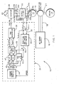
- the rotor angular position and velocity sensing system 10 comprises a motor 12 that is able to operate as a starter to start an engine 14, or as a generator to power a load (not shown). Because of this dual function, the motor 12 may be called a dynamoelectric machine. In one example, the motor 12 is a brushless motor that requires a controller to know a position of its rotor to operate.
- an AC power supply 16 provides an AC voltage along supply lines 18 to a rotating exciter 19.
- the AC power supply 16 provides three phases of AC power, however it is understood that other numbers of phases of AC power could be provided.
- the rotating exciter is connected to a shaft 21 that is also connected to the motor 12 and the engine 14.
- the AC voltage from the supply lines 18 induces an AC voltage along motor terminals 20a, 20b, and 20c.
- the induced voltage causes a current to flow through an output filter 22.
- a microprocessor 24 measures a voltage 26 and a current 28 from each of the terminals 20a, 20b, and 20c.
- a position and speed estimator 30 uses the voltage and current measurements to estimate a flux of the motor 12 and to estimate a rotor position 32 and a rotor angular velocity 34.
- an inverter 38 is turned ON.
- the microprocessor 24 processes the estimated rotor position 32 and estimated rotor angular velocity 34 to control a pulse width modulated (PWM) generator 36.
- Inverter 38 is coupled to the PWM generator 36 and converts a DC voltage from DC voltage supply lines 40 to AC. This voltage enables AC to flow through the output filter 22, which improves power quality by filtering out harmonics and reducing electromagnetic interference (EMI).
- EMI electromagnetic interference
- Figure 1 illustrates how the microprocessor 24 processes the estimated rotor position 32 and estimated rotor angular velocity 34 to control the inverter 38.
- An abc to d-q frame transformer 42 uses the estimated rotor position 32 to transform the current measurements 28 to a rotating d-q frame to obtain current values I d and Iq.
- a torque current profile generator 44 uses the estimated rotor angular velocity 34 to lookup reference current values I d * and I q *.
- Comparators 45 and 46 compare the transformed I d and Iq values to reference current values I d * and I q * to determine differences ⁇ I d and ⁇ I q between the transformed values and the reference values.
- Proportional and integral (PI) regulators 47 and 48 process the differences ⁇ I d and ⁇ I q using proportional and integral gains, and transmit an output signal to d-q to alpha-beta frame transformer 50, which converts the output into a stationary ⁇ - ⁇ frame to produce V alpha * and V beta * signals which are transmitted to the PWM generator 36.
- the PWM generator then controls the inverter 38 accordingly to produce a desired AC voltage.
- the output filter 22 comprises an inductor and a capacitor (not shown) in each phase.
- An input current I invt flows from the inverter 38 along the windings 23 a, 23b, and 23c to the output filter 22, and an output current I s flows from the output filter 22 along the terminals 20a, 20b, and 20c to the motor 12.
- the voltage measurements 26 and current measurements 28 are measured from each of the three terminals (20a, 20b, 20c) and each of the three windings (23a, 23b; 23c) in an a-b-c frame.
- the current measurement 28 is a measurement of the inverter output current I invt .
- the stationary ⁇ - ⁇ frame is a two phase frame and is a necessary step in calculating flux. Equation #3 is used to determine an ⁇ -axis voltage V ⁇ , a ⁇ -axis voltage V ⁇ , an ⁇ -axis current I ⁇ , and a ⁇ -axis current I ⁇ .
- ⁇ ext_ ⁇ ⁇ ext_ ⁇ 1 s ⁇ V ⁇ V ⁇ - R s 0 0 R s ⁇ I ⁇ I ⁇ - L q 0 0 L q ⁇ I ⁇ I ⁇
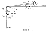
- Figure 2 illustrates a phasor diagram in the rotating d-q frame.
- Figure 2 illustrates the relationship between extended rotor flux and back EMF.
- a flux ⁇ s in the stator of the motor 12 is represented by a phasor 60.
- a stator current I s is represented by a phasor 62.
- a stator potential V s is represented by a phasor 64.
- a phasor 66 represents I s *L q where L q is a q-axis rotor inductance.
- a vector sum of the phasor 60, representing ⁇ s , and the phasor 66, representing I s *L q is an extended rotor flux ⁇ ext , which aligns with the d-axis of the d-q frame, and is represented by a phasor 67.
- a back electromotive force (EMF) E s is represented by a phasor 68. As shown in Figure 2 , the back EMF E s is perpendicular to the stator flux ⁇ s .
- the back EMF E s represented by the phasor 68, is a vector sum of the stator potential V s represented by phasor 64 and stator resistance potential drop I s *R s represented by a phasor 70, where R s is the stator resistance.
- An extended back electromotive force (EEMF), E ext , in the stator is represented by a phasor 72, and aligns with the q-axis of the d-q frame.
- I s *X q where X q is a q-axis stator reactance, is represented by a phasor 74.
- the extended back EMF represented by phasor 72 is a vector sum of E s represented by phasor 68 and I s *X q represented by a phasor 74.
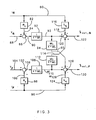
- Figure 3 illustrates a block diagram of the flux estimation algorithm shown in equation #5.
- a transformed measured current I ⁇ for the ⁇ -axis on a signal path 80 is multiplied by the stator resistance R s 82 to produce I ⁇ * R s on a signal path 84.
- a summer 86 subtracts I ⁇ * R s on the signal path 84 from the transformed potential V ⁇ on a signal path 88 to produce V ⁇ -( I ⁇ *R s ) on a signal path 90.
- V ⁇ - ( I ⁇ * R s ) on the signal path 90 is multiplied by a 1 s + ⁇ i first lag function 92 to produce first intermediate signal 1 s + ⁇ i ⁇ V ⁇ - I ⁇ * R s on a signal path 93.
- 1 s + ⁇ i ⁇ V ⁇ - I ⁇ * R s on the signal path 93 is multiplied by a ⁇ i s + ⁇ i second lag function 94 to produce ⁇ i s + ⁇ i ⁇ V ⁇ - I ⁇ * R s on a signal path 95.
- a transformed measured current I ⁇ for the ⁇ -axis on a signal path 96 is multiplied by the stator resistance R s 98 to produce I ⁇ * R s on a signal path 100.
- a summer 102 subtracts I ⁇ * R s on the signal path 100 from the transformed potential V ⁇ on a signal path 104 to produce V ⁇ - ( I ⁇ *R s ) on a signal path 106.
- V ⁇ -( I ⁇ *R s ) on the signal path 106 is multiplied by the 1 s + ⁇ i first lag function 108 to produce second intermediate signal 1 s + ⁇ i ⁇ V ⁇ - I ⁇ * R s on a signal path 110.
- the transformed measured current I ⁇ for the ⁇ -axis on the signal path 80 is also multiplied by a q-axis inductance L q 116 to produce I ⁇ *L q on the signal path 118.
- a summer 120 subtracts I ⁇ *L q on the signal path 118 from 1 s + ⁇ i ⁇ V ⁇ - I ⁇ * R s on the signal path 93 and adds ⁇ i s + ⁇ i ⁇ V ⁇ - I ⁇ * R s from the signal path 114 to produce 1 s + ⁇ i ⁇ V ⁇ - I ⁇ * R s + ⁇ i s + ⁇ i 2 ⁇ V ⁇ - I ⁇ * R s - I ⁇ * L q which corresponds to the extended rotor flux on the ⁇ -axis ⁇ ext_ ⁇ on the signal path 122.
- the " ⁇ "notation indicates that the extended rotor flux is an estimate based on measured values.
- the transformed measured current I ⁇ for the ⁇ -axis on the signal path 96 is also multiplied by a q-axis inductance L q 124 to produce I ⁇ *L q on the signal path 126.
- a summer 128 subtracts I ⁇ *L q on the signal path 126 from 1 s + ⁇ i ⁇ V ⁇ - I ⁇ * R s on the signal path 110 and subtracts ⁇ i s + ⁇ i ⁇ V ⁇ - I ⁇ * R s on the signal path 95 to produce 1 s + ⁇ i ⁇ V ⁇ - I ⁇ * R s - ⁇ i s + ⁇ i 2 ⁇ V ⁇ - I ⁇ * R s - I ⁇ * L q which corresponds to the extended rotor flux on the ⁇ -axis ⁇ est _ ⁇ on the signal path 130.
- the " ⁇ "notation indicates that the extended rotor flux is an estimate based on measured values
- the signal paths 95 and 114 cross-couple the signal paths 93 and 110.
- Equation #6 it would be possible to use an arctangent function to calculate a rotor position.
- Another option is to used a phase-locked loop (PLL) to derive position and angular velocity information.
- PLL phase-locked loop
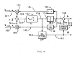
- Figure 4 is a block diagram illustrating how the microprocessor 24 uses a phase lock loop (PLL) to improve an estimate of rotor angular position and rotor angular velocity.
- the estimated ⁇ -axis extended rotor flux ⁇ ext _ ⁇ and the estimated ⁇ -axis extended rotor flux ⁇ ext _ ⁇ are applied to the signal paths 122 and 130.
- a multiplier 132 multiplies the estimated ⁇ -axis extended rotor flux ⁇ ext_ ⁇ with a feedback signal on a signal path 134 from a sine function 136 to produce an ⁇ -axis multiplier output signal on a signal path 138.
- a multiplier 140 multiplies the estimated ⁇ -axis extended rotor flux ⁇ ext_ ⁇ with a feedback signal on a signal path 142 from a cosine function 144 to produce a ⁇ -axis multiplier output signal on a signal path 146.
- a summer 148 subtracts the ⁇ -axis multiplier output signal on the signal path 138 from the ⁇ -axis multiplier output signal on the signal path 146 to produce a difference signal on a signal path 150.
- a proportional and integral (PI) regulator function 152 multiplies the difference signal on the signal path 150 by the function K p + K i s to produce a PI output signal on a signal path 154.
- K i is an integral gain of the PI function 152
- K p is a proportional gain of the PI function 152. Both K i and K p are constants based on a design of the system 10 as shown in Figure 1 .
- An integral function 156 multiplies the PI output signal on the signal path 154 by the function 1 s to produce an integration output signal on a signal path 158.
- the integration output signal on the signal path 158 is also fed into the inputs of the sine function 136 and the cosine function 144 to provide the PLL.
- a low pass filter (LPF) function 160 multiplies the PI output signal on the signal path 154 by a third lag function ⁇ c s + ⁇ c to produce an estimated rotor angular velocity ⁇ on a signal line 162, where ⁇ c is a corner or cutoff frequency of the LPF function 160.
- a low pass filter associated with the LPF function 160 is used to smooth out the signal on the signal line 154.
- the integration output signal on the signal path 158 is compensated by an offset ⁇ ⁇ to obtain a final estimated rotor angular position ⁇ .
- the offset ⁇ ⁇ can be a lump-sum error of miscellaneous delays, including delays introduced by the lag functions 92, 108 of Figure 3 , digital sampling delays introduced in measured voltage and current signals, and computation delays in the microprocessor 24 as shown in Figure 1 .
- a lookup table 164 may be used to compensate for this phase delay ⁇ ⁇ .
- the lookup table 164 generates a suitable phase delay ⁇ ⁇ on a signal path 166, and a summer 168 subtracts the phase delay ⁇ ⁇ from the integration output signal on the signal path 158 to produce the estimated rotor angular position ⁇ on a signal path 170.
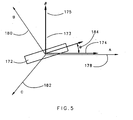
- Figure 5 illustrates how the ⁇ - ⁇ frame 173 comprises an ⁇ -axis 174 and a ⁇ -axis 175 that are perpendicular to each other.
- the ⁇ - ⁇ frame 173 aligns with a first phase 178, a second phase 180 and a third phase 182 of the system 10.
- a rotor 172 rotates, and its displacement from the ⁇ -axis is shown by the angle ⁇ 184, which is the rotor angular position to be estimated.
- the measured voltage 26 can be transformed to an alpha-beta frame.
- the transformed measured voltages V ⁇ and V ⁇ may be fed into the PLL as shown in Figure 4 to obtain the initial position angle ⁇ 0 .
- the voltage V ⁇ replaces the flux ⁇ ext_ ⁇ on the signal path 122
- the voltage V ⁇ replaces the flux ⁇ est_ ⁇ on the signal path 130 in Figure 4 .
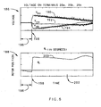
- Figure 6 illustrates an initial stator voltage and an initial rotor position as a function of time.
- the rotating exciter 19 is powered on by the ac power supply 16 in Figure 1 .
- Graph 186 illustrates a line-to-line voltage for each phase of the motor 12 as a function of time
- graph 188 illustrates an estimated rotor position as a function of time in the motor 12.
- the inverter 38 is OFF in the time periods shown in graphs 186 and 188.
- a voltage 190 corresponds to a V BC line-to-line voltage
- a voltage 192 corresponds to a V CA line-to-line voltage
- a voltage 194 corresponds to a V AB line-to-line voltage.
- An estimated rotor position ⁇ 0 200 corresponds to an angle of the rotor 172.
- the AC power supply 16 is OFF, and the three voltages 190, 192, and 194 are close to zero and the estimated rotor position ⁇ 0 200 cannot be used to determine actual rotor position. Specifically, if each of the voltages does not exceed a certain threshold, the extended rotor flux values are not applied to the phase lock loop to derive an estimated rotor angular position and an estimated rotor angular velocity, and the estimated rotor angular position and estimated rotor angular velocity are designated as invalid.
- the AC power supply 16 turns ON and current flows to the rotating exciter 19 through the supply line 18 in the system 10. During this period, an excitation magnetic field of the motor 12 is arising.
- the rising magnetic flux induces voltage at the terminals 20a, 20b, and 20c of the system 10.
- the magnitude of voltages 190, 192 and 194 is sufficient for the microprocessor 24 to be able to estimate rotor position ⁇ 0 200.
- graph 188 From time 198 to approximately time 202 the value of ⁇ 0 remains stable, and after time 202 the value starts to fluctuate due to a decaying voltage signal as shown in graph 186.
- This stable period demonstrates that a rotor position can be estimated from the voltages 190, 192, and 194 during the stable time period. If the rotor angular position cannot be determined within a predetermined period of time after the rotating exciter is turned on, the system indicates a fault condition. If the rotor angular position can be determined within a predetermined period of time after the rotating exciter is turned on, the inverter is turned on.
Landscapes
- Engineering & Computer Science (AREA)
- Power Engineering (AREA)
- Control Of Motors That Do Not Use Commutators (AREA)
- Control Of Ac Motors In General (AREA)
- Synchronous Machinery (AREA)
Claims (13)
- Schätzverfahren für eine Läuferdrehstellung und eine Läuferdrehzahl für eine dynamoelektrische Maschine (12), aufweisend die Schritte:(i) Messen eines AC-Stroms (28) und einer Spannung (26) für jede mehrerer Wicklungen, die mit einem Ständer der dynamoelektrischen Maschine gekoppelt sind;(ii) Transformieren der mehreren AC-Ströme und Spannungen in einem stationären Rahmen (α-β), um einen ersten transformierten Strom, einen zweiten transformierten Strom, eine erste transformierte Spannung und eine zweite transformierte Spannung zu erzeugen;(iii) Verarbeiten des ersten transformierten Stroms und der zweiten transformierten Spannung und Verarbeiten des zweiten transformierten Stroms und der zweiten transformierten Spannung, um ein erstes Zwischensignal (93) und ein zweites Zwischensignal (110) zu erhalten;(iv) Verarbeiten des ersten Zwischensignals und zweiten Zwischensignals, um einen ersten erweiterten Läuferflusswert (122) und einen zweiten erweiterten Läuferflusswert (130) zu erhalten; und(v) Anlegen des ersten erweiterten Läuferflusswerts und des zweiten erweiterten Läuferflusswerts an eine phasenverriegelte Schleife (132-158), um eine geschätzte Läuferdrehstellung und eine geschätzte Läuferdrehzahl für die dynamoelektrische Maschine abzuleiten;wobei der stationäre Rahmen ein Zwei-Phasen-α-β-Rahmen ist, der eine α-Achse und eine β-Achse aufweist, und wobei der erste transformierte Strom I α ist, der zweite transformierte Strom I β ist, die erste transformierte Spannung V α ist, die zweite transformierte Spannung V β ist, der erste erweiterte Läuferflusswert der α-Achse und der zweite erweiterte Läuferflusswert der β-Achse entspricht; und
wobei der Schritt des Verarbeitens des ersten transformierten Stroms und der zweiten transformierten Spannung und des Verarbeitens des zweiten transformierten Stroms und der zweiten transformierten Spannung, um ein erstes Zwischensignal und ein zweites Zwischensignal zu erhalten, die Schritte aufweist:Multiplizieren des ersten transformierten Stroms I α und des zweiten transformierten Stroms Iβ mit einem Widerstand R s des Ständers, um Signale I α*Rs , I β*Rs zu erzeugen;Subtrahieren der Signale I α*Rs, I β*Rs von der ersten transformierten Spannung V α und der zweiten transformierten Spannung Vβ, um Signale V α-I α*Rs, V β-I β*Rs zu erzeugen; undMultiplizieren der Signale V α-I α*Rs, V β-I β*Rs mit einer ersten Verzögerungsfunktion

 Multiplizieren der transformierten Ströme I α, Iβ mit einer q-Achsen-Induktivität Lq des Ständers, um Signale I α*Lq ,Iβ *Lq zu erzeugen;dadurch gekennzeichnet,
dass Schritt (iv) aufweist Kreuzkoppeln des ersten Zwischensignals und des zweiten Zwischensignals, um den ersten erweiterten Läuferflusswert (122) und den zweiten erweiterten Läuferflusswert (130) zu erhalten; und
dass der Schritt des Kreuzkoppelns und Verarbeitens des ersten Zwischensignals und des zweiten Zwischensignals aufweist die Schritte:Multiplizieren des ersten Zwischensignals


 Addieren des Signals
 Abziehen des Signals

- Verfahren gemäß Anspruch 1, wobei die ausgewählte Eckfrequenz ω i fest ist.
- Verfahren gemäß Anspruch 1 oder 2, wobei die ausgewählte Eckfrequenz ω i veränderlich ist.
- Verfahren gemäß einem der vorhergehenden Ansprüche, wobei der Schritt des Anlegens des ersten erweiterten Läuferflusswerts und des zweiten erweiterten Läuferflusswerts auf eine phasenverriegelte Schleife, um eine geschätzte Läuferdrehstellung und eine geschätzte Läuferdrehzahl für die dynamoelektrische Maschine abzuleiten, die Schritte aufweist:Multiplizieren des ersten erweiterten Läuferflusswerts mit einem Sinusfunktionrückkopplungssignal, um ein α-Achsen-Multiplikator-Ausgangssignal zu erzeugen;Multiplizieren des zweiten erweiterten Läuferflusswerts mit einem Cosinusfunktionrückkopplungsignal, um ein β-Achsen-Multiplikator-Ausgangssignal zu erzeugen;Abziehen des α-Achsen-Multiplikator-Ausgangssignals von dem β--Achsen-Multiplikator-Ausgangssignal, um ein Differenzsignal zu erzeugen;Multiplizieren des Differenzsignals mit einer Proportional- und Integral-Reglerfunktion
 Multiplizieren des PI-Ausgangssignals mit einer Integraffunktion
 Multiplizieren des Integrationsausgangssignals mit einer Sinusfunktion, um das Sinusrückkoppelsignal zu erzeugen; undMultiplizieren des Integrationsausgangssignals mit einer Cosinusfunktion, um das Cosinusrückkoppelsignal zu erzeugen, wobei die geschätzte Läuferdrehstellung und die geschätzte Läuferdrehzahl für die dynamoelektrische Maschine von Proportional- und Integral-Reglerfunktionsausgangssignal und dem Integrationsausgangssignal abgeleitet werden.
 - Verfahren gemäß Anspruch 4, weiter aufweisend die Schritte:Multiplizieren des Proportional- und Integralreglerfunktionsausgangssignals einer Tiefpassfilterfunktion
 Erzeugen einer Verzögerungskompensation basierend auf einem Wert der geschätzten Läuferdrehzahl; undAbziehen der Verzögerungskompensation vom Integrationsausgangssignal, um die geschätzte Läuferdrehstellung zu erzeugen.
 - Verfahren gemäß einem der vorhergehenden Ansprüche, weiter aufweisend den Schritt des Überwachens der Spannungen der mehreren Wicklungen, die mit dem Ständer der dynamoelektrischen Maschine gekoppelt sind, wobei wenn die Spannungen nicht einen bestimmten Schwellenwert überschreiten, der Schritt des Anlegens des ersten erweiterten Läuferflusswerts und des zweiten erweiterten Läuferflusswerts an eine phasenverriegelte Schleife, um eine geschätzte Läuferdrehstellung und eine geschätzte Läuferdrehzahl für die dynamoelektrische Maschine abzuleiten, nicht ausgeführt wird.
- Verfahren gemäß einem der vorhergehenden Ansprüche, weiter aufweisend den Schritt des Anzeigens einer Fehlerbedingung, wenn die Läuferdrehstellung für die dynamoelektrische Maschine nicht innerhalb einer vorbestimmten Zeitdauer bestimmt werden kann.
- Steuerungseinrichtung zum Schätzen einer Anfangsläuferdrehstellung und einer Läuferdrehzahl für eine dynamoelektrische Maschine (12) von einem Stillstand aufweisend:eine Bezugsrahmentransformationsfunktion zum Transformieren einer AC-Spannung (26) für jede mehrerer Wicklungen, die mit einem Ständer der dynamoelektrischen Maschine gekoppelt sind, in einem stationären Rahmen (α-β), um ein erstes transformiertes Spannung (Vα) und ein zweites transformiertes Spannung (Vβ) zu erzeugen; undeine phasenverriegelte Schleife (132-158), um eine geschätzte Läuferdrehstellung (Θ) und eine geschätzte Läuferdrehzahl für die dynamoelektrische Maschine von der ersten transformierten Spannung und der zweiten transformierten Spannung abzuleiten;wobei die Steuerungseinrichtung eingerichtet ist, um die AnfangsLäuferdrehstellung und die Läuferdrehzahl gemäß dem Verfahren nach Anspruch 1 zu schätzen.
- Steuerungseinrichtung gemäß Anspruch 8, wobei, wenn die Spannung der mehreren Wicklungen nicht einen bestimmten Schwellenwert überschreitet, die Steuerungseinrichtung die geschätzte Läuferdrehstellung und die geschätzte Läuferdrehzahl als ungültig bestimmt.
- Steuerungseinrichtung gemäß Anspruch 8 oder 9, wobei, wenn die Läuferdrehstellung für die dynamoelektrische Maschine nicht innerhalb einer vorbestimmten Zeitdauer bestimmt werden kann, nachdem ein drehender Erreger (19) aktiviert worden ist, das System einen Fehlerzustand anzeigt.
- Steuerung gemäß Anspruch 8, 9 oder 10, wobei, wenn die Läuferdrehstellung für die dynamoelektrische Maschine nicht innerhalb einer vorbestimmten Zeitdauer bestimmt werden kann, nachdem ein rotierender Erreger (19) aktiviert worden ist, ein Inverter eingeschaltet wird.
- Steuerung gemäß einem der Ansprüche 8 bis 11, wobei die phasenverriegelte Schleife, um einen geschätzten Läuferdrehstellungswert zu einem geschätzten Läufergeschwindigkeitswert für die dynamoelektrische Maschine von der ersten transformierten Spannung und der zweiten transformierten Spannung abzuleiten, aufweist:einen ersten Multiplikator (132) zum Multiplizieren der ersten transformierten Spannung mit einem Sinusfunktionsrückkoppelsignal, um ein α-Achsen-Multiplikatorausgangssignal zu erzeugen;einen zweiten Multiplikator (140) zum Multiplizieren der zweiten transformierten Spannung mit einem Sinusfunktionsrückkoppelsignal, um ein β-Achsen-Multiplikatorausgangssignal zu erzeugen;einen ersten Summierer (148) zum Abziehen des α-Achsen-Multiplikator-ausgangssignals von dem β-Achsen-Multiplikatorausgangssignal, um ein Differenzsignal zu erzeugen;eine Proportional- und Integral-Reglerfunktion (152) zum Multiplizieren des Differenzsignals mit einer Funktion
 eine Integralfunktion (156) zum Multiplizieren des PI-Ausgangssignals mit einer Integralfunktion
 eine Sinusfunktion (136) zum Multiplizieren des Integrationsausgangssignals mit einer Sinusfunktion, um das Sinusrückkoppelsignal zu erzeugen; undeine Cosinusfunktion (144) zum Multiplizieren des Integrationsausgangssignals mit einer Cosinusfunktion, um das Cosinusrückkoppelsignal zu erzeugen, wobei die geschätzte Läuferdrehstellung und die geschätzte Läuferdrehzahl für die dynamoelektrische Maschine von dem Proporational- und Integral-Reglerfunktionsausgangssignal und dem Integrationsausgangssignal abgeleitet werden.
 - Steuerung gemäß Anspruch 12, weiter aufweisend:einen Tiefpassfilter (160) zum Filtern des PI-Ausgangssignals mit einer Tiefpassfilterfunktion
 eine Nachschlagetabelle (164) zum Erzeugen einer Verzögerungskompensation basierend auf einem Wert der geschätzten Läuferdrehzahl; undeinen zweiten Summierer (168) zum Abziehen der Verzögerungskompensation von dem Integrationsausgangssignal, um die geschätzte Läuferdrehstellung zu erzeugen.
Applications Claiming Priority (1)
| Application Number | Priority Date | Filing Date | Title |
|---|---|---|---|
| US11/754,396 US7577545B2 (en) | 2007-05-29 | 2007-05-29 | Method and system for estimating rotor angular position and rotor angular velocity at low speeds or standstill |
Publications (3)
| Publication Number | Publication Date |
|---|---|
| EP1998435A2 EP1998435A2 (de) | 2008-12-03 |
| EP1998435A3 EP1998435A3 (de) | 2011-12-07 |
| EP1998435B1 true EP1998435B1 (de) | 2013-07-24 |
Family
ID=39639595
Family Applications (1)
| Application Number | Title | Priority Date | Filing Date |
|---|---|---|---|
| EP08251107.2A Active EP1998435B1 (de) | 2007-05-29 | 2008-03-27 | Verfahren und System zur Schätzung der Läuferwinkelposition und Läuferwinkelgeschwindigkeit bei geringer Geschwindigkeit bzw. Stillstand |
Country Status (2)
| Country | Link |
|---|---|
| US (1) | US7577545B2 (de) |
| EP (1) | EP1998435B1 (de) |
Cited By (3)
| Publication number | Priority date | Publication date | Assignee | Title |
|---|---|---|---|---|
| WO2023278532A1 (en) * | 2021-06-30 | 2023-01-05 | Texas Instruments Incorporated | A motor controller and a method for controlling a motor |
| US11728751B2 (en) | 2021-08-31 | 2023-08-15 | Texas Instruments Incorporated | Resynchronization of brushless DC motors |
| US11764710B2 (en) | 2021-06-30 | 2023-09-19 | Texas Instruments Incorporated | Automatic transition of motor controller from open-loop control to closed-loop control |
Families Citing this family (33)
| Publication number | Priority date | Publication date | Assignee | Title |
|---|---|---|---|---|
| EP2023479B1 (de) * | 2007-08-06 | 2014-04-16 | Baumüller Nürnberg Gmbh | System zur nahtlosen Geschwindigkeits- und/oder Lageermittlung einschließlich Stillstand bei einem Permanentmagnet-Läufer einer elektrischen Maschine |
| DK176958B1 (da) * | 2007-12-19 | 2010-07-26 | Vestas Wind Sys As | Generatorsystem med intelligent behandling af positionssignal |
| WO2009088908A1 (en) * | 2008-01-04 | 2009-07-16 | Delphi Technologies, Inc. | Methods and systems involving determining shaft velocity |
| JP5256009B2 (ja) * | 2008-12-12 | 2013-08-07 | 日立アプライアンス株式会社 | 磁石モータの速度制御装置 |
| US7804184B2 (en) * | 2009-01-23 | 2010-09-28 | General Electric Company | System and method for control of a grid connected power generating system |
| US8354817B2 (en) * | 2009-06-18 | 2013-01-15 | GM Global Technology Operations LLC | Methods and systems for diagnosing stator windings in an electric motor |
| DE102009027346A1 (de) * | 2009-06-30 | 2011-01-05 | Robert Bosch Gmbh | Verfahren und elektrische Schaltung zum Betreiben eines Elektromotors, insbesondere eines Stellmotors für eine Komponente einer Brennkraftmaschine |
| US8253365B2 (en) * | 2009-10-20 | 2012-08-28 | GM Global Technology Operations LLC | Methods and systems for performing fault diagnostics for rotors of electric motors |
| US8497698B2 (en) | 2010-08-11 | 2013-07-30 | GM Global Technology Operations LLC | Methods and systems for diagnosing faults for rotors of electric motors |
| KR101382305B1 (ko) * | 2010-12-06 | 2014-05-07 | 현대자동차주식회사 | 하이브리드 차량용 모터 제어 장치 |
| US8593095B2 (en) | 2011-05-24 | 2013-11-26 | Hamilton Sundstrand Corporation | Wound field synchronous machine rotor tracking using a carrier injection sensorless signal and exciter current |
| KR20130057902A (ko) * | 2011-11-24 | 2013-06-03 | 엘에스산전 주식회사 | 엘리베이터의 제어 방법, 엘리베이터 제어 장치 및 이를 이용한 엘리베이터 장치 |
| CN102651630B (zh) * | 2012-04-25 | 2015-07-15 | 浙江天煌科技实业有限公司 | 一种双馈交流励磁发电机定子磁链测量方法 |
| US8583265B1 (en) * | 2012-05-22 | 2013-11-12 | GM Global Technology Operations LLC | Methods, systems and apparatus for computing a voltage advance used in controlling operation of an electric machine |
| US8649887B2 (en) | 2012-05-22 | 2014-02-11 | GM Global Technology Operations LLC | Methods, systems and apparatus for implementing dithering in motor drive system for controlling operation of an electric machine |
| US9018881B2 (en) | 2013-01-10 | 2015-04-28 | GM Global Technology Operations LLC | Stator winding diagnostic systems and methods |
| US10158314B2 (en) * | 2013-01-16 | 2018-12-18 | Rockwell Automation Technologies, Inc. | Feedforward control of motor drives with output sinewave filter |
| US8928293B1 (en) * | 2013-08-02 | 2015-01-06 | Hamilton Sundstrand Corporation | Systems for wound field synchronous machines with zero speed rotor position detection during start for motoring and improved transient response for generation |
| TWI485973B (zh) * | 2013-08-08 | 2015-05-21 | Delta Electronics Inc | 馬達轉子位置的估測方法及裝置 |
| US10533413B2 (en) * | 2015-02-10 | 2020-01-14 | Evolution Engineering Inc. | Method and apparatus for determining rotor position in a fluid pressure pulse generator |
| JP6614825B2 (ja) * | 2015-06-30 | 2019-12-04 | 日立ジョンソンコントロールズ空調株式会社 | 電力変換装置およびモータ駆動装置、冷凍装置 |
| US9705438B2 (en) | 2015-07-14 | 2017-07-11 | Infineon Technologies Austria Ag | Controller for a free-running motor |
| ITUB20155550A1 (it) | 2015-11-13 | 2017-05-13 | Piaggio & C Spa | Metodo di controllo di una unita di propulsione per bicicletta a pedalata assistita e relativa bicicletta a pedalata assistita |
| CN105515486B (zh) * | 2015-12-03 | 2017-12-29 | 北京机械设备研究所 | 一种永磁同步电机转子磁极位置实时补偿校正方法 |
| CN105322846B (zh) * | 2015-12-23 | 2017-12-29 | 北京机械设备研究所 | 一种基于锁相环的永磁同步电机转子磁极位置检测装置 |
| US9985565B2 (en) | 2016-04-18 | 2018-05-29 | Rockwell Automation Technologies, Inc. | Sensorless motor drive vector control with feedback compensation for filter capacitor current |
| US10020766B2 (en) | 2016-11-15 | 2018-07-10 | Rockwell Automation Technologies, Inc. | Current control of motor drives with output sinewave filter |
| US10097117B2 (en) * | 2016-12-15 | 2018-10-09 | Caterpillar Inc. | Adjustable pulse injection in electric machine control |
| CN106655919B (zh) * | 2016-12-26 | 2019-02-22 | 北京机械设备研究所 | 一种基于无位置传感器的无刷直流电机换相电路 |
| JP6351913B1 (ja) * | 2017-03-21 | 2018-07-04 | 三菱電機株式会社 | 磁極位置検出装置及びモータ制御装置 |
| CN110971167B (zh) * | 2019-12-24 | 2021-10-12 | 江苏大学 | 基于检波滤波器的变漏磁电机无位置传感器控制方法 |
| US11404983B2 (en) * | 2020-01-07 | 2022-08-02 | Infineon Technologies Austria Ag | Catch spin method for permanent magnet synchronous motor with sensorless field oriented control |
| DE102022110316A1 (de) * | 2022-04-28 | 2023-11-02 | Schaeffler Technologies AG & Co. KG | Steuereinrichtung, elektrische Maschine und Verfahren zur Steuerung und/oder Regelung der Bestromung einer elektrischen Maschine |
Family Cites Families (15)
| Publication number | Priority date | Publication date | Assignee | Title |
|---|---|---|---|---|
| US5051680A (en) | 1989-12-08 | 1991-09-24 | Sundstrand Corporation | Simple starting sequence for variable reluctance motors without rotor position sensor |
| US5461293A (en) | 1993-05-12 | 1995-10-24 | Sundstrand Corporation | Rotor position detector |
| IT1261597B (it) | 1993-09-30 | 1996-05-23 | Gate Spa | Procedimento e sistema per il controllo di un motore elettrico brushless. |
| GB9525952D0 (en) | 1995-12-19 | 1996-02-21 | Switched Reluctance Drives Ltd | Sensorless rotor position monitoring in reluctance machines |
| CN1520024A (zh) | 1998-07-16 | 2004-08-11 | ������������ʽ���� | 不带位置传感器的电动机的控制方法及其控制装置 |
| US6163127A (en) | 1999-11-22 | 2000-12-19 | General Motors Corporation | System and method for controlling a position sensorless permanent magnet motor |
| US6388419B1 (en) * | 2000-09-01 | 2002-05-14 | Ford Global Technologies, Inc. | Motor control system |
| EP1198059A3 (de) | 2000-10-11 | 2004-03-17 | Matsushita Electric Industrial Co., Ltd. | Verfahren und Vorrichtung für eine positionssensorlose Motorregelung |
| JP3707535B2 (ja) * | 2000-12-18 | 2005-10-19 | 株式会社安川電機 | 誘導電動機の速度推定値補正方法およびその装置 |
| US6667597B2 (en) * | 2001-12-20 | 2003-12-23 | Texas Instruments Incorporated | Method of extending the operating speed range of a rotor flux based MRAS speed observer in a three phase AC induction motor |
| JP3695436B2 (ja) | 2002-09-18 | 2005-09-14 | 株式会社日立製作所 | 位置センサレスモータ制御方法および装置 |
| US6924617B2 (en) * | 2003-06-23 | 2005-08-02 | General Motors Corporation | Position sensorless control algorithm for AC machine |
| US7026772B2 (en) | 2004-01-14 | 2006-04-11 | International Rectifier Corporation | Position sensorless drive for permanent magnet synchronous motors |
| US7072790B2 (en) * | 2004-08-12 | 2006-07-04 | Hamilton Sundstrand Corporation | Shaft sensorless angular position and velocity estimation for a dynamoelectric machine based on extended rotor flux |
| US7339344B2 (en) * | 2005-08-25 | 2008-03-04 | International Rectifier Corporation | Self tuning method and apparatus for permanent magnet sensorless control |
-
2007
- 2007-05-29 US US11/754,396 patent/US7577545B2/en active Active
-
2008
- 2008-03-27 EP EP08251107.2A patent/EP1998435B1/de active Active
Cited By (4)
| Publication number | Priority date | Publication date | Assignee | Title |
|---|---|---|---|---|
| WO2023278532A1 (en) * | 2021-06-30 | 2023-01-05 | Texas Instruments Incorporated | A motor controller and a method for controlling a motor |
| US11764710B2 (en) | 2021-06-30 | 2023-09-19 | Texas Instruments Incorporated | Automatic transition of motor controller from open-loop control to closed-loop control |
| US11916496B2 (en) | 2021-06-30 | 2024-02-27 | Texas Instruments Incorporated | Motor controller and a method for controlling a motor |
| US11728751B2 (en) | 2021-08-31 | 2023-08-15 | Texas Instruments Incorporated | Resynchronization of brushless DC motors |
Also Published As
| Publication number | Publication date |
|---|---|
| US20080300820A1 (en) | 2008-12-04 |
| US7577545B2 (en) | 2009-08-18 |
| EP1998435A2 (de) | 2008-12-03 |
| EP1998435A3 (de) | 2011-12-07 |
Similar Documents
| Publication | Publication Date | Title |
|---|---|---|
| EP1998435B1 (de) | Verfahren und System zur Schätzung der Läuferwinkelposition und Läuferwinkelgeschwindigkeit bei geringer Geschwindigkeit bzw. Stillstand | |
| EP2191564B1 (de) | Motorregler zur bestimmung einer position eines rotors eines wechselstrommotors, wechselstrommotorsystem und verfahren zur bestimmung einer position eines rotors eines wechselstrommotors | |
| CN102751936B (zh) | 电力变换装置、电动机驱动系统 | |
| US8217605B2 (en) | Motor controller for determining a position of a rotor of an AC motor, AC motor system, and method of determining a position of a rotor of an AC motor | |
| US7772789B2 (en) | Motor controller | |
| EP0944164B1 (de) | Sensorloses steurungsverfahren und permanenterregte synchronmotorvorrichtung | |
| EP2061147B1 (de) | Erkennung der anfänglichen Rotorposition und Anlaufsystem für eine dynamoelektrische Maschine | |
| JP5130031B2 (ja) | 永久磁石モータの位置センサレス制御装置 | |
| JP3668870B2 (ja) | 同期電動機駆動システム | |
| US6396229B1 (en) | Method of estimating a rotor position of synchronous motor, method of controlling synchronous motor with no position sensor and a controller of synchronous motor | |
| KR101046802B1 (ko) | 교류 회전기의 제어 장치 및 이 제어 장치를 사용한 교류회전기의 전기적 정수 측정 방법 | |
| US7072790B2 (en) | Shaft sensorless angular position and velocity estimation for a dynamoelectric machine based on extended rotor flux | |
| EP2698916A2 (de) | Motorregelungsvorrichtung und Motorregelungsverfahren | |
| EP1808956B1 (de) | Steuervorrichtung und Steuersystem für einen elektrischen Motor | |
| EP3252942A1 (de) | Wandlersteuerungsvorrichtung und antriebssystem | |
| JP2002291283A (ja) | 同期電動機の磁極位置推定方法および制御装置 | |
| JP2002320398A (ja) | Dcブラシレスモータのロータ角度検出装置 | |
| JP2008220096A (ja) | 同期電動機のセンサレス制御装置 | |
| JP3707528B2 (ja) | 交流電動機の制御方法およびその制御装置 | |
| EP3358743B1 (de) | Stromumwandlungsvorrichtung und automatisches einstellverfahren dafür | |
| JP2002136197A (ja) | センサレスベクトル制御装置およびその方法 | |
| EP1729405B1 (de) | Gerät zur Drehzahlregelung eines feldorientiert geregelten Wechselstrommotors | |
| JP2580101B2 (ja) | 誘導電動機制御システムの制御演算定数設定方法 | |
| EP1073193B1 (de) | Steuerverfahren eines sensorlosen Induktionsmotors | |
| Bisheimer et al. | Permanent magnet motor control in full speed range without mechanical sensors |
Legal Events
| Date | Code | Title | Description |
|---|---|---|---|
| PUAI | Public reference made under article 153(3) epc to a published international application that has entered the european phase |
Free format text: ORIGINAL CODE: 0009012 |
|
| AK | Designated contracting states |
Kind code of ref document: A2 Designated state(s): AT BE BG CH CY CZ DE DK EE ES FI FR GB GR HR HU IE IS IT LI LT LU LV MC MT NL NO PL PT RO SE SI SK TR |
|
| AX | Request for extension of the european patent |
Extension state: AL BA MK RS |
|
| REG | Reference to a national code |
Ref country code: DE Ref legal event code: R079 Free format text: PREVIOUS MAIN CLASS: H02P0021000000 Ipc: H02P0021060000 |
|
| PUAL | Search report despatched |
Free format text: ORIGINAL CODE: 0009013 |
|
| AK | Designated contracting states |
Kind code of ref document: A3 Designated state(s): AT BE BG CH CY CZ DE DK EE ES FI FR GB GR HR HU IE IS IT LI LT LU LV MC MT NL NO PL PT RO SE SI SK TR |
|
| AX | Request for extension of the european patent |
Extension state: AL BA MK RS |
|
| RIC1 | Information provided on ipc code assigned before grant |
Ipc: H02P 21/14 20060101ALI20111031BHEP Ipc: H02P 21/06 20060101AFI20111031BHEP |
|
| 17P | Request for examination filed |
Effective date: 20120330 |
|
| AKX | Designation fees paid |
Designated state(s): FR GB |
|
| REG | Reference to a national code |
Ref country code: DE Ref legal event code: R108 Effective date: 20120816 |
|
| GRAP | Despatch of communication of intention to grant a patent |
Free format text: ORIGINAL CODE: EPIDOSNIGR1 |
|
| GRAS | Grant fee paid |
Free format text: ORIGINAL CODE: EPIDOSNIGR3 |
|
| GRAA | (expected) grant |
Free format text: ORIGINAL CODE: 0009210 |
|
| AK | Designated contracting states |
Kind code of ref document: B1 Designated state(s): FR GB |
|
| REG | Reference to a national code |
Ref country code: GB Ref legal event code: FG4D |
|
| PLBE | No opposition filed within time limit |
Free format text: ORIGINAL CODE: 0009261 |
|
| STAA | Information on the status of an ep patent application or granted ep patent |
Free format text: STATUS: NO OPPOSITION FILED WITHIN TIME LIMIT |
|
| 26N | No opposition filed |
Effective date: 20140425 |
|
| REG | Reference to a national code |
Ref country code: FR Ref legal event code: PLFP Year of fee payment: 9 |
|
| REG | Reference to a national code |
Ref country code: FR Ref legal event code: PLFP Year of fee payment: 10 |
|
| REG | Reference to a national code |
Ref country code: FR Ref legal event code: PLFP Year of fee payment: 11 |
|
| P01 | Opt-out of the competence of the unified patent court (upc) registered |
Effective date: 20230522 |
|
| PGFP | Annual fee paid to national office [announced via postgrant information from national office to epo] |
Ref country code: GB Payment date: 20260219 Year of fee payment: 19 |
|
| PGFP | Annual fee paid to national office [announced via postgrant information from national office to epo] |
Ref country code: FR Payment date: 20260219 Year of fee payment: 19 |