EP1073193B1 - Steuerverfahren eines sensorlosen Induktionsmotors - Google Patents
Steuerverfahren eines sensorlosen Induktionsmotors Download PDFInfo
- Publication number
- EP1073193B1 EP1073193B1 EP00115629A EP00115629A EP1073193B1 EP 1073193 B1 EP1073193 B1 EP 1073193B1 EP 00115629 A EP00115629 A EP 00115629A EP 00115629 A EP00115629 A EP 00115629A EP 1073193 B1 EP1073193 B1 EP 1073193B1
- Authority
- EP
- European Patent Office
- Prior art keywords
- high frequency
- zero
- voltage
- stator
- magnetic field
- Prior art date
- Legal status (The legal status is an assumption and is not a legal conclusion. Google has not performed a legal analysis and makes no representation as to the accuracy of the status listed.)
- Expired - Lifetime
Links
Images


Classifications
-
- H—ELECTRICITY
- H02—GENERATION; CONVERSION OR DISTRIBUTION OF ELECTRIC POWER
- H02P—CONTROL OR REGULATION OF ELECTRIC MOTORS, ELECTRIC GENERATORS OR DYNAMO-ELECTRIC CONVERTERS; CONTROLLING TRANSFORMERS, REACTORS OR CHOKE COILS
- H02P21/00—Arrangements or methods for the control of electric machines by vector control, e.g. by control of field orientation
- H02P21/14—Estimation or adaptation of machine parameters, e.g. flux, current or voltage
- H02P21/141—Flux estimation
-
- H—ELECTRICITY
- H02—GENERATION; CONVERSION OR DISTRIBUTION OF ELECTRIC POWER
- H02P—CONTROL OR REGULATION OF ELECTRIC MOTORS, ELECTRIC GENERATORS OR DYNAMO-ELECTRIC CONVERTERS; CONTROLLING TRANSFORMERS, REACTORS OR CHOKE COILS
- H02P21/00—Arrangements or methods for the control of electric machines by vector control, e.g. by control of field orientation
- H02P21/04—Arrangements or methods for the control of electric machines by vector control, e.g. by control of field orientation specially adapted for very low speeds
-
- H—ELECTRICITY
- H02—GENERATION; CONVERSION OR DISTRIBUTION OF ELECTRIC POWER
- H02P—CONTROL OR REGULATION OF ELECTRIC MOTORS, ELECTRIC GENERATORS OR DYNAMO-ELECTRIC CONVERTERS; CONTROLLING TRANSFORMERS, REACTORS OR CHOKE COILS
- H02P21/00—Arrangements or methods for the control of electric machines by vector control, e.g. by control of field orientation
- H02P21/14—Estimation or adaptation of machine parameters, e.g. flux, current or voltage
- H02P21/18—Estimation of position or speed
-
- H—ELECTRICITY
- H02—GENERATION; CONVERSION OR DISTRIBUTION OF ELECTRIC POWER
- H02P—CONTROL OR REGULATION OF ELECTRIC MOTORS, ELECTRIC GENERATORS OR DYNAMO-ELECTRIC CONVERTERS; CONTROLLING TRANSFORMERS, REACTORS OR CHOKE COILS
- H02P21/00—Arrangements or methods for the control of electric machines by vector control, e.g. by control of field orientation
- H02P21/24—Vector control not involving the use of rotor position or rotor speed sensors
- H02P21/26—Rotor flux based control
-
- H—ELECTRICITY
- H02—GENERATION; CONVERSION OR DISTRIBUTION OF ELECTRIC POWER
- H02P—CONTROL OR REGULATION OF ELECTRIC MOTORS, ELECTRIC GENERATORS OR DYNAMO-ELECTRIC CONVERTERS; CONTROLLING TRANSFORMERS, REACTORS OR CHOKE COILS
- H02P6/00—Arrangements for controlling synchronous motors or other dynamo-electric motors using electronic commutation dependent on the rotor position; Electronic commutators therefor
- H02P6/14—Electronic commutators
- H02P6/16—Circuit arrangements for detecting position
- H02P6/18—Circuit arrangements for detecting position without separate position detecting elements
- H02P6/185—Circuit arrangements for detecting position without separate position detecting elements using inductance sensing, e.g. pulse excitation
-
- H—ELECTRICITY
- H02—GENERATION; CONVERSION OR DISTRIBUTION OF ELECTRIC POWER
- H02P—CONTROL OR REGULATION OF ELECTRIC MOTORS, ELECTRIC GENERATORS OR DYNAMO-ELECTRIC CONVERTERS; CONTROLLING TRANSFORMERS, REACTORS OR CHOKE COILS
- H02P2203/00—Indexing scheme relating to controlling arrangements characterised by the means for detecting the position of the rotor
- H02P2203/11—Determination or estimation of the rotor position or other motor parameters based on the analysis of high frequency signals
Definitions
- the present invention relates to The present invention refers to a control method for sensorless drives with induction motors.
- induction motor drives are widely used in electric traction systems and in several industrial applications, such as machine tools, pumps, conveyor belts and others, wherein they are progressively replacing the traditional direct current motor drives, thanks to their improved robustness, reduced maintenance and to the lower production costs.
- induction motor drives may be divided into two categories: low performance drives and high performance drives.
- speed regulators may be open-loop type (constant Volt/Hertz technique) or closed-loop type (slip control technique), while flux and torque control are performed by scalar control approaches, acting only on the amplitude of the electric variables.
- scalar control approaches require the knowledge of the amplitude of the stator flux in order to determine the stator voltage as function of the frequency and the speed.
- induction motor vector control techniques In high performance induction motor drives speed and position controllers are of the closed loop type, while flux and torque control are performed by vector control approaches, acting on both the amplitude and the angular position of the rotating vectors representing the electric variables.
- field orientation is today the most widely diffused approach. It performs an independent regulation of flux and torque by acting on the stator current components according to a two phase rotating reference frame, synchronous with the rotor flux. Control techniques based on the field orientation principle require the knowledge of both the amplitude and the angular position of the rotor flux.
- the amplitude and the angular position of both the stator flux and the rotor flux can be obtained from the amplitude and the angular position of the airgap flux by adding proper corrective terms depending on the stator current and the induction machine parameters.
- the amplitude and the angular position of the airgap flux could be, in theory, directly measured using Hall effect flux sensors. Such sensors, however, do not provide in practice the required precision; further, their instalment inside the machine is often complex.
- the amplitude and the position of the rotor flux can be determined directly from measured stator voltages and currents (direct field orientation) or, more commonly, in an indirect way, by means of a mathematical model of the motor (indirect field orientation). This last technique is, by far, the most used, even though it requires an angular position transducer of the machine shaft, with a resolution equal at least to 8 bits, and although the so obtained results are extremely sensitive to rotor resistance variations caused by the temperature.
- More sophisticated sensorless type control techniques based on injecting suitable test signals and on measuring the high frequency current harmonics allow to noticeably reduce the minimum motor speed allowed by the control; however also such techniques do not completely solve the problem of torque and flux control at very low or zero speeds.
- the motor control at very low or zero speed is required very frequently and, in particular, it is useful in electric traction applications, in robotics, in many machine tools of the new generation, and, in general, in all those applications where it is required to balance a load at standstill or to bring a shaft back to a given position.
- a method for controlling an induction motor is known from US 5 559 419.
- a purpose of the present invention is therefore to realize a control system for low performance induction motor drives able to overcome the above mentioned disadvantages and, in particular, to define a control system to realise "sensorless type” electrical drive means, based on the constant Volt/Hertz technique, or on the slip control technique, able to properly work at very low speeds or even at zero speed.
- Another purpose of the present invention is to realize a control system for high performance induction motor drives able to overcome the above mentioned disadvantages and, in particular, to define a control system to realise "sensorless type” electrical drive means, based on the direct field orientation approach, able to properly work at very low speeds or even at zero speed.
- Another purpose of the present invention is to define a method for the measurement of the amplitude and/or the angular position of the airgap flux in induction motor drives, able to properly work at any stator voltage frequency and, in particular, at very low and zero frequency.
- Another purpose of the present invention is to indicate a system for the measurement of the amplitude and/or the angular position of the airgap flux, to be used in the realisation of high performance and low performance sensorless induction motor drives.
- a further purpose of the present invention is to define some control schemes for induction motor drives using said method and system of measurement, able to correctly work at very low and zero speed, irrespectively from load changes. Moreover, to indicate some exemplary implementation schemes using conventional circuits and computing devices easy to install and to use, at low costs compared to standard techniques and in consideration of the attained advantages.
- T3 indicates the third harmonic component of the airgap flux TF
- BS indicates the feeding bus of the inverter PWM
- ST1, ST2, ST3 indicate the windings of the three phases of the stator ST of the electric machine
- TV indicates a voltage transducer
- TA a current transducer
- PB indicates a band-pass filter
- EB indicates a notch filter
- CA indicates an electronic device, or a software procedure, to evaluate the amplitude FA of the airgap flux TF
- CP indicates an electronic device ,or a software procedure, to evaluate the angular position FP of the airgap flux TF
- RC indicates a stator current control system
- B0 indicates an electronic device, or a software procedure, to perform the machine control according to the constant Volt/Hertz technique
- XF indicates an electronic device, or a software procedure, to perform the machine control according to the field orientation principle.
- Induction motors in normal operating conditions and rated flux, work in the bend area of the curve B-H of the ferromagnetic material which represents the core; further, the ferromagnetic core of the machine is more saturated along the flux direction.
- the saturation causes a local anisotropy of the induction machine which, by itself, has a non salient magnetic structure.
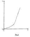
- the space distribution of the airgap flux TF is not perfectly sinusoidal, due to saturation, with a harmonic content characterised by the presence of odd and zero sequence harmonics, but strongly influenced by the third harmonic component T3.
- the third harmonic T3 of the flux at the air gap TF induces, in the three phases F1, F2, F3 of the stator windings ST1, ST2, ST3, three third harmonic voltages V31, V32, V33, which are in phase among them, and form a zero sequence three phase voltage.
- Variation of the third harmonic flux T3 as a function of the main flux TF can be determined experimentally and is not linear, as shown in figure 1.
- the high frequency rotating field produces a change of the saturation level of the magnetic circuit of the machine which is a function of the position taken during its rotation; in particular, the saturation level will be maximum when such a high frequency field will be aligned and phased with the main field, it will be at the value determined only by the main airgap flux when the high frequency field is in quadrature with the main field, and finally it will be minimum when the high frequency flux is aligned in counter-phase with the main field.
- the zero sequence component of the flux at the air gap TF also includes a high frequency harmonic FOA at a frequency equal to the difference between the frequency of the additional voltage VHF and the frequency of the main rotating magnetic field.
- maximum and minimum points in the waveform of FOA respectively correspond to maximum and minimum values of the saturation level, that, in turn, occur when respectively the high frequency field is aligned in phase and in phase opposition with the main rotating field.
- the high frequency flux is 90° leading the additional high frequency voltage VHF, it is possible to univocally determine the angular position FP of the airgap flux TF, from the known angular position of the voltage VHF, at the time instants in which maximum, minimum and zero points of FOA take place.
- the amplitude of the zero sequence voltage harmonic VOA is strictly proportional to the amplitude of the zero sequence airgap flux component FOA, and related to the amplitude of the airgap flux TF by mean of the function drawn in Fig. 2. Moreover VOA is 90° leading the zero sequence airgap flux component FOA, thus the position FP of the airgap flux TF can be also univocally determined, from the known angular position of the voltage VHF, at the time instants in which maximum, minimum and zero points of VOA take place.
- a high frequency zero sequence component IOA of the stator current is generated, having the same frequency of the zero sequence airgap flux component FOA. Due to the features of the high frequency zero sequence current path, the amplitude of the zero sequence current component IOA is proportional to the amplitude of the zero sequence voltage component VOA. Moreover, a constant phase displacement exists between IOA and VOA, enabling the determination of the angular position FP of the airgap flux TF, from the known angular position of the voltage VHF, at the time instants in which maximum, minimum and zero points of IOA take place.
- the third harmonic phase voltages V31, V32, V33 and the high frequency zero sequence harmonic components can be picked up directly between the terminals of the stator ST and the star centre N of the stator windings, without any significant phase error. Then, the total zero sequence voltage VSM can be obtained by adding the three phase voltages of the machine at any time instant.
- the global zero sequence voltage VSM can be picked up between the star centre N of the stator windings ST1, ST2, ST3 and the central point O of the capacitors C1, C2 of the direct current bus BS, which feeds the inverter PWM with width impulse modulation.
- a voltage proportional to the global zero voltage VSM can be picked up between a fictitious star centre NF, obtained by connecting a star of three equal impedances in any point of the cable connecting the inverter at the machine, and the central point O of the capacitors C1, C2 of the direct current bus BS, which feeds the inverter PWM.
- a further alternative is to measure the total zero sequence current ISM.
- the third harmonic component of the zero sequence voltage VSM which is the output of the voltage transducer TV, or of the zero sequence current ISM, is eliminated by a band-pass filter PB that also eliminates further high frequency harmonics, as those produced by the inverter PWM and by the rotor slots, as well as high frequency noises.
- the amplitude FA of the airgap flux TF is obtained, using a computing device CA, from the amplitude of the voltage VOA, that is the output of the band-pass filter PB, according to the experimental function shown in Fig. 2.
- the angular position FP of the airgap flux TF is obtained, using a computing device CP, from the known angular position of the voltage VHF, by detecting the maximum, minimum and zero points of the voltage VOA.
- the angular position FP of the airgap flux TF can be obtained, using a suitable computing device, by integration of the difference between the known angular speed of the voltage VHF and the measurable angular speed of the zero frequency voltage component VOA.
- a high performance induction motor drive can be experimentally implemented in a simple and inexpensive way, as the one illustrated in the schematic diagram of figure 4, that exploits the method and the system for the measurement of the angular position of the airgap flux, according to the present invention.
- the injection of the set of three high frequency voltages VHF, the measurement of the zero sequence component VSM from the stator voltages V31, V32, V33, the filtering operation of the high frequency harmonics, the measurement of the maximum, minimum and zero points, using the computing device CP, can be carried out utilizing low cost analogue circuits and there are various schemes which can be realised, as the one of figure 4, which represents a non limiting example of embodiment of the system according to the invention. Note that in such a scheme also the block XF is shown, which performs the field oriented control of the motor in a predetermined reference system, as well as the block RC that performs the stator current control.
- the signal VSM obtained at the output of TV is then filtered and amplified in order to achieve a good signal/noise ratio.
- the block CP performs the estimation of the angular position of the airgap flux according to the invention.
- the estimated airgap flux angular position FP is then sent to the block XF performing the field orientation.
- the block XF receives as inputs the reference stator current components ID and IQ, then it makes a transformation from the two phase rotating reference frame synchronous with the flux, to a three phase fixed reference system, in order to generate the stator current reference IR.
- the actual stator current is measured by the current transducer TA, while the notch filter EB is used to eliminate the high frequency components in the current feedback loop.
- the current regulator device RC manages the reference stator voltage VR in order to minimise the error between the reference stator current IR and the feedback signal IF.
- stator reference voltage VR is then added to the high frequency component VHF and, finally, sent to the inverter PWM.
- a low performance induction motor drive can be also experimentally implemented in a simple and inexpensive way, as the one illustrated in the schematic diagram of figure 3, which represents a non limiting example of embodiment of the system according to the invention, that exploits the method and the system for the measurement of the amplitude of the airgap flux object of the present invention.
- CT, RT torque control
- XF field orientation
- TA, EB, RC stator current control
- CP angular position of the airgap flux
- the control of the amplitude of the airgap flux is performed by mean of the flux regulator RF that generates the stator voltage amplitude reference value VS, in order to minimise the error between the flux reference FR and the estimated flux amplitude FA.
- the inverter PWM reference signal VR is generated by the block BO according, for example, to a constant volt/hertz technique.
Claims (9)
- Verfahren zum Steuern von Elektroantrieben mit Induktionsmotoren, wobei der Induktionsmotor einen Stator (ST) mit mehreren Statorwicklungen (ST1, ST2, ST3), einen in dem Stator (ST) drehbar angeordneten Rotor und einen ferromagnetischen Kern umfasst, wobei das Verfahren die Schritte umfasst: Betreiben des Motors mit einem Hauptmagnetfeld in einem Zustand magnetischer Sättigung, wobei ein Luftspaltfluss (TF) eine räumliche Verteilung mit einem Gehalt an Oberwellen hat, der zumindest eine harmonische Komponente (T3) umfasst, die in den Statorwicklungen (ST1, ST2, ST3) harmonische Phasenspannungen (V31, V32, V33) hervorrufen, die eine Statornullspannung (VSM) oder einen -strom (ISM) bilden, Überlagern des Hauptdrehfeldes mit einem hochfrequenten Drehfeld, das erzeugt wird, indem eine Gruppe direkt oder invers symmetrischer Hochfrequenzspannungen (VHF) oder -strömen (IHF) zu den üblichen Statorphasenspannungen des Motors addiert wird, wodurch eine Veränderung des Sättigungsgrads des ferromagnetischen Kerns des Induktionsmotors verursacht und eine hochfrequente Nullkomponente (T3) des Luftspaltflusses (TF) erzeugt wird, die in den Statorwicklungen (ST1, ST2, ST3) hochfrequente harmonische Nullspannungs- (VSM) oder -stromkomponenten (ISM) hervorruft, wobei die hochfrequenten Nullspannungs- (VSM) oder -stromkomponente (ISM) Funktionen der Relativpositionen sind, die durch die zusätzliche Gruppe der hochfrequenten Spannungen (VHF) oder Ströme (IHF) und des Hauptdrehfeldes (MRF) eingenommen werden, sodass, wenn sich die zusätzliche Gruppe der Spannungen (VHF) und Ströme (IHF) mit dem Hauptdrehfeld (MRF) in Phase befindet, ein Maximum des Sättigungsgrads des ferromagnetischen Kerns des Motors einstellt, welches das Auftreten eines lokalen Minimums an der hochfrequenten Nullkomponente (T3) des Luftspaltflusses (TF) verursacht, das als lokales Maximum an den hervorgerufenen hochfrequenten Statornullspannungs- (VSM) oder -stromkomponenten (ISM) reflektiert wird; wobei sich das Verfahren weiterhin auszeichnet durch:Feststellen der Nullspannung oder des Nullspannungsstroms,Messen der Winkelstellung und/oder der Amplitude des Hauptmagnetflusses in dem Luftspalt gegenüber den hochfrequenten harmonischen Nullspannungs- oder - stromkomponenten
- Steuerverfahren gemäß Anspruch 1, dadurch gekennzeichnet, dass es ferner den Schritt des Filterns und Verstärkens der Statomullphasenspannung (VSM) mittels Filter- und Verstärkungsmittel, um ein Verhältnis zwischen Signal und Rauschen zu erhalten, und die Verwendung eines Sperrfilters (EB) umfasst, der mit einem ersten Signalverarbeitungs- und Steuerblock (RC) verbunden ist, um unerwünschte hochfrequente Komponenten des Rückführkreises (FA, FP) der Stromsignale zu unterbinden.
- Steuerverfahren gemäß Anspruch 2, dadurch gekennzeichnet, dass der Rückführkreis (FA, FP) zumindest eine Steuereinheit (RF) der Stromsignale, die ein Referenzsignal (VS) zu einem zweiten Verarbeitungs- und Steuerblock (BO) sendet, um einen Referenzwert (VR) bezüglich eines festen Achsensystems zu erzeugen, und eine elektronische inverterartige Vorrichtung (PWM) umfasst, die den Referenzwert (VR) empfängt, der mit der Gruppe der hochfrequenten Spannungen (VHF) addiert wurde.
- Steuerverfahren gemäß Anspruch 3, gekennzeichnet durch den Schritt, in dem die Gruppe der hochfrequenten Spannungen (VHF) zu einem Spannungsreferenzsignal (VR) oder zu einem Output der Stromsteuereinheit (RF) addiert wird.
- Steuerverfahren gemäß Anspruch 1, dadurch gekennzeichnet, dass es einen Schritt zum Messen der Amplitude einer Komponente (VOA) der hochfrequenten Statornullphasenspannung (VSM), die eine Frequenz aufweist, die gleich der Differenz zwischen der Frequenz des zusätzlichen Magnetfeldes, das durch die zusätzliche Gruppe hochfrequenter Spannungen (VHF) erzeugt wird, und der Frequenz des Hauptdrehfeldes (MRF) ist, und einem Schritt umfasst, um die Amplitude einer Luftspaltflusskomponente (FOA) aus der Amplitude der Komponente (VOA) der hochfrequenten Statomullphasenspannung (VSM) zu ermitteln.
- Steuerverfahren gemäß Anspruch 5, dadurch gekennzeichnet, dass die Winkelstellung des Luftspaltflusses (TF) durch Integrieren der Differenz aus der Winkelfrequenz der zusätzlichen Gruppe der hochfrequenten Spannungen (VHF) und der hochfrequenten Statomullphasenspannung (VSM), die eine Frequenz besitzt, die gleich der Differenz aus der Frequenz des zusätzlichen Magnetfeldes und des Hauptdrehfeldes ist, bestimmt wird.
- Steuerverfahren gemäß Anspruch 5, dadurch gekennzeichnet, dass die Winkelstellung des Luftspaltflusses (TF) durch Ermitteln der Winkelstellung der zusätzlichen Gruppe der hochfrequenten Spannungen (VHF) in den Augenblicken bestimmt wird, in denen ein Maximum, Minimum und der Nulldurchgang bei der Statomullphasenspannung (VSM) erfolgt, die eine Frequenz aufweist, die gleich der Differenz aus dem zusätzlichen Magnetfeld, das von der zusätzlichen Gruppe der hochfrequenten Spannungen (VHF) hervorgerufen wird, und der Frequenz des Hauptdrehfeldes ist.
- Steuerverfahren gemäß Anspruch 5, dadurch gekennzeichnet, dass eine vollständige Statornullphasenspannung (VSM), die eine dritte harmonische Spannungskomponente und hochfrequente harmonische Komponenten umfasst, als arithmetischer Mittelwert aus den harmonischen Phasenspannungen (V31, V32, V33) erhalten wird, wobei die vollständige Statomullphasenspannung (VSM) durch Messen einer Spannung zwischen einem Sternzentrum (N) der Statorwindungen (ST1, ST2, ST3) und einem Mittelpunkt (O) erhalten wird, der zwischen zwei Kapazitäten (C1, C2) liegt, die entlang einer direkten elektrischen Stromleitung (ES) verbunden sind, die eine elektronische inverterartige Vorrichtung (PVM) versorgen.
- Steuerverfahren gemäß Anspruch 8, dadurch gekennzeichnet, dass der vollständige Statomullphasenstrom (ISM) direkt durch entsprechende Sensoren oder indirekt durch Messen eines Nullspannungsabfalls an beliebigen Punkten einer Verbindungsleitung zwischen der elektronischen inverterartigen Vorrichtung (PWM) und dem Elektromotor bestimmt wird, wobei der Spannungsabfall durch Bestimmung der Spannung zwischen einem Sternzentrum (NF), das durch Verbinden eines Drei-Impedanzsterns über eine Parallelleitung zu den Versorgungsleitungen des Motors erhalten wird, und einem Mittelpunkt (O) gemessen wird, der zwischen zwei Kapazitäten (C1, C2) liegt, die entlang einer direkten elektrischen Stromleitung (DC) verbunden sind, die eine elektronische inverterartige Vorrichtung (PWM) versorgen.
Priority Applications (1)
| Application Number | Priority Date | Filing Date | Title |
|---|---|---|---|
| DK00115629T DK1073193T3 (da) | 1999-07-29 | 2000-07-20 | Fremgangsmåde til styring af en sensorlös induktionsmotor |
Applications Claiming Priority (4)
| Application Number | Priority Date | Filing Date | Title |
|---|---|---|---|
| IT1999TO000669A IT1310649B1 (it) | 1999-07-29 | 1999-07-29 | Sistema e metodo di controllo per azionamenti elettrici con motoreasincrono. |
| ITTO990669 | 1999-07-29 | ||
| US09/501,056 US6559618B1 (en) | 1999-07-29 | 2000-02-09 | System and method of control for sensorless induction motor drives |
| US501056 | 2000-02-09 |
Publications (3)
| Publication Number | Publication Date |
|---|---|
| EP1073193A2 EP1073193A2 (de) | 2001-01-31 |
| EP1073193A3 EP1073193A3 (de) | 2001-05-30 |
| EP1073193B1 true EP1073193B1 (de) | 2005-04-06 |
Family
ID=11418006
Family Applications (1)
| Application Number | Title | Priority Date | Filing Date |
|---|---|---|---|
| EP00115629A Expired - Lifetime EP1073193B1 (de) | 1999-07-29 | 2000-07-20 | Steuerverfahren eines sensorlosen Induktionsmotors |
Country Status (7)
| Country | Link |
|---|---|
| US (1) | US6559618B1 (de) |
| EP (1) | EP1073193B1 (de) |
| AT (1) | ATE292856T1 (de) |
| DE (1) | DE60019208T8 (de) |
| DK (1) | DK1073193T3 (de) |
| ES (1) | ES2239973T3 (de) |
| IT (1) | IT1310649B1 (de) |
Families Citing this family (3)
| Publication number | Priority date | Publication date | Assignee | Title |
|---|---|---|---|---|
| US7778053B2 (en) * | 2006-02-13 | 2010-08-17 | American Superconductor Corp. | Power system having a voltage regulator with a notch filter |
| US10738784B2 (en) | 2017-09-14 | 2020-08-11 | Unico, Llc | Power-loss ridethrough system and method |
| CN113965125B (zh) * | 2021-10-12 | 2024-01-16 | 上海飒智智能科技有限公司 | 一种智能移动机器人轮毂电机伺服驱动器并联控制方法 |
Family Cites Families (11)
| Publication number | Priority date | Publication date | Assignee | Title |
|---|---|---|---|---|
| US4011489A (en) * | 1974-11-20 | 1977-03-08 | General Electric Company | Apparatus for regulating magnetic flux in an AC motor |
| US4445080A (en) | 1981-11-25 | 1984-04-24 | The Charles Stark Draper Laboratory, Inc. | System for indirectly sensing flux in an induction motor |
| US5254918A (en) | 1990-06-08 | 1993-10-19 | Victor Company Of Japan, Ltd. | Detection of position of rotor in brushless dc motor |
| US5334923A (en) * | 1990-10-01 | 1994-08-02 | Wisconsin Alumni Research Foundation | Motor torque control method and apparatus |
| US5272429A (en) * | 1990-10-01 | 1993-12-21 | Wisconsin Alumni Research Foundation | Air gap flux measurement using stator third harmonic voltage and uses |
| ATE131668T1 (de) | 1991-04-11 | 1995-12-15 | Elin Energieanwendung | Verfahren und schaltungsanordnungen zur bestimmung maschinenbezogener elektromagnetischer und mechanischer zustandsgrössen an über umrichter gespeisten elektrodydynamischen drehfeldmaschinen |
| TW291623B (de) | 1993-04-28 | 1996-11-21 | Hitachi Ltd | |
| US5559419A (en) | 1993-12-22 | 1996-09-24 | Wisconsin Alumni Research Foundation | Method and apparatus for transducerless flux estimation in drives for induction machines |
| US5585709A (en) * | 1993-12-22 | 1996-12-17 | Wisconsin Alumni Research Foundation | Method and apparatus for transducerless position and velocity estimation in drives for AC machines |
| KR100264916B1 (ko) * | 1997-08-05 | 2000-09-01 | 설승기 | 고주파 신호를 이용한 유도 전동기의 자속 기준 제어 방법 |
| US6137258A (en) * | 1998-10-26 | 2000-10-24 | General Electric Company | System for speed-sensorless control of an induction machine |
-
1999
- 1999-07-29 IT IT1999TO000669A patent/IT1310649B1/it active
-
2000
- 2000-02-09 US US09/501,056 patent/US6559618B1/en not_active Expired - Fee Related
- 2000-07-20 EP EP00115629A patent/EP1073193B1/de not_active Expired - Lifetime
- 2000-07-20 DE DE60019208T patent/DE60019208T8/de not_active Expired - Fee Related
- 2000-07-20 DK DK00115629T patent/DK1073193T3/da active
- 2000-07-20 ES ES00115629T patent/ES2239973T3/es not_active Expired - Lifetime
- 2000-07-20 AT AT00115629T patent/ATE292856T1/de not_active IP Right Cessation
Also Published As
| Publication number | Publication date |
|---|---|
| DE60019208T2 (de) | 2006-02-09 |
| EP1073193A3 (de) | 2001-05-30 |
| IT1310649B1 (it) | 2002-02-19 |
| US6559618B1 (en) | 2003-05-06 |
| DE60019208T8 (de) | 2006-04-27 |
| ATE292856T1 (de) | 2005-04-15 |
| EP1073193A2 (de) | 2001-01-31 |
| ITTO990669A1 (it) | 2001-01-29 |
| ES2239973T3 (es) | 2005-10-16 |
| ITTO990669A0 (it) | 1999-07-29 |
| DK1073193T3 (da) | 2005-08-08 |
| DE60019208D1 (de) | 2005-05-12 |
Similar Documents
| Publication | Publication Date | Title |
|---|---|---|
| Wang et al. | Rotor position estimation for permanent magnet synchronous motor using saliency-tracking self-sensing method | |
| EP1998435B1 (de) | Verfahren und System zur Schätzung der Läuferwinkelposition und Läuferwinkelgeschwindigkeit bei geringer Geschwindigkeit bzw. Stillstand | |
| Consoli et al. | A new zero-frequency flux-position detection approach for direct-field-oriented-control drives | |
| EP1876702B1 (de) | Motorreglungsvorrichtung | |
| Degner et al. | Using multiple saliencies for the estimation of flux, position, and velocity in AC machines | |
| EP2061147B1 (de) | Erkennung der anfänglichen Rotorposition und Anlaufsystem für eine dynamoelektrische Maschine | |
| US8330403B2 (en) | Method for determining the position of the flux vector of a motor | |
| US7180262B2 (en) | Control system and method for electric drives with a.c. motors | |
| KR100264916B1 (ko) | 고주파 신호를 이용한 유도 전동기의 자속 기준 제어 방법 | |
| KR101046802B1 (ko) | 교류 회전기의 제어 장치 및 이 제어 장치를 사용한 교류회전기의 전기적 정수 측정 방법 | |
| US20090200974A1 (en) | Sensorless control apparatus of synchronous machine | |
| JP2008220096A (ja) | 同期電動機のセンサレス制御装置 | |
| Saitoh et al. | Adaptive signal injection method combined with EEMF-based position sensorless control of IPMSM drives | |
| JP5120621B2 (ja) | 永久磁石形同期電動機の制御装置 | |
| Brandstetter et al. | Sensorless control of permanent magnet synchronous motor using voltage signal injection | |
| US9331618B2 (en) | Magnetic pole position detector for synchronous motor | |
| JP4154149B2 (ja) | ベクトル制御インバータ装置 | |
| JP5396741B2 (ja) | 永久磁石形同期電動機の制御装置 | |
| Hammel et al. | Operating point dependent anisotropies and assessment for position-sensorless control | |
| EP1073193B1 (de) | Steuerverfahren eines sensorlosen Induktionsmotors | |
| CN111512539A (zh) | 无旋转传感器地确定感应式电机的转子位置的方法和无旋转传感器地调节交流电机的装置 | |
| JP2002272195A (ja) | 同期電動機の制御装置 | |
| Jing et al. | Optimization of speed loop control technology for permanent magnet synchronous motor servo system | |
| JP3405115B2 (ja) | 電動機の電気角偏差の測定方法 | |
| JP3287147B2 (ja) | 誘導電動機の制御方法 |
Legal Events
| Date | Code | Title | Description |
|---|---|---|---|
| PUAI | Public reference made under article 153(3) epc to a published international application that has entered the european phase |
Free format text: ORIGINAL CODE: 0009012 |
|
| AK | Designated contracting states |
Kind code of ref document: A2 Designated state(s): AT BE CH CY DE DK ES FI FR GB GR IE IT LI LU MC NL PT SE |
|
| AX | Request for extension of the european patent |
Free format text: AL;LT;LV;MK;RO;SI |
|
| PUAL | Search report despatched |
Free format text: ORIGINAL CODE: 0009013 |
|
| AK | Designated contracting states |
Kind code of ref document: A3 Designated state(s): AT BE CH CY DE DK ES FI FR GB GR IE IT LI LU MC NL PT SE |
|
| AX | Request for extension of the european patent |
Free format text: AL;LT;LV;MK;RO;SI |
|
| 17P | Request for examination filed |
Effective date: 20010821 |
|
| 17Q | First examination report despatched |
Effective date: 20011219 |
|
| AKX | Designation fees paid |
Free format text: AT BE CH CY DE DK ES FI FR GB GR IE IT LI LU MC NL PT SE |
|
| AXX | Extension fees paid |
Free format text: AL PAYMENT 20010821;LT PAYMENT 20010821;LV PAYMENT 20010821;RO PAYMENT 20010821;SI PAYMENT 20010821 |
|
| GRAP | Despatch of communication of intention to grant a patent |
Free format text: ORIGINAL CODE: EPIDOSNIGR1 |
|
| RTI1 | Title (correction) |
Free format text: METHOD OF CONTROL FOR SENSORLESS INDUCTION MOTOR DRIVES |
|
| GRAS | Grant fee paid |
Free format text: ORIGINAL CODE: EPIDOSNIGR3 |
|
| GRAA | (expected) grant |
Free format text: ORIGINAL CODE: 0009210 |
|
| AK | Designated contracting states |
Kind code of ref document: B1 Designated state(s): AT BE CH CY DE DK ES FI FR GB GR IE IT LI LU MC NL PT SE |
|
| AX | Request for extension of the european patent |
Extension state: AL LT LV RO SI |
|
| PG25 | Lapsed in a contracting state [announced via postgrant information from national office to epo] |
Ref country code: AT Free format text: LAPSE BECAUSE OF FAILURE TO SUBMIT A TRANSLATION OF THE DESCRIPTION OR TO PAY THE FEE WITHIN THE PRESCRIBED TIME-LIMIT Effective date: 20050406 Ref country code: FI Free format text: LAPSE BECAUSE OF FAILURE TO SUBMIT A TRANSLATION OF THE DESCRIPTION OR TO PAY THE FEE WITHIN THE PRESCRIBED TIME-LIMIT Effective date: 20050406 Ref country code: LI Free format text: LAPSE BECAUSE OF FAILURE TO SUBMIT A TRANSLATION OF THE DESCRIPTION OR TO PAY THE FEE WITHIN THE PRESCRIBED TIME-LIMIT Effective date: 20050406 Ref country code: BE Free format text: LAPSE BECAUSE OF FAILURE TO SUBMIT A TRANSLATION OF THE DESCRIPTION OR TO PAY THE FEE WITHIN THE PRESCRIBED TIME-LIMIT Effective date: 20050406 Ref country code: NL Free format text: LAPSE BECAUSE OF FAILURE TO SUBMIT A TRANSLATION OF THE DESCRIPTION OR TO PAY THE FEE WITHIN THE PRESCRIBED TIME-LIMIT Effective date: 20050406 Ref country code: CH Free format text: LAPSE BECAUSE OF FAILURE TO SUBMIT A TRANSLATION OF THE DESCRIPTION OR TO PAY THE FEE WITHIN THE PRESCRIBED TIME-LIMIT Effective date: 20050406 |
|
| REG | Reference to a national code |
Ref country code: GB Ref legal event code: FG4D |
|
| REG | Reference to a national code |
Ref country code: CH Ref legal event code: EP |
|
| REG | Reference to a national code |
Ref country code: IE Ref legal event code: FG4D |
|
| REF | Corresponds to: |
Ref document number: 60019208 Country of ref document: DE Date of ref document: 20050512 Kind code of ref document: P |
|
| PG25 | Lapsed in a contracting state [announced via postgrant information from national office to epo] |
Ref country code: SE Free format text: LAPSE BECAUSE OF FAILURE TO SUBMIT A TRANSLATION OF THE DESCRIPTION OR TO PAY THE FEE WITHIN THE PRESCRIBED TIME-LIMIT Effective date: 20050706 Ref country code: GR Free format text: LAPSE BECAUSE OF FAILURE TO SUBMIT A TRANSLATION OF THE DESCRIPTION OR TO PAY THE FEE WITHIN THE PRESCRIBED TIME-LIMIT Effective date: 20050706 |
|
| PG25 | Lapsed in a contracting state [announced via postgrant information from national office to epo] |
Ref country code: LU Free format text: LAPSE BECAUSE OF NON-PAYMENT OF DUE FEES Effective date: 20050720 Ref country code: CY Free format text: LAPSE BECAUSE OF FAILURE TO SUBMIT A TRANSLATION OF THE DESCRIPTION OR TO PAY THE FEE WITHIN THE PRESCRIBED TIME-LIMIT Effective date: 20050720 Ref country code: IE Free format text: LAPSE BECAUSE OF NON-PAYMENT OF DUE FEES Effective date: 20050720 |
|
| PG25 | Lapsed in a contracting state [announced via postgrant information from national office to epo] |
Ref country code: MC Free format text: LAPSE BECAUSE OF NON-PAYMENT OF DUE FEES Effective date: 20050731 |
|
| REG | Reference to a national code |
Ref country code: DK Ref legal event code: T3 |
|
| PG25 | Lapsed in a contracting state [announced via postgrant information from national office to epo] |
Ref country code: PT Free format text: LAPSE BECAUSE OF FAILURE TO SUBMIT A TRANSLATION OF THE DESCRIPTION OR TO PAY THE FEE WITHIN THE PRESCRIBED TIME-LIMIT Effective date: 20050908 |
|
| LTIE | Lt: invalidation of european patent or patent extension |
Effective date: 20050406 |
|
| NLV1 | Nl: lapsed or annulled due to failure to fulfill the requirements of art. 29p and 29m of the patents act | ||
| REG | Reference to a national code |
Ref country code: CH Ref legal event code: PL |
|
| REG | Reference to a national code |
Ref country code: ES Ref legal event code: FG2A Ref document number: 2239973 Country of ref document: ES Kind code of ref document: T3 |
|
| PLBE | No opposition filed within time limit |
Free format text: ORIGINAL CODE: 0009261 |
|
| STAA | Information on the status of an ep patent application or granted ep patent |
Free format text: STATUS: NO OPPOSITION FILED WITHIN TIME LIMIT |
|
| ET | Fr: translation filed | ||
| 26N | No opposition filed |
Effective date: 20060110 |
|
| REG | Reference to a national code |
Ref country code: IE Ref legal event code: MM4A |
|
| PGFP | Annual fee paid to national office [announced via postgrant information from national office to epo] |
Ref country code: DK Payment date: 20090714 Year of fee payment: 10 Ref country code: ES Payment date: 20090812 Year of fee payment: 10 Ref country code: FR Payment date: 20090710 Year of fee payment: 10 |
|
| PGFP | Annual fee paid to national office [announced via postgrant information from national office to epo] |
Ref country code: GB Payment date: 20090715 Year of fee payment: 10 Ref country code: DE Payment date: 20090716 Year of fee payment: 10 |
|
| GBPC | Gb: european patent ceased through non-payment of renewal fee |
Effective date: 20100720 |
|
| PG25 | Lapsed in a contracting state [announced via postgrant information from national office to epo] |
Ref country code: IT Free format text: LAPSE BECAUSE OF NON-PAYMENT OF DUE FEES Effective date: 20090720 |
|
| REG | Reference to a national code |
Ref country code: FR Ref legal event code: ST Effective date: 20110331 |
|
| PG25 | Lapsed in a contracting state [announced via postgrant information from national office to epo] |
Ref country code: DE Free format text: LAPSE BECAUSE OF NON-PAYMENT OF DUE FEES Effective date: 20110201 |
|
| REG | Reference to a national code |
Ref country code: DE Ref legal event code: R119 Ref document number: 60019208 Country of ref document: DE Effective date: 20110201 |
|
| PG25 | Lapsed in a contracting state [announced via postgrant information from national office to epo] |
Ref country code: FR Free format text: LAPSE BECAUSE OF NON-PAYMENT OF DUE FEES Effective date: 20100802 |
|
| PG25 | Lapsed in a contracting state [announced via postgrant information from national office to epo] |
Ref country code: GB Free format text: LAPSE BECAUSE OF NON-PAYMENT OF DUE FEES Effective date: 20100720 |
|
| PGFP | Annual fee paid to national office [announced via postgrant information from national office to epo] |
Ref country code: IT Payment date: 20090717 Year of fee payment: 10 |
|
| PGRI | Patent reinstated in contracting state [announced from national office to epo] |
Ref country code: IT Effective date: 20110616 |
|
| REG | Reference to a national code |
Ref country code: ES Ref legal event code: FD2A Effective date: 20110818 |
|
| REG | Reference to a national code |
Ref country code: DK Ref legal event code: EBP |
|
| PG25 | Lapsed in a contracting state [announced via postgrant information from national office to epo] |
Ref country code: ES Free format text: LAPSE BECAUSE OF NON-PAYMENT OF DUE FEES Effective date: 20100721 |
|
| PG25 | Lapsed in a contracting state [announced via postgrant information from national office to epo] |
Ref country code: DK Free format text: LAPSE BECAUSE OF NON-PAYMENT OF DUE FEES Effective date: 20100802 |
|
| PGRI | Patent reinstated in contracting state [announced from national office to epo] |
Ref country code: IT Effective date: 20110616 |