EP1998402A1 - Speisesystem insbesondere zum Empfang von über Satellit ausgestrahlten Fernseh- und/oder Rundfunkprogrammen - Google Patents
Speisesystem insbesondere zum Empfang von über Satellit ausgestrahlten Fernseh- und/oder Rundfunkprogrammen Download PDFInfo
- Publication number
- EP1998402A1 EP1998402A1 EP08008694A EP08008694A EP1998402A1 EP 1998402 A1 EP1998402 A1 EP 1998402A1 EP 08008694 A EP08008694 A EP 08008694A EP 08008694 A EP08008694 A EP 08008694A EP 1998402 A1 EP1998402 A1 EP 1998402A1
- Authority
- EP
- European Patent Office
- Prior art keywords
- waveguide
- housing
- circuit board
- printed circuit
- auskoppelstifte
- Prior art date
- Legal status (The legal status is an assumption and is not a legal conclusion. Google has not performed a legal analysis and makes no representation as to the accuracy of the status listed.)
- Granted
Links
Images


Classifications
-
- H—ELECTRICITY
- H01—ELECTRIC ELEMENTS
- H01P—WAVEGUIDES; RESONATORS, LINES, OR OTHER DEVICES OF THE WAVEGUIDE TYPE
- H01P1/00—Auxiliary devices
- H01P1/16—Auxiliary devices for mode selection, e.g. mode suppression or mode promotion; for mode conversion
- H01P1/161—Auxiliary devices for mode selection, e.g. mode suppression or mode promotion; for mode conversion sustaining two independent orthogonal modes, e.g. orthomode transducer
Definitions
- the invention relates to a feed system according to the preamble of claim 1.
- Feed systems are commonly used to receive televisions and radio programs broadcast via geostationary-positioned satellites. In this case, analog or digitally broadcast programs can be received in such feed systems.
- Such feed systems include a so-called OMT, so called a so-called orthomode transducer (called in German Orthormenkoppler or polarization switch), the receiving side a horn, for example, a so-called grooved horn, which is usually at least slightly conical and compared to its opening area in a round in cross-section or, for example, square waveguide passes.
- OMT so-called a so-called orthomode transducer
- horn for example, a so-called grooved horn, which is usually at least slightly conical and compared to its opening area in a round in cross-section or, for example, square waveguide passes.
- Coupling pins are provided in the waveguide, namely a first coupling pin for receiving an electromagnetic wave radiated in a first plane of polarization and a further, offset thereto lying second coupling pin for receiving an electromagnetic wave which propagates in a plane perpendicular to the first plane of polarization second polarization plane.
- the electromagnetic wave of the first and second polarization plane can be coupled and fed to a downstream converter (LNB), in which a corresponding processing for frequency conversion of the satellite received signals.
- the LNB again comprises a separate housing, ie a housing which is separate from the feed system and which is mounted laterally or transversely to the waveguide of the OMT.
- Corresponding constructions are for example from EP 0 611 488 or the EP 0 815 611 B1 known.
- Vorveröttingungen coupling pins are arranged parallel to each other. Between you is a lying in the same plane of the coupling pins reflector pin provided. At the end of the short-circuited waveguide, a phase rotator is provided which rotates and reflects a plane of polarization left through 90 °, which is why the closer to the waveguide end coupling pin can be arranged lying in the same plane as the remote coupling pin for receiving the first polarization plane.
- the board of the converter which is housed in a box-shaped housing, be laterally arranged on the waveguide of the OMT, so that the coupling pins perpendicular to the Porterplatinenebene project through the housing of the LNB and through corresponding openings in the waveguide protrude from the OMT. Therefore, the corresponding construction of the lateral attachment, so the eccentric attachment of the LNB's side to the median plane of the waveguide is due.
- the waveguide attached laterally to the housing of the LNB is integrally formed with the corresponding housing plate of the LNB.
- the unitary housing construction basically has the same construction, such that the waveguide of the OMT is offset laterally relative to the housing receptacle connected in one piece therewith.
- twin horn which is constructed so that the distance between the central axes of the two waveguides are less than 55 mm to each other.
- this requires special designs, especially a special tool, if such a twin horn is to be produced as a casting.
- a multi antenna with several parallel arranged horn constructions and waveguides is also from the DE 20 2005 012 610 known.
- this prior publication describes only a very specific arrangement with very specific lateral center distances between the individual OMT's, which are only suitable for a specific multifeed reception for certain satellites geo-stationary positioned orbit.
- the predetermined axial distance is only optimal with respect to a particular position on the earth, at another point nearer or farther away from the equator, the construction given here due to the lack of adaptation of the side distance of the individual waveguide leads to a deterioration of the received signal.
- a feed system with an associated horn, in particular grooved horn, and an OMT is proposed, which builds considerably narrower compared to conventional devices with very good reception performance.
- the overall width of the device housing, including the horn and the housing of the LNB's may have a width, for example, is less than 45 mm. This makes this feed system suitable for multifeed, for example for receiving programs transmitted via the Astra satellite (19.2 ° East) and the Hotbird satellite (13 ° East), using a mirror diameter (parabolic antenna) of only 60 cm.
- the housing of the converter including the housing of the horn and the waveguide as a common casting produced.
- a structure can be realized, which allows a necessary demoulding. Only a separate housing cover is necessary to close the converter housing.
- This housing cover can be made as a casting or as a separate sheet metal part or in another suitable manner.
- two signal output pins can be designed as PCB pins. That is, in the waveguide tube of the waveguide only two openings are provided which form a connection to the housing interior of the LNB with the printed circuit board provided there, the at least two Signalauskoppelite, preferably in the form of two Porterplatinenzapfen project through this opening into the interior of the waveguide.
- the two mutually parallel Auskoppel reconstructe are arranged transversely and in particular perpendicular to the printed circuit board, that can be guided laterally through corresponding openings in the waveguide.
- the two Auskoppel reconstructe are aligned perpendicular to each other, while for example at least one of Auskoppelmase is designed as an angle pin, so that the actual, projecting into the waveguide Auskoppelabterrorism is perpendicular to the other leg of the angularly shaped coupling pin What this angle-shaped decoupling pin is then ultimately held on the circuit board.
- corresponding recesses in the wall of the waveguide can be introduced so that the printed circuit board is positioned in a tight position for this purpose can be so that the housing of the waveguide and the converter are arranged as symmetrical and central to each other, so if possible with no or only slightest lateral offset to allow a total of narrow housing construction.
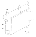
- FIG. 1 is a first embodiment of the invention for a feed system 1 for receiving television and / or Radio programs broadcast over a geostationary satellite.
- the feed system 1 has an overall housing 3, which consists at least predominantly of a cast part.
- the feed system 1 comprises a horn 5, which merges via a funnel-shaped tapering section into a waveguide 7, which is closed at one end opposite the horn 5 with a waveguide wall 9.
- This OMT Organic Metal-to-Metamiconductor
- This OMT Organic Metal-to-Metamiconductor
- the waveguide 7 will at least slightly taper from the cavity 5 to its waveguide end 9 in order to be able to perform demolding.
- the horn 5 is formed in the embodiment shown as a so-called groove horn 5 ', i. it comprises in the illustrated embodiment, three concentric grooves 5 ", which are arranged to form annular grooves 11, in such a way that from the outside inwards extending each concentric inner groove is offset in the direction of the subsequent waveguide 7. Thus leave prevent unwanted wall currents to avoid cross-polarization couplings.
- the housing tube of the waveguide 7 and the horn 5 are preferably part of the overall housing 9, which can be closed, for example, along a sectional plane 13 by means of a housing cover 3 '.
- the cutting plane 13 is in shown embodiment, based on the width B of the housing arranged eccentrically.
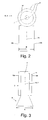
- FIG. 2 is a schematic front view and in FIG. 3 a schematic plan view of the embodiment according to FIG. 1 shown.
- the maximum width BH of the horn in the illustrated embodiment corresponds approximately to the width B of the converter housing 12.
- the central axis 7 'of the waveguide 7 and the horn 5 is arranged so that this central axis 7' is located in the median plane 15, which is central and parallel to the large opposite side walls 12a and 12b of the converter housing 12, wherein the converter housing 12th , as stated, is part of the overall housing 3 and in the process the one large side wall 12b is essentially formed by the cover 3 '.
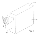
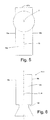
- a modification is shown insofar as the waveguide 7 quasi not positioned on the upper longitudinal or front side 12c and formed with the converter housing 12 as an integral overall housing, but quasi exits on the front side 12d of the converter housing 12 and in the forward projecting horn 5 passes.
- the waveguide 7, as it were is no longer directly recognizable from its contour towards the outside in the overall box-shaped converter housing 12, which thus simultaneously represents the overall housing.
- the arrangement is such that the central axis 7 'of the waveguide 7 and the horn 5 is located in the center plane 15, which is parallel and central to the side walls 12 a.
- the central axis 7 'of the waveguide 7 and the horn 5 can be arranged to the center plane 15 through the converter housing 12 with a small lateral offset S.
- this lateral offset S should be so small that, starting from a predetermined horn 5 and in particular groove horn 5 'optimized for the reception of electromagnetic waves, the overall width B of the overall housing 3 should not or substantially not increase, ie preferably 45 mm and less For example, below 40 mm, for example, by 39 mm or even less should have.
- the central axis 7 'of the waveguide does not necessarily have to lie in the middle plane 15 parallel to the large side surfaces 12a of the converter housing.
- these deviations are preferably less than 20%, in particular less than 10%, or even less than 5% of the maximum outer diameter of the horn 5.
- FIG. 8 is now in schematic cross-sectional representation and in FIG. 9 in longitudinal section along the median plane 15, a first embodiment in a schematic detail view reproduced.
- a printed circuit board 19 is disposed in the chamber 20, that is, in the chamber 20, which is formed by the converter housing 12.
- the printed circuit board 19 preferably accommodates the entire circuit arrangement for the converter circuit (LNB).
- FIG. 9 shows, in the axial longitudinal direction of the waveguide 7 between the two freely projecting Auskoppelstatten 22 and 23 in the same plane as the coupling pins 22, 23, a reflector 27 in the form of a reflector pin 27 'is arranged.
- a phase rotator 31 is still provided, which reflects the second plane of polarization in the reflection at the waveguide end 9, ie on the waveguide wall 9, by 90 °, so that these perpendicular to the first plane of polarization electromagnetic wave on the waveguide end closer second coupling pin 23 can be coupled out.
- the aforementioned reflector 27 serves to ensure that the first polarization decoupled from the first decoupling pin can not run beyond the reflector to the reflector end, but only the polarization plane perpendicular to the first coupling pin is allowed to pass therethrough.
- the distance between the first decoupling pin 22 and the reflector 27 and between the reflector 27 and the second decoupling pin 23 is usually ⁇ / 4, where ⁇ represents the operating wavelength with respect to the frequency spectrum to be received, preferably the average operating wavelength.
- the printed circuit board 19 arranged in immediately adjacent position below the housing cover 3 '.
- the corresponding electrical components and components are located on the housing cover 3 'facing away from the interior 20 of the converter housing 12th
- two mutually parallel coupling pins 22 and 23 are provided, which are aligned in this embodiment but now perpendicular to the plane of the printed circuit board 19.
- the printed circuit board covers the waveguide 7, wherein in the next to the printed circuit board 19 lying and thus the circuit board next coming point in the wall material of the waveguide 7 two corresponding bores 24 and 25 are provided through which the two mentioned Auskoppelringe 22 and 23 in the interior of the waveguide 7 protrude.
- the structure with the aforementioned reflector 27 and the phase rotator 31 at the end of the waveguide adjacent to the waveguide end 9 is similar to the previous embodiment.
- the Arrangement such that the circular front horn in a circular cross-section square waveguide 7, whereby the waveguide outer dimensions in the circuit board can be further reduced.
- This allows the printed circuit board 19 immediately adjacent to provide the parallel wall of the square or rectangular waveguide in cross section, so that the total width of the overall housing 3, ie the actual converter housing 12 and the maximum outer dimension of the horn 5 again in the desired ranges of preferably less than 50 mm or even 45 mm and less.
- a total of compact overall housing 3 especially if, as mentioned, as a waveguide 9 is not a circular waveguide, but a square in cross section waveguide is used. Because the edge length of the approximately square in cross-section waveguide 7 is much smaller than the diameter of the top view in round groove horn 5 ', so that in this case in addition to the in this case preferably straight side wall 7' of the waveguide 7 and the adjacent housing cover 3 'of the overall housing 3 enough space for the accommodation of the printed circuit board 19 remains.
- the arrangement for this embodiment is such that a coupling pin is perpendicular to the Porterplatinenebene and from a side 7 'of preferably in cross section square waveguide 7 is guided by a hole 24 provided there radially or vertically into the interior of the waveguide 7.
- the decoupling pin 23 is angular overall and has a support portion 23 ', which is arranged perpendicular to the actual decoupling pin 23 and the decoupling pin 23 so holds on the circuit board 19 and it connects to it electrically.
- the decoupling pin 23 is preferably positioned in the hollow conductor during insertion through the bore 24 in a central plane.
- an angular slot 107 is incorporated or already provided during the casting process, which allows that during the position movement along the arrow 119 of the printed circuit board of standing perpendicular to the circuit board level further decoupling pin 22 through this slot in the
- the printed circuit board 19 extends directly adjacent to the bottom wall 27 'of the waveguide, which is also flat in this embodiment, as a square in cross-section or Basically, however, this embodiment is also possible, as in the previous exemplary embodiment, when using a waveguide which is circular in cross-section.
- the converter housing 12 may be formed slightly conically diverging in its side walls, so that a trouble-free removal is possible.
- the waveguide 7 is also slightly tapered towards its waveguide end in order to allow a corresponding removal from the mold.
- a one-piece cast housing of a feed arrangement with marginal OMT can be realized in a highly compact design.
- the maximum outer diameter of the waveguide 7 or especially the maximum outer diameter of the horn 5 and in particular of the groove horn 5 'on a measure which preferably corresponds to the thickness of the converter housing 12 or thus the thickness of the overall housing 3 , ie when viewed perpendicular to the center plane 15, which runs parallel to the larger side surfaces or parallel to the orientation of the lid 3 '.
- the dimensioning is preferably such that the diameter of the waveguide 7 and in particular the horn 5 is perpendicular to the center plane of the thickness of the housing 12 and the overall housing 3 or this Thickness of the overall housing less than 120% and in particular less than 115% or 110% of the corresponding thickness of the horn or the waveguide transverse to the center plane.
- the grooved horn without surrounding housing have a diameter of, for example, 40 mm and less, for example 39 mm.
- the grooved horn can have a diameter of almost 45 mm.
- This width preferably corresponds to the width of the feed system housing. That is, the width of the feed system housing in this case corresponds to almost 150% of the Wellenhorn diameter.
Landscapes
- Waveguide Aerials (AREA)
Abstract
Description
- Die Erfindung betrifft ein Speisesystem nach dem Oberbegriff des Anspruches 1.
- Speisesysteme werden üblicherweise zum Empfang von über geostationär positionierte Satelliten ausgestrahlten Fernseh- und Hörfunkprogrammen benutzt. Dabei können bei derartigen Speisesystemen analog oder digital ausgestrahlte Programme empfangen werden.
- Derartige Speisesysteme umfassen ein sogenanntes OMT, also einen sogenannten Orthomode-Transducer (im Deutschen auch Orthomodenkoppler oder Polarisations-Weiche genannt), der empfangsseitig ein Horn, beispielsweise ein sogenanntes Rillenhorn, aufweist, welches üblicherweise zumindest leicht konisch gestaltet ist und gegenüber seinem Öffnungsbereich in einen im Querschnitt runden oder beispielsweise quadratischen Hohlleiter übergeht.
- In dem Hohlleiter sind Koppelstifte vorgesehen, nämlich ein erster Koppelstift zum Empfang einer in einer ersten Polarisationsebene ausgestrahlten elektromagnetischen Welle und ein weiterer, versetzt dazu liegender zweiter Koppelstift zum Empfang einer elektromagnetischen Welle, die sich in einer zur ersten Polarisationsebene senkrecht stehenden zweiten Polarisationsebene ausbreitet. Über diese Koppelstifte kann die elektromagnetische Welle der ersten und zweiten Polarisationsebene ausgekoppelt und einem nachgeschalteten Konverter (LNB) zugeführt werden, in welchem eine entsprechende Aufbereitung zur Frequenzumsetzung der Satelliten-Empfangssignale erfolgt. Der LNB umfasst dazu in der Regel wiederum ein separates Gehäuse, d.h. ein zum Speisesystem getrenntes Gehäuse, welches seitlich oder quer zum Hohlleiter des OMT angebaut ist.
- Entsprechende Konstruktionen sind beispielsweise aus der
EP 0 611 488 oder derEP 0 815 611 B1 bekannt geworden. - Die aus diesen Vorveröffentlichungen bekannten Koppelstifte sind parallel zueinander angeordnet. Zwischen Ihnen ist ein in der gleichen Ebene der Koppelstifte liegender Reflektorstift vorgesehen. Am Ende des kurzgeschlossenen Hohlleiters ist eine Phasendrehereinrichtung vorgesehen, die eine hindurch gelassene Polarisationsebene um 90° dreht und reflektiert, weshalb der dem Hohlleiterende näher liegende Koppelstift in der gleichen Ebene liegend angeordnet werden kann, wie der entfernter liegende Koppelstift zum Empfang der ersten Polarisationsebene. Von daher kann die Platine des Konverters, die in einem schachtelförmigen Gehäuse untergebracht ist, seitlich an dem Hohlleiter des OMT angeordnet werden, so dass die Koppelstifte senkrecht zur Leiterplatinenebene das Gehäuse des LNB durchragen und über entsprechende Öffnungen in den Hohlleiter des OMT hineinragen. Von daher ist auch die entsprechende Konstruktion der seitlichen Anbringung, also der außermittigen Anbringung des LNB's seitlich zur Mittelebene des Hohlleiters bedingt.
- Es sind auch schon Konstruktionen bekannt geworden, bei denen der seitlich an dem Gehäuse des LNB angebrachte Hohlleiter mit der entsprechenden Gehäuseplatte des LNB einstückig ausgebildet ist. Gleichwohl weist die einheitliche Gehäuseausbildung grundsätzlich den gleichen Aufbau auf, derart, dass der Hohlleiter des OMT zu der damit einstückig verbundenen Gehäuseaufnahme seitlich versetzt liegt.
- Durch diese Gesamtanordnung ergibt sich ein vergleichsweise breiter Gesamtaufbau, der bedingt ist durch den Durchmesser des Rillenhorns, der typischerweise eine Durchmessergröße von 55 mm und mehr aufweist. Durch die seitliche Positionierung des Gehäuses des LNB's im Verhältnis zur Zentralachse des Hohlleiters kann sich eine nochmalige Verbreiterung der gesamten Speiseanordnung ergeben. Bekannte Speisesysteme weisen von daher eine Gesamtgehäusebreite von ca. 60 mm bis 70 mm und mehr auf.
- Darüber hinaus ist bereits ein Speisesystem mit einem OMT bekannt geworden, welches anstelle eines herkömmlichen Horns oder Rillenhorns ein dielektrisches Horn mit geringerem Durchmesser vorsieht. Dadurch wird aber eine geringe Verschlechterung des Empfangspegels der Empfangssignale verursacht. Durch die seitliche Anbringung am Gehäuse des LNB ist gleichwohl der Gesamtaufbau immer noch vergleichsweise groß.
- Sofern derartige Speisesysteme für einen Multifeed-Empfang benutzt werden sollen, erfordert dies Parabolspiegel oder sogenannte Offsetspiegel mit einem Mindestdurchmesser von 80 cm.
- Von daher ist auch schon versucht worden, ein sogenanntes Zwillingshorn zu entwickeln, das so aufgebaut ist, dass der Abstand der Zentralachsen der beiden Hohlleiter in einem geringeren Maß als 55 mm zueinander liegen. Dies erfordert aber Spezialkonstruktionen, insbesondere ein Spezialwerkzeug, wenn ein derartiges Zwillingshorn als Gussteil hergestellt werden soll.
- Eine Multiantenne mit mehreren parallel zueinander angeordneten Hornkonstruktionen und Hohlleitern ist auch aus der
DE 20 2005 012 610 bekannt geworden. Diese Vorveröffentlichung beschreibt aber nur eine ganz spezifische Anordnung mit ganz spezifischen seitlichen Achsabständen zwischen den einzelnen OMT's, die nur für einen bestimmten Multifeedempfang für bestimmte vom Orbit geostationär positionierte Satelliten geeignet sind. Im Prinzip ist der vorgegebene Axialabstand auch nur optimal bezüglich einer bestimmten Position auf der Erde, wobei an anderer Stelle näher oder entfernter zum Äquator die hierdurch vorgegebene Konstruktion aufgrund der mangelnden Anpassung des Seitenabstandes der einzelnen Hohlleiter zu einer Verschlechterung des Empfangssignals führt. - Demgegenüber ist es Aufgabe der vorliegenden Erfindung, ein verbessertes Speisesystem zu schaffen, welches einen Multifeedempfang auch bei kleineren Parabolspiegeln, insbesondere Offsetspiegeln, erlaubt.
- Die Aufgabe wird erfindungsgemäß entsprechend den im Anspruch 1 angegebenen Merkmalen gelöst. Vorteilhafte Ausgestaltungen der Erfindung sind in den Unteransprüchen angegeben.
- Im Rahmen der vorliegenden Erfindung wird ein Speisesystem mit einem zugehörigen Horn, insbesondere Rillenhorn, und einem OMT vorgeschlagen, welches bei sehr guter Empfangsleistung gegenüber herkömmlichen Einrichtungen deutlich schmäler baut. Die Gesamtbreite des Vorrichtungsgehäuses einschließlich des Horns und des Gehäuses des LNB's kann dabei eine Breite aufweisen, die beispielsweise unter 45 mm liegt. Dadurch ist dieses Speisesystem multifeedtauglich, beispielsweise für den Empfang von Programmen, die über den Astra-Satelliten (19,2° Ost) und den Satelliten Hotbird (13° Ost) ausgestrahlt werden, und dies bei Verwendung eines Spiegeldurchmessers (Parabolantenne) von lediglich 60 cm. Bei vergleichbaren Speisesystemen nach dem Stand der Technik - die deutlich breiter bauen - war dies nur möglich, wenn größere Spiegel verwendet werden (von beispielsweise mindestens 80 cm), da in diesem Falle die Zentren der Speisesysteme (des Horns und des Hohlleiters) im größeren seitlichen Abstand zueinander liegen. Demgegenüber kann im Rahmen der Erfindung sogar ein vierfacher Multifeedempfang mit einer Satellitenantenne mit einem Durchmesser von lediglich 60 cm durchgeführt werden, um beispielsweise Programme der Satelliten Hotbird (13°Ost), Astra (19,2° Ost), Astra (23,5° Ost) und Astra (28,2° Ost) zu empfangen.
- In einer bevorzugten Ausführungsform der Erfindung ist dabei das Gehäuse des Konverters einschließlich des Gehäuses des Horns und des Hohlleiters als gemeinsamer Gussteil hergestellt. Dabei lässt sich ein Aufbau realisieren, der eine notwendige Entformung zulässt. Lediglich ein separater Gehäusedeckel ist notwendig, um das Konvertergehäuse zu schließen. Auch dieser Gehäusedeckel kann als Gussteil oder auch als separates Blechteil oder in anderer geeigneter Weise hergestellt sein.
- Als günstig erweist sich ferner, dass in einer bevorzugten Ausführungsform zwei Signalauskoppelstifte als Leiterplattenzapfen ausgeführt sein können. D.h., dass im Hohlleiterrohr des Hohlleiters lediglich zwei Durchbrechungen vorgesehen sind, die eine Verbindung zum Gehäuseinnenraum des LNB mit der dort vorgesehenen Leiterplatine bilden, wobei die zumindest beiden Signalauskoppelstifte, vorzugsweise in Form zweier Leiterplatinenzapfen durch diese Öffnung hindurch in das Innere des Hohlleiters ragen.
- In einer dazu alternativen Ausführungsform ist es möglich, dass die beiden parallel zueinander befindlichen Auskoppelstifte quer und insbesondere senkrecht zur Leiterplatine angeordnet sind, also seitlich durch entsprechende Durchbrüche in den Hohlleiter hineingeführt werden können. Schließlich ist es in einer dritten Variante auch möglich, dass die beiden Auskoppelstifte senkrecht zueinander ausgerichtet sind, dabei beispielsweise zumindest einer der Auskoppelstifte als Winkelstift ausgebildet ist, so dass der eigentliche, in den Hohlleiter ragende Auskoppelabschnitt senkrecht zu dem anderen Schenkel des winkelförmig gestalteten Koppelstiftes liegt, worüber dieser winkelförmige Auskoppelstift dann letztlich an der Leiterplatine gehalten ist. Auch in diesem Falle können entsprechende Ausnehmungen in der Wandung des Hohlleiters so eingebracht sein, dass die Leiterplatine in dichter Lage hierzu positioniert werden kann, damit das Gehäuse des Hohlleiters und des Konverters möglichst symmetrisch und mittig zueinander angeordnet sind, also wenn möglich mit keinem oder nur geringstem Seitenversatz, um eine insgesamt schmal bauende Gehäusekonstruktion zu ermöglichen.
- Die Erfindung wird nachfolgend anhand von Ausführungsbeispielen näher erläutert dabei zeigen im einzelnen:
- Figur 1:
- eine schematische perspektivische Ansicht eines ersten Ausführungsbeispiels der Erfindung;
- Figur 2:
- eine frontseitige Ansicht auf das Ausführungsbeispiel nach
Figur 1 ; - Figur 3:
- eine Draufsicht auf das Ausführungsbeispiel nach
Figur 1 und2 ; - Figur 4:
- eine abgewandelte perspektivische Ansicht eines weiteren Ausführungsbeispiels;
- Figur 5:
- eine Frontansicht auf das Ausführungsbeispiel gemäß
Figur 4 ; - Figur 6:
- eine Draufsicht auf das Ausführungsbeispiel gemäß
Figur 4 und5 ; - Figur 7:
- eine Frontansicht eines nochmals abgewandelten Ausführungsbeispiels mit außermittig angebrachtem Hohlleiter im Verhältnis zum Gehäuse des Konverters;
- Figur 8:
- ein im weiteren Detail gezeigtes Ausführungsbeispiel der Erfindung mit zwei parallelen Auskoppelstiften für zwei Polarisationen, die als verlängerte Zapfen einer Gesamtleiterplatte ausgebildet sind;
- Figur 9:
- eine entsprechende Darstellung zu
Figur 8 ohne eingesetzte Leiterplatine; - Figur 10:
- ein abgewandeltes Ausführungsbeispiel, bei welchem zwei parallele Auskoppelstifte senkrecht zur Leiterplatine angeordnet sind und durch zwei Öffnungen in den Hohlleiter ragen;
- Figur 11:
- eine um 90° gedrehte Querschnittsdarstellung gegenüber
Figur 10 (senkrecht zur Leiterplatine) zur Verdeutlichung der Lage der Auskoppelstifte; - Figur 12:
- ein abgewandeltes Ausführungsbeispiel in Querschnittsdarstellung, bei welchem die Auskoppelstifte senkrecht zueinander stehen; und
- Figur 13:
- eine schematische dreidimensionale Darstellung des Hohlleiters mit Horn und den darin eingearbeiteten Öffnungen, über die auf einer Leiterplatine sitzende Auskoppelstifte einführbar sind.
- In
Figur 1 ist ein erstes Ausführungsbeispiel der Erfindung für ein Speisesystem 1 zum Empfang von Fernseh- und/oder Rundfunkprogrammen gezeigt, die über einen geostationären Satelliten ausgestrahlt werden. - Das Speisesystem 1 weist ein Gesamtgehäuse 3 auf, welches zumindest überwiegend aus einem Gussteil besteht.
- Das Speisesystem 1 umfasst dazu ein Horn 5, welches über einen sich trichterförmig verjüngenden Abschnitt in einen Hohlleiter 7 übergeht, der an einem Ende gegenüberliegend zum Horn 5 mit einer Hohlleiterwand 9 verschlossen ist.
- Dieses OMT (Orthomode Transducer) mit dem Horn 5 und mit dem Hohlleiter 7 und mit der Hohlleiterabschlusswand am Ende des Hohlleiters 7 ist bevorzugt als Gussteil gefertigt. Von daher wird sich der Hohlleiter 7 vom Hohlraum 5 zumindest geringfügigst zu seinem Hohlleiterende 9 hin verjüngen, um eine Entformung durchführen zu können.
- Das Horn 5 ist im gezeigten Ausführungsbeispiel als sogenanntes Rillenhorn 5' ausgebildet, d.h. es umfasst im gezeigten Ausführungsbeispiel drei konzentrisch zueinander verlaufende Rillen 5", die unter Ausbildung von ringförmigen Nuten 11 angeordnet sind, und zwar derart, dass von außen nach innen verlaufend die jeweils konzentrisch innen liegende Rille in Richtung des anschließenden Hohlleiters 7 versetzt liegt. Dadurch lassen sich unerwünschte Wandströme unterbinden, um Kreuzpolarisations-Verkopplungen zu vermeiden.
- Das Gehäuserohr des Hohlleiters 7 und das Horn 5 sind bevorzugt Teil des Gesamtgehäuses 9, welches beispielsweise längs einer Schnittebene 13 mittels eines Gehäusedeckels 3' verschlossen werden kann. Die Schnittebene 13 ist im gezeigten Ausführungsbeispiel bezogen auf die Breite B des Gehäuses außermittig angeordnet.
- In
Figur 2 ist eine schematische Frontansicht und inFigur 3 eine schematische Draufsicht auf das Ausführungsbeispiel nachFigur 1 gezeigt. Daraus ist ersichtlich, dass die maximale Breite BH des Horns im gezeigten Ausführungsbeispiel in etwa der Breite B des Konvertergehäuses 12 entspricht. Im gezeigten Ausführungsbeispiel ist die Zentralachse 7' des Hohlleiters 7 und des Horns 5 so angeordnet, dass diese Zentralachse 7' in der Mittelebene 15 liegt, die mittig und parallel zu den großen gegenüberliegenden Seitenwänden 12a und 12b des Konvertergehäuses 12 liegt, wobei das Konvertergehäuse 12, wie ausgeführt, Teil des Gesamtgehäuses 3 ist und dabei die eine große Seitenwand 12b im Wesentlichen durch den Deckel 3' gebildet ist. - Bei dem Ausführungsbeispiel gemäß den
Figuren 4 bis 6 ist eine Abwandlung insoweit gezeigt, als der Hohlleiter 7 quasi nicht an der oberen Längs- oder Stirnseite 12c positioniert und mit dem Konvertergehäuse 12 als integrales Gesamtgehäuse liegend ausgebildet ist, sondern quasi an der Frontseite 12d des Konvertergehäuses 12 austritt und in das nach vorne überstehende Horn 5 übergeht. Bei dem Ausführungsbeispiel nach denFiguren 4 bis 6 verläuft also der Hohlleiter 7 quasi von seiner Kontur nach außen hin nicht mehr direkt erkennbar in dem insgesamt schachtelförmigen Konvertergehäuse 12, welches damit gleichzeitig auch das Gesamtgehäuse darstellt. Aber auch in diesem Ausführungsbeispiel ist die Anordnung derart, dass die Zentralachse 7' des Hohlleiters 7 und des Hornes 5 in der Mittenebene 15 liegt, die parallel und mittig zu den Seitenwänden 12a liegt. - Anhand von
Figur 7 ist schematisch gezeigt, dass in Abweichung zu den vorausgegangenen Ausführungsbeispielen die Zentralachse 7' des Hohlleiters 7 und des Hornes 5 zur Mittenebene 15 durch das Konvertergehäuse 12 auch mit einem geringen Seitenversatz S angeordnet sein kann. Dieser Seitenversatz S soll aber so gering sein, dass ausgehend von einem vorgegebenen, für den Empfang elektromagnetischer Wellen optimierten Horn 5 und insbesondere Rillenhorn 5' die Gesamtbreite B des Gesamtgehäuses 3 nicht oder im Wesentlichen nicht zunehmen soll, bevorzugt also 45 mm und weniger betragen soll, beispielsweise unter 40 mm, beispielsweise um 39 mm oder noch weniger aufweisen soll. Anhand vonFigur 7 ist ferner gezeigt, dass die Zentralachse 7' des Hohlleiters nicht zwingend in der Mittenebene 15 parallel zu den großen Seitenflächen 12a des Konvertergehäuses liegen muss. Bevorzugt betragen jedoch diese Abweichungen weniger als 20%, insbesondere weniger als 10%, oder sogar weniger als 5% des maximalen äußeren Durchmessers des Hornes 5. - Anhand von
Figur 8 ist nunmehr in schematischer Querschnittsdarstellung und inFigur 9 in Längsschnittdarstellung längs der Mittelebene 15 ein erstes Ausführungsbeispiel in schematischer Detailansicht wiedergegeben. - Daraus ist zu ersehen, dass etwa mittig, also in Höhe der Mittelebene 15, eine Leiterplatine 19 in der Kammer 20 angeordnet ist, also in der Kammer 20, die von dem Konvertergehäuse 12 gebildet ist. Die Leiterplatine 19 nimmt dabei bevorzugt die gesamte Schaltungsanordnung für die Konverterschaltung (LNB) auf.
- An der dem Hohlleiter 7 zugewandt liegenden Kante 19' der Leiterplatine 19 stehen im Abstand zwei Auskoppelstifte 22 und 23 axial über, die über entsprechende Bohrungen 24 und 25 in das Innere des Hohlleiters 7 hineinragen. Mit anderen Worten liegen also die Auskoppelstifte 22 und 23 in der Ebene der Leiterplatine 19, d.h. im gezeigten Ausführungsbeispiel ebenfalls in der Mittelebene 15 oder zumindest parallel dazu und kommen mittig, d.h. radial im Hohlleiter zu liegen.
- Wie sich insbesondere aus
Figur 9 ergibt, ist in axialer Längsrichtung des Hohlleiters 7 zwischen den beiden frei vorstehenden Auskoppelstiften 22 und 23 in der gleichen Ebene wie die Koppelstifte 22, 23 ein Reflektor 27 in Form eines Reflektorstiftes 27' angeordnet. Durch diese Anordnung lässt sich nicht nur der Hohlleiter und das Horn symmetrisch und mittig zum Konvertergehäuse 17 anordnen, sondern auch die Leiterplatine mittig im Konvertergehäuse, so dass die Auskoppelstifte 22 und 23 ebenfalls mittig in Verlängerung der Leiterplatinenebene über die erwähnten Bohrungen 24, 25 in das Innere des Hohlleiters ragen. - Am Ende des Hohlleiters ist noch ein Phasendreher 31 vorgesehen, der die zweite Polarisationsebene bei der Reflektion am Hohlleiterende 9, also an der Hohlleiterwand 9, um 90° reflektiert, so dass auch diese an sich senkrecht zur ersten Polarisationsebene stehende elektromagnetische Welle über den dem Hohlleiterende näher stehenden zweiten Koppelstift 23 ausgekoppelt werden kann. Der erwähnte Reflektor 27 dient dazu, dass die am ersten Auskoppelstift ausgekoppelte erste Polarisation nicht über den Reflektor hinaus zum Reflektorende laufen kann, sondern am Reflektor nur die zum ersten Koppelstift senkrecht stehende Polarisationsebene hindurch gelassen wird.
- Der Abstand zwischen dem ersten Auskoppelstift 22 und dem Reflektor 27 sowie zwischen dem Reflektor 27 un dem zweiten Auskoppelstift 23 beträgt üblicherweise λ/4, wobei λ die Betriebswellenlänge bezüglich des zu empfangenden Frequenzspektrums, vorzugsweise die mittlere Betriebswellenlänge darstellt.
- Bezüglich Funktionsweise und Aufbau eines derartigen Hohlleiters mit Auskoppeleinrichtung wird beispielsweise auf die bereits einleitend erwähnten Vorveröffentlichungen
EP 0 611 488 B1 sowie dieEP 0 815 611 B1 verwiesen. - Bei dem Ausführungsbeispiel gemäß
Figuren 10 und 11 ist die Leiterplatine 19 in unmittelbar benachbarter Lage unterhalb des Gehäusedeckels 3' angeordnet. Die entsprechenden elektrischen Bauteile und Baukomponenten befinden sich auf der dem Gehäusedeckel 3' abgewandt liegenden Seite des Innenraums 20 des Konvertergehäuses 12. - Auch in diesem Falle sind zwei parallel zueinander ausgerichtete Koppelstifte 22 und 23 vorgesehen, die in diesem Ausführungsbeispiel aber nunmehr senkrecht zur Ebene der Leiterplatine 19 ausgerichtet sind. Die Leiterplatine überdeckt den Hohlleiter 7, wobei in der zur Leiterplatine 19 unmittelbar benachbart liegenden und somit der Leiterplatine am nächsten kommenden Stelle im Wandmaterial des Hohlleiters 7 zwei entsprechende Bohrungen 24 und 25 vorgesehen sind, durch die die beiden erwähnten Auskoppelstifte 22 und 23 in das Innere des Hohlleiters 7 ragen. Der Aufbau mit dem erwähnten Reflektor 27 und dem Phasendreher 31 am Ende des Hohlleiters benachbart zum Hohlleiterende 9 ist vergleichbar mit dem vorausgegangenen Ausführungsbeispiel. In dieser Ausführungsform ist ferner die Anordnung derart, dass das in Frontansicht kreisförmige Horn in einen im Querschnitt quadratischen Hohlleiter 7 übergeht, wodurch die Hohlleiteraußenabmessungen im Bereich der Leiterplatine weiter verringert werden können. Dies erlaubt die Leiterplatine 19 unmittelbar benachbart zu der parallelen Wand des im Querschnitt quadratischen oder rechteckförmigen Hohlleiters vorzusehen, so dass die Gesamtbreite des Gesamtgehäuses 3, also des eigentlichen Konvertergehäuses 12 und der maximalen Außenabmessung des Hornes 5 wieder in den gewünschten Bereichen von vorzugsweise weniger als 50 mm oder sogar 45 mm und weniger liegt.
- Auch bei dieser Ausführungsvariante ist es möglich, ein insgesamt kompaktes Gesamtgehäuse 3 zu schaffen, vor allem dann, wenn, wie erwähnt, als Hohlleiter 9 nicht ein kreisrunder Hohlleiter, sondern ein im Querschnitt quadratischer Hohlleiter verwendet wird. Denn die Kantenlänge des im Querschnitt etwa quadratischen Hohlleiters 7 ist sehr viel geringer als der Durchmesser des in Draufsicht runden Rillenhornes 5', so dass insoweit neben der in diesem Falle bevorzugt gerade verlaufenden Seitenwand 7' des Hohlleiters 7 und dem angrenzenden Gehäusedeckel 3' des Gesamtgehäuses 3 genügend Platz für die Unterbringung der Leiterplatine 19 verbleibt.
- Abschließend wird auf ein weiteres Ausführungsbeispiel gemäß den
Figuren 12 und 13 Bezug genommen, in welchem die beiden Koppelstifte senkrecht zueinander stehen. - Die Anordnung zu diesem Ausführungsbeispiel ist derart, dass ein Koppelstift senkrecht zur Leiterplatinenebene steht und von einer Seite 7' des bevorzugt im Querschnitt quadratischen Hohlleiters 7 durch eine dort vorgesehene Bohrung 24 radial oder senkrecht in das Innere des Hohlleiters 7 hineingeführt wird. Während der Positionierung der Leiterplatine 19 längs der Pfeildarstellung 119 wird also der parallel zur Leiterplatine 19 im Abstand dazu verlaufende Auskoppelstift 23 durch die Bohrung 24 in das Innere des Hohlleiters 7 hineingeführt. Der Auskoppelstift 23 ist dabei insgesamt winkelförmig und weist einen Tragabschnitt 23' auf, der senkrecht zum eigentlichen Auskoppelstift 23 angeordnet ist und den Auskoppelstift 23 so über der Leiterplatine 19 hält und ihn hieran elektrisch anbindet.
- Der Auskoppelstift 23 ist beim Einführen durch die Bohrung 24 bevorzugt in einer mittigen Ebene im Hohlleiter positioniert.
- Ferner ist im Übergangsbereich zur benachbarten Wand 7" ein winkelförmiger Schlitz 107 eingearbeitet oder während des Gussvorganges bereits vorgesehen, der es erlaubt, dass während der Positionsbewegung längs des Pfeils 119 der Leiterplatine der senkrecht zur Ebene der Leiterplatine stehende weitere Auskoppelstift 22 durch diesen Schlitz in das Innere des Hohlleiters eingeführt wird, bis er wiederum bevorzugt mittig im Inneren des Hohlleiters steht. Mit anderen Worten verläuft also die Leiterplatine 19 unmittelbar benachbart zur unteren Wand 27' des Hohlleiters, die auch in diesem Ausführungsbeispiel bevorzugt eben ist, da ein im Querschnitt quadratischer oder rechteckförmiger Hohlleiter verwendet wird. Grundsätzlich ist diese Ausbildung aber ebenso wie bei dem vorhergehenden Ausführungsbeispiel auch bei Verwendung eines im Querschnitt kreisförmigen Hohlleiters möglich.
- In diesem Ausführungsbeispiel ist ansonsten der Aufbau vergleichbar den vorausgegangenen Beispielen, wonach also in einem Axialabstand zunächst der erste Auskoppelstift 22 und versetzt dazu der zweite Auskoppelstift 24 angeordnet ist, wobei hier kein Reflektor zwischen beiden Auskoppelstiften angeordnet sein muss, da beide Auskoppelstifte entsprechend den beiden senkrecht zueinander ausgerichteten Polarisationen senkrecht zueinander verlaufen. Ebenso ist kein 90° Phasendreher am Hohlleiter 9 in diesem Ausführungsbeispiel vorgesehen.
- Bei dem geschilderten Aufbau kann insbesondere das Konvertergehäuse 12 in seinen Seitenwänden leicht konisch divergierend ausgebildet sein, so dass ein problemloses Entformen möglich ist. Wie erwähnt, ist dabei auch der Hohlleiter 7 zu seinem Hohlleiterende hin leicht verjüngend ausgestaltet, um auch hier ein entsprechendes Entformen zu erlauben.
- Somit lässt sich in höchst kompakter Bauweise ein einteiliges Gussgehäuse einer Speiseanordnung mit randständigem OMT realisieren.
- Wie aus der Schilderung hervorgeht, weist also der maximalen Außendurchmesser des Hohlleiters 7 oder vor allem auch der maximale Außendurchmesser des Horns 5 und insbesondere des Rillenhorns 5' ein Maß auf, welches bevorzugt der Dicke des Konvertergehäuses 12 oder damit auch der Dicke des Gesamtgehäuses 3 entspricht, also bei einer Betrachtung senkrecht zur Mittenebene 15, die parallel zu den größeren Seitenflächen bzw. parallel zur Ausrichtung des Deckels 3' verläuft. Insbesondere dann, wenn mehrere derartige Speisesysteme sehr dicht nebeneinander angeordnet sind und deshalb das Horn in einer Ebene senkrecht zur Mittenebene seitliche Abflachungen aufweisen sollte, ist die Bemessung bevorzugt derart, dass das Durchmessermaß des Hohlleiters 7 und insbesondere des Horns 5 senkrecht zur Mittenebene der Dicke des Gehäuses 12 bzw. des Gesamtgehäuses 3 entspricht oder aber diese Dicke des Gesamtgehäuses weniger als 120% und insbesondere weniger als 115% oder 110% der entsprechenden Dicke des Horns oder des Hohlleiters quer zur Mittenebene ausmacht. So kann beispielsweise das Rillenhorn ohne Umgehäuse einen Durchmesser von beispielsweise 40 mm und weniger, beispielsweise 39 mm aufweisen. Mit Umgehäuse (Radom) kann das Rillenhorn einen Durchmesser von knapp 45 mm aufweisen. Dieser Breite entspricht bevorzugt die Breite des Speisesystem-Gehäuses. D.h. die Breite des Speisesystem-Gehäuses entspricht in diesem Falle knapp 150% des Wellenhorn-Durchmessers.
- Schließlich wird auch angemerkt, dass sich beispielsweise bezüglich der in Frage kommenden Hohlleiter-Querschnitte für den entsprechend genutzten Frequenzbereich sich z.B. bei Verwendung eines quadratischen Hohlleiters (also mit einem quadratischen Durchmesser) eine innere Kantenlänge von etwa ca. 15 mm und bei Verwendung eines im Querschnitt runden Hohlleiters ein Innendurchmesser von ca. 17,5 mm ergibt. Dies heißt, dass bei Verwendung eines Hohlleiters mit quadratischem Querschnitt sich nochmals ein Bauraum von 2,5 mm einsparen lässt. Diese Dimensionsangaben lassen sich insbesondere dann erzielen, wenn beispielsweise das Speisesystem zum Empfang eines Frequenzbereiches von 10,7 GHz bis 12,75 GHz vorgesehen bzw. ausgelegt ist. Ähnliche Verhältnisse ergeben sich allerdings auch bei anderen Frequenzbereichen.
Claims (8)
- Speisesystem insbesondere zum Empfang von über Satellit ausgestrahlten Fernseh- und/oder Rundfunkprogrammen mit folgenden Merkmalen:- mit einem Hohlleiter (7),- der Hohlleiter (7) ist eingangsseitig mit einem Horn (5), vorzugsweise einem Rillenhorn (5') ausgestattet,- mit einem Konverter (LNB), welcher in einem Konvertergehäuse (12) untergebracht ist,- der Hohlleiter (7) und das Gehäuse (12) des Konverters (LNB) sind im Wesentlichen als einteiliges Gehäuse (3) ausgebildet, wobei das Gesamtgehäuse eine Kammer (20) umfasst, in welcher eine Leiterplatine (19) des Konverters (LNB) untergebracht ist,- in das Innere des Hohlleiters (7) ragen zwei Auskoppelstifte (22, 23), worüber elektromagnetische Wellen empfangbar sind, die vom Satelliten in zwei senkrecht zueinander stehenden Polarisationsebenen ausgestrahlt werden,- die Auskoppelstifte (22, 23) durchragen Ausnehmungen (24, 25) im Material des Hohlleiters und sind mechanisch und elektrisch mit der in der Kammer (20) des Konvertergehäuses (12) vorgesehenen Leiterplatine (19) verbunden,gekennzeichnet durch die folgenden weiteren Merkmale- der Hohlleiter (7) ist bezüglich des Konvertergehäuses (12) so angeordnet, dass die Zentralachse (7') des Hohlleiters (7) in einer Mittenebene (15) bezüglich des Gesamtgehäuses (3) oder des Konvertergehäuses (12) liegt oder dazu einen Seitenversatz (S) aufweist, der kleiner als 20% bezüglich des maximalen Außendurchmessers des Horns (5) ist,- die Dicke des Konvertergehäuses (12) senkrecht zu der durch das Konvertergehäuse (12) hindurch verlaufenden Mittenebene beträgt weniger als 120% oder 110% und vorzugsweise 100% des maximalen Durchmessers des Hohlleiters oder des maximalen Außendurchmessers des Horns (5) senkrecht zur Mittenebene,- die Anordnung ist dabei derart,a) dass die beiden Auskoppelstifte (22, 23) parallel zueinander angeordnet sind, und zwar parallel zur Leiterplatine (19) oder in der Ebene der Leiterplatine (19) liegen und dabei durch zwei Ausnehmungen (24, 25) in das Innere des Hohlleiters (7) ragen, oderb) dass die beiden Auskoppelstifte (22, 23) parallel zueinander angeordnet sind und quer oder vorzugsweise senkrecht zur Ebene der Leiterplatine (19) ausgerichtet sind und dabei durch zwei Ausnehmungen (24, 25) in das Innere des Hohlleiters (7) ragen, die quer zur Leiterplatine (19) in das Innere des Konvertergehäuses (12) führen, oderc) dass die beiden Auskoppelstifte (22, 23) senkrecht zueinander ausgerichtet sind, wobei ein Koppelstift winklig ausgestaltet ist und parallel zur Ebene der Leiterplatine (19) liegt und dabei durch einen senkrecht zum Auskoppelstift (23) verlaufenden Winkelabschnitt (23') an der Leiterplatine (19) befestigt und damit elektrisch verbunden ist, und dass in dem Wandabschnitt des Hohlleiters (7) eine quer zum Wandabschnitt verlaufende Ausnehmung (24) und eine in einem Teilumfangsbereich verlaufende schlitzförmige Ausnehmung (107) vorgesehen ist, worüber die Auskoppelstifte (22, 23) während der Positionierbewegung (119) der Leiterplatine (19) in das Innere des Hohlleiters (7) hineinragend bringbar sind.
- Speisesystem nach Anspruch 1, dadurch gekennzeichnet, dass das einen Teil des Gesamtgehäuses (3) bildende Konvertergehäuse (12) mit leicht konisch divergierenden Wandabschnitten (12a, 12b, 12c, 12d) zum Entformen ausgebildet und längs einer Schnittstelle (13) mittels eines Deckels (3') verschließbar ist.
- Speisesystem nach Anspruch 1 oder 2, dadurch gekennzeichnet, dass die Breite des Konvertergehäuses (12) und die maximale Breite des Horns (5) gleich sind oder um weniger als 10% und vorzugsweise weniger als 5% voneinander abweichen.
- Speisesystem nach einem der Ansprüche 1 bis 3, dadurch gekennzeichnet, dass der Querschnitt des Hohlleiters (7) und der Querschnitt des Konvertergehäuses (12) symmetrisch zueinander angeordnet sind.
- Speisesystem nach einem der Ansprüche 1 bis 3, dadurch gekennzeichnet, dass der Querschnitt des Hohlleiters (7) n-polygonal, vorzugsweise rechteckförmig oder quadratisch ist.
- Speisesystem nach einem der Ansprüche 1 bis 5, dadurch gekennzeichnet, dass die Auskoppelstifte (22, 23) als in der Ebene der Leiterplatine (19) verlaufende Ansätze oder Verlängerungen mit leitfähigen Abschnitten darauf ausgebildet sind.
- Speisesystem nach einem der Ansprüche 1 bis 6, dadurch gekennzeichnet, dass die Auskoppelstifte (22, 23) parallel zueinander angeordnet sind, und in diesem Falle zwischen den beiden Auskoppelstiften (22, 23) ein vorzugsweise stiftförmiger Reflektor (27) vorgesehen ist, wobei der Abstand zwischen dem Reflektor (27) und dem jeweiligen Auskoppelstift (22, 23) zumindest etwa λ/4 beträgt, wobei λ eine Wellenlänge des zu übertragenden Frequenzspektrums darstellt.
- Speisesystem nach einem der Ansprüche 1 bis 7, dadurch gekennzeichnet, dass, wenn beide Auskoppelstifte (22, 23) parallel zueinander angeordnet sind, am Ende des Hohlleiters (7) eine Rotationseinrichtung (31) zur Drehung der reflektierten Polarisationsebene um 90° vorgesehen ist.
Applications Claiming Priority (1)
| Application Number | Priority Date | Filing Date | Title |
|---|---|---|---|
| DE102007025226A DE102007025226A1 (de) | 2007-05-31 | 2007-05-31 | Speisesystem insbesondere zum Empfang von über Satellit ausgestrahlten Fernseh- und/oder Rundfunkprogrammen |
Publications (2)
| Publication Number | Publication Date |
|---|---|
| EP1998402A1 true EP1998402A1 (de) | 2008-12-03 |
| EP1998402B1 EP1998402B1 (de) | 2015-12-09 |
Family
ID=39816680
Family Applications (1)
| Application Number | Title | Priority Date | Filing Date |
|---|---|---|---|
| EP08008694.5A Active EP1998402B1 (de) | 2007-05-31 | 2008-05-09 | Speisesystem insbesondere zum Empfang von über Satellit ausgestrahlten Fernseh- und/oder Rundfunkprogrammen |
Country Status (2)
| Country | Link |
|---|---|
| EP (1) | EP1998402B1 (de) |
| DE (1) | DE102007025226A1 (de) |
Cited By (1)
| Publication number | Priority date | Publication date | Assignee | Title |
|---|---|---|---|---|
| EP3767744A1 (de) * | 2019-07-19 | 2021-01-20 | Eagle Technology, LLC | Satellitensystem mit funkfrequenzanordnung mit signalkopplungsstift und zugehörige verfahren |
Citations (10)
| Publication number | Priority date | Publication date | Assignee | Title |
|---|---|---|---|---|
| US4683440A (en) | 1985-02-28 | 1987-07-28 | Mitsubishi Denki Kabushiki Kaisha | High-frequency amplifier device |
| WO1992022938A1 (en) * | 1991-06-18 | 1992-12-23 | Cambridge Computer Limited | Dual polarisation waveguide probe system |
| EP0552944A1 (de) * | 1992-01-21 | 1993-07-28 | Sharp Kabushiki Kaisha | Hohlleiterkoaxialübergang und Umsetzer für Satellitenrundfunkantenne mit einem derartigen Hohlleiter |
| EP0599108A1 (de) * | 1992-11-24 | 1994-06-01 | Matsushita Electric Industrial Co., Ltd. | Umsetzer für den Empfang von Satellitensignalen |
| EP0853348A2 (de) * | 1997-01-14 | 1998-07-15 | Sharp Kabushiki Kaisha | Hohlleiter-Eingangsgerät für zwei orthogonal polarisierte Wellen mit zwei mit einer gemeinsamen Leiterplatte verbundenen Sonden |
| EP0815611B1 (de) | 1995-03-11 | 1999-05-19 | Cambridge Industries Limited | Verbesserte wellenleitersonde für zwei polarisationen |
| EP0945911A1 (de) | 1998-03-26 | 1999-09-29 | Alps Electric Co., Ltd. | Empfangsumsetzer für Satellitenrundfunk |
| EP1128458A1 (de) * | 2000-02-14 | 2001-08-29 | Sony Corporation | Polarisationsweiche |
| US20030189517A1 (en) * | 2002-04-09 | 2003-10-09 | Takao Imai | Multi-layer-substrate and satellite broadcast reception apparatus |
| DE202005012610U1 (de) | 2005-08-02 | 2005-12-22 | Technisat Digital Gmbh | Multifeed-Satellitenempfangseinrichtung |
Family Cites Families (5)
| Publication number | Priority date | Publication date | Assignee | Title |
|---|---|---|---|---|
| DE3619220A1 (de) * | 1986-06-07 | 1988-02-18 | Kolbe & Co Hans | Konvertersystem |
| JPH0174613U (de) * | 1987-07-06 | 1989-05-19 | ||
| US20040130406A1 (en) * | 1999-05-17 | 2004-07-08 | Channel Master Limited | Waveguide polarization rotator |
| JP3769494B2 (ja) * | 2001-05-17 | 2006-04-26 | シャープ株式会社 | 偏波分離構造、電波受信用コンバータおよびアンテナ装置 |
| JP2004297532A (ja) * | 2003-03-27 | 2004-10-21 | Alps Electric Co Ltd | 一次放射器 |
-
2007
- 2007-05-31 DE DE102007025226A patent/DE102007025226A1/de not_active Withdrawn
-
2008
- 2008-05-09 EP EP08008694.5A patent/EP1998402B1/de active Active
Patent Citations (12)
| Publication number | Priority date | Publication date | Assignee | Title |
|---|---|---|---|---|
| US4683440A (en) | 1985-02-28 | 1987-07-28 | Mitsubishi Denki Kabushiki Kaisha | High-frequency amplifier device |
| WO1992022938A1 (en) * | 1991-06-18 | 1992-12-23 | Cambridge Computer Limited | Dual polarisation waveguide probe system |
| EP0611488A1 (de) | 1991-06-18 | 1994-08-24 | Cambridge Industries Limited | Wellenleitersonde für zwei Polarisationen |
| EP0611488B1 (de) | 1991-06-18 | 1999-01-13 | Cambridge Industries Limited | Wellenleitersonde für zwei Polarisationen |
| EP0552944A1 (de) * | 1992-01-21 | 1993-07-28 | Sharp Kabushiki Kaisha | Hohlleiterkoaxialübergang und Umsetzer für Satellitenrundfunkantenne mit einem derartigen Hohlleiter |
| EP0599108A1 (de) * | 1992-11-24 | 1994-06-01 | Matsushita Electric Industrial Co., Ltd. | Umsetzer für den Empfang von Satellitensignalen |
| EP0815611B1 (de) | 1995-03-11 | 1999-05-19 | Cambridge Industries Limited | Verbesserte wellenleitersonde für zwei polarisationen |
| EP0853348A2 (de) * | 1997-01-14 | 1998-07-15 | Sharp Kabushiki Kaisha | Hohlleiter-Eingangsgerät für zwei orthogonal polarisierte Wellen mit zwei mit einer gemeinsamen Leiterplatte verbundenen Sonden |
| EP0945911A1 (de) | 1998-03-26 | 1999-09-29 | Alps Electric Co., Ltd. | Empfangsumsetzer für Satellitenrundfunk |
| EP1128458A1 (de) * | 2000-02-14 | 2001-08-29 | Sony Corporation | Polarisationsweiche |
| US20030189517A1 (en) * | 2002-04-09 | 2003-10-09 | Takao Imai | Multi-layer-substrate and satellite broadcast reception apparatus |
| DE202005012610U1 (de) | 2005-08-02 | 2005-12-22 | Technisat Digital Gmbh | Multifeed-Satellitenempfangseinrichtung |
Cited By (1)
| Publication number | Priority date | Publication date | Assignee | Title |
|---|---|---|---|---|
| EP3767744A1 (de) * | 2019-07-19 | 2021-01-20 | Eagle Technology, LLC | Satellitensystem mit funkfrequenzanordnung mit signalkopplungsstift und zugehörige verfahren |
Also Published As
| Publication number | Publication date |
|---|---|
| DE102007025226A1 (de) | 2008-12-04 |
| EP1998402B1 (de) | 2015-12-09 |
Similar Documents
| Publication | Publication Date | Title |
|---|---|---|
| DE69929614T2 (de) | Antenneneinspeisung, reflektorantennensystem und rauscharmer empfänger mit entsprechender antennenspeisung | |
| EP0059927B1 (de) | Mikrowellen-Empfangseinrichtung | |
| EP0634058B1 (de) | Richtantenne, insbesondere dipolantenne | |
| EP2044648B1 (de) | Hochfrequenzfilter in koaxialer bauweise | |
| DE69112666T2 (de) | Mikrowellenkoppeleinrichtung. | |
| DE60018705T2 (de) | Mehrfachfrequenz-Antenneneinspeisung | |
| DE3784569T2 (de) | Mikrowellenantenne. | |
| DE69834146T2 (de) | Hohlleiter-Eingangsgerät für zwei orthogonal polarisierte Wellen mit zwei an einer gemeinsamen Leiterplatte verbundenen Sonden | |
| EP2912714B1 (de) | Abstimmbares hochfrequenzfilter | |
| DE2726799C2 (de) | Frequenzweiche | |
| DE60202250T2 (de) | Konverter für Satellitenrundfunkempfang mit Trennung zwischen vertikal und horizontal polarisierten Wellen | |
| DE102016014385A1 (de) | Dual polarisierter Hornstrahler | |
| DE69602526T2 (de) | Verbesserte wellenleitersonde für zwei polarisationen | |
| DE10316788B3 (de) | Verbindungseinrichtung zum Anschluss zumindest zweier versetzt zueinander angeordneter Strahlereinrichtungen einer Antennenanordnung | |
| DE3634772C2 (de) | ||
| EP2159870B1 (de) | Signal-Verzweigung zur Verwendung in einem Kommunikationssystem | |
| EP1454381A1 (de) | Hohlraumresonatorantenne mit breitbandschlitz | |
| EP1776733B1 (de) | Hochfrequenzfilter | |
| EP1998402B1 (de) | Speisesystem insbesondere zum Empfang von über Satellit ausgestrahlten Fernseh- und/oder Rundfunkprogrammen | |
| DE102022109407A1 (de) | Antennenelement für drahtlose Kommunikation | |
| DE3421313C2 (de) | ||
| DE69019194T2 (de) | Ebene Antenne. | |
| EP0905813B1 (de) | Polarisationsweiche zur Ausleuchtung einer Antenne | |
| DE102010014864B4 (de) | Hohlleiterverbindung für ein Antennensystem und Antennensystem | |
| DE4207503A1 (de) | Anordnung zum ein- bzw. auskoppeln zweier orthogonaler polarisationen bzw. polarisationskomponenten |
Legal Events
| Date | Code | Title | Description |
|---|---|---|---|
| PUAI | Public reference made under article 153(3) epc to a published international application that has entered the european phase |
Free format text: ORIGINAL CODE: 0009012 |
|
| AK | Designated contracting states |
Kind code of ref document: A1 Designated state(s): AT BE BG CH CY CZ DE DK EE ES FI FR GB GR HR HU IE IS IT LI LT LU LV MC MT NL NO PL PT RO SE SI SK TR |
|
| AX | Request for extension of the european patent |
Extension state: AL BA MK RS |
|
| RIN1 | Information on inventor provided before grant (corrected) |
Inventor name: MUMMERT, WOLFGANG Inventor name: ORTHOFER, SEBASTIAN Inventor name: PRASSMAYER, PETER Inventor name: ANDERL, WOLFGANG |
|
| 17P | Request for examination filed |
Effective date: 20090409 |
|
| 17Q | First examination report despatched |
Effective date: 20090513 |
|
| AKX | Designation fees paid |
Designated state(s): AT BE BG CH CY CZ DE DK EE ES FI FR GB GR HR HU IE IS IT LI LT LU LV MC MT NL NO PL PT RO SE SI SK TR |
|
| GRAP | Despatch of communication of intention to grant a patent |
Free format text: ORIGINAL CODE: EPIDOSNIGR1 |
|
| INTG | Intention to grant announced |
Effective date: 20150721 |
|
| GRAS | Grant fee paid |
Free format text: ORIGINAL CODE: EPIDOSNIGR3 |
|
| GRAA | (expected) grant |
Free format text: ORIGINAL CODE: 0009210 |
|
| AK | Designated contracting states |
Kind code of ref document: B1 Designated state(s): AT BE BG CH CY CZ DE DK EE ES FI FR GB GR HR HU IE IS IT LI LT LU LV MC MT NL NO PL PT RO SE SI SK TR |
|
| REG | Reference to a national code |
Ref country code: GB Ref legal event code: FG4D Free format text: NOT ENGLISH |
|
| REG | Reference to a national code |
Ref country code: AT Ref legal event code: REF Ref document number: 764916 Country of ref document: AT Kind code of ref document: T Effective date: 20151215 Ref country code: CH Ref legal event code: EP |
|
| REG | Reference to a national code |
Ref country code: IE Ref legal event code: FG4D Free format text: LANGUAGE OF EP DOCUMENT: GERMAN |
|
| REG | Reference to a national code |
Ref country code: DE Ref legal event code: R096 Ref document number: 502008013648 Country of ref document: DE |
|
| REG | Reference to a national code |
Ref country code: LT Ref legal event code: MG4D |
|
| REG | Reference to a national code |
Ref country code: NL Ref legal event code: MP Effective date: 20151209 |
|
| PG25 | Lapsed in a contracting state [announced via postgrant information from national office to epo] |
Ref country code: NO Free format text: LAPSE BECAUSE OF FAILURE TO SUBMIT A TRANSLATION OF THE DESCRIPTION OR TO PAY THE FEE WITHIN THE PRESCRIBED TIME-LIMIT Effective date: 20160309 Ref country code: ES Free format text: LAPSE BECAUSE OF FAILURE TO SUBMIT A TRANSLATION OF THE DESCRIPTION OR TO PAY THE FEE WITHIN THE PRESCRIBED TIME-LIMIT Effective date: 20151209 Ref country code: LT Free format text: LAPSE BECAUSE OF FAILURE TO SUBMIT A TRANSLATION OF THE DESCRIPTION OR TO PAY THE FEE WITHIN THE PRESCRIBED TIME-LIMIT Effective date: 20151209 |
|
| PG25 | Lapsed in a contracting state [announced via postgrant information from national office to epo] |
Ref country code: GR Free format text: LAPSE BECAUSE OF FAILURE TO SUBMIT A TRANSLATION OF THE DESCRIPTION OR TO PAY THE FEE WITHIN THE PRESCRIBED TIME-LIMIT Effective date: 20160310 Ref country code: LV Free format text: LAPSE BECAUSE OF FAILURE TO SUBMIT A TRANSLATION OF THE DESCRIPTION OR TO PAY THE FEE WITHIN THE PRESCRIBED TIME-LIMIT Effective date: 20151209 Ref country code: FI Free format text: LAPSE BECAUSE OF FAILURE TO SUBMIT A TRANSLATION OF THE DESCRIPTION OR TO PAY THE FEE WITHIN THE PRESCRIBED TIME-LIMIT Effective date: 20151209 Ref country code: SE Free format text: LAPSE BECAUSE OF FAILURE TO SUBMIT A TRANSLATION OF THE DESCRIPTION OR TO PAY THE FEE WITHIN THE PRESCRIBED TIME-LIMIT Effective date: 20151209 Ref country code: NL Free format text: LAPSE BECAUSE OF FAILURE TO SUBMIT A TRANSLATION OF THE DESCRIPTION OR TO PAY THE FEE WITHIN THE PRESCRIBED TIME-LIMIT Effective date: 20151209 |
|
| PG25 | Lapsed in a contracting state [announced via postgrant information from national office to epo] |
Ref country code: IS Free format text: LAPSE BECAUSE OF FAILURE TO SUBMIT A TRANSLATION OF THE DESCRIPTION OR TO PAY THE FEE WITHIN THE PRESCRIBED TIME-LIMIT Effective date: 20151209 |
|
| PG25 | Lapsed in a contracting state [announced via postgrant information from national office to epo] |
Ref country code: CZ Free format text: LAPSE BECAUSE OF FAILURE TO SUBMIT A TRANSLATION OF THE DESCRIPTION OR TO PAY THE FEE WITHIN THE PRESCRIBED TIME-LIMIT Effective date: 20151209 Ref country code: IT Free format text: LAPSE BECAUSE OF FAILURE TO SUBMIT A TRANSLATION OF THE DESCRIPTION OR TO PAY THE FEE WITHIN THE PRESCRIBED TIME-LIMIT Effective date: 20151209 |
|
| PG25 | Lapsed in a contracting state [announced via postgrant information from national office to epo] |
Ref country code: EE Free format text: LAPSE BECAUSE OF FAILURE TO SUBMIT A TRANSLATION OF THE DESCRIPTION OR TO PAY THE FEE WITHIN THE PRESCRIBED TIME-LIMIT Effective date: 20151209 Ref country code: IS Free format text: LAPSE BECAUSE OF FAILURE TO SUBMIT A TRANSLATION OF THE DESCRIPTION OR TO PAY THE FEE WITHIN THE PRESCRIBED TIME-LIMIT Effective date: 20160409 Ref country code: RO Free format text: LAPSE BECAUSE OF FAILURE TO SUBMIT A TRANSLATION OF THE DESCRIPTION OR TO PAY THE FEE WITHIN THE PRESCRIBED TIME-LIMIT Effective date: 20151209 Ref country code: PT Free format text: LAPSE BECAUSE OF FAILURE TO SUBMIT A TRANSLATION OF THE DESCRIPTION OR TO PAY THE FEE WITHIN THE PRESCRIBED TIME-LIMIT Effective date: 20160411 Ref country code: BE Free format text: LAPSE BECAUSE OF NON-PAYMENT OF DUE FEES Effective date: 20160531 Ref country code: SK Free format text: LAPSE BECAUSE OF FAILURE TO SUBMIT A TRANSLATION OF THE DESCRIPTION OR TO PAY THE FEE WITHIN THE PRESCRIBED TIME-LIMIT Effective date: 20151209 |
|
| REG | Reference to a national code |
Ref country code: DE Ref legal event code: R097 Ref document number: 502008013648 Country of ref document: DE |
|
| PLBE | No opposition filed within time limit |
Free format text: ORIGINAL CODE: 0009261 |
|
| STAA | Information on the status of an ep patent application or granted ep patent |
Free format text: STATUS: NO OPPOSITION FILED WITHIN TIME LIMIT |
|
| PG25 | Lapsed in a contracting state [announced via postgrant information from national office to epo] |
Ref country code: DK Free format text: LAPSE BECAUSE OF FAILURE TO SUBMIT A TRANSLATION OF THE DESCRIPTION OR TO PAY THE FEE WITHIN THE PRESCRIBED TIME-LIMIT Effective date: 20151209 Ref country code: PL Free format text: LAPSE BECAUSE OF FAILURE TO SUBMIT A TRANSLATION OF THE DESCRIPTION OR TO PAY THE FEE WITHIN THE PRESCRIBED TIME-LIMIT Effective date: 20151209 |
|
| 26N | No opposition filed |
Effective date: 20160912 |
|
| PG25 | Lapsed in a contracting state [announced via postgrant information from national office to epo] |
Ref country code: SI Free format text: LAPSE BECAUSE OF FAILURE TO SUBMIT A TRANSLATION OF THE DESCRIPTION OR TO PAY THE FEE WITHIN THE PRESCRIBED TIME-LIMIT Effective date: 20151209 |
|
| PG25 | Lapsed in a contracting state [announced via postgrant information from national office to epo] |
Ref country code: LU Free format text: LAPSE BECAUSE OF FAILURE TO SUBMIT A TRANSLATION OF THE DESCRIPTION OR TO PAY THE FEE WITHIN THE PRESCRIBED TIME-LIMIT Effective date: 20160509 |
|
| REG | Reference to a national code |
Ref country code: CH Ref legal event code: PL |
|
| GBPC | Gb: european patent ceased through non-payment of renewal fee |
Effective date: 20160509 |
|
| PG25 | Lapsed in a contracting state [announced via postgrant information from national office to epo] |
Ref country code: CH Free format text: LAPSE BECAUSE OF NON-PAYMENT OF DUE FEES Effective date: 20160531 Ref country code: LI Free format text: LAPSE BECAUSE OF NON-PAYMENT OF DUE FEES Effective date: 20160531 |
|
| REG | Reference to a national code |
Ref country code: IE Ref legal event code: MM4A |
|
| REG | Reference to a national code |
Ref country code: FR Ref legal event code: ST Effective date: 20170131 |
|
| PG25 | Lapsed in a contracting state [announced via postgrant information from national office to epo] |
Ref country code: FR Free format text: LAPSE BECAUSE OF NON-PAYMENT OF DUE FEES Effective date: 20160531 |
|
| PG25 | Lapsed in a contracting state [announced via postgrant information from national office to epo] |
Ref country code: IE Free format text: LAPSE BECAUSE OF NON-PAYMENT OF DUE FEES Effective date: 20160509 Ref country code: GB Free format text: LAPSE BECAUSE OF NON-PAYMENT OF DUE FEES Effective date: 20160509 |
|
| PG25 | Lapsed in a contracting state [announced via postgrant information from national office to epo] |
Ref country code: CY Free format text: LAPSE BECAUSE OF FAILURE TO SUBMIT A TRANSLATION OF THE DESCRIPTION OR TO PAY THE FEE WITHIN THE PRESCRIBED TIME-LIMIT Effective date: 20151209 Ref country code: HU Free format text: LAPSE BECAUSE OF FAILURE TO SUBMIT A TRANSLATION OF THE DESCRIPTION OR TO PAY THE FEE WITHIN THE PRESCRIBED TIME-LIMIT; INVALID AB INITIO Effective date: 20080509 |
|
| PG25 | Lapsed in a contracting state [announced via postgrant information from national office to epo] |
Ref country code: TR Free format text: LAPSE BECAUSE OF FAILURE TO SUBMIT A TRANSLATION OF THE DESCRIPTION OR TO PAY THE FEE WITHIN THE PRESCRIBED TIME-LIMIT Effective date: 20151209 Ref country code: MC Free format text: LAPSE BECAUSE OF FAILURE TO SUBMIT A TRANSLATION OF THE DESCRIPTION OR TO PAY THE FEE WITHIN THE PRESCRIBED TIME-LIMIT Effective date: 20151209 Ref country code: MT Free format text: LAPSE BECAUSE OF FAILURE TO SUBMIT A TRANSLATION OF THE DESCRIPTION OR TO PAY THE FEE WITHIN THE PRESCRIBED TIME-LIMIT Effective date: 20151209 Ref country code: HR Free format text: LAPSE BECAUSE OF FAILURE TO SUBMIT A TRANSLATION OF THE DESCRIPTION OR TO PAY THE FEE WITHIN THE PRESCRIBED TIME-LIMIT Effective date: 20151209 |
|
| REG | Reference to a national code |
Ref country code: DE Ref legal event code: R082 Ref document number: 502008013648 Country of ref document: DE Representative=s name: FLACH BAUER & PARTNER PATENTANWAELTE MBB, DE Ref country code: DE Ref legal event code: R082 Ref document number: 502008013648 Country of ref document: DE Representative=s name: FLACH BAUER STAHL PATENTANWAELTE PARTNERSCHAFT, DE |
|
| PG25 | Lapsed in a contracting state [announced via postgrant information from national office to epo] |
Ref country code: BG Free format text: LAPSE BECAUSE OF FAILURE TO SUBMIT A TRANSLATION OF THE DESCRIPTION OR TO PAY THE FEE WITHIN THE PRESCRIBED TIME-LIMIT Effective date: 20151209 |
|
| REG | Reference to a national code |
Ref country code: DE Ref legal event code: R081 Ref document number: 502008013648 Country of ref document: DE Owner name: KATHREIN DIGITAL SYSTEMS GMBH, DE Free format text: FORMER OWNER: KATHREIN-WERKE KG, 83022 ROSENHEIM, DE Ref country code: DE Ref legal event code: R082 Ref document number: 502008013648 Country of ref document: DE Representative=s name: FLACH BAUER STAHL PATENTANWAELTE PARTNERSCHAFT, DE Ref country code: DE Ref legal event code: R081 Ref document number: 502008013648 Country of ref document: DE Owner name: KATHREIN SE, DE Free format text: FORMER OWNER: KATHREIN-WERKE KG, 83022 ROSENHEIM, DE |
|
| REG | Reference to a national code |
Ref country code: DE Ref legal event code: R082 Ref document number: 502008013648 Country of ref document: DE Representative=s name: FLACH BAUER STAHL PATENTANWAELTE PARTNERSCHAFT, DE Ref country code: DE Ref legal event code: R081 Ref document number: 502008013648 Country of ref document: DE Owner name: KATHREIN DIGITAL SYSTEMS GMBH, DE Free format text: FORMER OWNER: KATHREIN SE, 83022 ROSENHEIM, DE |
|
| REG | Reference to a national code |
Ref country code: AT Ref legal event code: PC Ref document number: 764916 Country of ref document: AT Kind code of ref document: T Owner name: KATHREIN DIGITAL SYSTEMS GMBH, DE Effective date: 20200629 |
|
| P01 | Opt-out of the competence of the unified patent court (upc) registered |
Effective date: 20230517 |
|
| PGFP | Annual fee paid to national office [announced via postgrant information from national office to epo] |
Ref country code: DE Payment date: 20250519 Year of fee payment: 18 |
|
| PGFP | Annual fee paid to national office [announced via postgrant information from national office to epo] |
Ref country code: AT Payment date: 20250519 Year of fee payment: 18 |