EP1998327A2 - Datenaufzeichnungs- bzw. -wiedergabeverfahren, Datenaufzeichungs- bzw. -wiedergabevorrichtung - Google Patents
Datenaufzeichnungs- bzw. -wiedergabeverfahren, Datenaufzeichungs- bzw. -wiedergabevorrichtung Download PDFInfo
- Publication number
- EP1998327A2 EP1998327A2 EP08251773A EP08251773A EP1998327A2 EP 1998327 A2 EP1998327 A2 EP 1998327A2 EP 08251773 A EP08251773 A EP 08251773A EP 08251773 A EP08251773 A EP 08251773A EP 1998327 A2 EP1998327 A2 EP 1998327A2
- Authority
- EP
- European Patent Office
- Prior art keywords
- optical disk
- axial runout
- flexible optical
- stabilizing member
- rotational speed
- Prior art date
- Legal status (The legal status is an assumption and is not a legal conclusion. Google has not performed a legal analysis and makes no representation as to the accuracy of the status listed.)
- Granted
Links
Images





Classifications
-
- G—PHYSICS
- G11—INFORMATION STORAGE
- G11B—INFORMATION STORAGE BASED ON RELATIVE MOVEMENT BETWEEN RECORD CARRIER AND TRANSDUCER
- G11B7/00—Recording or reproducing by optical means, e.g. recording using a thermal beam of optical radiation by modifying optical properties or the physical structure, reproducing using an optical beam at lower power by sensing optical properties; Record carriers therefor
- G11B7/08—Disposition or mounting of heads or light sources relatively to record carriers
- G11B7/09—Disposition or mounting of heads or light sources relatively to record carriers with provision for moving the light beam or focus plane for the purpose of maintaining alignment of the light beam relative to the record carrier during transducing operation, e.g. to compensate for surface irregularities of the latter or for track following
- G11B7/0945—Methods for initialising servos, start-up sequences
-
- G—PHYSICS
- G11—INFORMATION STORAGE
- G11B—INFORMATION STORAGE BASED ON RELATIVE MOVEMENT BETWEEN RECORD CARRIER AND TRANSDUCER
- G11B17/00—Guiding record carriers not specifically of filamentary or web form, or of supports therefor
- G11B17/32—Maintaining desired spacing between record carrier and head, e.g. by fluid-dynamic spacing
-
- G—PHYSICS
- G11—INFORMATION STORAGE
- G11B—INFORMATION STORAGE BASED ON RELATIVE MOVEMENT BETWEEN RECORD CARRIER AND TRANSDUCER
- G11B33/00—Constructional parts, details or accessories not provided for in the other groups of this subclass
- G11B33/14—Reducing influence of physical parameters, e.g. temperature change, moisture, dust
- G11B33/1486—Control/regulation of the pressure, e.g. the pressure inside the housing of a drive
-
- G—PHYSICS
- G11—INFORMATION STORAGE
- G11B—INFORMATION STORAGE BASED ON RELATIVE MOVEMENT BETWEEN RECORD CARRIER AND TRANSDUCER
- G11B7/00—Recording or reproducing by optical means, e.g. recording using a thermal beam of optical radiation by modifying optical properties or the physical structure, reproducing using an optical beam at lower power by sensing optical properties; Record carriers therefor
- G11B7/08—Disposition or mounting of heads or light sources relatively to record carriers
- G11B7/09—Disposition or mounting of heads or light sources relatively to record carriers with provision for moving the light beam or focus plane for the purpose of maintaining alignment of the light beam relative to the record carrier during transducing operation, e.g. to compensate for surface irregularities of the latter or for track following
- G11B7/095—Disposition or mounting of heads or light sources relatively to record carriers with provision for moving the light beam or focus plane for the purpose of maintaining alignment of the light beam relative to the record carrier during transducing operation, e.g. to compensate for surface irregularities of the latter or for track following specially adapted for discs, e.g. for compensation of eccentricity or wobble
- G11B7/0956—Disposition or mounting of heads or light sources relatively to record carriers with provision for moving the light beam or focus plane for the purpose of maintaining alignment of the light beam relative to the record carrier during transducing operation, e.g. to compensate for surface irregularities of the latter or for track following specially adapted for discs, e.g. for compensation of eccentricity or wobble to compensate for tilt, skew, warp or inclination of the disc, i.e. maintain the optical axis at right angles to the disc
-
- G—PHYSICS
- G11—INFORMATION STORAGE
- G11B—INFORMATION STORAGE BASED ON RELATIVE MOVEMENT BETWEEN RECORD CARRIER AND TRANSDUCER
- G11B7/00—Recording or reproducing by optical means, e.g. recording using a thermal beam of optical radiation by modifying optical properties or the physical structure, reproducing using an optical beam at lower power by sensing optical properties; Record carriers therefor
- G11B7/08—Disposition or mounting of heads or light sources relatively to record carriers
- G11B7/09—Disposition or mounting of heads or light sources relatively to record carriers with provision for moving the light beam or focus plane for the purpose of maintaining alignment of the light beam relative to the record carrier during transducing operation, e.g. to compensate for surface irregularities of the latter or for track following
- G11B7/095—Disposition or mounting of heads or light sources relatively to record carriers with provision for moving the light beam or focus plane for the purpose of maintaining alignment of the light beam relative to the record carrier during transducing operation, e.g. to compensate for surface irregularities of the latter or for track following specially adapted for discs, e.g. for compensation of eccentricity or wobble
- G11B7/0953—Disposition or mounting of heads or light sources relatively to record carriers with provision for moving the light beam or focus plane for the purpose of maintaining alignment of the light beam relative to the record carrier during transducing operation, e.g. to compensate for surface irregularities of the latter or for track following specially adapted for discs, e.g. for compensation of eccentricity or wobble to compensate for eccentricity of the disc or disc tracks
-
- G—PHYSICS
- G11—INFORMATION STORAGE
- G11B—INFORMATION STORAGE BASED ON RELATIVE MOVEMENT BETWEEN RECORD CARRIER AND TRANSDUCER
- G11B7/00—Recording or reproducing by optical means, e.g. recording using a thermal beam of optical radiation by modifying optical properties or the physical structure, reproducing using an optical beam at lower power by sensing optical properties; Record carriers therefor
- G11B7/24—Record carriers characterised by shape, structure or physical properties, or by the selection of the material
- G11B7/2403—Layers; Shape, structure or physical properties thereof
- G11B7/24047—Substrates
Definitions
- the present invention relates to a data recording/reproduction method and a data recording/reproduction method for performing at least one of a recording process and a reproducing process on an optical disk, and more particularly to a data recording/reproduction method and a data recording/reproduction method conducting focus control during a data recording/reproduction operation.
- Common optical disks e.g., CD, DVD, Blu-ray disc, HD-DVD
- a polycarbonate resin substrate having a diameter of 120 mm and a thickness of 1.2 mm.
- the optical disk exhibits an axial runout (surface vibration) reaching an amount ranging from 50 ⁇ m p-p to 300 ⁇ m p-p in the vicinity of its outermost periphery.
- an optical disk recording/reproducing apparatus is also provided with an optical pickup for recording data into an optical disk and/or reproducing data recorded in the optical disk.
- the optical pickup is configured to detect reproduction signals and control signals by irradiating and condensing an optical beam to a beam spot on the optical disk while conducting focus control and receiving an optical beam reflected to its optical element from the optical disk.
- a pull-in process of the focus servo is performed.
- the pull-in process is performed by determining the S-curve formed by a focus error signal.
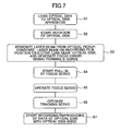
- the flowchart of Fig. 7 shows operations performed with the pull-in process.
- an optical disk is loaded into a disk drive apparatus (Step S1). Then, the loaded optical disk is rotated (Step S2). Then, an optical pickup irradiates an optical beam onto the optical disk and moves an objective lens toward the optical disk for focusing the irradiated beam on a recording surface of the optical disk.
- the detected focus error signal since axial runout in the above-described amount occurs in the optical disk, the detected focus error signal generates a waveform shaped as an S-letter curve (see (a) of Fig.8 ) having the focal point as its center (Step S3). Then, the S-letter curve is monitored for detecting a zero-crossing point. Upon detecting the zero-crossing point, the position of the optical beam is determined, that is, pull-in for a subsequent focus control operation is conducted (Step S4).
- Step S5 a focus control operation is conducted.
- Step S6 a tracking control operation is conducted.
- Step S7 a process of recording/reproducing data is conducted.
- an optical disk recording/reproducing apparatus using a flexible optical disk is disclosed in Japanese Laid-Open Patent Application No. 2006-107698 .
- This optical disk recording/reproducing apparatus is configured to reduce axial runout by using a stabilizing member for applying aerodynamic force to the flexible optical disk.
- a stabilizing member for applying aerodynamic force to the flexible optical disk.
- the maximum amount of axial runout exhibited by the optical disk ranges from 1 ⁇ m p-p to 10 ⁇ m p-p .
- the amount of axial runout exhibited by the optical disk is approximately 1/10 to 1/300 compared to that of the common existing optical disk. Thus, axial runout is significantly reduced with the optical disk recording/reproducing apparatus.
- Japanese Laid-Open Patent Application No. 2002-358759 discloses a method in which focus control is performed after obtaining a predetermined height by adjusting the amount of a stabilizing member projecting with respect to an optical disk and detecting an S-curve of a focus error signal.
- a constantly occurring disturbance can be reduced during a focus control operation after a pull-in process.
- the focus error amount during high speed rotation of an optical disk can be reduced, to thereby enable a suitable focus control operation during the high speed rotation.
- the stabilizing member may contact the optical disk depending on the amount of the projection. Furthermore, an S-curve may not be consistently formed by using this method.
- the present invention may provide a data recording/reproduction method and a data recording/reproduction method that substantially obviates one or more of the problems caused by the limitations and disadvantages of the related art.
- an embodiment of the present invention provides a data recording/reproduction method for performing a data recording/reproduction process on a flexible optical disk by rotating the flexible optical disk while controlling an axial runout of the flexible optical disk with a stabilizing member that applies an aerodynamic force to the flexible optical disk, and irradiating an optical beam and focusing the optical beam to the flexible optical disk, the method including the steps of: a) generating a first axial runout; b) generating a focus error signal forming an S-curve when the first axial runout is generated; c) determining a position of the optical beam according to the focus error signal; d) generating a second axial runout that is smaller than the first axial runout after step c); and e) conducting at least one of the data recording process and the data reproduction process after step d).
- another embodiment of the present invention provides a data recording/reproduction apparatus for performing a data recording/reproduction process on a flexible optical disk by rotating the flexible optical disk while controlling an axial runout of the flexible optical disk with a stabilizing member that applies an aerodynamic force to the flexible optical disk, and irradiating an optical beam and focusing the optical beam to the flexible optical disk
- the apparatus including: a first operation control mode determining part configured to generate a first axial runout; an optical pickup configured to generate a focus error signal forming an S-curve when the first axial runout is generated; a pull-in part configured to determine a position of the optical beam according to the focus error signal; a second operation control mode determining part configured to generate a second axial runout that is smaller than the first axial runout; and a recording/reproducing part configured to conduct at least one of the data recording process and the data reproduction process.
- Fig. 1 is a schematic diagram of a recording/reproducing apparatus 100 according to a first embodiment of the present invention.
- reference numeral 1 indicates an optical disk which is flexible;
- reference numeral 2 indicates a hub for holding the center of rotation of the optical disk 1;
- reference numeral 3 indicates a spindle motor for driving the rotation of the optical disk 1;
- reference numeral 4 indicates an optical pickup for optically scanning the optical disk 1 by irradiating an optical beam L onto a recording surface of the optical disk 1 and focusing the optical beam L to form a beam spot S on the recording surface of the optical disk 1;
- reference numeral 5 indicates an objective lens 5 included in the optical pickup 4 for focusing the irradiated beam L onto the recording surface of the optical disk 1;
- reference numeral 6 indicates a stabilizing member positioned opposite to the recording surface of the optical disk 1 for reducing axial runout of the optical disk 1 by applying an aerodynamic force to the optical disk 1 during rotation (e.g., high speed rotation) of the optical disk 1.
- the stabilizing member 6 may be curved at its sides relative to the tangential line of an accessing (feeding) direction of the optical pickup 4 with respect to the optical disk 1 (see, for example, Japanese Laid-Open Patent Application Nos. 2007-80336 and 2007-149311 ). Furthermore, the center line of the curve of the stabilizing member 6 does not need to match the tangential line of the accessing direction of the optical pickup 4.
- the optical disk 1 may be slightly tilted (e.g., 10 degrees) for reducing axial runout of the optical disk 1.
- reference numeral 7 indicates a recording/reproducing part for performing at least a process of recording data in the optical disk 1 (recording process) or a process of reproducing data recorded in the optical disk 1 (reproduction process).
- the recording/reproducing part 7 may output recording signals indicating data to be recorded in the optical disk 1 to the optical pickup 4 or output reproduction signals according to changes of reflected light from the optical disk 1 detected by the optical pickup 4.
- reference numeral 8 indicates a rotation control part for controlling the rotational speed of the spindle motor 3. In this embodiment of the present invention, the rotation control part 8 controls the rotation of the optical disk 1 to be a constant rotational speed of 15,000 rpm during recording/reproduction of data.
- reference numeral 9 indicates a CPU (Central Processing Unit) for controlling various parts and components included in the recording/reproducing apparatus 100.
- CPU Central Processing Unit
- Reference numeral 10 indicates a focus servo part 10 for adjusting the focus of the objective lens 5 with respect to the optical disk 1.
- Reference numeral 11 indicates a focus servo pull-in part for perform a pull-in process of the focus servo by determining an S-curve formed by a focus error signal detected by the optical pickup 4.
- Reference numeral 12 indicates a first stabilizing member positioning part (first operation control mode determining part) for moving the stabilizing member 6 to a position causing a predetermined axial runout (first operation control mode).
- the predetermined axial runout of the first operation control mode is greater than a permissible axial runout that is obtained when the optical disk 1 is stably rotated having the axial runout reduced (controlled) to substantially a minimum value.
- the first stabilizing member positioning part 12 includes or is connected to a sequencer 14, a motor 15, a pinion gear 16, and a rack gear 17.
- the sequencer 14 is operated according to instructions from the CPU 9.
- the motor 15 is controlled to rotate forward and reverse by the sequencer 14.
- the pinion gear 16 is fixed to a base plate 18 at a predetermined height from the base plate 18.
- the rack gear 17 meshes with the pinion gear 16 and has one end fixed to the stabilizing member 6.
- the rotation of the motor 15 is transmitted to the pinion gear 16 and causes the pinion gear 16 to rotate forward or reverse.
- the rack gear 17 moves upward or downward according to the rotating direction of the pinion gear 16 meshed thereto.
- the movement (translation) of the rack gear 17 raises or lowers the stabilizing member 6.
- the displacement of the stabilizing member 6 is controlled by adjusting the rack gear 17. Accordingly, the stabilizing member 6 can be moved from a position farther from the optical disk 1 to a position at which pull-in of the focus servo (focus servo pull-in position) is conducted.
- Reference numeral 13 indicates a second stabilizing member positioning part 13 (second operation control mode determining part) for moving the stabilizing member 6 to a position in which the axial runout of the optical disk 1 is controlled within the permissible axial runout by applying aerodynamic force to the optical disk 1 (second operation control mode).
- the second stabilizing member positioning part 13 may have, for example, substantially the same configuration as the first stabilizing member positioning part 12 shown in Fig. 9 . That is, the second stabilizing member positioning part 13 includes or is connected to a sequencer 14, a motor 15, a pinion gear 16, and a rack gear 17. Likewise, the sequencer 14 is operated according to instructions from the CPU 9. The motor 15 is controlled to rotate forward and reverse by the sequencer 14.
- the pinion gear 16 is fixed to a base plate 18 at a predetermined height from the base plate 18.
- the rack gear 17 meshes with the pinion gear 16 and has one end fixed to the stabilizing member 6.
- the rotation of the motor 15 is transmitted to the pinion gear 16 and causes the pinion gear 16 to rotate forward or reverse.
- the rack gear 17 moves upward or downward according to the rotating direction of the pinion gear 16 meshed thereto.
- the movement (translation) of the rack gear 17 raises or lowers the stabilizing member 6.
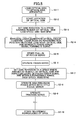
- Fig. 2 is a flowchart showing a pull-in operation of a focus servo according to the first embodiment of the present invention.
- the optical disk 1 is loaded onto the hub 2 of the optical disk apparatus 100 (Step S1-1). Then, the rotation control part 8 rotates the optical disk 1 to a predetermined rotational speed (e.g., 2,000 rpm) (Step S1-2). In step S1-2, the stabilizing member is positioned approximately 10 mm away from the optical disk 1 (standby position). The optical disk 1 is provided at a position for preventing other components (including the stabilizing member 6) from contacting the optical disk 1.
- a predetermined rotational speed e.g., 2,000 rpm
- the first stabilizing member positioning part 12 moves the stabilizing member 6 toward the optical disk 1 (S1-3).
- the gap "Cbd" between the optical disk 1 and the stabilizing member 6 is set to a predetermined value (e.g., 0.3 mm) so that the amount of axial runout of the optical disk 1 ranges from approximately 10 ⁇ m to 100 ⁇ m (maximum of 300 ⁇ m) (first operation control mode).
- Step S1-4 focus error detection is performed by irradiating an optical beam (laser beam) L from the optical pickup 4 and moving the objective lens 5 toward the optical disk 1 (Step S1-4).
- Step S1-4 a S-curve is clearly formed by the focus error signal since the axial runout caused by the optical disk 1 is large.
- the focus servo pull-in part 11 initiates pull-in of the focus servo (S1-5).
- the focus servo part 10 performs a focus servo process on a beam spot S formed on the recording surface of the optical disk 1 (Step S1-6).
- Step S1-6 the axial runout of the optical disk 1 is not yet at a suitable value (not within a permissible range of 0 ⁇ m p-p to 10 ⁇ m p-p . Therefore, in Step S1-7, the second stabilizing member positioning part 13 moves the stabilizing member 6 toward the optical disk 1 in order to control the amount of axial runout of the optical disk 1 or the runout acceleration of the optical disk to be a suitable value and also to control the amplitude level of the focus error signal to a suitable value (minimum value).
- a suitable value minimum value
- the gap "Cbd" between the optical disk 1 and the stabilizing member 6 is set to be a predetermined value (in this example, approximately 0.1 mm) or a predetermined permissible range so that the amount of axial runout of the optical disk 1 becomes a suitable value (in this example, the generated axial runout of the optical disk 1 is 5 ⁇ m) (second operation control mode).
- the second operation control mode With the second operation control mode, the high speed rotation of the optical disk 1 and the operations of the stabilizing member 6 realize a highly precise focus servo with little focus error (Step S1-8).
- Step S1-9 a tracking operation is conducted. Then, when the position of the optical beam L is stably maintained along a desired track on the recording surface of the optical disk 1 by the tracking operation, data are recorded to the optical disk 1 or data recorded in the optical disk 1 are reproduced (Step S1-10).
- the optical disk apparatus 100 in a case of performing focus control on a thin flexible optical disk 1 by using the stabilizing member 6 for effectively reducing axial runout during high speed rotation of the optical disk 1, the pull-in of the focus servo can be reliably executed. Thereby, high speed recording/reproduction of data can be performed with the optical disk apparatus 100.
- Fig. 4 is a schematic diagram showing a recording/reproducing apparatus 200 according to a second embodiment of the present invention. It is to be noted that, in the second embodiment of the present invention, like components of the first embodiment of the present invention are denoted with like reference numerals and are not further explained.
- the recording/reproducing apparatus 200 has no first and second stabilizing member positioning parts 12, 13.
- the gap between the optical disk 1 and the stabilizing member 6 is set (determined) beforehand.
- the rotation control part 8 is set with a predetermined value for enabling the spindle motor 2 to rotate the optical disk 1 at a rotational speed that generates an axial runout greater than the above-described permissible axial runout (first operation control mode).
- the rotation control part 8 is set with another predetermined value for enabling the spindle motor 2 to rotate the optical disk at a rotational speed that generates an axial runout within the above-described permissible range when the focus servo is in focus state (second operation control mode).
- the rotation control part 8 according to the second embodiment of the present invention functions as the first and second operation control mode determining parts.
- the optical disk 1 is loaded onto the hub 2 of the optical disk apparatus 200 (Step S2-1).
- Step S2-1 the optical disk 1 is loaded at a position forming a gap relative to the stabilizing member 6.
- the gap is set to be a predetermined value (in this example, 0.25 mm).
- the rotation control part 8 initiates rotation of the optical disk 1 (Step S2-2).
- Step S2-3 the rotation control part 8 sets the rotation of the optical disk 1 at a rotational speed corresponding to the first operation control mode (in this example, a low rotational speed ranging from 2,000 rpm to 4,000 rpm).
- Step S1-4 an S-curve is clearly formed by the focus error signal since the axial runout generated by the optical disk 1 is large.
- the focus servo pull-in part 11 initiates pull-in of the focus servo (S2-5).
- the focus servo part 10 performs a focus servo operation with respect to a beam spot S of the optical beam L formed on the surface of the optical disk 1 (Step S2-6).
- Step S2-7 the rotation control part 8 sets the rotation of the optical disk 1 at a rotational speed corresponding to the second operation control mode (in this example, a high rotational speed of 15,000 rpm). That is, the optical disk 1 is rotated at a rotational speed in order to control the amount of axial runout of the optical disk 1 or the runout acceleration of the optical disk to be a suitable value and also to control the amplitude level of the focus error signal to be a suitable value (minimum value).
- the second operation control mode the high speed rotation of the optical disk 1 and the aerodynamic effect applied by the stabilizing member 6 realize a highly precise focus servo operation with little focus error (Step S2-8).
- Step S2-9 a tracking operation is conducted. Then, when the position of the optical beam L is stably maintained along a desired track on the surface of the optical disk 1 by the tracking operation, data are recorded to the optical disk 1 or data recorded in the optical disk 1 are reproduced (Step S2-10).
- the optical disk apparatus 200 in a case of performing focus control on a thin flexible optical disk 1 by using the stabilizing member 6 for effectively reducing axial runout during high speed rotation of the optical disk 1, the pull-in of the focus servo can be reliably executed. Thereby, high speed recording/reproduction of data can be performed with the optical disk apparatus 200.
- Fig. 6 is a flowchart showing a pull-in operation of the focus servo according to the third embodiment of the present invention.
- the pull-in operation performed by a recording/reproducing apparatus according to the third embodiment of the present invention basically has the same configuration as the recording/reproducing apparatus 100 shown in Fig. 1 .
- the optical disk 1 is loaded onto the hub 2 of the optical disk apparatus 100 (Step S3-1). Then, the rotation control part 8 rotates the optical disk 1 to attain a predetermined rotational speed (Step S3-2).
- the stabilizing member 6 is positioned approximately 10 mm away from the optical disk 1 (standby position).
- the optical disk 1 is provided at a position for preventing other components (including the stabilizing member 6) from contacting the optical disk 1.
- the first stabilizing member positioning part 12 moves the stabilizing member 6 toward the optical disk 1 and the rotation control part 8 sets the rotation of the optical disk 1 at a rotational speed corresponding to the first operation control mode (a low rotational speed less than the below-described rotational speed corresponding to the second operation control mode) (Step S3-3).
- the gap Cbd between the stabilizing member 6 and the optical disk 1 and the rotational speed corresponding to the first operation control mode are calculated beforehand for generating an axial runout ranging from approximately 10 ⁇ m to 100 ⁇ m.
- Step S3-4 focus error detection is performed by irradiating an optical beam (laser beam) L from the optical pickup 4 and moving the objective lens 5 toward the optical disk 1 (Step S3-4).
- Step S3-4 a S-curve is clearly formed by the focus error signal since the axial runout generated by the optical disk 1 is large.
- the focus servo pull-in part 11 initiates pull-in of the focus servo (S3-5).
- the focus servo part 10 performs a focus servo operation with respect to a beam spot S of the optical beam L formed on the surface of the optical disk 1 (Step S3-6).
- Step S3-6 the axial runout of the optical disk 1 is not yet at a suitable value (not within a permissible range of 0 ⁇ m p-p to 10 ⁇ m p-p . Therefore, in Step S3-7, the second stabilizing member positioning part 13 moves the stabilizing member 6 toward the optical disk 1 (in this example, cbd is set to approximately 0.1 mm) along with having the rotation control part 8 set the rotation of the optical disk 1 at a rotational speed corresponding to the second operation control mode (in this example, a high rotational speed of 15,000 rpm).
- the second stabilizing member positioning part 13 moves the stabilizing member 6 toward the optical disk 1 (in this example, cbd is set to approximately 0.1 mm) along with having the rotation control part 8 set the rotation of the optical disk 1 at a rotational speed corresponding to the second operation control mode (in this example, a high rotational speed of 15,000 rpm).
- Step S3-9 a tracking operation is conducted. Then, when the position of the optical beam L is stably maintained along a desired track on the surface of the optical disk 1 by the tracking operation, data are recorded to the optical disk 1 or data recorded in the optical disk 1 are reproduced (Step S3-10).
- the optical disk apparatus in a case of performing focus control on a thin flexible optical disk 1 by using the stabilizing member 6 for effectively reducing axial runout during high speed rotation of the optical disk 1, the pull-in operation of the focus servo can be reliably executed. Thereby, high speed recording/reproduction of data can be performed with the optical disk apparatus 200.
Landscapes
- Optical Recording Or Reproduction (AREA)
Applications Claiming Priority (2)
| Application Number | Priority Date | Filing Date | Title |
|---|---|---|---|
| JP2007133991 | 2007-05-21 | ||
| JP2008090585A JP4965494B2 (ja) | 2007-05-21 | 2008-03-31 | 記録再生方法および記録再生装置 |
Publications (3)
| Publication Number | Publication Date |
|---|---|
| EP1998327A2 true EP1998327A2 (de) | 2008-12-03 |
| EP1998327A3 EP1998327A3 (de) | 2009-05-27 |
| EP1998327B1 EP1998327B1 (de) | 2010-09-15 |
Family
ID=39731536
Family Applications (1)
| Application Number | Title | Priority Date | Filing Date |
|---|---|---|---|
| EP08251773A Not-in-force EP1998327B1 (de) | 2007-05-21 | 2008-05-21 | Datenaufzeichnungs- bzw. -wiedergabeverfahren, Datenaufzeichungs- bzw. -wiedergabevorrichtung |
Country Status (2)
| Country | Link |
|---|---|
| US (1) | US8259543B2 (de) |
| EP (1) | EP1998327B1 (de) |
Cited By (1)
| Publication number | Priority date | Publication date | Assignee | Title |
|---|---|---|---|---|
| EP2302629A3 (de) * | 2009-09-24 | 2012-07-04 | Ricoh Company, Ltd. | Plattenklemmmechanismus und Plattenlaufwerksystem |
Families Citing this family (3)
| Publication number | Priority date | Publication date | Assignee | Title |
|---|---|---|---|---|
| EP2263231B1 (de) * | 2008-03-13 | 2015-05-06 | Ricoh Company, Ltd. | Flexible und beschreibbare Platte |
| JP5154984B2 (ja) * | 2008-03-14 | 2013-02-27 | 株式会社リコー | 記録/再生装置及び記録/再生方法 |
| US11166878B2 (en) | 2014-01-27 | 2021-11-09 | Hospi Corporation | Method and apparatus for preparing liquid suspensions and solutions from medications in pill or tablet form |
Citations (4)
| Publication number | Priority date | Publication date | Assignee | Title |
|---|---|---|---|---|
| JP2002358759A (ja) | 2001-05-28 | 2002-12-13 | Ricoh Co Ltd | 情報記録再生装置及び情報記録再生装置の粗調整方法 |
| JP2006107698A (ja) | 2004-09-08 | 2006-04-20 | Ricoh Co Ltd | 記録/再生装置およびその駆動方法 |
| JP2007080336A (ja) | 2005-09-13 | 2007-03-29 | Ricoh Co Ltd | ディスク装置及びディスクカートリッジ |
| JP2007149311A (ja) | 2005-09-13 | 2007-06-14 | Ricoh Co Ltd | ディスク装置及びディスクカートリッジ |
Family Cites Families (9)
| Publication number | Priority date | Publication date | Assignee | Title |
|---|---|---|---|---|
| US4672599A (en) | 1980-06-18 | 1987-06-09 | Eastman Kodak Company | Optical disc unit and method and apparatus for writing and/or reading information thereon |
| EP0458477A3 (de) | 1990-05-18 | 1991-12-04 | Imperial Chemical Industries Plc | Stabilisierung von flexiblen optischen Aufzeichnungsmedien |
| JP2001209981A (ja) | 1999-02-09 | 2001-08-03 | Ricoh Co Ltd | 光ディスク基板成膜装置、光ディスク基板成膜方法、基板ホルダーの製造方法、基板ホルダー、光ディスクおよび相変化記録型光ディスク |
| US7233554B2 (en) | 2001-04-17 | 2007-06-19 | Ricoh Company, Ltd. | Disk drive system employing effective disk surface stabilization mechanism |
| US7164629B2 (en) | 2002-01-22 | 2007-01-16 | Ricoh Company, Ltd. | Method of controlling an optical disk apparatus |
| US7194750B2 (en) | 2003-01-28 | 2007-03-20 | Ricoh Company, Ltd. | Recording/reproducing apparatus and disk cartridge |
| US7407698B2 (en) | 2003-05-07 | 2008-08-05 | Ricoh Company, Ltd. | Flexible optical disk |
| US7367036B2 (en) | 2004-09-08 | 2008-04-29 | Ricoh Company, Ltd. | Recording/reproduction apparatus, driving method therefor and disk cartridge |
| JP4650950B2 (ja) | 2006-10-17 | 2011-03-16 | 株式会社リコー | ディスク搬送装置及びディスク装置 |
-
2008
- 2008-05-20 US US12/153,512 patent/US8259543B2/en not_active Expired - Fee Related
- 2008-05-21 EP EP08251773A patent/EP1998327B1/de not_active Not-in-force
Patent Citations (4)
| Publication number | Priority date | Publication date | Assignee | Title |
|---|---|---|---|---|
| JP2002358759A (ja) | 2001-05-28 | 2002-12-13 | Ricoh Co Ltd | 情報記録再生装置及び情報記録再生装置の粗調整方法 |
| JP2006107698A (ja) | 2004-09-08 | 2006-04-20 | Ricoh Co Ltd | 記録/再生装置およびその駆動方法 |
| JP2007080336A (ja) | 2005-09-13 | 2007-03-29 | Ricoh Co Ltd | ディスク装置及びディスクカートリッジ |
| JP2007149311A (ja) | 2005-09-13 | 2007-06-14 | Ricoh Co Ltd | ディスク装置及びディスクカートリッジ |
Cited By (2)
| Publication number | Priority date | Publication date | Assignee | Title |
|---|---|---|---|---|
| EP2302629A3 (de) * | 2009-09-24 | 2012-07-04 | Ricoh Company, Ltd. | Plattenklemmmechanismus und Plattenlaufwerksystem |
| US8549547B2 (en) | 2009-09-24 | 2013-10-01 | Ricoh Company, Ltd. | Disk clamping mechanism and disk drive system, with movably supported clamper |
Also Published As
| Publication number | Publication date |
|---|---|
| US8259543B2 (en) | 2012-09-04 |
| EP1998327A3 (de) | 2009-05-27 |
| EP1998327B1 (de) | 2010-09-15 |
| US20090010123A1 (en) | 2009-01-08 |
Similar Documents
| Publication | Publication Date | Title |
|---|---|---|
| EP1998327B1 (de) | Datenaufzeichnungs- bzw. -wiedergabeverfahren, Datenaufzeichungs- bzw. -wiedergabevorrichtung | |
| US20070274166A1 (en) | Optical disc drive | |
| US20030174599A1 (en) | Optical disk apparatus and method of controlling optical disk apparatus | |
| US8089835B2 (en) | Optical disc apparatus and tracking control method | |
| KR20020042199A (ko) | 광 기록 재생기의 편심 제어 방법 및 장치 | |
| JP4965494B2 (ja) | 記録再生方法および記録再生装置 | |
| US7729221B2 (en) | Optical disk discrimination method and optical disk device | |
| JP3565275B2 (ja) | フォーカスサーチ方法 | |
| JP2010079945A (ja) | 光ディスク記録再生装置および光ディスク記録再生装置の光ピックアップの温度特性補正方法 | |
| US8520480B2 (en) | Optical disc apparatus, method of controlling the same, and information storage medium | |
| JP2008034039A (ja) | 光ディスクドライブ装置及び光ディスクドライブ装置のサーボ制御方法 | |
| JP4167693B2 (ja) | 光ディスク装置およびアクチュエータ制御方法 | |
| JP2004118912A (ja) | 光ディスク装置及びその装置の制御方法 | |
| CN101169946A (zh) | 光盘装置和聚焦控制方法 | |
| CN100405469C (zh) | 相变化型光盘存储控制方法 | |
| JP2001126269A (ja) | 光ディスク装置 | |
| JP4091490B2 (ja) | フォーカスサーボ引き込み装置及びその方法 | |
| JP2005174383A (ja) | 迷光オフセットの除去方法及び光ディスク装置 | |
| US20060198257A1 (en) | Optical disk drive and optical disk drive control method | |
| JP2008204575A (ja) | 光ディスク再生装置 | |
| JP2011150776A (ja) | 光ディスク装置およびデータ記録方法 | |
| JP2006294153A (ja) | フォーカスサーボ装置およびフォーカスサーボ方法 | |
| JP2006309882A (ja) | 光ディスク装置 | |
| JP2006031877A (ja) | 光ディスク記録再生装置のフォーカス制御方法 | |
| JP2005085323A (ja) | 光ディスク装置 |
Legal Events
| Date | Code | Title | Description |
|---|---|---|---|
| PUAI | Public reference made under article 153(3) epc to a published international application that has entered the european phase |
Free format text: ORIGINAL CODE: 0009012 |
|
| 17P | Request for examination filed |
Effective date: 20080603 |
|
| AK | Designated contracting states |
Kind code of ref document: A2 Designated state(s): AT BE BG CH CY CZ DE DK EE ES FI FR GB GR HR HU IE IS IT LI LT LU LV MC MT NL NO PL PT RO SE SI SK TR |
|
| AX | Request for extension of the european patent |
Extension state: AL BA MK RS |
|
| PUAL | Search report despatched |
Free format text: ORIGINAL CODE: 0009013 |
|
| AK | Designated contracting states |
Kind code of ref document: A3 Designated state(s): AT BE BG CH CY CZ DE DK EE ES FI FR GB GR HR HU IE IS IT LI LT LU LV MC MT NL NO PL PT RO SE SI SK TR |
|
| AX | Request for extension of the european patent |
Extension state: AL BA MK RS |
|
| AKX | Designation fees paid |
Designated state(s): DE FR GB NL |
|
| GRAP | Despatch of communication of intention to grant a patent |
Free format text: ORIGINAL CODE: EPIDOSNIGR1 |
|
| RIN1 | Information on inventor provided before grant (corrected) |
Inventor name: TOKUMARU, HARUKIC/O NIPPON HOSO KYOKAI Inventor name: TAKANO, YOSHIMICHI Inventor name: ONAGI, NOBUAKI Inventor name: AMAN, YASUTOMO Inventor name: KOIDE, DAIICHIC/O NIPPON HOSO KYOKAI |
|
| GRAS | Grant fee paid |
Free format text: ORIGINAL CODE: EPIDOSNIGR3 |
|
| GRAA | (expected) grant |
Free format text: ORIGINAL CODE: 0009210 |
|
| RIN1 | Information on inventor provided before grant (corrected) |
Inventor name: TOKUMARU, HARUKI Inventor name: ONAGI, NOBUAKI Inventor name: KOIDE, DAIICHI Inventor name: AMAN, YASUTOMO Inventor name: TAKANO, YOSHIMICHI |
|
| AK | Designated contracting states |
Kind code of ref document: B1 Designated state(s): DE FR GB NL |
|
| REG | Reference to a national code |
Ref country code: GB Ref legal event code: FG4D |
|
| REF | Corresponds to: |
Ref document number: 602008002469 Country of ref document: DE Date of ref document: 20101028 Kind code of ref document: P |
|
| REG | Reference to a national code |
Ref country code: NL Ref legal event code: T3 |
|
| PLBE | No opposition filed within time limit |
Free format text: ORIGINAL CODE: 0009261 |
|
| STAA | Information on the status of an ep patent application or granted ep patent |
Free format text: STATUS: NO OPPOSITION FILED WITHIN TIME LIMIT |
|
| 26N | No opposition filed |
Effective date: 20110616 |
|
| REG | Reference to a national code |
Ref country code: DE Ref legal event code: R097 Ref document number: 602008002469 Country of ref document: DE Effective date: 20110616 |
|
| REG | Reference to a national code |
Ref country code: FR Ref legal event code: PLFP Year of fee payment: 9 |
|
| PGFP | Annual fee paid to national office [announced via postgrant information from national office to epo] |
Ref country code: NL Payment date: 20160519 Year of fee payment: 9 |
|
| PGFP | Annual fee paid to national office [announced via postgrant information from national office to epo] |
Ref country code: DE Payment date: 20160520 Year of fee payment: 9 Ref country code: GB Payment date: 20160520 Year of fee payment: 9 |
|
| PGFP | Annual fee paid to national office [announced via postgrant information from national office to epo] |
Ref country code: FR Payment date: 20160520 Year of fee payment: 9 |
|
| REG | Reference to a national code |
Ref country code: DE Ref legal event code: R119 Ref document number: 602008002469 Country of ref document: DE |
|
| REG | Reference to a national code |
Ref country code: NL Ref legal event code: MM Effective date: 20170601 |
|
| GBPC | Gb: european patent ceased through non-payment of renewal fee |
Effective date: 20170521 |
|
| REG | Reference to a national code |
Ref country code: FR Ref legal event code: ST Effective date: 20180131 |
|
| PG25 | Lapsed in a contracting state [announced via postgrant information from national office to epo] |
Ref country code: NL Free format text: LAPSE BECAUSE OF NON-PAYMENT OF DUE FEES Effective date: 20170601 |
|
| PG25 | Lapsed in a contracting state [announced via postgrant information from national office to epo] |
Ref country code: GB Free format text: LAPSE BECAUSE OF NON-PAYMENT OF DUE FEES Effective date: 20170521 Ref country code: DE Free format text: LAPSE BECAUSE OF NON-PAYMENT OF DUE FEES Effective date: 20171201 |
|
| PG25 | Lapsed in a contracting state [announced via postgrant information from national office to epo] |
Ref country code: FR Free format text: LAPSE BECAUSE OF NON-PAYMENT OF DUE FEES Effective date: 20170531 |