EP1998302A2 - Mesorohr-Verteiler zur Einbrennung - Google Patents
Mesorohr-Verteiler zur Einbrennung Download PDFInfo
- Publication number
- EP1998302A2 EP1998302A2 EP08157006A EP08157006A EP1998302A2 EP 1998302 A2 EP1998302 A2 EP 1998302A2 EP 08157006 A EP08157006 A EP 08157006A EP 08157006 A EP08157006 A EP 08157006A EP 1998302 A2 EP1998302 A2 EP 1998302A2
- Authority
- EP
- European Patent Office
- Prior art keywords
- chamber
- vacuum
- tube
- exterior
- burn
- Prior art date
- Legal status (The legal status is an assumption and is not a legal conclusion. Google has not performed a legal analysis and makes no representation as to the accuracy of the status listed.)
- Granted
Links
- 125000006850 spacer group Chemical group 0.000 claims description 15
- 239000007789 gas Substances 0.000 abstract description 27
- 230000007613 environmental effect Effects 0.000 abstract description 12
- 238000000034 method Methods 0.000 abstract description 9
- 230000008569 process Effects 0.000 abstract description 7
- 238000011109 contamination Methods 0.000 abstract description 4
- 238000007789 sealing Methods 0.000 abstract description 2
- 238000004544 sputter deposition Methods 0.000 description 4
- 230000009977 dual effect Effects 0.000 description 3
- 239000000463 material Substances 0.000 description 3
- 238000010586 diagram Methods 0.000 description 2
- 238000004519 manufacturing process Methods 0.000 description 2
- 229910052754 neon Inorganic materials 0.000 description 2
- GKAOGPIIYCISHV-UHFFFAOYSA-N neon atom Chemical compound [Ne] GKAOGPIIYCISHV-UHFFFAOYSA-N 0.000 description 2
- UFHFLCQGNIYNRP-UHFFFAOYSA-N Hydrogen Chemical compound [H][H] UFHFLCQGNIYNRP-UHFFFAOYSA-N 0.000 description 1
- ZOKXTWBITQBERF-UHFFFAOYSA-N Molybdenum Chemical compound [Mo] ZOKXTWBITQBERF-UHFFFAOYSA-N 0.000 description 1
- 230000015556 catabolic process Effects 0.000 description 1
- 238000001514 detection method Methods 0.000 description 1
- 230000000694 effects Effects 0.000 description 1
- 230000005684 electric field Effects 0.000 description 1
- 238000005530 etching Methods 0.000 description 1
- 238000005247 gettering Methods 0.000 description 1
- 239000001257 hydrogen Substances 0.000 description 1
- 229910052739 hydrogen Inorganic materials 0.000 description 1
- 150000002500 ions Chemical class 0.000 description 1
- 230000004048 modification Effects 0.000 description 1
- 238000012986 modification Methods 0.000 description 1
- 229910052750 molybdenum Inorganic materials 0.000 description 1
- 239000011733 molybdenum Substances 0.000 description 1
- WFKWXMTUELFFGS-UHFFFAOYSA-N tungsten Chemical compound [W] WFKWXMTUELFFGS-UHFFFAOYSA-N 0.000 description 1
- 229910052721 tungsten Inorganic materials 0.000 description 1
- 239000010937 tungsten Substances 0.000 description 1
Images

Classifications
-
- H—ELECTRICITY
- H01—ELECTRIC ELEMENTS
- H01J—ELECTRIC DISCHARGE TUBES OR DISCHARGE LAMPS
- H01J9/00—Apparatus or processes specially adapted for the manufacture, installation, removal, maintenance of electric discharge tubes, discharge lamps, or parts thereof; Recovery of material from discharge tubes or lamps
- H01J9/38—Exhausting, degassing, filling, or cleaning vessels
- H01J9/385—Exhausting vessels
-
- H—ELECTRICITY
- H01—ELECTRIC ELEMENTS
- H01J—ELECTRIC DISCHARGE TUBES OR DISCHARGE LAMPS
- H01J17/00—Gas-filled discharge tubes with solid cathode
- H01J17/38—Cold-cathode tubes
- H01J17/40—Cold-cathode tubes with one cathode and one anode, e.g. glow tubes, tuning-indicator glow tubes, voltage-stabiliser tubes, voltage-indicator tubes
-
- H—ELECTRICITY
- H01—ELECTRIC ELEMENTS
- H01J—ELECTRIC DISCHARGE TUBES OR DISCHARGE LAMPS
- H01J9/00—Apparatus or processes specially adapted for the manufacture, installation, removal, maintenance of electric discharge tubes, discharge lamps, or parts thereof; Recovery of material from discharge tubes or lamps
- H01J9/38—Exhausting, degassing, filling, or cleaning vessels
- H01J9/395—Filling vessels
-
- H—ELECTRICITY
- H01—ELECTRIC ELEMENTS
- H01J—ELECTRIC DISCHARGE TUBES OR DISCHARGE LAMPS
- H01J9/00—Apparatus or processes specially adapted for the manufacture, installation, removal, maintenance of electric discharge tubes, discharge lamps, or parts thereof; Recovery of material from discharge tubes or lamps
- H01J9/44—Factory adjustment of completed discharge tubes or lamps to comply with desired tolerances
- H01J9/445—Aging of tubes or lamps, e.g. by "spot knocking"
Definitions
- Embodiments relate to the manufacture of flame detector tubes and vacuum tubes. Embodiments also relate to sputtering, gettering, vacuum chambers, manifolds, and process gas delivery systems.
- Vacuum tubes the predecessors of transistors and diodes, are air tight chambers with cathodes and anodes.
- the air is largely evacuated from the tube, hence the name vacuum tube.
- the tube's cathode is held at a lower voltage than the tube's anode so that electrons are accelerated from the cathode to the anode.
- electrons move to the anode, they collide with air molecules knocking even more electrons loose and thereby amplifying the number of electrons.
- the cathode is heated to produce thermionic electrons.
- photons are allowed to impact the cathode to cause the release of photoelectrons.
- Vacuum tubes are rarely used in circuitry any more. They are, however, often used in light detection. Some tubes are so sensitive that a single photon can cause an electron to leave the cathode and induce a large avalanche of secondary and tertiary electrons that reach the anode.
- One type of photon sensitive tube is a flame detector tube. A flame detector tube is sensitive to the photons produced by flames.
- a tube's anode and cathode are subjected to a constant and necessary bombardment of electrons and ions. The result is the etching and sputtering of the cathode and anode.
- the anode and cathode are often made from or coated with resistant materials such as tungsten and molybdenum while still being consistent with the demands for the proper work function.
- the gas in the tube is chosen to be one that will not damage the anodes and cathodes too much nor react with other tube materials consistent with proper breakdown characteristics. Neon and a neon/hydrogen mix are often used as tube gasses because they are fairly light and nonreactive.
- Burn-in is a process in which the tube is run at an elevated voltage to sputter the surfaces smooth.
- the materials and gases used in vacuum tubes are specifically chosen to minimize sputtering.
- Engineering decisions for extended tube life also cause long burn-in times.
- a burn-in manifold has a first chamber, a cavity, and a lid.
- the lid covers the cavity to form a second chamber.
- An interior wall is shared by the first chamber and the second chamber.
- the interior wall has an interior wall opening and that the lid has an exterior opening.
- a vacuum tube's fill tube can reach into the first chamber by passing through the exterior opening, through the second chamber and through the interior wall opening.
- An exterior seal can seal the fill tube to the exterior wall to prevent environmental gas from entering the second chamber.
- An interior seal can seal the fill tube to the interior wall to prevent gas from passing from the first chamber into the second chamber.
- O rings can be used as interior seals and as exterior seals.
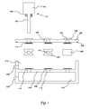
- Fig. 1 illustrates a burn-in manifold with a lid in accordance with aspects of the embodiments
- Fig. 2 illustrates a burn-in manifold with a lid and installed vacuum tubes in accordance with aspects of the embodiments
- Fig. 3 illustrates a burn-in manifold in accordance with aspects of the embodiments
- Fig. 4 illustrates a burn-in manifold lid in accordance with aspects of the embodiments
- Fig. 5 illustrates a burn-in manifold cavity in accordance with aspects of the embodiments
- Fig. 6 illustrates a cut view of a burn-in manifold lid in accordance with aspects of the embodiments.
- Fig. 7 illustrates high level flow diagram of using a burn-in manifold in accordance with aspects of the embodiments.
- a two chamber system with fill gas in one chamber and vacuum in the other provides a means of burning in one or more vacuum tubes while avoiding contamination from environmental gases.
- Vacuum tubes are often burned in after being sealed. Some processes burn-in the tubes before sealing them. The burn in process can take days and provide ample opportunity for environmental gases to contaminate the vacuum tube.
- the vacuum tube's fill tube passes through the vacuum chamber and into the fill gas chamber. Environmental gases leaking past the fill tube are evacuated by the vacuum. Similarly, fill gas leaking past the fill tube is also evacuated to vacuum. As such, the environmental gases are drawn away before contaminating the vacuum tube.
- Fig. 1 illustrates a burn-in manifold with a lid 107 in accordance with aspects of the embodiments.
- the lid 107 has exterior openings 105, burn in connectors 107, exterior seals 104, and a gasket 108.
- the exterior seals can be O-rings that rest in cups 115.
- a manifold body has a cavity 112 and a first chamber 113 separated by an interior wall 116.
- the interior wall has interior wall openings 114 as well as seals 104 and cups 115.
- Spacer rings 109, 110 can press the seals 104 against the interior wall 116 and lid 107.
- a ported spacer ring 110 has ports 111 passing from the spacer ring's center to its exterior.
- a vacuum port 118 can be connected to a vacuum source while a fill port 117 can be connected to a gas source.
- a vacuum tube 119 has a body 101, fill tube 103 and tube connectors 102.
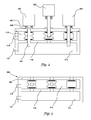
- Fig. 2 illustrates a burn-in manifold with a lid 107 and installed vacuum tubes 201, 202 in accordance with aspects of the embodiments.
- the burn-in manifold of Fig. 2 is the same as that of Fig. 1 with the exception that the lid 107 and spacer rings are installed.
- Vacuum tubes 201 have been pressed through the exterior openings, through the spacer rings, through the interior openings, and into the first chamber.
- a fill gas in the first chamber 113 will pass into the vacuum tubes 201.
- Fill gas leaking through the interior openings will b evacuated out the vacuum port 118 and will not pass into the outside atmosphere.
- environmental gases leaking through the exterior openings will be evacuated to vacuum and will not enter the first chamber 113. This is particularly important because otherwise a single bad seal could contaminate every vacuum tube.
- the vacuum tubes 201 have their tube connectors 102 mated to the lids burn-in connectors. As such, the tubes can be burned in.
- One vacuum tube 202 is illustrated as pressed into a ported spacer ring.
- the fill tube is exposed to vacuum such that environmental gas is evacuated from the vacuum tube and out the vacuum port 118.
- the interior seals and exterior seals minimize the leakage of gases, but can not be trusted to completely prevent all leakage for the entire time that the vacuum tubes burn-in.
- a burn-in manifold designed for a single tube at a time benefits from the dual chamber arrangement because otherwise it would depend on a single seal and no vacuum evacuation.
- the dual chamber arrangement is particularly advantageous for a multiple tube manifold such as those illustrated. The reason is a single chamber manifold system contaminates all the vacuum tubes when a single seal fails. Furthermore, single seal failures can easily occur during an entire burn in cycle.
- the dual chamber arrangement is resistant to contamination because it is designed to work properly in spite of less than perfect seals.
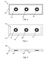
- Fig. 3 illustrates a burn-in manifold 300 in accordance with aspects of the embodiments.
- the burn-in manifold of Fig. 3 is the same as that of Fig. 2 with the exception of having no lid.
- the burn-in manifold 300 has a permanent exterior wall 301.
- the exterior wall 301 has exterior openings, seals, and cups.
- Fig. 4 illustrates a burn-in manifold lid 107 in accordance with aspects of the embodiments.
- the lid 107 has a gasket 108, exterior openings 105, seals 104, cups 115, and gasket 108.
- Fig. 5 illustrates a burn-in manifold cavity in accordance with aspects of the embodiments.
- the cavity 112 is surrounded by cavity walls 501 with the interior wall 116 forming the cavity 112 bottom.
- the interior wall 116 has interior openings 114, seals 104, cups 115, and gasket 108.
- Fig. 6 illustrates a cut view of a lid 600 with recessed cups 601 in accordance with aspects of the embodiments.
- the lid 600 has exterior openings 105, a gasket 108, and seals 104.
- a recessed cup 601 can hold a seal 104 such as on O ring and can be less expensive to produce.
- Fig. 7 illustrates high level flow diagram of using a burn-in manifold in accordance with aspects of the embodiments.
- a burn-in manifold is obtained 702 and vacuum tubes are obtained 703.
- the vacuum tubes' fill tubes are pressed through the manifolds exterior openings such that they reach into the spacer rings but not into the interior openings 705.
- the second chamber is evacuated 705 which also evacuates the vacuum tubes.
- the fill tubes are then pressed through the interior openings such that the tube connectors and burn-in connectors mate 706.
- Fill gas is passed into the first chamber such that the vacuum tubes are filled 707 and then the vacuum tubes are burned in 708.
- the burn in process is done 709 and the vacuum tubes can be sealed and packaged for sale.
Landscapes
- Engineering & Computer Science (AREA)
- Manufacturing & Machinery (AREA)
- Manufacture Of Electron Tubes, Discharge Lamp Vessels, Lead-In Wires, And The Like (AREA)
- Measurement Of Radiation (AREA)
- Sampling And Sample Adjustment (AREA)
- Examining Or Testing Airtightness (AREA)
Applications Claiming Priority (1)
| Application Number | Priority Date | Filing Date | Title |
|---|---|---|---|
| US11/807,561 US7918706B2 (en) | 2007-05-29 | 2007-05-29 | Mesotube burn-in manifold |
Publications (3)
| Publication Number | Publication Date |
|---|---|
| EP1998302A2 true EP1998302A2 (de) | 2008-12-03 |
| EP1998302A3 EP1998302A3 (de) | 2011-01-26 |
| EP1998302B1 EP1998302B1 (de) | 2012-11-21 |
Family
ID=39769225
Family Applications (1)
| Application Number | Title | Priority Date | Filing Date |
|---|---|---|---|
| EP08157006A Ceased EP1998302B1 (de) | 2007-05-29 | 2008-05-27 | Mesorohr-Verteiler zur Einbrennung |
Country Status (4)
| Country | Link |
|---|---|
| US (1) | US7918706B2 (de) |
| EP (1) | EP1998302B1 (de) |
| JP (1) | JP2009021219A (de) |
| CN (1) | CN101320668A (de) |
Families Citing this family (4)
| Publication number | Priority date | Publication date | Assignee | Title |
|---|---|---|---|---|
| US7893615B2 (en) * | 2007-09-18 | 2011-02-22 | Honeywell International, Inc. | Ultra violet flame sensor with run-on detection |
| US7750284B2 (en) * | 2008-07-25 | 2010-07-06 | Honeywell International Inc. | Mesotube with header insulator |
| CN104538223A (zh) * | 2015-01-04 | 2015-04-22 | 沈阳华德海泰电子有限公司 | 一种自清洁式真空开关管高压老炼系统 |
| US10549214B2 (en) | 2017-03-10 | 2020-02-04 | Savannah River Nuclear Solutions, Llc | Device for residue handling minimization with vacuum-assisted separations |
Citations (2)
| Publication number | Priority date | Publication date | Assignee | Title |
|---|---|---|---|---|
| EP1193031A1 (de) | 2000-09-29 | 2002-04-03 | Infineon Technologies SC300 GmbH & Co. KG | Vorrichtung zum Polieren von Scheibenartigen Gegenständen |
| US20030019812A1 (en) | 2000-06-26 | 2003-01-30 | Berger Terry A. | Exhaust gas collection system for supercritical fluid chromatography |
Family Cites Families (17)
| Publication number | Priority date | Publication date | Assignee | Title |
|---|---|---|---|---|
| US3966287A (en) * | 1975-06-27 | 1976-06-29 | Rca Corporation | Low-voltage aging of cathode-ray tubes |
| US4665740A (en) * | 1984-08-22 | 1987-05-19 | Nippondenso Co., Ltd. | Combustion process sensor |
| JPH0668947B2 (ja) * | 1990-01-08 | 1994-08-31 | 浜松ホトニクス株式会社 | 光電面の形成方法 |
| US5443416A (en) * | 1993-09-09 | 1995-08-22 | Cybeq Systems Incorporated | Rotary union for coupling fluids in a wafer polishing apparatus |
| US5763888A (en) * | 1995-01-30 | 1998-06-09 | Ametek Aerospace Products, Inc. | High temperature gas stream optical flame sensor and method for fabricating same |
| JPH09270085A (ja) * | 1996-04-01 | 1997-10-14 | Hamamatsu Photonics Kk | 発煙検知装置 |
| US5941699A (en) * | 1997-05-08 | 1999-08-24 | Mr. Heater, Inc. | Shutoff system for gas fired appliances |
| US6784430B2 (en) | 1999-02-08 | 2004-08-31 | General Electric Company | Interdigitated flame sensor, system and method |
| KR100491913B1 (ko) * | 1999-03-31 | 2005-05-27 | 가부시끼가이샤 도시바 | 평판형 화상 표시 장치의 제조 방법 및 평판형 화상 표시장치 |
| US6171513B1 (en) * | 1999-04-30 | 2001-01-09 | International Business Machines Corporation | Chemical-mechanical polishing system having a bi-material wafer backing film and two-piece wafer carrier |
| US6344414B1 (en) * | 1999-04-30 | 2002-02-05 | International Business Machines Corporation | Chemical-mechanical polishing system having a bi-material wafer backing film assembly |
| US6780378B2 (en) * | 2001-06-28 | 2004-08-24 | Gas Technology Institute | Method for measuring concentrations of gases and vapors using controlled flames |
| US6784460B2 (en) * | 2002-10-10 | 2004-08-31 | Agilent Technologies, Inc. | Chip shaping for flip-chip light emitting diode |
| WO2005111556A2 (en) * | 2004-05-07 | 2005-11-24 | Walter Kidde Portable Equipment, Inc. | Flame detector with uv sensor |
| US7202794B2 (en) * | 2004-07-20 | 2007-04-10 | General Monitors, Inc. | Flame detection system |
| JP2007165478A (ja) * | 2005-12-12 | 2007-06-28 | National Univ Corp Shizuoka Univ | 光電面及び光検出器 |
| US7456412B2 (en) * | 2007-04-11 | 2008-11-25 | Honeywell International Inc. | Insulator for tube having conductive case |
-
2007
- 2007-05-29 US US11/807,561 patent/US7918706B2/en not_active Expired - Fee Related
-
2008
- 2008-05-27 EP EP08157006A patent/EP1998302B1/de not_active Ceased
- 2008-05-28 JP JP2008139621A patent/JP2009021219A/ja not_active Withdrawn
- 2008-05-28 CN CNA2008101428726A patent/CN101320668A/zh active Pending
Patent Citations (2)
| Publication number | Priority date | Publication date | Assignee | Title |
|---|---|---|---|---|
| US20030019812A1 (en) | 2000-06-26 | 2003-01-30 | Berger Terry A. | Exhaust gas collection system for supercritical fluid chromatography |
| EP1193031A1 (de) | 2000-09-29 | 2002-04-03 | Infineon Technologies SC300 GmbH & Co. KG | Vorrichtung zum Polieren von Scheibenartigen Gegenständen |
Also Published As
| Publication number | Publication date |
|---|---|
| CN101320668A (zh) | 2008-12-10 |
| US7918706B2 (en) | 2011-04-05 |
| JP2009021219A (ja) | 2009-01-29 |
| EP1998302A3 (de) | 2011-01-26 |
| EP1998302B1 (de) | 2012-11-21 |
| US20080298934A1 (en) | 2008-12-04 |
Similar Documents
| Publication | Publication Date | Title |
|---|---|---|
| JP5719174B2 (ja) | 小型映像増倍管およびそのような増倍管が取り付けられる暗視システム | |
| US8018234B2 (en) | Electron source for a vacuum pressure measuring device | |
| US7918706B2 (en) | Mesotube burn-in manifold | |
| CN107636791B (zh) | 电子显微镜用样品室装置及具备其的电子显微镜 | |
| TWI719122B (zh) | 改良式離子源陰極遮罩及包含改良式離子源陰極遮罩之電弧箱與離子源 | |
| CN104198131B (zh) | 行波管检漏设备在行波管检漏中的应用方法 | |
| CN108885960A (zh) | 改进的离子源推斥极护罩 | |
| JP7530545B2 (ja) | 走査型電子顕微鏡用電子銃チャンバー、これを含む電子銃及び走査電子顕微鏡 | |
| US7871303B2 (en) | System for filling and venting of run-in gas into vacuum tubes | |
| JP6198305B2 (ja) | 荷電粒子線装置 | |
| US20240085374A1 (en) | Partial pressure gauge assembly for process contaminant detection using photoionization and associated method | |
| JP5530917B2 (ja) | 試料ホルダの排気方法及び装置 | |
| US8410442B2 (en) | Detector tube stack with integrated electron scrub system and method of manufacturing the same | |
| JP2008115445A (ja) | ターゲットホルダ及び成膜装置並びに成膜方法 | |
| KR0183548B1 (ko) | 전계 방출 표시장치 | |
| JPH11162397A (ja) | イオンビーム照射装置 | |
| JP2013127849A (ja) | X線管 | |
| KR19990065843A (ko) | Fed제조 공정중 진공 페키징 방법 및 그에 따른 패널 구조 | |
| US6930446B1 (en) | Method for improving current stability of field emission displays | |
| JPS61163534A (ja) | 画像表示装置の脱ガス処理方法 | |
| CN119361397A (zh) | X射线装置以及x射线球管的维护方法 | |
| KR0160007B1 (ko) | 전계 방출 표시장치 | |
| Li et al. | A novel differentially pumped UHV flange in the CESR interaction region | |
| WO2018142179A1 (en) | Apparatus for applying a deposition onto a substrate by a deposition process and method for carrying out a deposition process by use of such an apparatus | |
| JP2009070701A (ja) | 表示パネルの製造装置及びガス導入装置 |
Legal Events
| Date | Code | Title | Description |
|---|---|---|---|
| PUAI | Public reference made under article 153(3) epc to a published international application that has entered the european phase |
Free format text: ORIGINAL CODE: 0009012 |
|
| 17P | Request for examination filed |
Effective date: 20080527 |
|
| AK | Designated contracting states |
Kind code of ref document: A2 Designated state(s): AT BE BG CH CY CZ DE DK EE ES FI FR GB GR HR HU IE IS IT LI LT LU LV MC MT NL NO PL PT RO SE SI SK TR |
|
| AX | Request for extension of the european patent |
Extension state: AL BA MK RS |
|
| PUAL | Search report despatched |
Free format text: ORIGINAL CODE: 0009013 |
|
| AK | Designated contracting states |
Kind code of ref document: A3 Designated state(s): AT BE BG CH CY CZ DE DK EE ES FI FR GB GR HR HU IE IS IT LI LT LU LV MC MT NL NO PL PT RO SE SI SK TR |
|
| AX | Request for extension of the european patent |
Extension state: AL BA MK RS |
|
| 17Q | First examination report despatched |
Effective date: 20110117 |
|
| AKX | Designation fees paid |
Designated state(s): DE FR GB |
|
| GRAP | Despatch of communication of intention to grant a patent |
Free format text: ORIGINAL CODE: EPIDOSNIGR1 |
|
| GRAS | Grant fee paid |
Free format text: ORIGINAL CODE: EPIDOSNIGR3 |
|
| GRAA | (expected) grant |
Free format text: ORIGINAL CODE: 0009210 |
|
| AK | Designated contracting states |
Kind code of ref document: B1 Designated state(s): DE FR GB |
|
| REG | Reference to a national code |
Ref country code: GB Ref legal event code: FG4D |
|
| REG | Reference to a national code |
Ref country code: DE Ref legal event code: R096 Ref document number: 602008020200 Country of ref document: DE Effective date: 20130117 |
|
| PLBE | No opposition filed within time limit |
Free format text: ORIGINAL CODE: 0009261 |
|
| STAA | Information on the status of an ep patent application or granted ep patent |
Free format text: STATUS: NO OPPOSITION FILED WITHIN TIME LIMIT |
|
| 26N | No opposition filed |
Effective date: 20130822 |
|
| REG | Reference to a national code |
Ref country code: DE Ref legal event code: R097 Ref document number: 602008020200 Country of ref document: DE Effective date: 20130822 |
|
| REG | Reference to a national code |
Ref country code: FR Ref legal event code: PLFP Year of fee payment: 9 |
|
| REG | Reference to a national code |
Ref country code: FR Ref legal event code: PLFP Year of fee payment: 10 |
|
| REG | Reference to a national code |
Ref country code: FR Ref legal event code: PLFP Year of fee payment: 11 |
|
| PGFP | Annual fee paid to national office [announced via postgrant information from national office to epo] |
Ref country code: FR Payment date: 20180525 Year of fee payment: 11 |
|
| PGFP | Annual fee paid to national office [announced via postgrant information from national office to epo] |
Ref country code: DE Payment date: 20180731 Year of fee payment: 11 Ref country code: GB Payment date: 20180530 Year of fee payment: 11 |
|
| REG | Reference to a national code |
Ref country code: DE Ref legal event code: R119 Ref document number: 602008020200 Country of ref document: DE |
|
| GBPC | Gb: european patent ceased through non-payment of renewal fee |
Effective date: 20190527 |
|
| PG25 | Lapsed in a contracting state [announced via postgrant information from national office to epo] |
Ref country code: DE Free format text: LAPSE BECAUSE OF NON-PAYMENT OF DUE FEES Effective date: 20191203 Ref country code: GB Free format text: LAPSE BECAUSE OF NON-PAYMENT OF DUE FEES Effective date: 20190527 |
|
| PG25 | Lapsed in a contracting state [announced via postgrant information from national office to epo] |
Ref country code: FR Free format text: LAPSE BECAUSE OF NON-PAYMENT OF DUE FEES Effective date: 20190531 |