EP1998148A2 - Vorrichtung zur Berechnung eines absoluten Winkels - Google Patents
Vorrichtung zur Berechnung eines absoluten Winkels Download PDFInfo
- Publication number
- EP1998148A2 EP1998148A2 EP08075519A EP08075519A EP1998148A2 EP 1998148 A2 EP1998148 A2 EP 1998148A2 EP 08075519 A EP08075519 A EP 08075519A EP 08075519 A EP08075519 A EP 08075519A EP 1998148 A2 EP1998148 A2 EP 1998148A2
- Authority
- EP
- European Patent Office
- Prior art keywords
- photoelectrically
- converted signal
- circuit
- angular position
- absolute
- Prior art date
- Legal status (The legal status is an assumption and is not a legal conclusion. Google has not performed a legal analysis and makes no representation as to the accuracy of the status listed.)
- Granted
Links
Images





Classifications
-
- G—PHYSICS
- G01—MEASURING; TESTING
- G01D—MEASURING NOT SPECIALLY ADAPTED FOR A SPECIFIC VARIABLE; ARRANGEMENTS FOR MEASURING TWO OR MORE VARIABLES NOT COVERED IN A SINGLE OTHER SUBCLASS; TARIFF METERING APPARATUS; MEASURING OR TESTING NOT OTHERWISE PROVIDED FOR
- G01D5/00—Mechanical means for transferring the output of a sensing member; Means for converting the output of a sensing member to another variable where the form or nature of the sensing member does not constrain the means for converting; Transducers not specially adapted for a specific variable
- G01D5/26—Mechanical means for transferring the output of a sensing member; Means for converting the output of a sensing member to another variable where the form or nature of the sensing member does not constrain the means for converting; Transducers not specially adapted for a specific variable characterised by optical transfer means, i.e. using infrared, visible, or ultraviolet light
- G01D5/32—Mechanical means for transferring the output of a sensing member; Means for converting the output of a sensing member to another variable where the form or nature of the sensing member does not constrain the means for converting; Transducers not specially adapted for a specific variable characterised by optical transfer means, i.e. using infrared, visible, or ultraviolet light with attenuation or whole or partial obturation of beams of light
- G01D5/34—Mechanical means for transferring the output of a sensing member; Means for converting the output of a sensing member to another variable where the form or nature of the sensing member does not constrain the means for converting; Transducers not specially adapted for a specific variable characterised by optical transfer means, i.e. using infrared, visible, or ultraviolet light with attenuation or whole or partial obturation of beams of light the beams of light being detected by photocells
- G01D5/347—Mechanical means for transferring the output of a sensing member; Means for converting the output of a sensing member to another variable where the form or nature of the sensing member does not constrain the means for converting; Transducers not specially adapted for a specific variable characterised by optical transfer means, i.e. using infrared, visible, or ultraviolet light with attenuation or whole or partial obturation of beams of light the beams of light being detected by photocells using displacement encoding scales
- G01D5/3473—Circular or rotary encoders
-
- G—PHYSICS
- G01—MEASURING; TESTING
- G01D—MEASURING NOT SPECIALLY ADAPTED FOR A SPECIFIC VARIABLE; ARRANGEMENTS FOR MEASURING TWO OR MORE VARIABLES NOT COVERED IN A SINGLE OTHER SUBCLASS; TARIFF METERING APPARATUS; MEASURING OR TESTING NOT OTHERWISE PROVIDED FOR
- G01D5/00—Mechanical means for transferring the output of a sensing member; Means for converting the output of a sensing member to another variable where the form or nature of the sensing member does not constrain the means for converting; Transducers not specially adapted for a specific variable
- G01D5/12—Mechanical means for transferring the output of a sensing member; Means for converting the output of a sensing member to another variable where the form or nature of the sensing member does not constrain the means for converting; Transducers not specially adapted for a specific variable using electric or magnetic means
- G01D5/244—Mechanical means for transferring the output of a sensing member; Means for converting the output of a sensing member to another variable where the form or nature of the sensing member does not constrain the means for converting; Transducers not specially adapted for a specific variable using electric or magnetic means influencing characteristics of pulses or pulse trains; generating pulses or pulse trains
- G01D5/24409—Interpolation using memories
Definitions
- the present invention relates to an absolute angle calculation apparatus which calculates an absolute angular position with respect to a reference angular position with a rotary encoder incorporated, for example, in a rotary laser apparatus or the like.
- one of known surveying instruments such as a rotary laser apparatus 1 is configured to detect an absolute angular position ⁇ of a target 2 with respect to a reference angular position Q of the rotary laser apparatus 1 by rotating a rotating prism (not illustrated), for example, at three revolutions per second (180 rpm), projecting a fan beam BP onto the target 2, and receiving a reflected light beam BP' from the target 2.
- a rotating prism not illustrated
- the rotary laser apparatus 1 subsequently projects a laser beam to the target 2, for example, at the detected absolute angular position ⁇ , and receives the reflected light beam BP' from the target 2 to measure a distance between the rotary laser apparatus 1 and target 2.
- the rotary laser apparatus 1 of this type internally includes a rotary encoder 3 illustrated in FIGs. 2A and 2B .
- the rotary encoder 3 mainly comprises a rotating plate 4, a light emitting unit 5, and a light receiving unit 6.
- a large number of transmissive slits 7 are formed in a circumferential direction in a peripheral part of the rotating plate 4.
- the large number of transmissive slits 7 include, for example, first to third patterns P 1 to P3 which are spatially modulated as illustrated in FIG 2C .
- Japanese Patent No. 3168451 discloses that the patterns P1 to P3 are formed at a constant pitch width P.
- a pattern width of the pattern 1 is fixed, while the widths of the patterns P2 and P3 are modulated according to a predetermined rule.
- the light emitting unit 5 and light receiving unit 6 are arranged to face a slit-formed region of the rotary plate 4 and to face each other with the rotary plate 4 interposed therebetween.
- the light emitting unit 5 is comprised of, for example, a light emitting element 5a and a collimator lens 5b
- the light receiving unit 6 is comprised of, for example, a linear sensor.
- the light receiving unit 6 receives a light beam from the light emitting unit 5 through the transmissive slits 7 and converts the light beam to a photoelectrically-converted signal string. Then, the photoelectrically-converted signal string is inputted to a calculation circuit (not illustrated).
- the calculation circuit calculates the absolute angular position ⁇ with respect to the reference angular position Q on the basis of a spatially modulated component contained in the photoelectrically-converted signal string in the light receiving unit 6.
- the rotary encoder 3 of this type rotates, for example, about 108° (degrees) for 100 ms. Accordingly, there is a possibility that when a measurement is performed every 100 ms, the absolute angular position ⁇ of the target 2 with respect to the reference angular position Q may not be precisely calculated.
- An object of the present invention is to provide an absolute angle calculation apparatus which is capable of reducing an angle calculation time and in addition precisely measuring the absolute angular position.
- An absolute angle calculation apparatus comprises: a rotary plate having patterns spatially modulated; a light emitting unit facing a rotary range of the patterns; a light receiving unit which receives a light beam obtained from the light emitting unit through the patterns and converts the light beam to photoelectrically-converted signal strings; and a calculation circuit which calculates an absolute angular position with respect to a reference angular position on the basis of a spatially modulated component contained in the photoelectrically-converted signal string outputted from the light receiving unit, the calculation circuit includes: a photoelectrically-converted signal string storage which stores previous and current photoelectrically-converted signal strings outputted, for a purpose of interpolating the absolute angular position, from the light receiving unit at previous and current measurements within a set time shorter than an absolute angle calculation time required for a calculation of the absolute angular position; a correlation detection circuit which detects a correlation between the previous and current photoelectrically-converted signal strings stored in the photoelectrically-converted signal string storage to detect a shift
- the calculation circuit binarizes the photoelectrically-converted signal strings by using a threshold value to detect the shift amount.
- the patterns include transmissive slits, and the light emitting and receiving units face each other with the rotary range of the transmissive slits interposed therebetween.
- the absolute angle calculation apparatus further comprises an amplifier circuit provided between the light receiving unit and the photoelectrically-converted signal string storage, and which amplifies the photoelectrically-converted signal strings.
- the photoelectrically-converted signal string storage comprises: a first storage circuit and a second storage circuit; and wherein the first storage circuit stores a photoelectrically-converted signal string which is obtained at the previous measurement, and the previous measurement is defined as a measurement at a set time just before current time, and the second storage circuit stores a photoelectrically-converted signal string which is obtained at the current measurement, and the current measurement is defined as a measurement at the current time.
- the absolute angle calculation apparatus further comprises a first switching device provided between the amplifier circuit and the photoelectrically-converted signal string storage, and which alternately switches a connection in regard to the amplifier circuit between the first storage circuit and the second storage circuit per predetermined time.
- a first switching device provided between the amplifier circuit and the photoelectrically-converted signal string storage, and which alternately switches a connection in regard to the amplifier circuit between the first storage circuit and the second storage circuit per predetermined time.
- the calculation circuit comprises a microcomputer, and a second switching device is provided between the microcomputer and the photoelectrically-converted signal string storage, and the second switching device, when the amplifier circuit and one of the first storage circuit and the second storage circuit are connected by the first switching device, connects the other of the first storage circuit and the second storage circuit to the microcomputer, and connects one of the first storage circuit and the second storage circuit to the microcomputer, when the amplifier circuit and the other of the first storage circuit and the second storage circuit are connected by the first switching device.
- the light emitting unit comprises a light emitting element and a collimator lens
- the light receiving unit comprises a linear sensor or a CCD (Charge-Coupled Device).
- the correlation detection circuit detects the shift amount by a correlation detection, by using a plurality of elements existing in a center part of all elements which comprise the linear sensor or the CCD, with an element in a center of the all elements being regarded as the center.
- the patterns comprise a plurality of patterns, a pitch width between each pattern is a fixed width, and widths of the patterns are modulated by a predetermined rule, and the interpolation calculation circuit calculates the absolute angular position equivalent value based on the pitch width between each pattern and the shift amount.
- FIG 3 is a block circuit diagram illustrating a configuration of a main portion of the absolute angle calculation apparatus according to the embodiment of the present invention.
- the configuration of a rotary encoder 3 is the same as that illustrated in FIG 1 , and a detailed description thereof is not illustrated.
- reference numeral 10 denotes a linear sensor or a CCD comprising, for example, a large number of light receiving elements as a light receiving unit 6, and reference numeral 11 denotes a calculation circuit.
- the calculation circuit 11 mainly includes a microcomputer 12, a clock driver 13, a photoelectrically-converted signal string storage 14, a correlation detection circuit 15A, and an interpolation calculation circuit 15B.
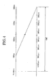
- the microcomputer 12 has a function of setting a set time t shorter than an absolute angle calculation time T taken for calculation illustrated in FIG. 4 for purposes of interpolation of the absolute angular position ⁇ obtained by calculation.
- the absolute angle calculation time T is 100 milliseconds (ms), which corresponds to 108° (degrees) in angle.
- the set time t is 500 microseconds ( ⁇ s), which corresponds to 0.54° in angle.
- the microcomputer 12 outputs a control signal to the clock driver 13, and the clock driver 13 outputs a drive signal to the linear sensor 10.
- the liner sensor 10 outputs a photoelectrically-converted signal string via an amplifier circuit 16 to the photoelectrically-converted signal string storage 14 on the basis of the drive signal from the clock driver 13.
- the number of elements of the linear sensor 10 is 512, for example.
- a pitch width of one element is about 73 seconds in angle, and the angle of the linear sensor 10 is therefore 73 ⁇ 512 seconds, about 10.4°.
- the photoelectrically-converted signal string storage 14 has a function of temporarily storing the photoelectrically-converted signal string outputted from each element of the linear sensor 10 during the set time t set by the microcomputer 12, including storage circuits 14A and 14B.
- One of the storage circuits 14A and 14B functions as a previous string storage circuit storing the photoelectrically-converted signal string obtained at a previous measurement.
- a measurement at the set time t just before current time is defined as the previous measurement
- a measurement at the current time is defined as a current measurement.
- the other one of the storage circuits 14A and 14B functions as a current string storage circuit storing the photoelectrically-converted signal string obtained at the current measurement.
- the microcomputer 12 has a function of controlling switching devices 17 and 18.
- the switching device 17 switches every 500 ⁇ s between a state where the amplifier circuit 16 is connected to the storage circuit 14A and a state where the amplifier circuit 16 is connected to the storage circuit 14B.
- the switching device 18 switches every 500 ⁇ s between a state where the microcomputer 12 is connected to the storage circuit 14A and a state where the microcomputer 12 is connected to the storage circuit 14B. In a state where the switching device 18 connects the storage 14A and microcomputer 12, the switching device 17 is switched to connect the amplifier circuit 16 and storage circuit 14B. In a state where the switching device 18 connects the storage 14B and microcomputer 12, the switching device 17 is switched to connect the amplifier circuit 16 and storage circuit 14A.
- the switching device 18 is used to input the photoelectrically-converted signal string, which is necessary for absolute angle calculation, to the microcomputer 12 every 100 ms.
- Each of the storage circuits 14A and 14B has a function of temporarily storing the photoelectrically-converted signal string outputted from the 512 elements just before a time point of 500 ⁇ s as a reference.
- the microcomputer 12 is connected every 100 ms to the storage circuit 14A or 14B and calculates every absolute angle calculation time T the absolute angular position ⁇ with respect to the reference angular position Q on the basis of a spatially modulated component in the 512 photoelectrically-converted signal strings stored in the storage circuit 14A or 14B.
- the microcomputer 12 outputs a result of a calculation to a display unit 19, and the display unit 19 displays the absolute angular position ⁇ with respect to the reference angular position Q on a screen thereof.
- the microcomputer 12 outputs a control timing signal ST and then the photoelectrically-converted signal strings stored in the storage circuits 14A and 14B are outputted to the correlation detection circuit 15A by the control timing signal ST.
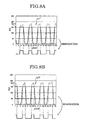
- the correlation detection circuit 15A compares each of 512 photoelectrically-converted signal strings tr1 stored in the storage circuit 14A (see FIG. 5A ) and each photoelectrically-converted signal string tr2 stored in the storage circuit 14B (see FIG. 5B ) according to the correlation method and detects a shift amount ⁇ .
- a photoelectrically-converted signal indicated by x1 in FIG 5A corresponds to a photoelectrically-converted signal indicated by x2 in FIG. 5B and is illustrated as shifted from x2 by eight elements (pixels). Accordingly, the shift amount ⁇ is 8 here.
- the shift amount ⁇ is inputted to the microcomputer 12.
- An interpolated value obtained by the interpolation calculation circuit 15B is also inputted to the microcomputer 12.
- the interpolation calculation circuit 15B calculates an interpolated value (an absolute angle equivalent value) described below on the basis of the photoelectrically-converted signal string outputted from the amplifier circuit 16.
- FIG 6 is a schematic explanatory view of patterns for calculation of the interpolated value.
- FIG 6 illustrates patterns crossing a center of the light receiving element 10 in the rotating direction from a time point when an absolute angle calculation value is calculated to a time point when a next absolute angle calculation value is calculated.
- each of pitch intervals P between each pattern is equal to 14 pixels, for example.
- the interpolation calculation circuit 15B calculates an interpolated value every 0.1 or 1 sec.
- an interpolated value A is equivalent to a value: (8/14) x 1029 seconds.
- a numeric value (number of the pixels) of the shift amount ⁇ is represented by reference symbol M
- a numeric value (number of the pitches) of the M ⁇ 73 seconds divided by 1029 is represented by reference symbol M'
- reference symbol M" is a reminder thereof.
- This incorporated value A is inputted to the microcomputer 12.
- the microcomputer 12 calculates an interpolated angle ⁇ on the basis of the interpolated value A.
- the microcomputer 12 adds the interpolated angle ⁇ obtained at the current measurement to the absolute angular position ⁇ obtained at the previous measurement to calculate a current absolute angular position ( ⁇ + ⁇ ).
- the shift amount ⁇ is 8
- the interpolated angle ⁇ is 588.8 seconds.
- the interpolated value A is calculated on the scale of 0.1 seconds.
- step S. 1 While the rotary encoder 3 is rotating, the microcomputer 12 executes an absolute calculation (absolute angular position calculation) every 100 ms, for example (this time can be arbitrarily set) (step S.1). The microcomputer 12 then clears the count value (step S. 2) and starts to count (step S. 3). Subsequently, the microcomputer 12 divides the count value by, for example, 500 ⁇ s (this time can be arbitrarily set) (step S. 4) and judges whether a quotient N is an integer (step S. 5).
- step S. 5 when the quotient N is judged to be an integer, the microcomputer 12 outputs a switching signal to the switching device 17.
- the switching device 17 is switched from a state where the amplifier circuit 16 is connected to the storage circuit 14A to a state where the amplifier circuit 16 is connected to the storage circuit 14B (step S. 6).
- the switching device 18 is switched to the storage circuit different from the storage circuit connected to the switching device 17.
- the 512 photoelectrically-converted signals tr1 used in the absolute calculation are stored in the storage circuit 14A as a previous photoelectrically-converted signal string tr1.
- the storage circuit 14B stores a current photoclcctrically-converted signal string tr2 (step S. 7).
- Data of the previous photoelectrically-converted signal string tr1 and data of the current photoelectrically-converted signal string tr2 are inputted to the correlation detection circuit 15A, and the correlation detection circuit 15A detects the shift amount ⁇ by the correlation calculation on the basis of the photoelectrically-converted signal strings tr1 and tr2 (step S. 8).
- the shift amount ⁇ is then inputted to the microcomputer 12.
- step S. 10 judges whether N is 200 (step S. 10).
- the state where the amplifier circuit 16 is connected to the storage circuit 14B is switched to the state where the amplifier circuit 16 is connected to the storage circuit 14A, thereby.
- the storage circuit 14B serves as a storage of data of the previous photoelectrically-converted signal string tr1
- the storage circuit 14A serves as a storage of data of the current photoelectrically-converted signal string tr2.
- the data of the previous photoelectrically-converted signal string tr1 stored in the storage circuit 14B and data of the current photoelectrically-converted signal string tr2 stored in the storage circuit 14A are similarly inputted to the correlation detection circuit 15A, and the correlation detection circuit 15A detects the shift amount ⁇ by the correlation calculation based on these data.
- the shift amount ⁇ is inputted to the microcomputer 12.
- the storage circuit 14A serves as a storage of data of the current photoelectrically-converted signal string
- the storage circuit 14B serves as a storage of data of the previous photoelectrically-converted signal string.
- the storage circuit 14A serves as a storage of data of the previous photoelectrically-converted signal string
- the storage circuit 14B serves as a storage of data of the current photoelectrically-converted signal string.
- the microcomputer 12 Every 100 ms, the microcomputer 12 repeatedly calculates the absolute angular position ⁇ with respect to the reference angular position Q on the basis of the spatially modulated component in the photoelectrically-converted signal string stored in the storage circuit 14A or 14B.
- step S. 11 judges whether the rotary encoder 3 is switched off.
- the microcomputer 12 proceeds to step S. 1 and continues processes of steps S. 1 to S.11.
- the absolute angular position ⁇ with respect to the reference angular position Q when receiving the reflected light beam BP' from the target 2 is precisely obtained. Accordingly, when measuring a distance, it is obtained at what angle the rotary laser apparatus 1 should project a distance measuring laser beam with respect to the reference angular position Q. The distance to the target 2 is obtained even when the rotary laser apparatus 1 is unattended.
- the absolute angular position is obtained by interpolation of an absolute angular position using the 512 photoelectrically-converted signals obtained from the 512 elements.
- the interpolation of the absolute angular position by the correlation detection method may be performed using two 32 elements each starting in a different direction from a 256th element at the center of the 512 elements, that is, using 64 elements.
- the correlation detection circuit 15A performs the correlation detection using the photoelectrically-converted signal strings tr1 and tr2, which are raw.
- the shift amount ⁇ may be detected on the basis of photoelectrically-converted signal strings tr1' and tr2' which are obtained by binarizing 64 photoelectrically-converted signals using a threshold Qr.
- the absolute angle calculation apparatus attempts to reduce an angle calculation time and have an effect that makes it possible to precisely measure an absolute anglular position.
- the shift amount is detected by a correlation detection, by using a plurality of elements existing in a center part of all elements which comprise the light receiving unit, with an element in a center of the all elements being regarded as the center, so that a reduction of an operating time is achieved.
Landscapes
- Physics & Mathematics (AREA)
- General Physics & Mathematics (AREA)
- Optical Transform (AREA)
- Transmission And Conversion Of Sensor Element Output (AREA)
Applications Claiming Priority (1)
| Application Number | Priority Date | Filing Date | Title |
|---|---|---|---|
| JP2007140223A JP4989313B2 (ja) | 2007-05-28 | 2007-05-28 | 絶対角度演算装置 |
Publications (3)
| Publication Number | Publication Date |
|---|---|
| EP1998148A2 true EP1998148A2 (de) | 2008-12-03 |
| EP1998148A3 EP1998148A3 (de) | 2010-09-15 |
| EP1998148B1 EP1998148B1 (de) | 2017-12-27 |
Family
ID=39666189
Family Applications (1)
| Application Number | Title | Priority Date | Filing Date |
|---|---|---|---|
| EP08075519.2A Active EP1998148B1 (de) | 2007-05-28 | 2008-05-26 | Vorrichtung zur berechnung eines absoluten winkels |
Country Status (4)
| Country | Link |
|---|---|
| US (1) | US7636644B2 (de) |
| EP (1) | EP1998148B1 (de) |
| JP (1) | JP4989313B2 (de) |
| CN (1) | CN101315289B (de) |
Families Citing this family (1)
| Publication number | Priority date | Publication date | Assignee | Title |
|---|---|---|---|---|
| US8843948B2 (en) * | 2008-09-19 | 2014-09-23 | The Nielsen Company (Us), Llc | Methods and apparatus to detect carrying of a portable audience measurement device |
Citations (1)
| Publication number | Priority date | Publication date | Assignee | Title |
|---|---|---|---|---|
| JP3168451B2 (ja) | 1995-09-24 | 2001-05-21 | 株式会社トプコン | ロータリーエンコーダ |
Family Cites Families (8)
| Publication number | Priority date | Publication date | Assignee | Title |
|---|---|---|---|---|
| US4786891A (en) * | 1986-04-08 | 1988-11-22 | Yokogawa Electric Corporation | Absolute encoder for linear or angular position measurements |
| JP2501227B2 (ja) * | 1988-05-30 | 1996-05-29 | ファナック株式会社 | 絶対位置エンコ―ダ |
| EP0414953B1 (de) * | 1989-09-01 | 1993-07-07 | Kabushiki Kaisha S.G. | Positionswertgeber |
| JP2003185472A (ja) * | 2001-12-21 | 2003-07-03 | Yaskawa Electric Corp | アブソリュートエンコーダおよびその絶対値信号生成処理方法 |
| JP2006029933A (ja) * | 2004-07-15 | 2006-02-02 | Neive:Kk | 画像式スケール |
| CN100359290C (zh) * | 2004-09-08 | 2008-01-02 | 中国科学院长春光学精密机械与物理研究所 | 一种提高光电编码器测角精度的方法 |
| JP4846331B2 (ja) * | 2005-01-18 | 2011-12-28 | 株式会社ミツトヨ | 光電式エンコーダ、及び、そのスケール |
| EP1890113A1 (de) * | 2006-08-18 | 2008-02-20 | Leica Geosystems AG | Optoelektronischer winkelsensor und verfahren zum bestimmen eines drehwinkels um eine achse |
-
2007
- 2007-05-28 JP JP2007140223A patent/JP4989313B2/ja not_active Expired - Fee Related
-
2008
- 2008-05-26 EP EP08075519.2A patent/EP1998148B1/de active Active
- 2008-05-27 CN CN2008100977552A patent/CN101315289B/zh not_active Expired - Fee Related
- 2008-05-27 US US12/127,609 patent/US7636644B2/en active Active
Patent Citations (1)
| Publication number | Priority date | Publication date | Assignee | Title |
|---|---|---|---|---|
| JP3168451B2 (ja) | 1995-09-24 | 2001-05-21 | 株式会社トプコン | ロータリーエンコーダ |
Also Published As
| Publication number | Publication date |
|---|---|
| CN101315289B (zh) | 2010-12-01 |
| US7636644B2 (en) | 2009-12-22 |
| CN101315289A (zh) | 2008-12-03 |
| EP1998148A3 (de) | 2010-09-15 |
| JP2008292389A (ja) | 2008-12-04 |
| US20080300822A1 (en) | 2008-12-04 |
| EP1998148B1 (de) | 2017-12-27 |
| JP4989313B2 (ja) | 2012-08-01 |
Similar Documents
| Publication | Publication Date | Title |
|---|---|---|
| KR960010541B1 (ko) | 테이프자 장치 | |
| US9068821B2 (en) | Optical measuring device with positional displacement detection | |
| US7805277B2 (en) | Step number measuring apparatus | |
| CN101319898A (zh) | 测量系统 | |
| WO2010101207A1 (ja) | 電子ペンシステム、ずれ測定装置、表示方法、及びプログラム | |
| EP1998148B1 (de) | Vorrichtung zur berechnung eines absoluten winkels | |
| EP2407835B1 (de) | Funkuhr | |
| EP2312273B1 (de) | Verschiebungsdetektor, Verschiebungsdetektionsverfahren und Computerprogrammprodukt | |
| KR101005781B1 (ko) | 각도 측정 장치 및 방법 | |
| JP4833503B2 (ja) | 厚さ測定装置 | |
| JP3708270B2 (ja) | 電子レベル | |
| US8011112B2 (en) | Method and apparatus for determining positions | |
| JP2006245685A (ja) | 光電センサ | |
| JP4858707B2 (ja) | 変位検出装置 | |
| JP4468128B2 (ja) | アブソリュートエンコーダ、及び、その信号処理方法 | |
| US7091884B2 (en) | Analog position encoder | |
| KR100721614B1 (ko) | 복수의 센서를 이용하여 계측 범위를 확장시킨 계측장치 및계측방법 | |
| JPH10221077A (ja) | 電子レベル | |
| JP4876489B2 (ja) | 断線検出装置 | |
| EP1742021B1 (de) | Ein Lesekopf für ein optisches Messgerät. | |
| JP2006329783A (ja) | インクリメンタルエンコーダ | |
| KR100671963B1 (ko) | 조향각 검출장치 | |
| JP2012154856A (ja) | 周波数計測装置及び周波数位相差比較装置 | |
| JPH07270187A (ja) | 光学的変位量測定方法及び光学的変位量測定装置 | |
| JP3076668B2 (ja) | 測定装置 |
Legal Events
| Date | Code | Title | Description |
|---|---|---|---|
| PUAI | Public reference made under article 153(3) epc to a published international application that has entered the european phase |
Free format text: ORIGINAL CODE: 0009012 |
|
| AK | Designated contracting states |
Kind code of ref document: A2 Designated state(s): AT BE BG CH CY CZ DE DK EE ES FI FR GB GR HR HU IE IS IT LI LT LU LV MC MT NL NO PL PT RO SE SI SK TR |
|
| AX | Request for extension of the european patent |
Extension state: AL BA MK RS |
|
| PUAL | Search report despatched |
Free format text: ORIGINAL CODE: 0009013 |
|
| AK | Designated contracting states |
Kind code of ref document: A3 Designated state(s): AT BE BG CH CY CZ DE DK EE ES FI FR GB GR HR HU IE IS IT LI LT LU LV MC MT NL NO PL PT RO SE SI SK TR |
|
| AX | Request for extension of the european patent |
Extension state: AL BA MK RS |
|
| 17P | Request for examination filed |
Effective date: 20110311 |
|
| AKX | Designation fees paid |
Designated state(s): AT BE BG CH CY CZ DE DK EE ES FI FR GB GR HR HU IE IS IT LI LT LU LV MC MT NL NO PL PT RO SE SI SK TR |
|
| GRAP | Despatch of communication of intention to grant a patent |
Free format text: ORIGINAL CODE: EPIDOSNIGR1 |
|
| INTG | Intention to grant announced |
Effective date: 20170717 |
|
| GRAS | Grant fee paid |
Free format text: ORIGINAL CODE: EPIDOSNIGR3 |
|
| GRAA | (expected) grant |
Free format text: ORIGINAL CODE: 0009210 |
|
| AK | Designated contracting states |
Kind code of ref document: B1 Designated state(s): AT BE BG CH CY CZ DE DK EE ES FI FR GB GR HR HU IE IS IT LI LT LU LV MC MT NL NO PL PT RO SE SI SK TR |
|
| REG | Reference to a national code |
Ref country code: GB Ref legal event code: FG4D |
|
| REG | Reference to a national code |
Ref country code: CH Ref legal event code: EP |
|
| REG | Reference to a national code |
Ref country code: AT Ref legal event code: REF Ref document number: 958689 Country of ref document: AT Kind code of ref document: T Effective date: 20180115 |
|
| REG | Reference to a national code |
Ref country code: IE Ref legal event code: FG4D |
|
| REG | Reference to a national code |
Ref country code: DE Ref legal event code: R096 Ref document number: 602008053479 Country of ref document: DE |
|
| PG25 | Lapsed in a contracting state [announced via postgrant information from national office to epo] |
Ref country code: FI Free format text: LAPSE BECAUSE OF FAILURE TO SUBMIT A TRANSLATION OF THE DESCRIPTION OR TO PAY THE FEE WITHIN THE PRESCRIBED TIME-LIMIT Effective date: 20171227 Ref country code: LT Free format text: LAPSE BECAUSE OF FAILURE TO SUBMIT A TRANSLATION OF THE DESCRIPTION OR TO PAY THE FEE WITHIN THE PRESCRIBED TIME-LIMIT Effective date: 20171227 Ref country code: NO Free format text: LAPSE BECAUSE OF FAILURE TO SUBMIT A TRANSLATION OF THE DESCRIPTION OR TO PAY THE FEE WITHIN THE PRESCRIBED TIME-LIMIT Effective date: 20180327 |
|
| REG | Reference to a national code |
Ref country code: NL Ref legal event code: MP Effective date: 20171227 |
|
| REG | Reference to a national code |
Ref country code: LT Ref legal event code: MG4D |
|
| REG | Reference to a national code |
Ref country code: AT Ref legal event code: MK05 Ref document number: 958689 Country of ref document: AT Kind code of ref document: T Effective date: 20171227 |
|
| PG25 | Lapsed in a contracting state [announced via postgrant information from national office to epo] |
Ref country code: GR Free format text: LAPSE BECAUSE OF FAILURE TO SUBMIT A TRANSLATION OF THE DESCRIPTION OR TO PAY THE FEE WITHIN THE PRESCRIBED TIME-LIMIT Effective date: 20180328 Ref country code: LV Free format text: LAPSE BECAUSE OF FAILURE TO SUBMIT A TRANSLATION OF THE DESCRIPTION OR TO PAY THE FEE WITHIN THE PRESCRIBED TIME-LIMIT Effective date: 20171227 Ref country code: BG Free format text: LAPSE BECAUSE OF FAILURE TO SUBMIT A TRANSLATION OF THE DESCRIPTION OR TO PAY THE FEE WITHIN THE PRESCRIBED TIME-LIMIT Effective date: 20180327 Ref country code: HR Free format text: LAPSE BECAUSE OF FAILURE TO SUBMIT A TRANSLATION OF THE DESCRIPTION OR TO PAY THE FEE WITHIN THE PRESCRIBED TIME-LIMIT Effective date: 20171227 |
|
| PG25 | Lapsed in a contracting state [announced via postgrant information from national office to epo] |
Ref country code: NL Free format text: LAPSE BECAUSE OF FAILURE TO SUBMIT A TRANSLATION OF THE DESCRIPTION OR TO PAY THE FEE WITHIN THE PRESCRIBED TIME-LIMIT Effective date: 20171227 |
|
| PG25 | Lapsed in a contracting state [announced via postgrant information from national office to epo] |
Ref country code: CZ Free format text: LAPSE BECAUSE OF FAILURE TO SUBMIT A TRANSLATION OF THE DESCRIPTION OR TO PAY THE FEE WITHIN THE PRESCRIBED TIME-LIMIT Effective date: 20171227 Ref country code: SK Free format text: LAPSE BECAUSE OF FAILURE TO SUBMIT A TRANSLATION OF THE DESCRIPTION OR TO PAY THE FEE WITHIN THE PRESCRIBED TIME-LIMIT Effective date: 20171227 Ref country code: ES Free format text: LAPSE BECAUSE OF FAILURE TO SUBMIT A TRANSLATION OF THE DESCRIPTION OR TO PAY THE FEE WITHIN THE PRESCRIBED TIME-LIMIT Effective date: 20171227 Ref country code: CY Free format text: LAPSE BECAUSE OF FAILURE TO SUBMIT A TRANSLATION OF THE DESCRIPTION OR TO PAY THE FEE WITHIN THE PRESCRIBED TIME-LIMIT Effective date: 20171227 Ref country code: EE Free format text: LAPSE BECAUSE OF FAILURE TO SUBMIT A TRANSLATION OF THE DESCRIPTION OR TO PAY THE FEE WITHIN THE PRESCRIBED TIME-LIMIT Effective date: 20171227 |
|
| PG25 | Lapsed in a contracting state [announced via postgrant information from national office to epo] |
Ref country code: RO Free format text: LAPSE BECAUSE OF FAILURE TO SUBMIT A TRANSLATION OF THE DESCRIPTION OR TO PAY THE FEE WITHIN THE PRESCRIBED TIME-LIMIT Effective date: 20171227 Ref country code: IT Free format text: LAPSE BECAUSE OF FAILURE TO SUBMIT A TRANSLATION OF THE DESCRIPTION OR TO PAY THE FEE WITHIN THE PRESCRIBED TIME-LIMIT Effective date: 20171227 Ref country code: IS Free format text: LAPSE BECAUSE OF FAILURE TO SUBMIT A TRANSLATION OF THE DESCRIPTION OR TO PAY THE FEE WITHIN THE PRESCRIBED TIME-LIMIT Effective date: 20180427 Ref country code: PL Free format text: LAPSE BECAUSE OF FAILURE TO SUBMIT A TRANSLATION OF THE DESCRIPTION OR TO PAY THE FEE WITHIN THE PRESCRIBED TIME-LIMIT Effective date: 20171227 Ref country code: AT Free format text: LAPSE BECAUSE OF FAILURE TO SUBMIT A TRANSLATION OF THE DESCRIPTION OR TO PAY THE FEE WITHIN THE PRESCRIBED TIME-LIMIT Effective date: 20171227 |
|
| REG | Reference to a national code |
Ref country code: DE Ref legal event code: R097 Ref document number: 602008053479 Country of ref document: DE |
|
| PLBE | No opposition filed within time limit |
Free format text: ORIGINAL CODE: 0009261 |
|
| STAA | Information on the status of an ep patent application or granted ep patent |
Free format text: STATUS: NO OPPOSITION FILED WITHIN TIME LIMIT |
|
| PG25 | Lapsed in a contracting state [announced via postgrant information from national office to epo] |
Ref country code: DK Free format text: LAPSE BECAUSE OF FAILURE TO SUBMIT A TRANSLATION OF THE DESCRIPTION OR TO PAY THE FEE WITHIN THE PRESCRIBED TIME-LIMIT Effective date: 20171227 |
|
| 26N | No opposition filed |
Effective date: 20180928 |
|
| GBPC | Gb: european patent ceased through non-payment of renewal fee |
Effective date: 20180526 |
|
| REG | Reference to a national code |
Ref country code: BE Ref legal event code: MM Effective date: 20180531 |
|
| PG25 | Lapsed in a contracting state [announced via postgrant information from national office to epo] |
Ref country code: MC Free format text: LAPSE BECAUSE OF FAILURE TO SUBMIT A TRANSLATION OF THE DESCRIPTION OR TO PAY THE FEE WITHIN THE PRESCRIBED TIME-LIMIT Effective date: 20171227 |
|
| REG | Reference to a national code |
Ref country code: IE Ref legal event code: MM4A |
|
| PG25 | Lapsed in a contracting state [announced via postgrant information from national office to epo] |
Ref country code: SI Free format text: LAPSE BECAUSE OF FAILURE TO SUBMIT A TRANSLATION OF THE DESCRIPTION OR TO PAY THE FEE WITHIN THE PRESCRIBED TIME-LIMIT Effective date: 20171227 |
|
| PG25 | Lapsed in a contracting state [announced via postgrant information from national office to epo] |
Ref country code: LU Free format text: LAPSE BECAUSE OF NON-PAYMENT OF DUE FEES Effective date: 20180526 |
|
| PG25 | Lapsed in a contracting state [announced via postgrant information from national office to epo] |
Ref country code: FR Free format text: LAPSE BECAUSE OF NON-PAYMENT OF DUE FEES Effective date: 20180531 Ref country code: IE Free format text: LAPSE BECAUSE OF NON-PAYMENT OF DUE FEES Effective date: 20180526 Ref country code: GB Free format text: LAPSE BECAUSE OF NON-PAYMENT OF DUE FEES Effective date: 20180526 |
|
| PG25 | Lapsed in a contracting state [announced via postgrant information from national office to epo] |
Ref country code: BE Free format text: LAPSE BECAUSE OF NON-PAYMENT OF DUE FEES Effective date: 20180531 |
|
| PG25 | Lapsed in a contracting state [announced via postgrant information from national office to epo] |
Ref country code: MT Free format text: LAPSE BECAUSE OF NON-PAYMENT OF DUE FEES Effective date: 20180526 |
|
| PG25 | Lapsed in a contracting state [announced via postgrant information from national office to epo] |
Ref country code: TR Free format text: LAPSE BECAUSE OF FAILURE TO SUBMIT A TRANSLATION OF THE DESCRIPTION OR TO PAY THE FEE WITHIN THE PRESCRIBED TIME-LIMIT Effective date: 20171227 |
|
| PG25 | Lapsed in a contracting state [announced via postgrant information from national office to epo] |
Ref country code: HU Free format text: LAPSE BECAUSE OF FAILURE TO SUBMIT A TRANSLATION OF THE DESCRIPTION OR TO PAY THE FEE WITHIN THE PRESCRIBED TIME-LIMIT; INVALID AB INITIO Effective date: 20080526 Ref country code: PT Free format text: LAPSE BECAUSE OF FAILURE TO SUBMIT A TRANSLATION OF THE DESCRIPTION OR TO PAY THE FEE WITHIN THE PRESCRIBED TIME-LIMIT Effective date: 20171227 |
|
| PG25 | Lapsed in a contracting state [announced via postgrant information from national office to epo] |
Ref country code: SE Free format text: LAPSE BECAUSE OF FAILURE TO SUBMIT A TRANSLATION OF THE DESCRIPTION OR TO PAY THE FEE WITHIN THE PRESCRIBED TIME-LIMIT Effective date: 20171227 |
|
| PGFP | Annual fee paid to national office [announced via postgrant information from national office to epo] |
Ref country code: DE Payment date: 20240328 Year of fee payment: 17 |
|
| PGFP | Annual fee paid to national office [announced via postgrant information from national office to epo] |
Ref country code: CH Payment date: 20240602 Year of fee payment: 17 |
|
| REG | Reference to a national code |
Ref country code: DE Ref legal event code: R119 Ref document number: 602008053479 Country of ref document: DE |
|
| REG | Reference to a national code |
Ref country code: CH Ref legal event code: H13 Free format text: ST27 STATUS EVENT CODE: U-0-0-H10-H13 (AS PROVIDED BY THE NATIONAL OFFICE) Effective date: 20251223 |
|
| PG25 | Lapsed in a contracting state [announced via postgrant information from national office to epo] |
Ref country code: CH Free format text: LAPSE BECAUSE OF NON-PAYMENT OF DUE FEES Effective date: 20250531 |
|
| PG25 | Lapsed in a contracting state [announced via postgrant information from national office to epo] |
Ref country code: DE Free format text: LAPSE BECAUSE OF NON-PAYMENT OF DUE FEES Effective date: 20251202 |