EP1998014A2 - Procédé destiné au fonctionnement d'une turbine à vapeur multiple - Google Patents
Procédé destiné au fonctionnement d'une turbine à vapeur multiple Download PDFInfo
- Publication number
- EP1998014A2 EP1998014A2 EP07003922A EP07003922A EP1998014A2 EP 1998014 A2 EP1998014 A2 EP 1998014A2 EP 07003922 A EP07003922 A EP 07003922A EP 07003922 A EP07003922 A EP 07003922A EP 1998014 A2 EP1998014 A2 EP 1998014A2
- Authority
- EP
- European Patent Office
- Prior art keywords
- cooling medium
- steam
- power plant
- supply
- stage
- Prior art date
- Legal status (The legal status is an assumption and is not a legal conclusion. Google has not performed a legal analysis and makes no representation as to the accuracy of the status listed.)
- Withdrawn
Links
Images

Classifications
-
- F—MECHANICAL ENGINEERING; LIGHTING; HEATING; WEAPONS; BLASTING
- F01—MACHINES OR ENGINES IN GENERAL; ENGINE PLANTS IN GENERAL; STEAM ENGINES
- F01K—STEAM ENGINE PLANTS; STEAM ACCUMULATORS; ENGINE PLANTS NOT OTHERWISE PROVIDED FOR; ENGINES USING SPECIAL WORKING FLUIDS OR CYCLES
- F01K13/00—General layout or general methods of operation of complete plants
- F01K13/02—Controlling, e.g. stopping or starting
-
- F—MECHANICAL ENGINEERING; LIGHTING; HEATING; WEAPONS; BLASTING
- F01—MACHINES OR ENGINES IN GENERAL; ENGINE PLANTS IN GENERAL; STEAM ENGINES
- F01D—NON-POSITIVE DISPLACEMENT MACHINES OR ENGINES, e.g. STEAM TURBINES
- F01D5/00—Blades; Blade-carrying members; Heating, heat-insulating, cooling or antivibration means on the blades or the members
- F01D5/12—Blades
- F01D5/28—Selecting particular materials; Particular measures relating thereto; Measures against erosion or corrosion
-
- F—MECHANICAL ENGINEERING; LIGHTING; HEATING; WEAPONS; BLASTING
- F01—MACHINES OR ENGINES IN GENERAL; ENGINE PLANTS IN GENERAL; STEAM ENGINES
- F01D—NON-POSITIVE DISPLACEMENT MACHINES OR ENGINES, e.g. STEAM TURBINES
- F01D25/00—Component parts, details, or accessories, not provided for in, or of interest apart from, other groups
- F01D25/08—Cooling; Heating; Heat-insulation
- F01D25/12—Cooling
-
- F—MECHANICAL ENGINEERING; LIGHTING; HEATING; WEAPONS; BLASTING
- F01—MACHINES OR ENGINES IN GENERAL; ENGINE PLANTS IN GENERAL; STEAM ENGINES
- F01D—NON-POSITIVE DISPLACEMENT MACHINES OR ENGINES, e.g. STEAM TURBINES
- F01D25/00—Component parts, details, or accessories, not provided for in, or of interest apart from, other groups
- F01D25/08—Cooling; Heating; Heat-insulation
- F01D25/14—Casings modified therefor
-
- F—MECHANICAL ENGINEERING; LIGHTING; HEATING; WEAPONS; BLASTING
- F01—MACHINES OR ENGINES IN GENERAL; ENGINE PLANTS IN GENERAL; STEAM ENGINES
- F01D—NON-POSITIVE DISPLACEMENT MACHINES OR ENGINES, e.g. STEAM TURBINES
- F01D25/00—Component parts, details, or accessories, not provided for in, or of interest apart from, other groups
- F01D25/24—Casings; Casing parts, e.g. diaphragms, casing fastenings
- F01D25/26—Double casings; Measures against temperature strain in casings
-
- F—MECHANICAL ENGINEERING; LIGHTING; HEATING; WEAPONS; BLASTING
- F01—MACHINES OR ENGINES IN GENERAL; ENGINE PLANTS IN GENERAL; STEAM ENGINES
- F01K—STEAM ENGINE PLANTS; STEAM ACCUMULATORS; ENGINE PLANTS NOT OTHERWISE PROVIDED FOR; ENGINES USING SPECIAL WORKING FLUIDS OR CYCLES
- F01K13/00—General layout or general methods of operation of complete plants
- F01K13/006—Auxiliaries or details not otherwise provided for
-
- F—MECHANICAL ENGINEERING; LIGHTING; HEATING; WEAPONS; BLASTING
- F01—MACHINES OR ENGINES IN GENERAL; ENGINE PLANTS IN GENERAL; STEAM ENGINES
- F01K—STEAM ENGINE PLANTS; STEAM ACCUMULATORS; ENGINE PLANTS NOT OTHERWISE PROVIDED FOR; ENGINES USING SPECIAL WORKING FLUIDS OR CYCLES
- F01K13/00—General layout or general methods of operation of complete plants
- F01K13/02—Controlling, e.g. stopping or starting
- F01K13/025—Cooling the interior by injection during idling or stand-by
-
- F—MECHANICAL ENGINEERING; LIGHTING; HEATING; WEAPONS; BLASTING
- F01—MACHINES OR ENGINES IN GENERAL; ENGINE PLANTS IN GENERAL; STEAM ENGINES
- F01K—STEAM ENGINE PLANTS; STEAM ACCUMULATORS; ENGINE PLANTS NOT OTHERWISE PROVIDED FOR; ENGINES USING SPECIAL WORKING FLUIDS OR CYCLES
- F01K7/00—Steam engine plants characterised by the use of specific types of engine; Plants or engines characterised by their use of special steam systems, cycles or processes; Control means specially adapted for such systems, cycles or processes; Use of withdrawn or exhaust steam for feed-water heating
- F01K7/16—Steam engine plants characterised by the use of specific types of engine; Plants or engines characterised by their use of special steam systems, cycles or processes; Control means specially adapted for such systems, cycles or processes; Use of withdrawn or exhaust steam for feed-water heating the engines being only of turbine type
-
- F—MECHANICAL ENGINEERING; LIGHTING; HEATING; WEAPONS; BLASTING
- F05—INDEXING SCHEMES RELATING TO ENGINES OR PUMPS IN VARIOUS SUBCLASSES OF CLASSES F01-F04
- F05D—INDEXING SCHEME FOR ASPECTS RELATING TO NON-POSITIVE-DISPLACEMENT MACHINES OR ENGINES, GAS-TURBINES OR JET-PROPULSION PLANTS
- F05D2220/00—Application
- F05D2220/30—Application in turbines
- F05D2220/31—Application in turbines in steam turbines
-
- F—MECHANICAL ENGINEERING; LIGHTING; HEATING; WEAPONS; BLASTING
- F05—INDEXING SCHEMES RELATING TO ENGINES OR PUMPS IN VARIOUS SUBCLASSES OF CLASSES F01-F04
- F05D—INDEXING SCHEME FOR ASPECTS RELATING TO NON-POSITIVE-DISPLACEMENT MACHINES OR ENGINES, GAS-TURBINES OR JET-PROPULSION PLANTS
- F05D2260/00—Function
- F05D2260/20—Heat transfer, e.g. cooling
- F05D2260/232—Heat transfer, e.g. cooling characterized by the cooling medium
Definitions
- the invention relates to a method for operating a multi-stage steam turbine and a steam power plant, comprising a multi-stage steam turbine, a boiler and a cooling medium supply.
- the rotor could be designed as a welded construction, a nickel-based alloy being used in the live steam region and a conventional material being used in the exhaust steam region.
- a manufactured high-pressure turbine part would be in operation withstand occurring loads.
- the steam temperatures in the exhaust-steam region of the high-pressure turbine during an idling operation or low-load operation are comparatively high, as a result of which the conventional material is thermally stressed too much. This problem occurs in particular during a hot start, since the steam temperatures can not be lowered arbitrarily in order to limit the thermal load of the inflow.
- the invention begins, whose object is to provide a method for operating a steam turbine and a steam power plant, wherein the steam turbine can be produced inexpensively.
- the object directed to the method is achieved by a method for operating a multi-stage steam turbine, the steam turbine being supplied with live steam and after an intermediate stage with a cooling medium.
- the invention is based on the aspect that a high-pressure turbine section in the exhaust steam region can be made of a conventional material if the exhaust steam zone is suitably cooled in idle or light load operation.
- the invention is carried out in which after the intermediate stage in the steam turbine, a cooling medium is supplied.
- the area of the steam turbine is cooled after this intermediate stage.
- the existing before this intermediate section of the steam turbine can be made of a nickel-based alloy, wherein the material used in the Abdampf Jardin can be made of a conventional material, since the temperatures in the exhaust steam can now be selectively lowered.
- the cooling medium is formed from a mixture of motive steam and water.
- the motive steam is removed from the boiler.
- the boiler which is also referred to as a steam generator, can be easily converted to receive motive steam.
- the motive steam can be diverted via a bypass line from the live steam supply. This would be in addition to the branch directly from the boiler another simple and inexpensive way to provide a suitable motive steam that can be used by the addition of water as the cooling medium in the steam turbine.
- the cooling medium is supplied in idle mode or in low load operation.
- the cooling medium is supplied in particular at the beginning of a hot start.
- the temperature of the materials of the high-pressure turbine part is comparatively high, so that when a hot start of the live steam, the entire high-pressure turbine section thermally loaded.
- the high-pressure turbine part during a hot start particularly thermally stressed.
- the cooling medium is supplied during a starting operation until a synchronization and / or a minimum power is reached.
- This has the advantage that the high-pressure steam temperature can be kept constant by controlling the cooling medium mass flow.
- the steam turbine is developed in such a way that after a second stage, an additional cooling medium is additionally supplied.
- the additional cooling medium is in this case preferably diverted from the cooling medium, which is a cost-effective way to convert an existing power plant.
- the additional cooling medium is emitted from a channel mounted in a guide vane. This makes it possible, so to speak, to let additional cooling medium flow quickly and over a large area into the flow channel of the turbomachine.
- the mixing of the additional cooling medium with the flow medium is in this case comparatively high, so that the temperature is suddenly reduced.
- the task directed towards the steam power plant is achieved by a steam power plant comprising a multi-stage steam turbine, a boiler and a cooling medium feed, the cooling medium feed discharging into the steam turbine after an intermediate stage.
- a steam power plant comprising a multi-stage steam turbine, a boiler and a cooling medium feed, the cooling medium feed discharging into the steam turbine after an intermediate stage.
- the cooling medium supply is fluidically connected to the boiler and a water reservoir.
- the cooling medium supply is fluidically connected to a bypass line from a live steam supply line and a water reservoir.
- the steam turbine to a second stage, which is fluidly connected to a Budapest mark.
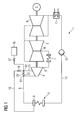
- the steam power plant 1 comprises a steam generator 2.
- Another name for a steam generator 2 is boiler 2.
- the steam generator 2 comprises a collecting tank 3, in which the steam can be collected.
- the steam power plant 1 comprises a high-pressure turbine section 4, a medium-pressure turbine section 5 and a low-pressure turbine section 6.
- a high-pressure turbine section 4 is defined such that it is present when the steam flowing out of the high-pressure turbine section 4 is heated in a reheater 7 and subsequently flows into a medium-pressure turbine section 5.
- live steam is generated, which is supplied via a line 8 of the high-pressure turbine section 4.
- the high-pressure turbine section 4 as an embodiment of a steam turbine, comprises a plurality of stages.
- steam flows to the reheater 7 and is heated there and then fed to the inflow 10 of the medium-pressure turbine section 5.
- the medium-pressure turbine part 5 the steam continues to relax, where it flows after exiting the medium-pressure turbine section 5 in the low-pressure turbine section 6.
- the steam flows into a condenser 11, where it condenses to water.
- the condensed water is passed via a further line 13 to the steam generator 2.
- the high-pressure turbine section 4 is operated such that after an intermediate stage 14, a cooling medium is supplied.
- the steam power plant 1 a cooling medium supply 15, which opens into the high-pressure turbine section 4 after the intermediate stage 14.
- the cooling medium is formed from a mixture of motive steam and water.
- the water is removed from a water reservoir 16, which can be added via a valve 17 to the motive steam.
- the motive steam is taken from a branch line 18, which opens into the sump 3 of the steam generator 2.
- live steam from the steam generator 2 via the branch line 18 and a valve 19 at the node 20 is mixed with the water from the water reservoir 16 and over the cooling medium supply 15 is guided after the intermediate stage 14 in the high-pressure turbine section 4.
- the branch line 18 and the valve 19 can be omitted and for the motive steam from the line 8 at the branch node 21 via a bypass line 22 and a valve 23 to the node 20 are supplied.
- the mass flow of the motive steam and the water can be adjusted via throttles, which are not shown in detail and the valves 17, 19, 23.
- the throttles and / or the valves 17, 19, 23 can be coupled to a control system that regulates the flow rate.
- the control can be carried out in such a way that with increasing time after reaching a minimum load, the flow rate is gradually reduced and finally turned off completely.
- the steam turbine 4 is in this case operated in such a way that the cooling medium is supplied to the high-pressure turbine section 4 during idling operation or during low-load operation.
- the cooling medium is supplied during a start-up operation until a synchronization and / or a minimum power is reached.
- Synchronization means synchronization with the mains frequency.
- Under minimum performance is to be understood as a performance at which the high-pressure turbine gives off sufficient power and thus has low evaporation temperatures.
- the high-pressure turbine section 4 comprises an outer housing 24 and an inner housing 25.
- a plurality of guide vanes 26 are arranged on the inner housing 25, with only one guide vane being provided with the reference numeral 26 for reasons of clarity.
- a rotor 27 is rotatably mounted within the inner housing 25, a rotor 27 is rotatably mounted.
- the rotor 27 includes a plurality of blades 28, for clarity only a blade has been provided with the reference numeral 28.
- the high-pressure turbine part 4 has an inflow 29 into which the live steam is supplied from the steam generator 2.
- the thus supplied live steam is passed through the guide vanes 26 and blades 28, wherein the live steam relaxes and the temperature drops.
- a flow channel 30 is formed, which ends in a Ausströmstutzen 31.
- the high-pressure turbine section 4 is designed such that a cooling medium supply 15 is arranged such that the cooling medium can be guided into the flow channel 30 after the intermediate stage 14.
- the region up to the intermediate stage 14, in particular the region around the inflow 29, is particularly stressed thermally and should therefore be made of a nickel-based alloy.
- a cooling of the flow medium in the flow channel 30 takes place, which causes the temperature in the outflow region 32 to be lowered and therefore a more favorable material than the nickel-based alloy can be used .
- the rotor 27 can therefore be made of two components, wherein the first component 33 of the nickel-based alloy and the second component 34 can be made of a more favorable material.
- the first component 33 and the second component 34 are connected to each other by means of a weld 35.
- the steam power plant 1 can be additionally cooled by the supply of an additional cooling medium after a second stage.
- the second stage is in the FIG. 2 not shown in detail, but is seen in the flow direction after the intermediate stage 14.
- the additional cooling medium is diverted from the cooling medium.
- the high-pressure turbine section 4 is designed in such a way that the guide vanes 26 of the second stage have channels.
- these second-stage vanes 26 are more or less hollow, and the cavity can be filled with the auxiliary cooling medium.
- the supplemental cooling medium flows from these channels out of the second stage vane 26 and mixes with the flow medium in the flow channel 30. This means that from this point, after the second stage, a further cooling of the flow medium takes place and from this point the thermal load is reduced.
- High-pressure turbine part 4 are formed in some embodiments with a Dampfanzapststutzen.
- This Dampfanzapststutzen be used as a tap in the normal load operation of the high-pressure turbine section 4, wherein via the Dampfanzapststutzen steam is discharged from the flow channel 30.
- this Dampfanzapststutzen is quasi transformed to the cooling medium, via which the cooling medium enters the high-pressure turbine section 4.
- the Dampfanzapststutzen therefore has a dual function. On the one hand for discharging steam from the flow channel 30 in load operation and on the other hand for supplying cooling medium during a light load operation or idle.
- the high-pressure turbine part 4 comprises the second stage, which is fluidically connected to an additional cooling medium supply.
- the additional cooling medium supply is fluidically connected to the steam generator 2 and the water reservoir 16, which in the FIG. 1 not shown in detail.
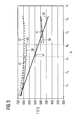
- FIG. 3 is the temperature profile within the high-pressure turbine section 4 as a function of the number of stages N (n 1 - n 7 ) shown.
- the stages n 1 , n 2 ,..., N 7 represent positive integers corresponding to the number of stages.
- the exact number of stages is not necessary for a detailed understanding of the invention, therefore the number of stages has been replaced by indices 1 to 7.
- the curve 36 shows the temperature profile as a function of the stages in normal operation. It can clearly be seen that the temperature of approx. 700 ° C to about 420 ° C after level n 6 drops. This is done by thermodynamic transformations, whereby the live steam is relaxed and the temperature is lowered.
- the second curve 37 shows the course of the temperature as a function of the steps N during idling or low-load operation when no measures according to the invention are carried out.
- the third curve 38 shows the curve of the temperature T as a function of the stages N in the light load or idling mode, if after the stage n 4 , which is to be understood as an intermediate stage 14, that cooling medium of the high-pressure turbine section 4 is supplied.
- the vertical dashed line shows very clearly that the temperature at the point shows a significant jump from approx. 630 ° C to 470 ° C. This means that from this point, the high-pressure turbine section 4 is less thermally stressed because the temperatures in this range does not rise above 500 ° C.
- the fourth curve 41 shows the temperature profile T as a function of the stages N when the intermediate stage 14 takes place at the position n 3 and at the location n 4 the additional cooling medium is additionally supplied after the second stage. It can be clearly seen that after the intermediate stage 14, ie in the illustration according to FIG. 3 shortly after stage n 3, the temperature drops abruptly from about 640 ° C to 540 ° C and then after the further supply of additional additional cooling medium, the temperature of about 530 ° C to 490 ° C drops.
Landscapes
- Engineering & Computer Science (AREA)
- Mechanical Engineering (AREA)
- General Engineering & Computer Science (AREA)
- Chemical & Material Sciences (AREA)
- Combustion & Propulsion (AREA)
- Materials Engineering (AREA)
- Control Of Turbines (AREA)
- Turbine Rotor Nozzle Sealing (AREA)
Priority Applications (7)
| Application Number | Priority Date | Filing Date | Title |
|---|---|---|---|
| EP07003922A EP1998014A3 (fr) | 2007-02-26 | 2007-02-26 | Procédé destiné au fonctionnement d'une turbine à vapeur multiple |
| EP08709020A EP2129879A2 (fr) | 2007-02-26 | 2008-02-15 | Procédé de fonctionnement d'une turbine à vapeur à plusieurs étages |
| PCT/EP2008/051834 WO2008104465A2 (fr) | 2007-02-26 | 2008-02-15 | Procédé de fonctionnement d'une turbine à vapeur à plusieurs étages |
| CN2008800062161A CN101622424B (zh) | 2007-02-26 | 2008-02-15 | 用于运行多级的蒸汽涡轮机的方法 |
| US12/528,349 US8713941B2 (en) | 2007-02-26 | 2008-02-15 | Method for operating a multi-step steam turbine |
| JP2009550265A JP5066194B2 (ja) | 2007-02-26 | 2008-02-15 | 多段蒸気タービンの運転方法 |
| US14/176,419 US20140150431A1 (en) | 2007-02-26 | 2014-02-10 | Steam power plant having a multi-stage steam turbine |
Applications Claiming Priority (1)
| Application Number | Priority Date | Filing Date | Title |
|---|---|---|---|
| EP07003922A EP1998014A3 (fr) | 2007-02-26 | 2007-02-26 | Procédé destiné au fonctionnement d'une turbine à vapeur multiple |
Publications (2)
| Publication Number | Publication Date |
|---|---|
| EP1998014A2 true EP1998014A2 (fr) | 2008-12-03 |
| EP1998014A3 EP1998014A3 (fr) | 2008-12-31 |
Family
ID=39721643
Family Applications (2)
| Application Number | Title | Priority Date | Filing Date |
|---|---|---|---|
| EP07003922A Withdrawn EP1998014A3 (fr) | 2007-02-26 | 2007-02-26 | Procédé destiné au fonctionnement d'une turbine à vapeur multiple |
| EP08709020A Withdrawn EP2129879A2 (fr) | 2007-02-26 | 2008-02-15 | Procédé de fonctionnement d'une turbine à vapeur à plusieurs étages |
Family Applications After (1)
| Application Number | Title | Priority Date | Filing Date |
|---|---|---|---|
| EP08709020A Withdrawn EP2129879A2 (fr) | 2007-02-26 | 2008-02-15 | Procédé de fonctionnement d'une turbine à vapeur à plusieurs étages |
Country Status (5)
| Country | Link |
|---|---|
| US (2) | US8713941B2 (fr) |
| EP (2) | EP1998014A3 (fr) |
| JP (1) | JP5066194B2 (fr) |
| CN (1) | CN101622424B (fr) |
| WO (1) | WO2008104465A2 (fr) |
Families Citing this family (10)
| Publication number | Priority date | Publication date | Assignee | Title |
|---|---|---|---|---|
| DE102008033402A1 (de) * | 2008-07-16 | 2010-01-21 | Siemens Aktiengesellschaft | Dampfturbinenanlage sowie Verfahren zum Betreiben einer Dampfturbine |
| EP2147896A1 (fr) * | 2008-07-22 | 2010-01-27 | Uhde GmbH | Procedé à basse énergie pour la production d'ammoniac ou de méthanol |
| JP5615150B2 (ja) * | 2010-12-06 | 2014-10-29 | 三菱重工業株式会社 | 原子力発電プラントおよび原子力発電プラントの運転方法 |
| EP2565401A1 (fr) * | 2011-09-05 | 2013-03-06 | Siemens Aktiengesellschaft | Procédé d'équilibrage des températures dans une turbine à gaz |
| EP2647802A1 (fr) * | 2012-04-04 | 2013-10-09 | Siemens Aktiengesellschaft | Centrale électrique et procédé destiné au fonctionnement d'une centrale électrique |
| EP2657467A1 (fr) * | 2012-04-27 | 2013-10-30 | Siemens Aktiengesellschaft | Refroidissement forcé pour installations de turbines à vapeur |
| CN103089346B (zh) * | 2012-12-28 | 2015-02-18 | 东方电气集团东方汽轮机有限公司 | 汽轮机组强迫冷却系统 |
| EP3015644B1 (fr) * | 2014-10-29 | 2018-12-12 | General Electric Technology GmbH | Rotor de turbine à vapeur |
| CN106194284B (zh) * | 2016-07-22 | 2017-07-28 | 东方电气集团东方汽轮机有限公司 | 一种汽轮机夹层蒸汽参数调整及运行的方法 |
| DE102018219374A1 (de) * | 2018-11-13 | 2020-05-14 | Siemens Aktiengesellschaft | Dampfturbine und Verfahren zum Betreiben derselben |
Family Cites Families (14)
| Publication number | Priority date | Publication date | Assignee | Title |
|---|---|---|---|---|
| US3898842A (en) * | 1972-01-27 | 1975-08-12 | Westinghouse Electric Corp | Electric power plant system and method for operating a steam turbine especially of the nuclear type with electronic reheat control of a cycle steam reheater |
| DD148367A1 (de) * | 1979-12-29 | 1981-05-20 | Karl Speicher | Einrichtung zur ueberdrehzahlminderung einer dampfturbine nach lastabwurf |
| JPS58140408A (ja) * | 1982-02-17 | 1983-08-20 | Hitachi Ltd | 蒸気タ−ビンの冷却装置 |
| JPH0621521B2 (ja) * | 1983-06-10 | 1994-03-23 | 株式会社日立製作所 | 蒸気タ−ビンの主蒸気入口構造 |
| DE4129518A1 (de) * | 1991-09-06 | 1993-03-11 | Siemens Ag | Kuehlung einer niederbruck-dampfturbine im ventilationsbetrieb |
| JP2990985B2 (ja) * | 1992-12-16 | 1999-12-13 | 富士電機株式会社 | 蒸気タービンの翼温度上昇防止装置 |
| JPH0849507A (ja) * | 1994-08-09 | 1996-02-20 | Fuji Electric Co Ltd | 抽気タービンの内部冷却方法 |
| DE19506787B4 (de) * | 1995-02-27 | 2004-05-06 | Alstom | Verfahren zum Betrieb einer Dampfturbine |
| US5953900A (en) * | 1996-09-19 | 1999-09-21 | Siemens Westinghouse Power Corporation | Closed loop steam cooled steam turbine |
| DE19823251C1 (de) * | 1998-05-26 | 1999-07-08 | Siemens Ag | Verfahren und Vorrichtung zur Kühlung einer Niederdruckstufe einer Dampfturbine |
| EP1152125A1 (fr) * | 2000-05-05 | 2001-11-07 | Siemens Aktiengesellschaft | Méthode et dispositif pour le refroidissement de la partie antérieure de l'arbre d'une turbine à vapeur |
| CN100406685C (zh) | 2003-04-30 | 2008-07-30 | 株式会社东芝 | 中压蒸汽轮机、蒸汽轮机发电厂及其运转方法 |
| EP1674669A1 (fr) * | 2004-12-21 | 2006-06-28 | Siemens Aktiengesellschaft | Procédé de refroidissement de turbine à vapeur |
| JP5049578B2 (ja) * | 2006-12-15 | 2012-10-17 | 株式会社東芝 | 蒸気タービン |
-
2007
- 2007-02-26 EP EP07003922A patent/EP1998014A3/fr not_active Withdrawn
-
2008
- 2008-02-15 CN CN2008800062161A patent/CN101622424B/zh not_active Expired - Fee Related
- 2008-02-15 US US12/528,349 patent/US8713941B2/en not_active Expired - Fee Related
- 2008-02-15 JP JP2009550265A patent/JP5066194B2/ja not_active Expired - Fee Related
- 2008-02-15 EP EP08709020A patent/EP2129879A2/fr not_active Withdrawn
- 2008-02-15 WO PCT/EP2008/051834 patent/WO2008104465A2/fr not_active Ceased
-
2014
- 2014-02-10 US US14/176,419 patent/US20140150431A1/en not_active Abandoned
Also Published As
| Publication number | Publication date |
|---|---|
| WO2008104465A2 (fr) | 2008-09-04 |
| CN101622424B (zh) | 2013-06-19 |
| JP2010519452A (ja) | 2010-06-03 |
| EP1998014A3 (fr) | 2008-12-31 |
| EP2129879A2 (fr) | 2009-12-09 |
| US8713941B2 (en) | 2014-05-06 |
| US20140150431A1 (en) | 2014-06-05 |
| JP5066194B2 (ja) | 2012-11-07 |
| CN101622424A (zh) | 2010-01-06 |
| WO2008104465A3 (fr) | 2009-01-29 |
| US20110005224A1 (en) | 2011-01-13 |
Similar Documents
| Publication | Publication Date | Title |
|---|---|---|
| EP1998014A2 (fr) | Procédé destiné au fonctionnement d'une turbine à vapeur multiple | |
| DE102008037410B4 (de) | Superkritischen Dampf verwendender kombinierter Kreisprozess und Verfahren | |
| DE60126721T2 (de) | Kombiniertes Kreislaufsystem mit Gasturbine | |
| DE102008029941B4 (de) | Dampfkraftanlage und Verfahren zur Regelung der Leistung einer Dampfkraftanlage | |
| DE19513285B4 (de) | Turbinen-Antrieb für Kesselspeisepumpe / Speisewasser-Leitungssystem | |
| EP2480762B1 (fr) | Centrale thermique comprenant vanne de régulation de surcharge | |
| EP1934434B1 (fr) | Procédé pour chauffer une turbine à vapeur | |
| EP1368555B1 (fr) | Procede d'utilisation d'un groupe vapeur et groupe vapeur correspondant | |
| CH702740B1 (de) | System und Verfahren zum Hochfahren eines Wärmerückgewinnungsdampfgenerators. | |
| EP1320663A1 (fr) | Procede et dispositif pour rechauffer et purger des conduites d'amenee de vapeur raccordees a des turbines a vapeur | |
| EP2326800B1 (fr) | Centrale à vapeur destinée à la production d'énergie électrique | |
| EP2322768B1 (fr) | Centrale à vapeur et procédé de fonctionnement d'une centrale à vapeur | |
| EP3810907B1 (fr) | Recirculation des gaz d'échappement dans des installations de turbines à gaz et à vapeur | |
| DE102010009130A1 (de) | Dampfkraftwerk umfassend eine Tuning-Turbine | |
| DE102016112601A1 (de) | Vorrichtung zur Energieerzeugung nach dem ORC-Prinzip, Geothermieanlage mit einer solchen Vorrichtung und Betriebsverfahren | |
| EP2556218B1 (fr) | Procédé de raccordement rapide d'un générateur de vapeur | |
| WO2007144285A2 (fr) | Centrale à vapeur | |
| EP4070011A1 (fr) | Installation comprenant un module auxiliaire | |
| EP1953351A1 (fr) | Concept de préchauffage et de démarrage de turbines à vapeur avec des températures d'entrée supérieures à 650°C | |
| EP1674669A1 (fr) | Procédé de refroidissement de turbine à vapeur | |
| EP3365534B1 (fr) | Procédé de préchauffage d'eau d'alimentation d'une chaudière à vapeur d'une centrale électrique et centrale à vapeur pour la mise en oeuvre du procédé | |
| DE102014211976A1 (de) | Verfahren zum Anfahren eines Dampfturbinensystems | |
| DE10124492B4 (de) | Verfahren zum Betrieb eines Kombikraftwerkes bei unterschiedlichen Netzanforderungen | |
| DE69808727T2 (de) | Kühldampfsystem für dampfgekühlte Gasturbine | |
| WO2018166828A1 (fr) | Structure d'enveloppe intérieure dotée d'une chambre de condensation pour turbine à vapeur |
Legal Events
| Date | Code | Title | Description |
|---|---|---|---|
| PUAI | Public reference made under article 153(3) epc to a published international application that has entered the european phase |
Free format text: ORIGINAL CODE: 0009012 |
|
| PUAL | Search report despatched |
Free format text: ORIGINAL CODE: 0009013 |
|
| AK | Designated contracting states |
Kind code of ref document: A2 Designated state(s): AT BE BG CH CY CZ DE DK EE ES FI FR GB GR HU IE IS IT LI LT LU LV MC NL PL PT RO SE SI SK TR |
|
| AX | Request for extension of the european patent |
Extension state: AL BA HR MK RS |
|
| RIC1 | Information provided on ipc code assigned before grant |
Ipc: F01D 25/12 20060101ALI20081120BHEP Ipc: F01K 13/00 20060101ALI20081120BHEP Ipc: F01K 7/16 20060101ALI20081120BHEP Ipc: F01K 13/02 20060101AFI20081120BHEP |
|
| AK | Designated contracting states |
Kind code of ref document: A3 Designated state(s): AT BE BG CH CY CZ DE DK EE ES FI FR GB GR HU IE IS IT LI LT LU LV MC NL PL PT RO SE SI SK TR |
|
| AX | Request for extension of the european patent |
Extension state: AL BA HR MK RS |
|
| AKX | Designation fees paid | ||
| STAA | Information on the status of an ep patent application or granted ep patent |
Free format text: STATUS: THE APPLICATION IS DEEMED TO BE WITHDRAWN |
|
| 18D | Application deemed to be withdrawn |
Effective date: 20090701 |
|
| REG | Reference to a national code |
Ref country code: DE Ref legal event code: 8566 |