EP1998014A2 - Method for operating a multi-stage steam turbine - Google Patents
Method for operating a multi-stage steam turbine Download PDFInfo
- Publication number
- EP1998014A2 EP1998014A2 EP07003922A EP07003922A EP1998014A2 EP 1998014 A2 EP1998014 A2 EP 1998014A2 EP 07003922 A EP07003922 A EP 07003922A EP 07003922 A EP07003922 A EP 07003922A EP 1998014 A2 EP1998014 A2 EP 1998014A2
- Authority
- EP
- European Patent Office
- Prior art keywords
- cooling medium
- steam
- power plant
- supply
- stage
- Prior art date
- Legal status (The legal status is an assumption and is not a legal conclusion. Google has not performed a legal analysis and makes no representation as to the accuracy of the status listed.)
- Withdrawn
Links
Images

Classifications
-
- F—MECHANICAL ENGINEERING; LIGHTING; HEATING; WEAPONS; BLASTING
- F01—MACHINES OR ENGINES IN GENERAL; ENGINE PLANTS IN GENERAL; STEAM ENGINES
- F01K—STEAM ENGINE PLANTS; STEAM ACCUMULATORS; ENGINE PLANTS NOT OTHERWISE PROVIDED FOR; ENGINES USING SPECIAL WORKING FLUIDS OR CYCLES
- F01K13/00—General layout or general methods of operation of complete plants
- F01K13/02—Controlling, e.g. stopping or starting
-
- F—MECHANICAL ENGINEERING; LIGHTING; HEATING; WEAPONS; BLASTING
- F01—MACHINES OR ENGINES IN GENERAL; ENGINE PLANTS IN GENERAL; STEAM ENGINES
- F01D—NON-POSITIVE DISPLACEMENT MACHINES OR ENGINES, e.g. STEAM TURBINES
- F01D5/00—Blades; Blade-carrying members; Heating, heat-insulating, cooling or antivibration means on the blades or the members
- F01D5/12—Blades
- F01D5/28—Selecting particular materials; Particular measures relating thereto; Measures against erosion or corrosion
-
- F—MECHANICAL ENGINEERING; LIGHTING; HEATING; WEAPONS; BLASTING
- F01—MACHINES OR ENGINES IN GENERAL; ENGINE PLANTS IN GENERAL; STEAM ENGINES
- F01D—NON-POSITIVE DISPLACEMENT MACHINES OR ENGINES, e.g. STEAM TURBINES
- F01D25/00—Component parts, details, or accessories, not provided for in, or of interest apart from, other groups
- F01D25/08—Cooling; Heating; Heat-insulation
- F01D25/12—Cooling
-
- F—MECHANICAL ENGINEERING; LIGHTING; HEATING; WEAPONS; BLASTING
- F01—MACHINES OR ENGINES IN GENERAL; ENGINE PLANTS IN GENERAL; STEAM ENGINES
- F01D—NON-POSITIVE DISPLACEMENT MACHINES OR ENGINES, e.g. STEAM TURBINES
- F01D25/00—Component parts, details, or accessories, not provided for in, or of interest apart from, other groups
- F01D25/08—Cooling; Heating; Heat-insulation
- F01D25/14—Casings modified therefor
-
- F—MECHANICAL ENGINEERING; LIGHTING; HEATING; WEAPONS; BLASTING
- F01—MACHINES OR ENGINES IN GENERAL; ENGINE PLANTS IN GENERAL; STEAM ENGINES
- F01D—NON-POSITIVE DISPLACEMENT MACHINES OR ENGINES, e.g. STEAM TURBINES
- F01D25/00—Component parts, details, or accessories, not provided for in, or of interest apart from, other groups
- F01D25/24—Casings; Casing parts, e.g. diaphragms, casing fastenings
- F01D25/26—Double casings; Measures against temperature strain in casings
-
- F—MECHANICAL ENGINEERING; LIGHTING; HEATING; WEAPONS; BLASTING
- F01—MACHINES OR ENGINES IN GENERAL; ENGINE PLANTS IN GENERAL; STEAM ENGINES
- F01K—STEAM ENGINE PLANTS; STEAM ACCUMULATORS; ENGINE PLANTS NOT OTHERWISE PROVIDED FOR; ENGINES USING SPECIAL WORKING FLUIDS OR CYCLES
- F01K13/00—General layout or general methods of operation of complete plants
- F01K13/006—Auxiliaries or details not otherwise provided for
-
- F—MECHANICAL ENGINEERING; LIGHTING; HEATING; WEAPONS; BLASTING
- F01—MACHINES OR ENGINES IN GENERAL; ENGINE PLANTS IN GENERAL; STEAM ENGINES
- F01K—STEAM ENGINE PLANTS; STEAM ACCUMULATORS; ENGINE PLANTS NOT OTHERWISE PROVIDED FOR; ENGINES USING SPECIAL WORKING FLUIDS OR CYCLES
- F01K13/00—General layout or general methods of operation of complete plants
- F01K13/02—Controlling, e.g. stopping or starting
- F01K13/025—Cooling the interior by injection during idling or stand-by
-
- F—MECHANICAL ENGINEERING; LIGHTING; HEATING; WEAPONS; BLASTING
- F01—MACHINES OR ENGINES IN GENERAL; ENGINE PLANTS IN GENERAL; STEAM ENGINES
- F01K—STEAM ENGINE PLANTS; STEAM ACCUMULATORS; ENGINE PLANTS NOT OTHERWISE PROVIDED FOR; ENGINES USING SPECIAL WORKING FLUIDS OR CYCLES
- F01K7/00—Steam engine plants characterised by the use of specific types of engine; Plants or engines characterised by their use of special steam systems, cycles or processes; Control means specially adapted for such systems, cycles or processes; Use of withdrawn or exhaust steam for feed-water heating
- F01K7/16—Steam engine plants characterised by the use of specific types of engine; Plants or engines characterised by their use of special steam systems, cycles or processes; Control means specially adapted for such systems, cycles or processes; Use of withdrawn or exhaust steam for feed-water heating the engines being only of turbine type
-
- F—MECHANICAL ENGINEERING; LIGHTING; HEATING; WEAPONS; BLASTING
- F05—INDEXING SCHEMES RELATING TO ENGINES OR PUMPS IN VARIOUS SUBCLASSES OF CLASSES F01-F04
- F05D—INDEXING SCHEME FOR ASPECTS RELATING TO NON-POSITIVE-DISPLACEMENT MACHINES OR ENGINES, GAS-TURBINES OR JET-PROPULSION PLANTS
- F05D2220/00—Application
- F05D2220/30—Application in turbines
- F05D2220/31—Application in turbines in steam turbines
-
- F—MECHANICAL ENGINEERING; LIGHTING; HEATING; WEAPONS; BLASTING
- F05—INDEXING SCHEMES RELATING TO ENGINES OR PUMPS IN VARIOUS SUBCLASSES OF CLASSES F01-F04
- F05D—INDEXING SCHEME FOR ASPECTS RELATING TO NON-POSITIVE-DISPLACEMENT MACHINES OR ENGINES, GAS-TURBINES OR JET-PROPULSION PLANTS
- F05D2260/00—Function
- F05D2260/20—Heat transfer, e.g. cooling
- F05D2260/232—Heat transfer, e.g. cooling characterized by the cooling medium
Definitions
- the invention relates to a method for operating a multi-stage steam turbine and a steam power plant, comprising a multi-stage steam turbine, a boiler and a cooling medium supply.
- the rotor could be designed as a welded construction, a nickel-based alloy being used in the live steam region and a conventional material being used in the exhaust steam region.
- a manufactured high-pressure turbine part would be in operation withstand occurring loads.
- the steam temperatures in the exhaust-steam region of the high-pressure turbine during an idling operation or low-load operation are comparatively high, as a result of which the conventional material is thermally stressed too much. This problem occurs in particular during a hot start, since the steam temperatures can not be lowered arbitrarily in order to limit the thermal load of the inflow.
- the invention begins, whose object is to provide a method for operating a steam turbine and a steam power plant, wherein the steam turbine can be produced inexpensively.
- the object directed to the method is achieved by a method for operating a multi-stage steam turbine, the steam turbine being supplied with live steam and after an intermediate stage with a cooling medium.
- the invention is based on the aspect that a high-pressure turbine section in the exhaust steam region can be made of a conventional material if the exhaust steam zone is suitably cooled in idle or light load operation.
- the invention is carried out in which after the intermediate stage in the steam turbine, a cooling medium is supplied.
- the area of the steam turbine is cooled after this intermediate stage.
- the existing before this intermediate section of the steam turbine can be made of a nickel-based alloy, wherein the material used in the Abdampf Jardin can be made of a conventional material, since the temperatures in the exhaust steam can now be selectively lowered.
- the cooling medium is formed from a mixture of motive steam and water.
- the motive steam is removed from the boiler.
- the boiler which is also referred to as a steam generator, can be easily converted to receive motive steam.
- the motive steam can be diverted via a bypass line from the live steam supply. This would be in addition to the branch directly from the boiler another simple and inexpensive way to provide a suitable motive steam that can be used by the addition of water as the cooling medium in the steam turbine.
- the cooling medium is supplied in idle mode or in low load operation.
- the cooling medium is supplied in particular at the beginning of a hot start.
- the temperature of the materials of the high-pressure turbine part is comparatively high, so that when a hot start of the live steam, the entire high-pressure turbine section thermally loaded.
- the high-pressure turbine part during a hot start particularly thermally stressed.
- the cooling medium is supplied during a starting operation until a synchronization and / or a minimum power is reached.
- This has the advantage that the high-pressure steam temperature can be kept constant by controlling the cooling medium mass flow.
- the steam turbine is developed in such a way that after a second stage, an additional cooling medium is additionally supplied.
- the additional cooling medium is in this case preferably diverted from the cooling medium, which is a cost-effective way to convert an existing power plant.
- the additional cooling medium is emitted from a channel mounted in a guide vane. This makes it possible, so to speak, to let additional cooling medium flow quickly and over a large area into the flow channel of the turbomachine.
- the mixing of the additional cooling medium with the flow medium is in this case comparatively high, so that the temperature is suddenly reduced.
- the task directed towards the steam power plant is achieved by a steam power plant comprising a multi-stage steam turbine, a boiler and a cooling medium feed, the cooling medium feed discharging into the steam turbine after an intermediate stage.
- a steam power plant comprising a multi-stage steam turbine, a boiler and a cooling medium feed, the cooling medium feed discharging into the steam turbine after an intermediate stage.
- the cooling medium supply is fluidically connected to the boiler and a water reservoir.
- the cooling medium supply is fluidically connected to a bypass line from a live steam supply line and a water reservoir.
- the steam turbine to a second stage, which is fluidly connected to a Budapest mark.
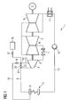
- the steam power plant 1 comprises a steam generator 2.
- Another name for a steam generator 2 is boiler 2.
- the steam generator 2 comprises a collecting tank 3, in which the steam can be collected.
- the steam power plant 1 comprises a high-pressure turbine section 4, a medium-pressure turbine section 5 and a low-pressure turbine section 6.
- a high-pressure turbine section 4 is defined such that it is present when the steam flowing out of the high-pressure turbine section 4 is heated in a reheater 7 and subsequently flows into a medium-pressure turbine section 5.
- live steam is generated, which is supplied via a line 8 of the high-pressure turbine section 4.
- the high-pressure turbine section 4 as an embodiment of a steam turbine, comprises a plurality of stages.
- steam flows to the reheater 7 and is heated there and then fed to the inflow 10 of the medium-pressure turbine section 5.
- the medium-pressure turbine part 5 the steam continues to relax, where it flows after exiting the medium-pressure turbine section 5 in the low-pressure turbine section 6.
- the steam flows into a condenser 11, where it condenses to water.
- the condensed water is passed via a further line 13 to the steam generator 2.
- the high-pressure turbine section 4 is operated such that after an intermediate stage 14, a cooling medium is supplied.
- the steam power plant 1 a cooling medium supply 15, which opens into the high-pressure turbine section 4 after the intermediate stage 14.
- the cooling medium is formed from a mixture of motive steam and water.
- the water is removed from a water reservoir 16, which can be added via a valve 17 to the motive steam.
- the motive steam is taken from a branch line 18, which opens into the sump 3 of the steam generator 2.
- live steam from the steam generator 2 via the branch line 18 and a valve 19 at the node 20 is mixed with the water from the water reservoir 16 and over the cooling medium supply 15 is guided after the intermediate stage 14 in the high-pressure turbine section 4.
- the branch line 18 and the valve 19 can be omitted and for the motive steam from the line 8 at the branch node 21 via a bypass line 22 and a valve 23 to the node 20 are supplied.
- the mass flow of the motive steam and the water can be adjusted via throttles, which are not shown in detail and the valves 17, 19, 23.
- the throttles and / or the valves 17, 19, 23 can be coupled to a control system that regulates the flow rate.
- the control can be carried out in such a way that with increasing time after reaching a minimum load, the flow rate is gradually reduced and finally turned off completely.
- the steam turbine 4 is in this case operated in such a way that the cooling medium is supplied to the high-pressure turbine section 4 during idling operation or during low-load operation.
- the cooling medium is supplied during a start-up operation until a synchronization and / or a minimum power is reached.
- Synchronization means synchronization with the mains frequency.
- Under minimum performance is to be understood as a performance at which the high-pressure turbine gives off sufficient power and thus has low evaporation temperatures.
- the high-pressure turbine section 4 comprises an outer housing 24 and an inner housing 25.
- a plurality of guide vanes 26 are arranged on the inner housing 25, with only one guide vane being provided with the reference numeral 26 for reasons of clarity.
- a rotor 27 is rotatably mounted within the inner housing 25, a rotor 27 is rotatably mounted.
- the rotor 27 includes a plurality of blades 28, for clarity only a blade has been provided with the reference numeral 28.
- the high-pressure turbine part 4 has an inflow 29 into which the live steam is supplied from the steam generator 2.
- the thus supplied live steam is passed through the guide vanes 26 and blades 28, wherein the live steam relaxes and the temperature drops.
- a flow channel 30 is formed, which ends in a Ausströmstutzen 31.
- the high-pressure turbine section 4 is designed such that a cooling medium supply 15 is arranged such that the cooling medium can be guided into the flow channel 30 after the intermediate stage 14.
- the region up to the intermediate stage 14, in particular the region around the inflow 29, is particularly stressed thermally and should therefore be made of a nickel-based alloy.
- a cooling of the flow medium in the flow channel 30 takes place, which causes the temperature in the outflow region 32 to be lowered and therefore a more favorable material than the nickel-based alloy can be used .
- the rotor 27 can therefore be made of two components, wherein the first component 33 of the nickel-based alloy and the second component 34 can be made of a more favorable material.
- the first component 33 and the second component 34 are connected to each other by means of a weld 35.
- the steam power plant 1 can be additionally cooled by the supply of an additional cooling medium after a second stage.
- the second stage is in the FIG. 2 not shown in detail, but is seen in the flow direction after the intermediate stage 14.
- the additional cooling medium is diverted from the cooling medium.
- the high-pressure turbine section 4 is designed in such a way that the guide vanes 26 of the second stage have channels.
- these second-stage vanes 26 are more or less hollow, and the cavity can be filled with the auxiliary cooling medium.
- the supplemental cooling medium flows from these channels out of the second stage vane 26 and mixes with the flow medium in the flow channel 30. This means that from this point, after the second stage, a further cooling of the flow medium takes place and from this point the thermal load is reduced.
- High-pressure turbine part 4 are formed in some embodiments with a Dampfanzapststutzen.
- This Dampfanzapststutzen be used as a tap in the normal load operation of the high-pressure turbine section 4, wherein via the Dampfanzapststutzen steam is discharged from the flow channel 30.
- this Dampfanzapststutzen is quasi transformed to the cooling medium, via which the cooling medium enters the high-pressure turbine section 4.
- the Dampfanzapststutzen therefore has a dual function. On the one hand for discharging steam from the flow channel 30 in load operation and on the other hand for supplying cooling medium during a light load operation or idle.
- the high-pressure turbine part 4 comprises the second stage, which is fluidically connected to an additional cooling medium supply.
- the additional cooling medium supply is fluidically connected to the steam generator 2 and the water reservoir 16, which in the FIG. 1 not shown in detail.
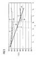
- FIG. 3 is the temperature profile within the high-pressure turbine section 4 as a function of the number of stages N (n 1 - n 7 ) shown.
- the stages n 1 , n 2 ,..., N 7 represent positive integers corresponding to the number of stages.
- the exact number of stages is not necessary for a detailed understanding of the invention, therefore the number of stages has been replaced by indices 1 to 7.
- the curve 36 shows the temperature profile as a function of the stages in normal operation. It can clearly be seen that the temperature of approx. 700 ° C to about 420 ° C after level n 6 drops. This is done by thermodynamic transformations, whereby the live steam is relaxed and the temperature is lowered.
- the second curve 37 shows the course of the temperature as a function of the steps N during idling or low-load operation when no measures according to the invention are carried out.
- the third curve 38 shows the curve of the temperature T as a function of the stages N in the light load or idling mode, if after the stage n 4 , which is to be understood as an intermediate stage 14, that cooling medium of the high-pressure turbine section 4 is supplied.
- the vertical dashed line shows very clearly that the temperature at the point shows a significant jump from approx. 630 ° C to 470 ° C. This means that from this point, the high-pressure turbine section 4 is less thermally stressed because the temperatures in this range does not rise above 500 ° C.
- the fourth curve 41 shows the temperature profile T as a function of the stages N when the intermediate stage 14 takes place at the position n 3 and at the location n 4 the additional cooling medium is additionally supplied after the second stage. It can be clearly seen that after the intermediate stage 14, ie in the illustration according to FIG. 3 shortly after stage n 3, the temperature drops abruptly from about 640 ° C to 540 ° C and then after the further supply of additional additional cooling medium, the temperature of about 530 ° C to 490 ° C drops.
Abstract
Description
Die Erfindung betrifft ein Verfahren zum Betreiben einer mehrstufigen Dampfturbine sowie eine Dampfkraftanlage, umfassend eine mehrstufige Dampfturbine, einen Kessel und eine Kühlmediumzuführung.The invention relates to a method for operating a multi-stage steam turbine and a steam power plant, comprising a multi-stage steam turbine, a boiler and a cooling medium supply.
Aus thermodynamischen Gründen ist es erforderlich die Frischdampftemperaturen zu erhöhen, um den Wirkungsgrad von modernen Dampfturbinenanlagen zu verbessern. Derzeit werden Dampfturbinen für Frischdampftemperaturen von ca. 630°C und Frischdampfdrücke von ca. 300 bar konstruiert und gefertigt. Die Auswahl der Materialien für den Rotor und das Gehäuse spielt eine bedeutende Rolle. Der Einsatz von Nickel-Basis-Legierungen als Hochtemperaturwerkstoff für Frischdampftemperaturen von geplanten 700°C scheint möglich. Der Rotor und das Gehäuse einer für 700°C geeigneten Dampfturbine könnte somit aus einer Nickel-Basis-Legierung hergestellt werden, wobei dies eine sehr kostenintensive Lösung darstellen würde.For thermodynamic reasons, it is necessary to increase the live steam temperatures in order to improve the efficiency of modern steam turbine plants. At present, steam turbines are designed and manufactured for live steam temperatures of approx. 630 ° C and live steam pressures of approx. 300 bar. The choice of materials for the rotor and housing plays an important role. The use of nickel-based alloys as a high-temperature material for live steam temperatures of planned 700 ° C seems possible. The rotor and the housing of a suitable steam turbine for 700 ° C could thus be made of a nickel-based alloy, which would be a very costly solution.
In Hochdruck-Teilturbinen werden die Materialien in der Umgebung des Einströmbereiches extrem thermisch belastet. Im Abdampfbereich der Hochdruck-Teilturbine ist die Temperatur und der Druck des Frischdampfes gering im Vergleich zu der Temperatur und dem Druck des Frischdampfes. Der Einsatz der teuren Nickel-Basis-Legierung im Abdampfbereich ist daher nicht zwingend erforderlich.In high-pressure turbine sections, the materials in the vicinity of the inflow area are subjected to extremely high thermal loads. In the exhaust steam area of the high-pressure turbine section, the temperature and the pressure of the live steam are low compared to the temperature and the pressure of the live steam. The use of expensive nickel-based alloy in Abdampfbereich is therefore not mandatory.
Es ist daher üblich, Hochdruck-Teilturbinen aus unterschiedlichen Werkstoffen zu fertigen. So könnte beispielsweise der Rotor als Schweißkonstruktion ausgeführt werden, wobei im Frischdampfbereich eine Nickel-Basis-Legierung und im Abdampfbereich ein konventioneller Werkstoff verwendet wird. Dies würde zu insgesamt geringeren Herstellungskosten führen. Eine solch gefertigte Hochdruck-Teilturbine würde den im Betrieb auftretenden Belastungen standhalten. Allerdings sind die Dampftemperaturen im Abdampfbereich der Hochdruck-Teilturbine während eines Leerlaufbetriebes bzw. Schwachlastbetriebes vergleichsweise hoch, wodurch der konventionelle Werkstoff thermisch zu sehr belastet wird. Dieses Problem tritt insbesondere bei einem Heißstart auf, da die Frischdampftemperaturen nicht beliebig abgesenkt werden können, um die thermische Belastung der Einströmung zu begrenzen.It is therefore customary to produce high-pressure turbine parts made of different materials. Thus, for example, the rotor could be designed as a welded construction, a nickel-based alloy being used in the live steam region and a conventional material being used in the exhaust steam region. This would lead to an overall lower production cost. Such a manufactured high-pressure turbine part would be in operation withstand occurring loads. However, the steam temperatures in the exhaust-steam region of the high-pressure turbine during an idling operation or low-load operation are comparatively high, as a result of which the conventional material is thermally stressed too much. This problem occurs in particular during a hot start, since the steam temperatures can not be lowered arbitrarily in order to limit the thermal load of the inflow.
In der
Wünschenswert wäre eine aus unterschiedlichen Materialien ausgebildete Hochdruck-Teilturbine, die für unterschiedliche Lastbedingungen, wie z. B. Schwachlast oder Hochlast geeignet ist.It would be desirable formed of different materials high-pressure turbine section, for different load conditions such. B. low load or high load is suitable.
An dieser Stelle setzt die Erfindung an, deren Aufgabe es ist, ein Verfahren zum Betreiben einer Dampfturbine und eine Dampfkraftanlage anzugeben, wobei die Dampfturbine kostengünstig hergestellt werden kann.At this point, the invention begins, whose object is to provide a method for operating a steam turbine and a steam power plant, wherein the steam turbine can be produced inexpensively.
Die auf das Verfahren hin gerichtete Aufgabe wird gelöst durch ein Verfahren zum Betreiben einer mehrstufigen Dampfturbine, wobei der Dampfturbine Frischdampf und nach einer Zwischenstufe ein Kühlmedium zugeführt wird.The object directed to the method is achieved by a method for operating a multi-stage steam turbine, the steam turbine being supplied with live steam and after an intermediate stage with a cooling medium.
Die Erfindung geht von dem Aspekt aus, dass eine Hochdruck-Teilturbine im Abdampfbereich aus einem konventionellen Werkstoff ausgeführt werden kann, wenn der Abdampfbereich im Leerlauf oder Schwachlastbetrieb geeignet gekühlt wird. Die erfolgt erfindungsgemäß, in dem nach der Zwischenstufe in der Dampfturbine ein Kühlmedium zugeführt wird. Somit wird der Bereich der Dampfturbine nach dieser Zwischenstufe abgekühlt. Der vor dieser Zwischenstufe vorhandene Bereich der Dampfturbine kann aus einer Nickel-Basis-Legierung ausgeführt sein, wobei der im Abdampfbereich eingesetzte Werkstoff aus einem konventionellen Werkstoff ausgeführt werden kann, da die Temperaturen im Abdampfbereich nunmehr gezielt gesenkt werden können.The invention is based on the aspect that a high-pressure turbine section in the exhaust steam region can be made of a conventional material if the exhaust steam zone is suitably cooled in idle or light load operation. The invention is carried out in which after the intermediate stage in the steam turbine, a cooling medium is supplied. Thus, the area of the steam turbine is cooled after this intermediate stage. The existing before this intermediate section of the steam turbine can be made of a nickel-based alloy, wherein the material used in the Abdampfbereich can be made of a conventional material, since the temperatures in the exhaust steam can now be selectively lowered.
Somit wird im Gegensatz zur
Vorzugsweise wird das Kühlmedium aus einem Gemisch aus Treibdampf und Wasser gebildet.Preferably, the cooling medium is formed from a mixture of motive steam and water.
Dies ist eine vergleichsweise schnelle und günstige Lösung, ein geeignetes Kühlmedium bereitzustellen, denn durch die hohe Verdampfungswärme des Wassers erfährt die eingeschlossene Dampfmenge eine starke Temperatur- und somit auch Druckabsenkung.This is a relatively quick and inexpensive solution to provide a suitable cooling medium, because the high heat of vaporization of the water, the trapped amount of steam undergoes a strong temperature and thus also pressure reduction.
Vorzugsweise wird der Treibdampf aus dem Kessel entnommen. Dadurch kann in einer bestehenden Dampfkraftanlage ohne weiteres der Kessel, der auch als Dampferzeuger bezeichnet wird, leicht umgerüstet werden, um Treibdampf zu erhalten.Preferably, the motive steam is removed from the boiler. As a result, in an existing steam power plant readily the boiler, which is also referred to as a steam generator, can be easily converted to receive motive steam.
Alternativ dazu kann in einer weiteren bevorzugten Ausführungsform der Treibdampf über eine Bypassleitung aus der Frischdampfzuführung abgezweigt werden. Dies wäre neben der Abzweigung direkt aus dem Kessel eine weitere einfache und kostengünstige Möglichkeit, einen geeigneten Treibdampf bereitzustellen, der durch die Zumischung von Wasser als Kühlmedium in der Dampfturbine eingesetzt werden kann.Alternatively, in a further preferred embodiment, the motive steam can be diverted via a bypass line from the live steam supply. This would be in addition to the branch directly from the boiler another simple and inexpensive way to provide a suitable motive steam that can be used by the addition of water as the cooling medium in the steam turbine.
In einer bevorzugten Ausführungsform wird das Kühlmedium im Leerlaufbetrieb oder im Schwachlastbetrieb zugeführt.In a preferred embodiment, the cooling medium is supplied in idle mode or in low load operation.
Bevorzugterweise wird das Kühlmedium insbesondere zu Beginn eines Heißstarts zugeführt. Während eines Heißstarts ist die Temperatur der Materialien der Hochdruck-Teilturbine vergleichsweise hoch, so dass bei einem Heißstart der Frischdampf die gesamte Hochdruck-Teilturbine thermisch belastet. Insbesondere wird, da die Dampfturbine während des Anfahrens mit Schwachlast betrieben und somit der Dampf im Abströmbereich vergleichsweise hohe Temperaturen aufweist, die Hochdruck-Teilturbine während eines Heißstarts besonders thermisch belastet.Preferably, the cooling medium is supplied in particular at the beginning of a hot start. During a hot start, the temperature of the materials of the high-pressure turbine part is comparatively high, so that when a hot start of the live steam, the entire high-pressure turbine section thermally loaded. In particular, since the steam turbine operated during startup with low load and thus the vapor in the outflow region comparatively high temperatures, the high-pressure turbine part during a hot start particularly thermally stressed.
Bevorzugterweise wird das Kühlmedium während eines Anfahrvorgangs bis zur Erreichung einer Synchronisation und/oder einer Mindestleistung zugeführt. Dies hat den Vorteil, dass die Hochdruckdampftemperatur durch Regeln des Kühlmediummassenstroms konstant gehalten werden kann.Preferably, the cooling medium is supplied during a starting operation until a synchronization and / or a minimum power is reached. This has the advantage that the high-pressure steam temperature can be kept constant by controlling the cooling medium mass flow.
In einer weiteren vorteilhaften Weiterbildung wird die Dampfturbine derart weitergebildet, dass nach einer zweiten Stufe ein Zusatzkühlmedium zusätzlich zugeführt wird.In a further advantageous embodiment, the steam turbine is developed in such a way that after a second stage, an additional cooling medium is additionally supplied.
Dies hat den Vorteil, dass der Abströmbereich der Hochdruck-Teilturbine weiter abgekühlt wird, wodurch im Abströmbereich geeignete konventionelle Werksstoffe verwendet werden können.This has the advantage that the outflow area of the high-pressure turbine section is further cooled, whereby suitable conventional materials can be used in the outflow area.
Das Zusatzkühlmedium wird hierbei bevorzugterweise aus dem Kühlmedium abgezweigt, was eine kostengünstige Möglichkeit ist, eine bestehende Kraftwerksanlage umzurüsten.The additional cooling medium is in this case preferably diverted from the cooling medium, which is a cost-effective way to convert an existing power plant.
In einer vorteilhaften Ausführungsform wird das Zusatzkühlmedium aus einem in einer Leitschaufel angebrachten Kanal ausgeströmt. Dadurch ist es möglich, Zusatzkühlmedium sozusagen schnell und großflächig in den Strömungskanal der Strömungsmaschine strömen zu lassen. Die Vermischung des Zusatzkühlmediums mit dem Strömungsmedium ist hierbei vergleichsweise hoch, so dass die Temperatur sprunghaft gesenkt wird.In an advantageous embodiment, the additional cooling medium is emitted from a channel mounted in a guide vane. This makes it possible, so to speak, to let additional cooling medium flow quickly and over a large area into the flow channel of the turbomachine. The mixing of the additional cooling medium with the flow medium is in this case comparatively high, so that the temperature is suddenly reduced.
Die auf die Dampfkraftanlage hin gerichtete Aufgabe wird gelöst durch eine Dampfkraftanlage, umfassend eine mehrstufige Dampfturbine, einen Kessel und eine Kühlmediumzuführung, wobei die Kühlmediumzuführung nach einer Zwischenstufe in die Dampfturbine mündet. Die Vorteile entsprechen im Wesentlichen den beim Verfahren erwähnten.The task directed towards the steam power plant is achieved by a steam power plant comprising a multi-stage steam turbine, a boiler and a cooling medium feed, the cooling medium feed discharging into the steam turbine after an intermediate stage. The advantages correspond essentially to those mentioned in the process.
Vorzugsweise ist die Kühlmediumzuführung strömungstechnisch mit dem Kessel und einem Wasserreservoir verbunden.Preferably, the cooling medium supply is fluidically connected to the boiler and a water reservoir.
In einer weiteren bevorzugten Ausführungsform ist die Kühlmediumzuführung strömungstechnisch mit einer Bypassleitung aus einer Frischdampfzuführungsleitung und einem Wasserreservoir verbunden.In a further preferred embodiment, the cooling medium supply is fluidically connected to a bypass line from a live steam supply line and a water reservoir.
Bevorzugterweise weist die Dampfturbine eine zweite Stufe auf, die mit einer Zusatzkühlmediumzuführung strömungstechnisch verbunden ist.Preferably, the steam turbine to a second stage, which is fluidly connected to a Zusatzkühlmediumzuführung.
Die Erfindung wird anhand von Ausführungsbeispielen, die in den Figuren dargestellt sind, näher erläutert.The invention will be explained in more detail with reference to exemplary embodiments, which are illustrated in the figures.
Es zeigen:
Figur 1- eine Darstellung einer Dampfkraftanlage,
- Figur 2
- eine Schnittdarstellung einer Hochdruck-Teiltur-bine,
- Figur 3
- Temperaturkurven innerhalb der Hochdruck-Teiltur-bine.
- FIG. 1
- a representation of a steam power plant,
- FIG. 2
- a sectional view of a high-pressure Teiltur-bine,
- FIG. 3
- Temperature curves within the high-pressure Teiltur-bine.
In der
In dem Dampferzeuger 2 wird Frischdampf erzeugt, der über eine Leitung 8 der Hochdruck-Teilturbine 4 zugeführt wird. Die Hochdruck-Teilturbine 4, als Ausführungsform einer Dampfturbine, umfasst mehrere Stufen. Am Ausströmstutzen 9 strömt Dampf zum Zwischenüberhitzer 7 und wird dort erhitzt und anschließend zum Einströmstutzen 10 der Mitteldruck-Teilturbine 5 geführt. In der Mitteldruck-Teilturbine 5 entspannt sich der Dampf weiter, wobei er nach dem Austritt aus der Mitteldruck-Teilturbine 5 in die Niederdruck-Teilturbine 6 strömt. Nach der Niederdruck-Teilturbine 6 strömt der Dampf in einen Kondensator 11, wo er zu Wasser kondensiert.In the steam generator 2, live steam is generated, which is supplied via a line 8 of the high-pressure turbine section 4. The high-pressure turbine section 4, as an embodiment of a steam turbine, comprises a plurality of stages. At the
Mittels einer Pumpe 12 wird das kondensierte Wasser über eine weitere Leitung 13 zum Dampferzeuger 2 geführt.By means of a
Die Hochdruck-Teilturbine 4 wird derart betrieben, dass nach einer Zwischenstufe 14 ein Kühlmedium zugeführt wird. Dazu weist die Dampfkraftanlage 1 eine Kühlmediumzuführung 15 auf, die nach der Zwischenstufe 14 in die Hochdruck-Teilturbine 4 mündet.The high-pressure turbine section 4 is operated such that after an
Das Kühlmedium wird aus einem Gemisch aus Treibdampf und Wasser gebildet. Das Wasser wird aus einem Wasserreservoir 16 entnommen, das über einem Ventil 17 dem Treibdampf zugemischt werden kann. Der Treibdampf wird aus einer Abzweigleitung 18 entnommen, die in dem Sammelbehälter 3 des Dampferzeugers 2 mündet. Somit wird Frischdampf aus dem Dampferzeuger 2 über die Abzweigleitung 18 und einem Ventil 19 am Knotenpunkt 20 mit dem Wasser aus dem Wasserreservoir 16 vermischt und über die Kühlmediumzuführung 15 nach der Zwischenstufe 14 in die Hochdruck-Teilturbine 4 geführt.The cooling medium is formed from a mixture of motive steam and water. The water is removed from a
In einer alternativen Ausführungsform kann die Abzweigleitung 18 und das Ventil 19 entfallen und dafür der Treibdampf aus der Leitung 8 am Abzweigknotenpunkt 21 über eine Bypassleitung 22 und einem Ventil 23 dem Knotenpunkt 20 zugeführt werden.In an alternative embodiment, the
Der Massenstrom des Treibdampfes und des Wassers kann über Drosseln, die nicht näher dargestellt sind und den Ventilen 17, 19, 23 eingestellt werden. Die Drosseln und/oder die Ventile 17, 19, 23 können an ein Steuersystem angekoppelt werden, das die Durchflussmenge regelt. Die Regelung kann hierbei derart ausgeführt werden, dass mit wachsender Zeit nach Erreichen einer Mindestlast die Durchflussmenge sukzessive reduziert wird und schließlich komplett ausgeschaltet wird.The mass flow of the motive steam and the water can be adjusted via throttles, which are not shown in detail and the
Die Dampfturbine 4 wird hierbei derart betrieben, dass das Kühlmedium im Leerlaufbetrieb oder im Schwachlastbetrieb der Hochdruck-Teilturbine 4 zugeführt wird.The steam turbine 4 is in this case operated in such a way that the cooling medium is supplied to the high-pressure turbine section 4 during idling operation or during low-load operation.
Das Kühlmedium wird während eines Anfahrvorgangs bis zur Erreichung einer Synchronisation und/oder einer Mindestleistung zugeführt. Unter einer Synchronisation ist die Synchronisation mit der Netzfrequenz zu verstehen. Unter Mindestleistung ist eine Leistung zu verstehen, bei der die Hochdruckturbine genügend Leistung abgibt und so niedrige Abdampftemperaturen aufweist.The cooling medium is supplied during a start-up operation until a synchronization and / or a minimum power is reached. Synchronization means synchronization with the mains frequency. Under minimum performance is to be understood as a performance at which the high-pressure turbine gives off sufficient power and thus has low evaporation temperatures.
In der
Die Hochdruck-Teilturbine 4 wird derart ausgeführt, dass eine Kühlmediumzuführung 15 derart angeordnet ist, dass das Kühlmedium nach der Zwischenstufe 14 in den Strömungskanal 30 geführt werden kann. Der Bereich bis zur Zwischenstufe 14, insbesondere der Bereich um die Einströmung 29 ist thermisch besonders belastet und sollte daher aus einer Nickel-Basis-Legierung ausgeführt sein. Durch das Einströmen des Kühlmediums nach der Zwischenstufe 14 über die Kühlmediumzuführung 15 findet eine Abkühlung des Strömungsmediums im Strömungskanal 30 statt, die dazu führt, dass im Abströmbereich 32 die Temperatur gesenkt wird und daher ein günstigeres Material als die Nickel-Basis-Legierung verwendet werden kann. Der Rotor 27 kann daher aus zwei Komponenten hergestellt werden, wobei die erste Komponente 33 aus der Nickel-Basis-Legierung und die zweite Komponente 34 aus einem günstigeren Material ausgeführt werden kann. Die erste Komponente 33 und die zweite Komponente 34 werden mittels einer Schweißung 35 miteinander verbunden.The high-pressure turbine section 4 is designed such that a cooling
Die Dampfkraftanlage 1 kann durch die Zuführung von einem Zusatzkühlmedium nach einer zweiten Stufe zusätzlich gekühlt werden. Die zweite Stufe ist in der
Die Hochdruck-Teilturbine 4 wird hierbei derart ausgeführt, dass die Leitschaufeln 26 der zweiten Stufe Kanäle aufweisen.In this case, the high-pressure turbine section 4 is designed in such a way that the
Diese Leitschaufeln 26 der zweiten Stufe werden demnach mehr oder weniger hohl ausgeführt, wobei der Hohlraum mit dem Zusatzkühlmedium gefüllt werden kann. Das Zusatzkühlmedium strömt aus diesen Kanälen aus der Leitschaufel 26 der zweiten Stufe und vermischt sich mit dem im Strömungskanal 30 befindlichen Strömungsmedium. Das bedeutet, dass ab dieser Stelle, nach der zweiten Stufe eine weitere Abkühlung des Strömungsmediums stattfindet und ab dieser Stelle die thermische Belastung verringert wird.Accordingly, these second-
Hochdruck-Teilturbinen 4 werden in manchen Ausführungsformen mit einem Dampfanzapfstutzen ausgebildet. Diese Dampfanzapfstutzen werden im normalen Lastbetrieb der Hochdruck-Teilturbine 4 als Anzapfung benutzt, wobei über den Dampfanzapfstutzen Dampf aus dem Strömungskanal 30 abgeführt wird. Im Leerlauf oder im Schwachlastbetrieb wird dieser Dampfanzapfstutzen zu der Kühlmediumzuführung quasi verwandelt, über diese das Kühlmedium in die Hochdruck-Teilturbine 4 gelangt. Der Dampfanzapfstutzen weist daher eine Doppelfunktion auf. Einerseits zum Abführen von Dampf aus dem Strömungskanal 30 im Lastbetrieb und andererseits zum Zuführen von Kühlmedium während eines Schwachlastbetriebes oder im Leerlauf.High-pressure turbine part 4 are formed in some embodiments with a Dampfanzapststutzen. This Dampfanzapststutzen be used as a tap in the normal load operation of the high-pressure turbine section 4, wherein via the Dampfanzapststutzen steam is discharged from the
Die Hochdruck-Teilturbine 4 umfasst die zweite Stufe, die mit einer Zusatzkühlmediumzuführung strömungstechnisch verbunden ist. Die Zusatzkühlmediumzuführung ist strömungstechnisch mit dem Dampferzeuger 2 und dem Wasserreservoir 16 verbunden, was in der
In der
Die zweite Kurve 37 zeigt den Verlauf der Temperatur in Abhängigkeit der Stufen N im Leerlauf oder Schwachlastbetrieb, wenn keine erfindungsgemäßen Maßnahmen durchgeführt werden. Mann sieht deutlich, dass die Temperatur bis zur Stufe n4 kaum sinkt und nach der Stufe n4 sogar ansteigt. Das bedeutet, dass die Stufen ab ca. n3 im Abströmbereich thermisch belastet werden, weil die Temperaturen dort durchweg höher als 600°C sind. Die dritte Kurve 38 zeigt den Verlauf der Temperatur T in Abhängigkeit der Stufen N im Schwachlast oder Leerlaufbetrieb, wenn nach der Stufe n4, die als Zwischenstufe 14 zu verstehen ist, dass Kühlmedium der Hochdruck-Teilturbine 4 zugeführt wird. An der senkrecht gestrichelten Linie erkennt man sehr deutlich, dass die Temperatur an der Stelle einen deutlichen Sprung von ca. 630°C auf 470°C zeigt. Das bedeutet, dass ab dieser Stelle die Hochdruck-Teilturbine 4 weniger thermisch belastet wird, weil die Temperaturen in diesem Bereich nicht über 500°C steigen.The
Die vierte Kurve 41 zeigt den Temperaturverlauf T in Abhängigkeit der Stufen N, wenn die Zwischenstufe 14 an der Stelle n3 erfolgt und an der Stelle n4 das Zusatzkühlmedium nach der zweiten Stufe zusätzlich zugeführt wird. Man erkennt ganz deutlich, dass nach der Zwischenstufe 14, d. h. in der Darstellung gemäß
Claims (20)
wobei der Dampfturbine Frischdampf und nach einer Zwischenstufe (14) ein Kühlmedium zugeführt wird.Method for operating a multistage steam turbine (4, 5, 6),
wherein the steam turbine live steam and after an intermediate stage (14) is supplied to a cooling medium.
wobei das Kühlmedium aus einem Gemisch aus Treibdampf und Wasser gebildet wird.Method according to claim 1,
wherein the cooling medium is formed from a mixture of motive steam and water.
wobei der Treibdampf aus einem Kessel (2) entnommen wird.Method according to claim 2,
wherein the motive steam is removed from a boiler (2).
wobei der Treibdampf über eine Bypassleitung (22) aus der Frischdampfzuführung abgezweigt wird.Method according to claim 2,
wherein the motive steam is diverted via a bypass line (22) from the live steam supply.
wobei das Kühlmedium im Leerlaufbetrieb oder im Schwachlastbetrieb zugeführt wird.Method according to one of the preceding claims,
wherein the cooling medium is supplied in idle mode or in low load operation.
wobei das Kühlmedium zu Beginn eines Heißstarts zugeführt wird.Method according to one of claims 1 to 4,
wherein the cooling medium is supplied at the beginning of a hot start.
wobei das Kühlmedium während eines Anfahrvorgangs bis zur Erreichung einer Synchronisation und/oder einer Mindestleistung zugeführt wird.Method according to one of claims 1 to 4 and 6,
wherein the cooling medium is supplied during a start-up operation until a synchronization and / or a minimum power is reached.
wobei nach einer zweiten Stufe ein Zusatzkühlmedium zusätzlich zugeführt wird.Method according to one of the preceding claims,
wherein after a second stage an additional cooling medium is additionally supplied.
wobei das Zusatzkühlmedium aus dem Kühlmedium abgezweigt wird.Method according to claim 8,
wherein the additional cooling medium is diverted from the cooling medium.
wobei die thermodynamischen Größen des Zusatzkühlmediums zum Kühlmedium unterschiedlich sind.Method according to claim 8,
wherein the thermodynamic sizes of the additional cooling medium to the cooling medium are different.
wobei die Temperatur und der Druck des Zusatzkühlmediums niedriger sind als die Temperatur und der Druck des Kühlmediums.Method according to claim 10,
wherein the temperature and the pressure of the additional cooling medium are lower than the temperature and the pressure of the cooling medium.
wobei das Zusatzkühlmedium aus an einer Leitschaufel (26) angebrachten Kanälen ausgeströmt wird.Method according to one of claims 8 to 11,
wherein the additional cooling medium is discharged from channels attached to a guide vane (26).
umfassend eine mehrstufige Dampfturbine (4, 5, 6), einen Kessel (2) und eine Kühlmediumzuführung (15),
dadurch gekennzeichnet, dass
die Kühlmediumzuführung (15) nach einer Zwischenstufe (14) in die Dampfturbine (4, 5, 6) mündet.Steam power plant (1),
comprising a multi-stage steam turbine (4, 5, 6), a boiler (2) and a cooling medium supply (15),
characterized in that
the cooling medium supply (15) to an intermediate stage (14) in the steam turbine (4, 5, 6) opens.
wobei die Kühlmediumzuführung (15) strömungstechnisch mit dem Kanal und einem Wasserreservoir (16) verbunden ist.Steam power plant (1) according to claim 13,
wherein the cooling medium supply (15) is fluidically connected to the channel and a water reservoir (16).
wobei die Kühlmediumzuführung (15) strömungstechnisch mit einer Bypassleitung (22) aus einer Frischdampfzuführungsleitung und einem Wasserreservoir (16) verbunden ist.Steam power plant (1) according to claim 13,
wherein the cooling medium supply (15) is fluidically connected to a bypass line (22) from a live steam supply line and a water reservoir (16).
wobei die Dampfturbine (4, 5, 6) einen Dampfanzapfstutzen aufweist, der im Lastbetrieb als Anzapfung und im Leerlauf oder Schwachlastbetrieb als Kühlmediumzuführung (15) vorgesehen ist.Steam power plant (1) according to one of claims 13 to 15,
wherein the steam turbine (4, 5, 6) has a Dampfanzapststutzen which is provided in the load operation as a tap and in idle or low load operation as a cooling medium supply (15).
wobei die Dampfturbine eine zweite Stufe aufweist, die mit einer Zusatzkühlmediumzuführung strömungstechnisch verbunden ist.Steam power plant (1) according to one of claims 13 to 15,
wherein the steam turbine has a second stage, which is fluidically connected to an additional cooling medium supply.
wobei die Zusatzkühlmediumzuführung strömungstechnisch mit dem Kessel (2) und einem Wasserreservoir (16) verbunden ist.Steam power plant (1) according to claim 17,
wherein the additional cooling medium supply fluidly connected to the boiler (2) and a water reservoir (16).
wobei die Zusatzkühlmediumzuführung strömungstechnisch mit einer Zusatz-Bypassleitung aus der Frischdampfzuführungsleitung und einem Wasserreservoir (16) verbunden ist.Steam power plant (1) according to claim 17,
wherein the additional cooling medium supply is fluidically connected to an additional bypass line from the live steam supply line and a water reservoir (16).
wobei die Kühlmediumzuführung (15) und/oder die Zusatzkühlmediumzuführung in in einer Leitschaufel (26) angeordnetem Kanal mündet bzw. münden.Steam power plant (1) according to one of claims 13 to 19,
wherein the cooling medium supply (15) and / or the additional cooling medium supply to open in a guide vane (26) arranged channel or open.
Priority Applications (7)
| Application Number | Priority Date | Filing Date | Title |
|---|---|---|---|
| EP07003922A EP1998014A3 (en) | 2007-02-26 | 2007-02-26 | Method for operating a multi-stage steam turbine |
| US12/528,349 US8713941B2 (en) | 2007-02-26 | 2008-02-15 | Method for operating a multi-step steam turbine |
| JP2009550265A JP5066194B2 (en) | 2007-02-26 | 2008-02-15 | Operation method of multi-stage steam turbine |
| PCT/EP2008/051834 WO2008104465A2 (en) | 2007-02-26 | 2008-02-15 | Method for operating a multi-step steam turbine |
| CN2008800062161A CN101622424B (en) | 2007-02-26 | 2008-02-15 | Method for operating multi-stage steam turbine |
| EP08709020A EP2129879A2 (en) | 2007-02-26 | 2008-02-15 | Method for operating a multi-step steam turbine |
| US14/176,419 US20140150431A1 (en) | 2007-02-26 | 2014-02-10 | Steam power plant having a multi-stage steam turbine |
Applications Claiming Priority (1)
| Application Number | Priority Date | Filing Date | Title |
|---|---|---|---|
| EP07003922A EP1998014A3 (en) | 2007-02-26 | 2007-02-26 | Method for operating a multi-stage steam turbine |
Publications (2)
| Publication Number | Publication Date |
|---|---|
| EP1998014A2 true EP1998014A2 (en) | 2008-12-03 |
| EP1998014A3 EP1998014A3 (en) | 2008-12-31 |
Family
ID=39721643
Family Applications (2)
| Application Number | Title | Priority Date | Filing Date |
|---|---|---|---|
| EP07003922A Withdrawn EP1998014A3 (en) | 2007-02-26 | 2007-02-26 | Method for operating a multi-stage steam turbine |
| EP08709020A Withdrawn EP2129879A2 (en) | 2007-02-26 | 2008-02-15 | Method for operating a multi-step steam turbine |
Family Applications After (1)
| Application Number | Title | Priority Date | Filing Date |
|---|---|---|---|
| EP08709020A Withdrawn EP2129879A2 (en) | 2007-02-26 | 2008-02-15 | Method for operating a multi-step steam turbine |
Country Status (5)
| Country | Link |
|---|---|
| US (2) | US8713941B2 (en) |
| EP (2) | EP1998014A3 (en) |
| JP (1) | JP5066194B2 (en) |
| CN (1) | CN101622424B (en) |
| WO (1) | WO2008104465A2 (en) |
Families Citing this family (10)
| Publication number | Priority date | Publication date | Assignee | Title |
|---|---|---|---|---|
| DE102008033402A1 (en) | 2008-07-16 | 2010-01-21 | Siemens Aktiengesellschaft | Steam turbine plant and method for operating a steam turbine |
| EP2147896A1 (en) * | 2008-07-22 | 2010-01-27 | Uhde GmbH | Low energy process for the production of ammonia or methanol |
| JP5615150B2 (en) * | 2010-12-06 | 2014-10-29 | 三菱重工業株式会社 | Nuclear power plant and method of operating nuclear power plant |
| EP2565401A1 (en) | 2011-09-05 | 2013-03-06 | Siemens Aktiengesellschaft | Method for temperature balance in a steam turbine |
| EP2647802A1 (en) * | 2012-04-04 | 2013-10-09 | Siemens Aktiengesellschaft | Power plant and method for operating a power plant assembly |
| EP2657467A1 (en) * | 2012-04-27 | 2013-10-30 | Siemens Aktiengesellschaft | Forced cooling for steam turbine assemblies |
| CN103089346B (en) * | 2012-12-28 | 2015-02-18 | 东方电气集团东方汽轮机有限公司 | Forced cooling system of steam turbine generator set |
| EP3015644B1 (en) * | 2014-10-29 | 2018-12-12 | General Electric Technology GmbH | Steam turbine rotor |
| CN106194284B (en) * | 2016-07-22 | 2017-07-28 | 东方电气集团东方汽轮机有限公司 | A kind of method of the parameter adjustment of steam turbine jacket steam and operation |
| DE102018219374A1 (en) * | 2018-11-13 | 2020-05-14 | Siemens Aktiengesellschaft | Steam turbine and method of operating the same |
Citations (6)
| Publication number | Priority date | Publication date | Assignee | Title |
|---|---|---|---|---|
| DD148367A1 (en) * | 1979-12-29 | 1981-05-20 | Karl Speicher | DEVICE FOR OVERCRANCHING A STEAM TURBINE AFTER LOAD DISTANCE |
| US4498301A (en) * | 1982-02-17 | 1985-02-12 | Hitachi, Ltd. | Cooling device of steam turbine |
| WO1998012421A1 (en) * | 1996-09-19 | 1998-03-26 | Siemens Westinghouse Power Corporation | Closed loop steam cooled steam turbine |
| DE19823251C1 (en) * | 1998-05-26 | 1999-07-08 | Siemens Ag | Steam turbine low-pressure stage cooling method e.g. for power station turbines |
| EP1473442A2 (en) * | 2003-04-30 | 2004-11-03 | Kabushiki Kaisha Toshiba | Steam turbine, steam turbine plant and method of operating a steam turbine in a steam turbine plant |
| EP1674669A1 (en) * | 2004-12-21 | 2006-06-28 | Siemens Aktiengesellschaft | Method of cooling a steam turbine |
Family Cites Families (8)
| Publication number | Priority date | Publication date | Assignee | Title |
|---|---|---|---|---|
| US3898842A (en) * | 1972-01-27 | 1975-08-12 | Westinghouse Electric Corp | Electric power plant system and method for operating a steam turbine especially of the nuclear type with electronic reheat control of a cycle steam reheater |
| JPH0621521B2 (en) * | 1983-06-10 | 1994-03-23 | 株式会社日立製作所 | Main structure of steam turbine main steam inlet |
| DE4129518A1 (en) * | 1991-09-06 | 1993-03-11 | Siemens Ag | COOLING A LOW-BRIDGE STEAM TURBINE IN VENTILATION OPERATION |
| JP2990985B2 (en) * | 1992-12-16 | 1999-12-13 | 富士電機株式会社 | Steam turbine blade temperature rise prevention device |
| JPH0849507A (en) * | 1994-08-09 | 1996-02-20 | Fuji Electric Co Ltd | Internal cooling method for bleeder turbine |
| DE19506787B4 (en) * | 1995-02-27 | 2004-05-06 | Alstom | Process for operating a steam turbine |
| EP1152125A1 (en) * | 2000-05-05 | 2001-11-07 | Siemens Aktiengesellschaft | Method and apparatus for the cooling of the inlet part of the axis of a steam turbine |
| JP5049578B2 (en) * | 2006-12-15 | 2012-10-17 | 株式会社東芝 | Steam turbine |
-
2007
- 2007-02-26 EP EP07003922A patent/EP1998014A3/en not_active Withdrawn
-
2008
- 2008-02-15 EP EP08709020A patent/EP2129879A2/en not_active Withdrawn
- 2008-02-15 WO PCT/EP2008/051834 patent/WO2008104465A2/en active Application Filing
- 2008-02-15 US US12/528,349 patent/US8713941B2/en not_active Expired - Fee Related
- 2008-02-15 JP JP2009550265A patent/JP5066194B2/en not_active Expired - Fee Related
- 2008-02-15 CN CN2008800062161A patent/CN101622424B/en not_active Expired - Fee Related
-
2014
- 2014-02-10 US US14/176,419 patent/US20140150431A1/en not_active Abandoned
Patent Citations (6)
| Publication number | Priority date | Publication date | Assignee | Title |
|---|---|---|---|---|
| DD148367A1 (en) * | 1979-12-29 | 1981-05-20 | Karl Speicher | DEVICE FOR OVERCRANCHING A STEAM TURBINE AFTER LOAD DISTANCE |
| US4498301A (en) * | 1982-02-17 | 1985-02-12 | Hitachi, Ltd. | Cooling device of steam turbine |
| WO1998012421A1 (en) * | 1996-09-19 | 1998-03-26 | Siemens Westinghouse Power Corporation | Closed loop steam cooled steam turbine |
| DE19823251C1 (en) * | 1998-05-26 | 1999-07-08 | Siemens Ag | Steam turbine low-pressure stage cooling method e.g. for power station turbines |
| EP1473442A2 (en) * | 2003-04-30 | 2004-11-03 | Kabushiki Kaisha Toshiba | Steam turbine, steam turbine plant and method of operating a steam turbine in a steam turbine plant |
| EP1674669A1 (en) * | 2004-12-21 | 2006-06-28 | Siemens Aktiengesellschaft | Method of cooling a steam turbine |
Also Published As
| Publication number | Publication date |
|---|---|
| US20110005224A1 (en) | 2011-01-13 |
| WO2008104465A2 (en) | 2008-09-04 |
| CN101622424B (en) | 2013-06-19 |
| EP2129879A2 (en) | 2009-12-09 |
| CN101622424A (en) | 2010-01-06 |
| US8713941B2 (en) | 2014-05-06 |
| JP5066194B2 (en) | 2012-11-07 |
| EP1998014A3 (en) | 2008-12-31 |
| JP2010519452A (en) | 2010-06-03 |
| US20140150431A1 (en) | 2014-06-05 |
| WO2008104465A3 (en) | 2009-01-29 |
Similar Documents
| Publication | Publication Date | Title |
|---|---|---|
| EP1998014A2 (en) | Method for operating a multi-stage steam turbine | |
| DE102008037410B4 (en) | Combined cycle and method using supercritical steam | |
| EP1934434B1 (en) | Method for warming-up a steam turbine | |
| DE60126721T2 (en) | Combined circulation system with gas turbine | |
| DE19513285B4 (en) | Turbine drive for boiler feed pump / feedwater pipe system | |
| DE102008029941B4 (en) | Steam power plant and method for controlling the power of a steam power plant | |
| EP2480762B1 (en) | Power plant comprising overload control valve | |
| EP1368555B1 (en) | Method for operating a steam power installation and corresponding steam power installation | |
| EP2326800B1 (en) | Steam power assembly for creating electrical energy | |
| CH702740B1 (en) | System and method for powering up a heat recovery steam generator. | |
| EP2705225B1 (en) | Steam turbine installation and method for operating the steam turbine installation | |
| EP1320663A1 (en) | Method and device for preheating and draining steam supply lines connected to steam turbines | |
| EP2322768B1 (en) | Steam power assembly and method for operating same | |
| DE102016112601A1 (en) | Device for power generation according to the ORC principle, geothermal system with such a device and operating method | |
| EP2362073A1 (en) | Steam power station comprising a tuning turbine | |
| EP2556218B1 (en) | Method for quickly connecting a steam generator | |
| EP2288793A2 (en) | Steam turbine system for a power plant | |
| WO2007144285A2 (en) | Steam power plant | |
| EP3810907B1 (en) | Exhaust gas recirculation in gas and steam turbines plants | |
| EP4070011A1 (en) | Installation comprising an auxiliary module | |
| EP3365534B1 (en) | Method for preheating feed water of a steam generator of a power plant, and steam power plant for carrying out the method | |
| EP1953351A1 (en) | Concept for pre-heating and starting of steam turbines with inlet temperatures of over 650°C | |
| EP1674669A1 (en) | Method of cooling a steam turbine | |
| DE102017223705A1 (en) | power plant | |
| DE102014211976A1 (en) | Method for starting up a steam turbine system |
Legal Events
| Date | Code | Title | Description |
|---|---|---|---|
| PUAI | Public reference made under article 153(3) epc to a published international application that has entered the european phase |
Free format text: ORIGINAL CODE: 0009012 |
|
| PUAL | Search report despatched |
Free format text: ORIGINAL CODE: 0009013 |
|
| AK | Designated contracting states |
Kind code of ref document: A2 Designated state(s): AT BE BG CH CY CZ DE DK EE ES FI FR GB GR HU IE IS IT LI LT LU LV MC NL PL PT RO SE SI SK TR |
|
| AX | Request for extension of the european patent |
Extension state: AL BA HR MK RS |
|
| RIC1 | Information provided on ipc code assigned before grant |
Ipc: F01D 25/12 20060101ALI20081120BHEP Ipc: F01K 13/00 20060101ALI20081120BHEP Ipc: F01K 7/16 20060101ALI20081120BHEP Ipc: F01K 13/02 20060101AFI20081120BHEP |
|
| AK | Designated contracting states |
Kind code of ref document: A3 Designated state(s): AT BE BG CH CY CZ DE DK EE ES FI FR GB GR HU IE IS IT LI LT LU LV MC NL PL PT RO SE SI SK TR |
|
| AX | Request for extension of the european patent |
Extension state: AL BA HR MK RS |
|
| AKX | Designation fees paid | ||
| STAA | Information on the status of an ep patent application or granted ep patent |
Free format text: STATUS: THE APPLICATION IS DEEMED TO BE WITHDRAWN |
|
| 18D | Application deemed to be withdrawn |
Effective date: 20090701 |
|
| REG | Reference to a national code |
Ref country code: DE Ref legal event code: 8566 |