EP1997990B1 - Feststellvorrichtung für Fenster, Türe und Ähnliches - Google Patents
Feststellvorrichtung für Fenster, Türe und Ähnliches Download PDFInfo
- Publication number
- EP1997990B1 EP1997990B1 EP08009439A EP08009439A EP1997990B1 EP 1997990 B1 EP1997990 B1 EP 1997990B1 EP 08009439 A EP08009439 A EP 08009439A EP 08009439 A EP08009439 A EP 08009439A EP 1997990 B1 EP1997990 B1 EP 1997990B1
- Authority
- EP
- European Patent Office
- Prior art keywords
- locking device
- toothed
- slider
- toothed rack
- guide
- Prior art date
- Legal status (The legal status is an assumption and is not a legal conclusion. Google has not performed a legal analysis and makes no representation as to the accuracy of the status listed.)
- Active
Links
Images


Classifications
-
- E—FIXED CONSTRUCTIONS
- E05—LOCKS; KEYS; WINDOW OR DOOR FITTINGS; SAFES
- E05C—BOLTS OR FASTENING DEVICES FOR WINGS, SPECIALLY FOR DOORS OR WINDOWS
- E05C17/00—Devices for holding wings open; Devices for limiting opening of wings or for holding wings open by a movable member extending between frame and wing; Braking devices, stops or buffers, combined therewith
- E05C17/02—Devices for holding wings open; Devices for limiting opening of wings or for holding wings open by a movable member extending between frame and wing; Braking devices, stops or buffers, combined therewith by mechanical means
- E05C17/04—Devices for holding wings open; Devices for limiting opening of wings or for holding wings open by a movable member extending between frame and wing; Braking devices, stops or buffers, combined therewith by mechanical means with a movable bar or equivalent member extending between frame and wing
- E05C17/12—Devices for holding wings open; Devices for limiting opening of wings or for holding wings open by a movable member extending between frame and wing; Braking devices, stops or buffers, combined therewith by mechanical means with a movable bar or equivalent member extending between frame and wing consisting of a single rod
- E05C17/24—Devices for holding wings open; Devices for limiting opening of wings or for holding wings open by a movable member extending between frame and wing; Braking devices, stops or buffers, combined therewith by mechanical means with a movable bar or equivalent member extending between frame and wing consisting of a single rod pivoted at one end, and with the other end running along a guide member
- E05C17/28—Devices for holding wings open; Devices for limiting opening of wings or for holding wings open by a movable member extending between frame and wing; Braking devices, stops or buffers, combined therewith by mechanical means with a movable bar or equivalent member extending between frame and wing consisting of a single rod pivoted at one end, and with the other end running along a guide member with braking, clamping or securing means at the connection to the guide member
-
- E—FIXED CONSTRUCTIONS
- E05—LOCKS; KEYS; WINDOW OR DOOR FITTINGS; SAFES
- E05B—LOCKS; ACCESSORIES THEREFOR; HANDCUFFS
- E05B63/00—Locks or fastenings with special structural characteristics
- E05B63/04—Locks or fastenings with special structural characteristics for alternative use on the right-hand or left-hand side of wings
Definitions
- a device for detecting a window or door leaf in the desired position is the patent, for example DE 19516588 refer to.
- This patent describes a locking device for windows, doors and the like with a fixed frame and a pivotally connected thereto sheet.
- the actual locking device is disposed in a lateral portion of the blade and includes a slidable rod having a handle at its free end.
- the main part of the displaceable rod is slidably mounted on the bottom of a guide strip whose section has the shape of the letter U and which is fixedly arranged in the sheet.
- a part of the displaceable rod is provided on the surface facing away from the bottom of the guide bar surface with spaced flat cams.
- a longitudinally fixed, transversely flexible movable rack rests with their counter cams on these flat cam and a portion of its length is provided with a cross-toothing for connection to a corresponding cross-toothing on a slider.
- the slider is mounted in the guide rail by means of two grooves, wherein guide projections, which are formed on the inner surface of the guide bar, engage in these grooves.
- One strut is to the slider at one Pins pivotally connected, whose other end is arranged in a stanchion attached to the frame swaying.
- One attachment piece is attached to each of the ends of the bottom of the guide rail.
- Each of the extensions forms an end stop for delimiting the longitudinal movement of the slider, as well as an upper support for the rack.
- a spring for pressing the rack on the sliding rod is arranged in each of the attachments.
- a disadvantage of the device consists in the fact that the functional components of the device are arranged so that in the case of an adaptation of the dimensions of the entire device to the normal size of the groove for the fitting structure remains a relatively small amount for the teeth of the slider and the rack , As a result of the small teeth, the holding force acting between the slider and the toothed bar is relatively low. In order to secure a sufficient holding force between the slider and the rack, the slider must be relatively long. As a result of the low holding force between the slider and the rack must be the point of application of the holding force as far as possible from the hinges, especially in the case of larger leaves, so a relatively long strut must be used to connect the slider with the window frame.
- the tooth comb is superimposed together with the adjustable traction means and the support bar by means of the protective strip, wherein the protective strip is provided with at least one attachment opening for a wood screws for connection to the sheet.
- the adjustable traction means may be provided at its ends with hook-shaped holders for connecting a Betuschistszugstoffs, possibly the adjustable traction means may be provided in the end region with a transverse groove for connecting a Betreli whyszugstoffs means of its crosspiece.
- the protective channel may be provided at its ends with guide lugs with guide grooves in the shape of the letter T for guiding slides formed at the ends of the adjustable traction means and for guiding the engaging Betreli Trents Komffens, or the support bar end caps have, which on their side walls with flexible Holders are provided for a trituration with a mounting groove in the sheet.
- the guide lugs are provided near their ends with rivet projections for their connection to the protective strip.
- the advantage of the locking device according to the invention is that the arrangement of the components allows a greater height of the teeth on the tooth comb and the tooth slide, so that the entire locking device in comparison to the locking device according to DE 19516588 can exert a greater force to hold the window or door leaf or similar sheet in a relatively shorter slide. As a result of this greater force, it is not necessary to shift the force action point far from the hinges, so that the applications of a size of the locking device for leaves of different sizes are wider.
- Another advantage of a preferred embodiment of the invention according to claim 16 is that a machine assembly is possible.
- Fig. 1 a vertical section through the window frame with a swung-out window leaf in side view according to the first embodiment
- Fig. 2 one after the line II-II in Fig. 1 Guided partial section through the window panel with a built-in locking device, on an enlarged scale
- Fig. 3 a partial view of the, excluded from the window leaf locking device in a side view
- Fig. 4 a front view of the locking device according to Fig. 3
- Fig. 5 a guided along the line VV longitudinal section through a part of the locking device according to Fig. 4 in a free position, on an enlarged scale and with inserted sections
- Fig. 5 a guided along the line VV longitudinal section through a part of the locking device according to Fig. 4 in a free position, on an enlarged scale and with inserted sections
- Fig. 5 a guided along the line VV longitudinal section through a part of the locking device according to Fig. 4 in a free position, on an enlarged scale and with inserted
- Fig. 6 a guided along the line VV longitudinal section through a part of the locking device according to Fig. 4 in a secured position, also on an enlarged scale and with inserted sections
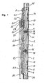
- Fig. 7 one according to the line VII-VII in the Fig. 3 guided longitudinal section through a part of the locking device according to Figure 4 in a free position in the front view, with three recesses in the web of the tooth comb with three inlet openings
- Fig. 8 one according to the line VIII-VIII in the Fig. 5 guided cross section through the locking device
- Fig. 9 one after the line IX-IX in the Fig. 4 guided cross section through the locking device
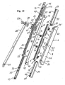
- Fig. 10 an axonometric view of the exploded locking device according to the first embodiment
- Fig. 10 an axonometric view of the exploded locking device according to the first embodiment
- Fig. 11 a partial cross section through the locking device in the first phase of mounting the protective channel with the protective strip in the front view
- Fig. 12 a partial view of the locking device according to Fig. 11 in a plan view
- Fig. 13 a partial cross section through the locking device in the second phase of the mounting of the protective channel with the protective strip in the front view
- Fig. 14 a plan view of a part of the locking device according to Fig. 13
- Fig. 15 a vertical section through the window frame with a swung-out window leaf in side view according to the second embodiment
- Fig. 16 one after the line XVI-XVI in Fig. 15 guided partial cross section through the window panel with a built-in locking device, on an enlarged scale
- Fig. 16 one after the line XVI-XVI in Fig. 15 guided partial cross section through the window panel with a built-in locking device, on an enlarged scale
- FIG. 17 a partial view of the, according to the window sheet Fig. 15 excluded locking device in a side view
- Fig. 18 a side view of the locking device according to Fig. 17
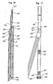
- Fig. 19 a partial front view of the recessed from the window sheet locking device according to Fig. 15 with the strut in the position for a closed window leaf
- Fig. 20 one after the line XX-XX in Fig. 19 guided longitudinal section through a part of the locking device
- Fig. 21 one after the line XXI-XXI in the Fig. 19 guided longitudinal section through a part of the locking device in a free position
- Fig. 22 one according to the line XXII-XXII in the Fig.
- Fig. 21 guided cross-section through a part of the locking device according to Figure 19 in a free position
- Fig. 23 a partial front view of the recessed from the window sheet locking device according to Fig. 15 with the strut in the position for a closed window leaf and the line of the cut being guided differently
- Fig. 24 a partial front view of the from the window leaf excluded locking device according to Fig. 15 with the strut in the position for a closed window leaf and the tooth slide being pushed for the sake of clarity of the illustrated section
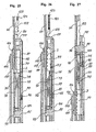
- Fig. 25 a guided according to the line XXV-XXV longitudinal section through a part of the locking device according to Fig. 23 in a free position, on an enlarged scale and in front view
- Fig. 25 a guided according to the line XXV-XXV longitudinal section through a part of the locking device according to Fig. 23 in a free position, on an enlarged scale and in front view
- Fig. 26 a guided according to the line XXV-XXV longitudinal section through a part of the locking device according to Fig. 23 in a secured position, on an enlarged scale and in front view
- Fig. 27 a guided according to the line XXVII-XXVII longitudinal section through a part of the locking device according to Fig. 24 in a secured position, on an enlarged scale and in front view
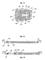
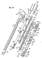
- Fig. 28 an axonometric view of the exploded locking device according to the second embodiment
- Fig. 29 an axonometric view from below of the modified headed bolt modified for assembly
- Fig. 30 an axonometric view from above of the modified head bolt according to Fig. 29, Fig. 31 a view from below of the modified toothed slide
- Fig. 29 an axonometric view from below of the modified headed bolt modified for assembly
- Fig. 30 an axonometric view from above of the modified head bolt according to Fig. 29, Fig. 31 a view
- Fig. 32 a view from below of the modified head bolt according to Fig. 30, Fig. 33 a bottom view of the end portion of the modified strut with a modified support opening, Fig. 34 an axonometric view of a part of the modified embodiment of the locking device in the first step of the assembly, Fig. 35 one of the illustration in Fig. 34 corresponding view, but in the second step of the assembly, Fig. 36 one of the illustration in Fig. 34 corresponding view, however, in the third step of the assembly, while the modified strut is pivoted on the modified head bolt for manual coupling to the connection element on the frame of the window sheet, and Fig. 37 one along the line XXXVII - XXXVII in Fig. 36 guided partial section through the locking device with the modified components for assembly.
- the first embodiment of the locking device for window, door, and the like consists of a toothed comb 2 ( Fig. 10 ) in the shape of the letter U, whose two legs are provided at the ends with transversely arranged teeth 3 .
- This tooth comb 2 is provided on its web 4 with three spaced depressions 5 , 6, 7 and is inserted into a protective channel 8 with a bottom 9 , which is provided with three inlet openings 10 , 11 , 12 ( FIG . Fig. 7 ) is provided for the introduction of the recesses 5, 6 , 7 of the web 4 of the tooth comb 2 .
- At least two compression spring 13 , 14 are arranged between the bottom 9 of the protective channel 8 and the web 4 of the toothed comb 2 .
- An adjustable traction means 15 in the form of an inverted letter U is slidably disposed between the legs of the toothed comb 2 and provided with a pair of shafts 16 , 17 transversely disposed in the central region, to which the rollers 18, 19 for moving the adjustable traction means 15 the web 4 of the tooth comb 2 and its recesses 5 , 6 , 7 are rotatably mounted.
- the shafts 16, 17 with the rollers 18 , 19 may, for. B. be replaced by sliding projections, not shown. This arrangement is achieved by means of a protective strip 20 (FIG. Fig.
- the toothed slide 32 has the shape of an inverted letter U, the two legs at the ends with transverse mating teeth 33 for engagement with the teeth 3 of Tooth comb 2 are provided. Therefore, the protective strip 20 forms in the engagement a support for the toothed slide 32 against the action of the compression spring 13 , 14 ,
- Hook-shaped holder 42 , 43 for coupling the Betquestioned Trents Komffenschs 44 by means of its transverse opening 45 are arranged at both ends of the adjustable traction means 15 .
- the actuating cable 44 is provided with a longitudinal groove 46 through which a spacer nose 47 for establishing the necessary clearance between the protective strip 20 and the guide lug 35 , as well as a next to the spacer nose 47, located near the end of the guide projection rivet projection 68 pass through.
- the same spacer nose 48 and the same rivet projection 67 are arranged on the opposite guide projection 34 .
- the protective strip 20 is connected to the protective channel 8 by means of three pairs of elongated holes 61, 62 63 in the protective strip 20 , and by means of three pairs of mounting projections 53, 54, 55 (FIG. Fig. 10 ), these being from the upper ones Edges of the side walls 56, 57 of the protective channel 8 protrude and pairs of mounting holes 58, 59, 60 include.
- adjustable traction means 15 with a placed on the hook-shaped holder 43 Betsch Trentitz 44 inserted between the webs of the tooth comb 2 .
- This actuating means 44 is placed with its longitudinal groove 46 on the spacer nose 47 and on the rivet projection 68 on the guide lug.
- the protective strip 20, to which the strut 30 and the toothed slider 32 has been connected to the spring washer 29 and the slider 26 by means of the head pin 28 is then placed on the protective groove 8 .
- the mounting projections 53, 54, 55 of the protective channel 8 are introduced during the placement of the protective strip 20 in the slots 61, 62 63 of the protective strip 20 , then the fastening projections 64, 65, 66 ( FIG. Fig. 11 ) pressed on the protective strip 20 under the force on the same both sides in the mounting holes 58, 59 , 60 of the protective channel 8 and the rivet projections 67 , 68 ( Fig. 10 ), which are arranged on the ends of the guide lugs 34, 35 and which engage in the rivet openings 69, 70 of the protective strip 20 , are riveted.
- the guide groove 21 in the protective strip 20 is provided on both ends with support edges 22, 23 and the adjustable traction means 15 is provided at both ends with hook-shaped holders 42 , 43 , so that the Betuschistszugstoff 44 with the transverse opening 45 on the corresponding hook-shaped holder 42nd , 43 can be put on.
- the protective strip 20 is made sufficiently long so that they can be tailored for mounting in the mounting groove 71 in the sheet 1 only to the required length and then protect all subsequent fittings.
- the control lever 49 is rotated, whereby, for example, the pinion is not shown and the Betschistszugstoff 44 and the adjustable traction means 15 are moved by means of a comb, not shown oblong from the secured position of the sheet 1 in the unlocked position , in that the rollers 18, 19 as a result of the elongated displacement of the adjustable traction means 15 from the position are rolled, in which they were in contact with the recesses 5, 6 of the web 4 of the tooth comb 2 , in the position in which they come into contact with the higher-mounted web 4 of the tooth comb 2 .
- the head bolt 28 is pushed in the guide groove 21 as needed to the maximum opening of the sheet, where the bolt abuts the support edge 22 , which closes the guide groove 21 of the protective strip 20 .
- the control lever 49 is rotated back, wherein the Betchanists Komstoff 44 is pushed back and the adjustable traction means 15 is moved back to its original position.
- the adjustable traction means 15 between the side walls of the tooth comb 2 and with the chutes 40 , 41 in the guide grooves 38 , 39 of the guide lugs 34 35 is pushed.
- An adjustable traction means 90 in the form of an inverted letter U is slidably disposed between the legs 76, 77 of the tooth comb 75 and provided with a pair of overhang projections 92, 93 on the web 91 for contact with the gentle elevations 79, 80 on the web 79, 80 of the tooth comb 75 provided.
- This arrangement is covered by a protective strip 94 , which rests on at least one contact surface 96 of the guide projection 85 .
- a rivet projection 99 is disposed on at least one guide projection 85 .
- the guide projections 84 , 85 , 86 are further provided with at least one mounting hole 104 which passes through the support bar 87 and which is arranged coaxially with at least one mounting opening 105 in the protective strip 94 , wherein the mounting opening 105 for at least one fastening screw, not shown, for screwing into the Sheet 1 is determined.
- the adjustable traction means 90 is thereby placed with its longitudinal openings 114, 115 on two guide projections 84 , 85 , in such a way that the cooperating gentle elevations 79, 80 of the tooth comb and the overhang projections 92 , 93 of the adjustable traction means 90 engage with each other the toothed slider 106 is opposite the toothed ridge 75 in the unlocked position.
- the connected by means of the connecting bolt 109 to the strut 111 tooth slide 106 is then mounted on the protective strip 94 and the whole assembly group is mounted with the protective strip 94 on the contact surfaces 95 , 96 , 97 on the guide projections 84 , 85 , 86 .
- the rivet projections 98, 99 , 100 penetrate into the rivet openings 101, 102, 103 in the protective strip 94 and they are then riveted.
Landscapes
- Engineering & Computer Science (AREA)
- Mechanical Engineering (AREA)
- Burglar Alarm Systems (AREA)
- Operating, Guiding And Securing Of Roll- Type Closing Members (AREA)
- Push-Button Switches (AREA)
- Lock And Its Accessories (AREA)
- Packaging For Recording Disks (AREA)
- Wing Frames And Configurations (AREA)
Priority Applications (2)
| Application Number | Priority Date | Filing Date | Title |
|---|---|---|---|
| PL08009439T PL1997990T3 (pl) | 2007-05-28 | 2008-05-23 | Uszczelniacz do drzwi i tym podobnych |
| SI200830108T SI1997990T1 (sl) | 2007-05-28 | 2008-05-23 | Naprava za zaklepanje oken, vrat in podobno |
Applications Claiming Priority (2)
| Application Number | Priority Date | Filing Date | Title |
|---|---|---|---|
| CZ20070366A CZ2007366A3 (cs) | 2007-05-28 | 2007-05-28 | Zajištovací ústrojí pro okna, dvere a podobne |
| CZ20080196A CZ2008196A3 (cs) | 2008-03-28 | 2008-03-28 | Zajištovací ústrojí pro okna, dvere a podobne |
Publications (2)
| Publication Number | Publication Date |
|---|---|
| EP1997990A1 EP1997990A1 (de) | 2008-12-03 |
| EP1997990B1 true EP1997990B1 (de) | 2010-10-20 |
Family
ID=39712233
Family Applications (1)
| Application Number | Title | Priority Date | Filing Date |
|---|---|---|---|
| EP08009439A Active EP1997990B1 (de) | 2007-05-28 | 2008-05-23 | Feststellvorrichtung für Fenster, Türe und Ähnliches |
Country Status (5)
| Country | Link |
|---|---|
| EP (1) | EP1997990B1 (pl) |
| AT (1) | ATE485432T1 (pl) |
| DE (1) | DE502008001561D1 (pl) |
| PL (1) | PL1997990T3 (pl) |
| SI (1) | SI1997990T1 (pl) |
Families Citing this family (3)
| Publication number | Priority date | Publication date | Assignee | Title |
|---|---|---|---|---|
| FR2960014B1 (fr) * | 2010-05-12 | 2012-06-29 | Assly | Ensemble pour baie |
| RS59234B1 (sr) * | 2014-04-04 | 2019-10-31 | Fapim S P A | Uređaj za otvaranje/zatvaranje prozora sa elementom za zaustavljanje krila prozora u otvorenom položaju |
| DE102016210986A1 (de) * | 2016-06-20 | 2017-10-26 | Geze Gmbh | Vorrichtung zum Feststellen eines Tür- oder Fensterflügels |
Family Cites Families (4)
| Publication number | Priority date | Publication date | Assignee | Title |
|---|---|---|---|---|
| CH377679A (de) * | 1959-09-18 | 1964-05-15 | Eltreva Ag | Fensterflügel-Feststellvorrichtung |
| DE2451556A1 (de) * | 1974-10-30 | 1976-05-06 | Siegenia Frank Kg | Feststellvorrichtung zur oeffnungsbegrenzung von kipp- und klappfluegeln, insbesondere kipp-schwenkfluegeln, an fenstern, tueren o.dgl. |
| DE19516588C1 (de) | 1995-05-05 | 1996-09-19 | Weidtmann Wilhelm Kg | Feststellvorrichtung für Fenster, Türen od. dgl. |
| DE20112136U1 (de) * | 2001-07-21 | 2002-06-06 | CEDOS Engineering GmbH, 44388 Dortmund | Vorrichtung zum Festsetzen von mit einem Dreh/Kippbeschlag ausgerüsteten Fenster- oder Türflügeln |
-
2008
- 2008-05-23 PL PL08009439T patent/PL1997990T3/pl unknown
- 2008-05-23 SI SI200830108T patent/SI1997990T1/sl unknown
- 2008-05-23 DE DE502008001561T patent/DE502008001561D1/de active Active
- 2008-05-23 AT AT08009439T patent/ATE485432T1/de active
- 2008-05-23 EP EP08009439A patent/EP1997990B1/de active Active
Also Published As
| Publication number | Publication date |
|---|---|
| DE502008001561D1 (de) | 2010-12-02 |
| ATE485432T1 (de) | 2010-11-15 |
| SI1997990T1 (sl) | 2011-01-31 |
| EP1997990A1 (de) | 2008-12-03 |
| PL1997990T3 (pl) | 2011-04-29 |
Similar Documents
| Publication | Publication Date | Title |
|---|---|---|
| DE3103352C2 (de) | Pinzetten- oder zangenförmiges chirurgisches Instrument | |
| EP1727954B1 (de) | Scharnier, insbesondere zum verbinden zweier teilklappen einer faltklappe | |
| EP1632151B1 (de) | Schubladenzarge | |
| AT408470B (de) | Möbelscharnier | |
| EP1972743B1 (de) | Schliessteil | |
| DE102011011113B4 (de) | Rahmensystem eines Partikelschutzgitters | |
| DE3408124A1 (de) | Verschluss fuer sportschuhe, insbesondere skischuhe oder bergschuhe | |
| WO2017216376A1 (de) | Flügelanordnung und verfahren zur frontalmontage eines beschlagteils in einer solchen flügelanordnung | |
| EP1997990B1 (de) | Feststellvorrichtung für Fenster, Türe und Ähnliches | |
| EP2951374B1 (de) | Laufteil zum führen eines möbelteils in einer führungsrichtung über eine führungsschiene und möbelbeschlag | |
| DE2653106C2 (de) | Klappenhalter | |
| EP2328439A1 (de) | Möbelauszugsführung | |
| AT1732U1 (de) | Scharnier | |
| EP3183408B1 (de) | Steuerelement für eine beschlaganordnung | |
| EP1470951B1 (de) | Ratschenartige Verstellvorrichtung | |
| DE102007029519B4 (de) | Keilsteller mit verbesserter Umlenkung | |
| DE102006039025A1 (de) | Führungsbeschlag eines Schiebetürbeschlags | |
| DE3913319C2 (pl) | ||
| DE102007010209B4 (de) | Antriebsvorrichtung | |
| DE2423436A1 (de) | Scharnier | |
| EP0199270A2 (de) | Feststellvorrichtung für einen Fenster- oder Türflügel in wenigstens einer Spaltlüftungsstellung | |
| DE3205417C2 (de) | Dachfenster für Kraftfahrzeuge | |
| DE102011003371A1 (de) | Verriegelungsanordnung für Fenster, Türen oder dergleichen mit einem Schwenkriegel | |
| EP4124709B1 (de) | Führungsprofil für eine auszugssperre, auszugssperre, möbel und verfahren zur bestückung eines führungsprofils | |
| DE202007000136U1 (de) | Jalousie |
Legal Events
| Date | Code | Title | Description |
|---|---|---|---|
| PUAI | Public reference made under article 153(3) epc to a published international application that has entered the european phase |
Free format text: ORIGINAL CODE: 0009012 |
|
| AK | Designated contracting states |
Kind code of ref document: A1 Designated state(s): AT BE BG CH CY CZ DE DK EE ES FI FR GB GR HR HU IE IS IT LI LT LU LV MC MT NL NO PL PT RO SE SI SK TR |
|
| AX | Request for extension of the european patent |
Extension state: AL BA MK RS |
|
| 17P | Request for examination filed |
Effective date: 20090410 |
|
| AKX | Designation fees paid |
Designated state(s): AT BE BG CH CY CZ DE DK EE ES FI FR GB GR HR HU IE IS IT LI LT LU LV MC MT NL NO PL PT RO SE SI SK TR |
|
| GRAP | Despatch of communication of intention to grant a patent |
Free format text: ORIGINAL CODE: EPIDOSNIGR1 |
|
| GRAS | Grant fee paid |
Free format text: ORIGINAL CODE: EPIDOSNIGR3 |
|
| GRAA | (expected) grant |
Free format text: ORIGINAL CODE: 0009210 |
|
| AK | Designated contracting states |
Kind code of ref document: B1 Designated state(s): AT BE BG CH CY CZ DE DK EE ES FI FR GB GR HR HU IE IS IT LI LT LU LV MC MT NL NO PL PT RO SE SI SK TR |
|
| REG | Reference to a national code |
Ref country code: GB Ref legal event code: FG4D Free format text: NOT ENGLISH |
|
| REG | Reference to a national code |
Ref country code: CH Ref legal event code: EP |
|
| REG | Reference to a national code |
Ref country code: IE Ref legal event code: FG4D Free format text: LANGUAGE OF EP DOCUMENT: GERMAN |
|
| REF | Corresponds to: |
Ref document number: 502008001561 Country of ref document: DE Date of ref document: 20101202 Kind code of ref document: P |
|
| REG | Reference to a national code |
Ref country code: NL Ref legal event code: VDEP Effective date: 20101020 |
|
| LTIE | Lt: invalidation of european patent or patent extension |
Effective date: 20101020 |
|
| PG25 | Lapsed in a contracting state [announced via postgrant information from national office to epo] |
Ref country code: NO Free format text: LAPSE BECAUSE OF FAILURE TO SUBMIT A TRANSLATION OF THE DESCRIPTION OR TO PAY THE FEE WITHIN THE PRESCRIBED TIME-LIMIT Effective date: 20110120 Ref country code: LT Free format text: LAPSE BECAUSE OF FAILURE TO SUBMIT A TRANSLATION OF THE DESCRIPTION OR TO PAY THE FEE WITHIN THE PRESCRIBED TIME-LIMIT Effective date: 20101020 |
|
| REG | Reference to a national code |
Ref country code: PL Ref legal event code: T3 |
|
| REG | Reference to a national code |
Ref country code: IE Ref legal event code: FD4D |
|
| REG | Reference to a national code |
Ref country code: HU Ref legal event code: AG4A Ref document number: E010158 Country of ref document: HU |
|
| PG25 | Lapsed in a contracting state [announced via postgrant information from national office to epo] |
Ref country code: SE Free format text: LAPSE BECAUSE OF FAILURE TO SUBMIT A TRANSLATION OF THE DESCRIPTION OR TO PAY THE FEE WITHIN THE PRESCRIBED TIME-LIMIT Effective date: 20101020 Ref country code: PT Free format text: LAPSE BECAUSE OF FAILURE TO SUBMIT A TRANSLATION OF THE DESCRIPTION OR TO PAY THE FEE WITHIN THE PRESCRIBED TIME-LIMIT Effective date: 20110221 Ref country code: IS Free format text: LAPSE BECAUSE OF FAILURE TO SUBMIT A TRANSLATION OF THE DESCRIPTION OR TO PAY THE FEE WITHIN THE PRESCRIBED TIME-LIMIT Effective date: 20110220 Ref country code: HR Free format text: LAPSE BECAUSE OF FAILURE TO SUBMIT A TRANSLATION OF THE DESCRIPTION OR TO PAY THE FEE WITHIN THE PRESCRIBED TIME-LIMIT Effective date: 20101020 Ref country code: FI Free format text: LAPSE BECAUSE OF FAILURE TO SUBMIT A TRANSLATION OF THE DESCRIPTION OR TO PAY THE FEE WITHIN THE PRESCRIBED TIME-LIMIT Effective date: 20101020 Ref country code: NL Free format text: LAPSE BECAUSE OF FAILURE TO SUBMIT A TRANSLATION OF THE DESCRIPTION OR TO PAY THE FEE WITHIN THE PRESCRIBED TIME-LIMIT Effective date: 20101020 Ref country code: LV Free format text: LAPSE BECAUSE OF FAILURE TO SUBMIT A TRANSLATION OF THE DESCRIPTION OR TO PAY THE FEE WITHIN THE PRESCRIBED TIME-LIMIT Effective date: 20101020 Ref country code: BG Free format text: LAPSE BECAUSE OF FAILURE TO SUBMIT A TRANSLATION OF THE DESCRIPTION OR TO PAY THE FEE WITHIN THE PRESCRIBED TIME-LIMIT Effective date: 20110120 |
|
| PG25 | Lapsed in a contracting state [announced via postgrant information from national office to epo] |
Ref country code: GR Free format text: LAPSE BECAUSE OF FAILURE TO SUBMIT A TRANSLATION OF THE DESCRIPTION OR TO PAY THE FEE WITHIN THE PRESCRIBED TIME-LIMIT Effective date: 20110121 |
|
| PG25 | Lapsed in a contracting state [announced via postgrant information from national office to epo] |
Ref country code: IE Free format text: LAPSE BECAUSE OF FAILURE TO SUBMIT A TRANSLATION OF THE DESCRIPTION OR TO PAY THE FEE WITHIN THE PRESCRIBED TIME-LIMIT Effective date: 20101020 Ref country code: EE Free format text: LAPSE BECAUSE OF FAILURE TO SUBMIT A TRANSLATION OF THE DESCRIPTION OR TO PAY THE FEE WITHIN THE PRESCRIBED TIME-LIMIT Effective date: 20101020 Ref country code: ES Free format text: LAPSE BECAUSE OF FAILURE TO SUBMIT A TRANSLATION OF THE DESCRIPTION OR TO PAY THE FEE WITHIN THE PRESCRIBED TIME-LIMIT Effective date: 20110131 |
|
| PLBE | No opposition filed within time limit |
Free format text: ORIGINAL CODE: 0009261 |
|
| STAA | Information on the status of an ep patent application or granted ep patent |
Free format text: STATUS: NO OPPOSITION FILED WITHIN TIME LIMIT |
|
| PG25 | Lapsed in a contracting state [announced via postgrant information from national office to epo] |
Ref country code: DK Free format text: LAPSE BECAUSE OF FAILURE TO SUBMIT A TRANSLATION OF THE DESCRIPTION OR TO PAY THE FEE WITHIN THE PRESCRIBED TIME-LIMIT Effective date: 20101020 Ref country code: SK Free format text: LAPSE BECAUSE OF FAILURE TO SUBMIT A TRANSLATION OF THE DESCRIPTION OR TO PAY THE FEE WITHIN THE PRESCRIBED TIME-LIMIT Effective date: 20101020 Ref country code: RO Free format text: LAPSE BECAUSE OF FAILURE TO SUBMIT A TRANSLATION OF THE DESCRIPTION OR TO PAY THE FEE WITHIN THE PRESCRIBED TIME-LIMIT Effective date: 20101020 |
|
| 26N | No opposition filed |
Effective date: 20110721 |
|
| REG | Reference to a national code |
Ref country code: DE Ref legal event code: R097 Ref document number: 502008001561 Country of ref document: DE Effective date: 20110721 |
|
| BERE | Be: lapsed |
Owner name: TOKOZ A.S. Effective date: 20110531 |
|
| PG25 | Lapsed in a contracting state [announced via postgrant information from national office to epo] |
Ref country code: MC Free format text: LAPSE BECAUSE OF NON-PAYMENT OF DUE FEES Effective date: 20110531 Ref country code: MT Free format text: LAPSE BECAUSE OF FAILURE TO SUBMIT A TRANSLATION OF THE DESCRIPTION OR TO PAY THE FEE WITHIN THE PRESCRIBED TIME-LIMIT Effective date: 20101020 Ref country code: IT Free format text: LAPSE BECAUSE OF FAILURE TO SUBMIT A TRANSLATION OF THE DESCRIPTION OR TO PAY THE FEE WITHIN THE PRESCRIBED TIME-LIMIT Effective date: 20101020 |
|
| PG25 | Lapsed in a contracting state [announced via postgrant information from national office to epo] |
Ref country code: BE Free format text: LAPSE BECAUSE OF NON-PAYMENT OF DUE FEES Effective date: 20110531 |
|
| REG | Reference to a national code |
Ref country code: CH Ref legal event code: PL |
|
| PG25 | Lapsed in a contracting state [announced via postgrant information from national office to epo] |
Ref country code: CH Free format text: LAPSE BECAUSE OF NON-PAYMENT OF DUE FEES Effective date: 20120531 Ref country code: LI Free format text: LAPSE BECAUSE OF NON-PAYMENT OF DUE FEES Effective date: 20120531 |
|
| PG25 | Lapsed in a contracting state [announced via postgrant information from national office to epo] |
Ref country code: LU Free format text: LAPSE BECAUSE OF NON-PAYMENT OF DUE FEES Effective date: 20110523 Ref country code: CY Free format text: LAPSE BECAUSE OF FAILURE TO SUBMIT A TRANSLATION OF THE DESCRIPTION OR TO PAY THE FEE WITHIN THE PRESCRIBED TIME-LIMIT Effective date: 20101020 |
|
| PG25 | Lapsed in a contracting state [announced via postgrant information from national office to epo] |
Ref country code: TR Free format text: LAPSE BECAUSE OF FAILURE TO SUBMIT A TRANSLATION OF THE DESCRIPTION OR TO PAY THE FEE WITHIN THE PRESCRIBED TIME-LIMIT Effective date: 20101020 |
|
| PGFP | Annual fee paid to national office [announced via postgrant information from national office to epo] |
Ref country code: GB Payment date: 20140521 Year of fee payment: 7 |
|
| PGFP | Annual fee paid to national office [announced via postgrant information from national office to epo] |
Ref country code: PL Payment date: 20140424 Year of fee payment: 7 |
|
| GBPC | Gb: european patent ceased through non-payment of renewal fee |
Effective date: 20150523 |
|
| PG25 | Lapsed in a contracting state [announced via postgrant information from national office to epo] |
Ref country code: GB Free format text: LAPSE BECAUSE OF NON-PAYMENT OF DUE FEES Effective date: 20150523 |
|
| REG | Reference to a national code |
Ref country code: FR Ref legal event code: PLFP Year of fee payment: 9 |
|
| PG25 | Lapsed in a contracting state [announced via postgrant information from national office to epo] |
Ref country code: PL Free format text: LAPSE BECAUSE OF NON-PAYMENT OF DUE FEES Effective date: 20150523 |
|
| PGFP | Annual fee paid to national office [announced via postgrant information from national office to epo] |
Ref country code: FR Payment date: 20160520 Year of fee payment: 9 |
|
| REG | Reference to a national code |
Ref country code: FR Ref legal event code: ST Effective date: 20180131 |
|
| PG25 | Lapsed in a contracting state [announced via postgrant information from national office to epo] |
Ref country code: FR Free format text: LAPSE BECAUSE OF NON-PAYMENT OF DUE FEES Effective date: 20170531 |
|
| PGFP | Annual fee paid to national office [announced via postgrant information from national office to epo] |
Ref country code: SI Payment date: 20181112 Year of fee payment: 11 |
|
| PG25 | Lapsed in a contracting state [announced via postgrant information from national office to epo] |
Ref country code: SI Free format text: LAPSE BECAUSE OF NON-PAYMENT OF DUE FEES Effective date: 20190524 |
|
| P01 | Opt-out of the competence of the unified patent court (upc) registered |
Effective date: 20230325 |
|
| PGFP | Annual fee paid to national office [announced via postgrant information from national office to epo] |
Ref country code: AT Payment date: 20230522 Year of fee payment: 16 |
|
| PGFP | Annual fee paid to national office [announced via postgrant information from national office to epo] |
Ref country code: CZ Payment date: 20240219 Year of fee payment: 17 |
|
| PGFP | Annual fee paid to national office [announced via postgrant information from national office to epo] |
Ref country code: DE Payment date: 20240521 Year of fee payment: 17 |
|
| REG | Reference to a national code |
Ref country code: AT Ref legal event code: MM01 Ref document number: 485432 Country of ref document: AT Kind code of ref document: T Effective date: 20240523 |
|
| PG25 | Lapsed in a contracting state [announced via postgrant information from national office to epo] |
Ref country code: AT Free format text: LAPSE BECAUSE OF NON-PAYMENT OF DUE FEES Effective date: 20240523 |
|
| PG25 | Lapsed in a contracting state [announced via postgrant information from national office to epo] |
Ref country code: AT Free format text: LAPSE BECAUSE OF NON-PAYMENT OF DUE FEES Effective date: 20240523 |
|
| PGFP | Annual fee paid to national office [announced via postgrant information from national office to epo] |
Ref country code: HU Payment date: 20250523 Year of fee payment: 18 |
|
| REG | Reference to a national code |
Ref country code: DE Ref legal event code: R119 Ref document number: 502008001561 Country of ref document: DE |
|
| PG25 | Lapsed in a contracting state [announced via postgrant information from national office to epo] |
Ref country code: CZ Free format text: LAPSE BECAUSE OF NON-PAYMENT OF DUE FEES Effective date: 20250523 |