EP1997990B1 - Check device for windows, doors and the like - Google Patents
Check device for windows, doors and the like Download PDFInfo
- Publication number
- EP1997990B1 EP1997990B1 EP08009439A EP08009439A EP1997990B1 EP 1997990 B1 EP1997990 B1 EP 1997990B1 EP 08009439 A EP08009439 A EP 08009439A EP 08009439 A EP08009439 A EP 08009439A EP 1997990 B1 EP1997990 B1 EP 1997990B1
- Authority
- EP
- European Patent Office
- Prior art keywords
- locking device
- toothed
- slider
- toothed rack
- guide
- Prior art date
- Legal status (The legal status is an assumption and is not a legal conclusion. Google has not performed a legal analysis and makes no representation as to the accuracy of the status listed.)
- Active
Links
Images


Classifications
-
- E—FIXED CONSTRUCTIONS
- E05—LOCKS; KEYS; WINDOW OR DOOR FITTINGS; SAFES
- E05C—BOLTS OR FASTENING DEVICES FOR WINGS, SPECIALLY FOR DOORS OR WINDOWS
- E05C17/00—Devices for holding wings open; Devices for limiting opening of wings or for holding wings open by a movable member extending between frame and wing; Braking devices, stops or buffers, combined therewith
- E05C17/02—Devices for holding wings open; Devices for limiting opening of wings or for holding wings open by a movable member extending between frame and wing; Braking devices, stops or buffers, combined therewith by mechanical means
- E05C17/04—Devices for holding wings open; Devices for limiting opening of wings or for holding wings open by a movable member extending between frame and wing; Braking devices, stops or buffers, combined therewith by mechanical means with a movable bar or equivalent member extending between frame and wing
- E05C17/12—Devices for holding wings open; Devices for limiting opening of wings or for holding wings open by a movable member extending between frame and wing; Braking devices, stops or buffers, combined therewith by mechanical means with a movable bar or equivalent member extending between frame and wing consisting of a single rod
- E05C17/24—Devices for holding wings open; Devices for limiting opening of wings or for holding wings open by a movable member extending between frame and wing; Braking devices, stops or buffers, combined therewith by mechanical means with a movable bar or equivalent member extending between frame and wing consisting of a single rod pivoted at one end, and with the other end running along a guide member
- E05C17/28—Devices for holding wings open; Devices for limiting opening of wings or for holding wings open by a movable member extending between frame and wing; Braking devices, stops or buffers, combined therewith by mechanical means with a movable bar or equivalent member extending between frame and wing consisting of a single rod pivoted at one end, and with the other end running along a guide member with braking, clamping or securing means at the connection to the guide member
-
- E—FIXED CONSTRUCTIONS
- E05—LOCKS; KEYS; WINDOW OR DOOR FITTINGS; SAFES
- E05B—LOCKS; ACCESSORIES THEREFOR; HANDCUFFS
- E05B63/00—Locks or fastenings with special structural characteristics
- E05B63/04—Locks or fastenings with special structural characteristics for alternative use on the right-hand or left-hand side of wings
Definitions
- a device for detecting a window or door leaf in the desired position is the patent, for example DE 19516588 refer to.
- This patent describes a locking device for windows, doors and the like with a fixed frame and a pivotally connected thereto sheet.
- the actual locking device is disposed in a lateral portion of the blade and includes a slidable rod having a handle at its free end.
- the main part of the displaceable rod is slidably mounted on the bottom of a guide strip whose section has the shape of the letter U and which is fixedly arranged in the sheet.
- a part of the displaceable rod is provided on the surface facing away from the bottom of the guide bar surface with spaced flat cams.
- a longitudinally fixed, transversely flexible movable rack rests with their counter cams on these flat cam and a portion of its length is provided with a cross-toothing for connection to a corresponding cross-toothing on a slider.
- the slider is mounted in the guide rail by means of two grooves, wherein guide projections, which are formed on the inner surface of the guide bar, engage in these grooves.
- One strut is to the slider at one Pins pivotally connected, whose other end is arranged in a stanchion attached to the frame swaying.
- One attachment piece is attached to each of the ends of the bottom of the guide rail.
- Each of the extensions forms an end stop for delimiting the longitudinal movement of the slider, as well as an upper support for the rack.
- a spring for pressing the rack on the sliding rod is arranged in each of the attachments.
- a disadvantage of the device consists in the fact that the functional components of the device are arranged so that in the case of an adaptation of the dimensions of the entire device to the normal size of the groove for the fitting structure remains a relatively small amount for the teeth of the slider and the rack , As a result of the small teeth, the holding force acting between the slider and the toothed bar is relatively low. In order to secure a sufficient holding force between the slider and the rack, the slider must be relatively long. As a result of the low holding force between the slider and the rack must be the point of application of the holding force as far as possible from the hinges, especially in the case of larger leaves, so a relatively long strut must be used to connect the slider with the window frame.
- the tooth comb is superimposed together with the adjustable traction means and the support bar by means of the protective strip, wherein the protective strip is provided with at least one attachment opening for a wood screws for connection to the sheet.
- the adjustable traction means may be provided at its ends with hook-shaped holders for connecting a Betuschistszugstoffs, possibly the adjustable traction means may be provided in the end region with a transverse groove for connecting a Betreli whyszugstoffs means of its crosspiece.
- the protective channel may be provided at its ends with guide lugs with guide grooves in the shape of the letter T for guiding slides formed at the ends of the adjustable traction means and for guiding the engaging Betreli Trents Komffens, or the support bar end caps have, which on their side walls with flexible Holders are provided for a trituration with a mounting groove in the sheet.
- the guide lugs are provided near their ends with rivet projections for their connection to the protective strip.
- the advantage of the locking device according to the invention is that the arrangement of the components allows a greater height of the teeth on the tooth comb and the tooth slide, so that the entire locking device in comparison to the locking device according to DE 19516588 can exert a greater force to hold the window or door leaf or similar sheet in a relatively shorter slide. As a result of this greater force, it is not necessary to shift the force action point far from the hinges, so that the applications of a size of the locking device for leaves of different sizes are wider.
- Another advantage of a preferred embodiment of the invention according to claim 16 is that a machine assembly is possible.
- Fig. 1 a vertical section through the window frame with a swung-out window leaf in side view according to the first embodiment
- Fig. 2 one after the line II-II in Fig. 1 Guided partial section through the window panel with a built-in locking device, on an enlarged scale
- Fig. 3 a partial view of the, excluded from the window leaf locking device in a side view
- Fig. 4 a front view of the locking device according to Fig. 3
- Fig. 5 a guided along the line VV longitudinal section through a part of the locking device according to Fig. 4 in a free position, on an enlarged scale and with inserted sections
- Fig. 5 a guided along the line VV longitudinal section through a part of the locking device according to Fig. 4 in a free position, on an enlarged scale and with inserted sections
- Fig. 5 a guided along the line VV longitudinal section through a part of the locking device according to Fig. 4 in a free position, on an enlarged scale and with inserted
- Fig. 6 a guided along the line VV longitudinal section through a part of the locking device according to Fig. 4 in a secured position, also on an enlarged scale and with inserted sections
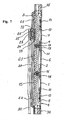
- Fig. 7 one according to the line VII-VII in the Fig. 3 guided longitudinal section through a part of the locking device according to Figure 4 in a free position in the front view, with three recesses in the web of the tooth comb with three inlet openings
- Fig. 8 one according to the line VIII-VIII in the Fig. 5 guided cross section through the locking device
- Fig. 9 one after the line IX-IX in the Fig. 4 guided cross section through the locking device
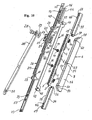
- Fig. 10 an axonometric view of the exploded locking device according to the first embodiment
- Fig. 10 an axonometric view of the exploded locking device according to the first embodiment
- Fig. 11 a partial cross section through the locking device in the first phase of mounting the protective channel with the protective strip in the front view
- Fig. 12 a partial view of the locking device according to Fig. 11 in a plan view
- Fig. 13 a partial cross section through the locking device in the second phase of the mounting of the protective channel with the protective strip in the front view
- Fig. 14 a plan view of a part of the locking device according to Fig. 13
- Fig. 15 a vertical section through the window frame with a swung-out window leaf in side view according to the second embodiment
- Fig. 16 one after the line XVI-XVI in Fig. 15 guided partial cross section through the window panel with a built-in locking device, on an enlarged scale
- Fig. 16 one after the line XVI-XVI in Fig. 15 guided partial cross section through the window panel with a built-in locking device, on an enlarged scale
- FIG. 17 a partial view of the, according to the window sheet Fig. 15 excluded locking device in a side view
- Fig. 18 a side view of the locking device according to Fig. 17
- Fig. 19 a partial front view of the recessed from the window sheet locking device according to Fig. 15 with the strut in the position for a closed window leaf
- Fig. 20 one after the line XX-XX in Fig. 19 guided longitudinal section through a part of the locking device
- Fig. 21 one after the line XXI-XXI in the Fig. 19 guided longitudinal section through a part of the locking device in a free position
- Fig. 22 one according to the line XXII-XXII in the Fig.
- Fig. 21 guided cross-section through a part of the locking device according to Figure 19 in a free position
- Fig. 23 a partial front view of the recessed from the window sheet locking device according to Fig. 15 with the strut in the position for a closed window leaf and the line of the cut being guided differently
- Fig. 24 a partial front view of the from the window leaf excluded locking device according to Fig. 15 with the strut in the position for a closed window leaf and the tooth slide being pushed for the sake of clarity of the illustrated section
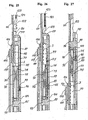
- Fig. 25 a guided according to the line XXV-XXV longitudinal section through a part of the locking device according to Fig. 23 in a free position, on an enlarged scale and in front view
- Fig. 25 a guided according to the line XXV-XXV longitudinal section through a part of the locking device according to Fig. 23 in a free position, on an enlarged scale and in front view
- Fig. 26 a guided according to the line XXV-XXV longitudinal section through a part of the locking device according to Fig. 23 in a secured position, on an enlarged scale and in front view
- Fig. 27 a guided according to the line XXVII-XXVII longitudinal section through a part of the locking device according to Fig. 24 in a secured position, on an enlarged scale and in front view
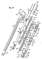
- Fig. 28 an axonometric view of the exploded locking device according to the second embodiment
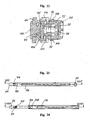
- Fig. 29 an axonometric view from below of the modified headed bolt modified for assembly
- Fig. 30 an axonometric view from above of the modified head bolt according to Fig. 29, Fig. 31 a view from below of the modified toothed slide
- Fig. 29 an axonometric view from below of the modified headed bolt modified for assembly
- Fig. 30 an axonometric view from above of the modified head bolt according to Fig. 29, Fig. 31 a view
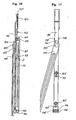
- Fig. 32 a view from below of the modified head bolt according to Fig. 30, Fig. 33 a bottom view of the end portion of the modified strut with a modified support opening, Fig. 34 an axonometric view of a part of the modified embodiment of the locking device in the first step of the assembly, Fig. 35 one of the illustration in Fig. 34 corresponding view, but in the second step of the assembly, Fig. 36 one of the illustration in Fig. 34 corresponding view, however, in the third step of the assembly, while the modified strut is pivoted on the modified head bolt for manual coupling to the connection element on the frame of the window sheet, and Fig. 37 one along the line XXXVII - XXXVII in Fig. 36 guided partial section through the locking device with the modified components for assembly.
- the first embodiment of the locking device for window, door, and the like consists of a toothed comb 2 ( Fig. 10 ) in the shape of the letter U, whose two legs are provided at the ends with transversely arranged teeth 3 .
- This tooth comb 2 is provided on its web 4 with three spaced depressions 5 , 6, 7 and is inserted into a protective channel 8 with a bottom 9 , which is provided with three inlet openings 10 , 11 , 12 ( FIG . Fig. 7 ) is provided for the introduction of the recesses 5, 6 , 7 of the web 4 of the tooth comb 2 .
- At least two compression spring 13 , 14 are arranged between the bottom 9 of the protective channel 8 and the web 4 of the toothed comb 2 .
- An adjustable traction means 15 in the form of an inverted letter U is slidably disposed between the legs of the toothed comb 2 and provided with a pair of shafts 16 , 17 transversely disposed in the central region, to which the rollers 18, 19 for moving the adjustable traction means 15 the web 4 of the tooth comb 2 and its recesses 5 , 6 , 7 are rotatably mounted.
- the shafts 16, 17 with the rollers 18 , 19 may, for. B. be replaced by sliding projections, not shown. This arrangement is achieved by means of a protective strip 20 (FIG. Fig.
- the toothed slide 32 has the shape of an inverted letter U, the two legs at the ends with transverse mating teeth 33 for engagement with the teeth 3 of Tooth comb 2 are provided. Therefore, the protective strip 20 forms in the engagement a support for the toothed slide 32 against the action of the compression spring 13 , 14 ,
- Hook-shaped holder 42 , 43 for coupling the Betquestioned Trents Komffenschs 44 by means of its transverse opening 45 are arranged at both ends of the adjustable traction means 15 .
- the actuating cable 44 is provided with a longitudinal groove 46 through which a spacer nose 47 for establishing the necessary clearance between the protective strip 20 and the guide lug 35 , as well as a next to the spacer nose 47, located near the end of the guide projection rivet projection 68 pass through.
- the same spacer nose 48 and the same rivet projection 67 are arranged on the opposite guide projection 34 .
- the protective strip 20 is connected to the protective channel 8 by means of three pairs of elongated holes 61, 62 63 in the protective strip 20 , and by means of three pairs of mounting projections 53, 54, 55 (FIG. Fig. 10 ), these being from the upper ones Edges of the side walls 56, 57 of the protective channel 8 protrude and pairs of mounting holes 58, 59, 60 include.
- adjustable traction means 15 with a placed on the hook-shaped holder 43 Betsch Trentitz 44 inserted between the webs of the tooth comb 2 .
- This actuating means 44 is placed with its longitudinal groove 46 on the spacer nose 47 and on the rivet projection 68 on the guide lug.
- the protective strip 20, to which the strut 30 and the toothed slider 32 has been connected to the spring washer 29 and the slider 26 by means of the head pin 28 is then placed on the protective groove 8 .
- the mounting projections 53, 54, 55 of the protective channel 8 are introduced during the placement of the protective strip 20 in the slots 61, 62 63 of the protective strip 20 , then the fastening projections 64, 65, 66 ( FIG. Fig. 11 ) pressed on the protective strip 20 under the force on the same both sides in the mounting holes 58, 59 , 60 of the protective channel 8 and the rivet projections 67 , 68 ( Fig. 10 ), which are arranged on the ends of the guide lugs 34, 35 and which engage in the rivet openings 69, 70 of the protective strip 20 , are riveted.
- the guide groove 21 in the protective strip 20 is provided on both ends with support edges 22, 23 and the adjustable traction means 15 is provided at both ends with hook-shaped holders 42 , 43 , so that the Betuschistszugstoff 44 with the transverse opening 45 on the corresponding hook-shaped holder 42nd , 43 can be put on.
- the protective strip 20 is made sufficiently long so that they can be tailored for mounting in the mounting groove 71 in the sheet 1 only to the required length and then protect all subsequent fittings.
- the control lever 49 is rotated, whereby, for example, the pinion is not shown and the Betschistszugstoff 44 and the adjustable traction means 15 are moved by means of a comb, not shown oblong from the secured position of the sheet 1 in the unlocked position , in that the rollers 18, 19 as a result of the elongated displacement of the adjustable traction means 15 from the position are rolled, in which they were in contact with the recesses 5, 6 of the web 4 of the tooth comb 2 , in the position in which they come into contact with the higher-mounted web 4 of the tooth comb 2 .
- the head bolt 28 is pushed in the guide groove 21 as needed to the maximum opening of the sheet, where the bolt abuts the support edge 22 , which closes the guide groove 21 of the protective strip 20 .
- the control lever 49 is rotated back, wherein the Betchanists Komstoff 44 is pushed back and the adjustable traction means 15 is moved back to its original position.
- the adjustable traction means 15 between the side walls of the tooth comb 2 and with the chutes 40 , 41 in the guide grooves 38 , 39 of the guide lugs 34 35 is pushed.
- An adjustable traction means 90 in the form of an inverted letter U is slidably disposed between the legs 76, 77 of the tooth comb 75 and provided with a pair of overhang projections 92, 93 on the web 91 for contact with the gentle elevations 79, 80 on the web 79, 80 of the tooth comb 75 provided.
- This arrangement is covered by a protective strip 94 , which rests on at least one contact surface 96 of the guide projection 85 .
- a rivet projection 99 is disposed on at least one guide projection 85 .
- the guide projections 84 , 85 , 86 are further provided with at least one mounting hole 104 which passes through the support bar 87 and which is arranged coaxially with at least one mounting opening 105 in the protective strip 94 , wherein the mounting opening 105 for at least one fastening screw, not shown, for screwing into the Sheet 1 is determined.
- the adjustable traction means 90 is thereby placed with its longitudinal openings 114, 115 on two guide projections 84 , 85 , in such a way that the cooperating gentle elevations 79, 80 of the tooth comb and the overhang projections 92 , 93 of the adjustable traction means 90 engage with each other the toothed slider 106 is opposite the toothed ridge 75 in the unlocked position.
- the connected by means of the connecting bolt 109 to the strut 111 tooth slide 106 is then mounted on the protective strip 94 and the whole assembly group is mounted with the protective strip 94 on the contact surfaces 95 , 96 , 97 on the guide projections 84 , 85 , 86 .
- the rivet projections 98, 99 , 100 penetrate into the rivet openings 101, 102, 103 in the protective strip 94 and they are then riveted.
Abstract
Description
Die Erfindung betrifft eine Feststellvorrichtung für Fenster, Türe und Ähnliches, mit einem festen Teil, insbesondere einem Rahmen, und mit einem beweglichen Teil, insbesondere einem Blatt, die einen Zahnkamm zum Eingreifen mit einem mit einer Strebe verbundenen Zahnschieber und ein in Längsrichtung verstellbares Zugmittel zur Höhenbetätigung in Querrichtung des Zahnkamms umfasst, wobei ein Ende der Strebe zusammen mit dem Zahnschieber auf einem Kopfbolzen schwenkbar angeordnet ist und das andere Ende der Strebe auf einem auf dem Rahmen des Fenster- oder Türblatts befestigbaren Anschlusselement schwenkbar angeordnet ist, wobei das verstellbare Zugmittel zusammen mit dem Zahnkamm mit zusammenwirkenden Mitteln zum Erreichen einer gesicherten und einer entsicherten Lage des Zahnschiebers versehen sind, während der Zahnkamm auf einem Tragelement in Querrichtung flexibel beweglich angeordnet ist.The invention relates to a locking device for windows, doors and the like, with a fixed part, in particular a frame, and with a movable part, in particular a sheet having a tooth comb for engagement with a connected to a strut tooth shifter and a longitudinally adjustable traction means for Heightwise operation in the transverse direction of the tooth comb comprises, wherein one end of the strut is pivotally mounted together with the tooth slide on a head bolt and the other end of the strut is pivotally mounted on a mountable on the frame of the window or door panel connection element, wherein the adjustable traction means together with the tooth comb are provided with cooperating means for achieving a secured and an unlocked position of the tooth slide, while the tooth comb is flexibly movably arranged on a support element in the transverse direction.
Eine Vorrichtung zum Feststellen eines Fenster- oder Türblatts in der gewünschten Lage ist z.B. dem Patent
Wenn ein Fenster- oder Türblatt in eine gewünschte Lage geöffnet werden soll, wird die verschiebbare Stange mittels der Handhabe geschoben, wobei ihre flachen Nocken aus dem Eingriff mit den Gegennocken an der Zahnleiste austreten, und die Gegennocken zwischen die flachen Nocken gelangen. Unter der Wirkung der Feder in den Aufsatzstücken gelangt die Zahnleiste aus der Arretierlage in eine freie Lage. Dadurch tritt die Querverzahnung der Zahnleiste aus dem Eingriff mit der Gegenverzahnung des Schiebers, der dadurch freigegeben für die Längsbewegung auf den Führungsvorsprüngen der Führungsleiste wird, und das Fenster- oder Türblatt kann in die gewünschte Lage geöffnet werden, wobei die Strebe gleichzeitig geschwenkt wird. Durch eine Rückschiebung der verschiebbaren Stange werden die flachen Nocken unter den Gegennocken der Zahnleiste geführt, die dadurch von der verschiebbaren Stange entfernt wird und die flache Verzahnung in die Gegenverzahnung des Schiebers gelangt und das Fenster- oder Türblatt in der gewünschten Lage sichert.When a window or door leaf is to be opened into a desired position, the displaceable rod is pushed by means of the handle, with their flat cams emerge from the engagement with the counter cams on the toothed bar, and the counter cams pass between the flat cams. Under the action of the spring in the attachment pieces the rack reaches from the locking position in a free position. As a result, the cross teeth of the rack come out of engagement with the counter teeth of the slider, which is thereby released for the longitudinal movement on the guide projections of the guide rail, and the window or door leaf can be opened in the desired position, wherein the strut is pivoted simultaneously. By pushing back the sliding rod, the flat cam are guided under the counter cam of the rack, which is thereby removed from the sliding rod and the flat teeth enters the counter teeth of the slider and secures the window or door leaf in the desired position.
Ein Nachteil der Vorrichtung besteht vor allem darin, dass die Funktionsbauteile der Vorrichtung so angeordnet sind, dass im Fall einer Anpassung der Abmessungen der ganzen Vorrichtung an die normale Grösse der Nut für die Beschlagaufbau eine relativ kleine Höhe für die Verzahnung des Schiebers und der Zahnleiste verbleibt. In Folge der kleinen Verzahnung ist die zwischen dem Schieber und der Zahnleiste wirkende Haltekraft relativ gering. Um eine genügende Haltekraft zwischen dem Schieber und der Zahnleiste zu sichern, muss der Schieber relativ lang sein. In Folge der geringen Haltekraft zwischen dem Schieber und der Zahnleiste muss der Angriffspunkt der Haltekraft möglichst weit von den Scharnieren sein, besonders im Fall von grösseren Blättern, deshalb muss eine relativ lange Strebe zur Verbindung des Schiebers mit dem Fensterrahmen benutzt sein. Diese Tatsachen beeinträchtigen eine vielseitige Verwendbarkeit der Feststellvorrichtung erheblich.A disadvantage of the device consists in the fact that the functional components of the device are arranged so that in the case of an adaptation of the dimensions of the entire device to the normal size of the groove for the fitting structure remains a relatively small amount for the teeth of the slider and the rack , As a result of the small teeth, the holding force acting between the slider and the toothed bar is relatively low. In order to secure a sufficient holding force between the slider and the rack, the slider must be relatively long. As a result of the low holding force between the slider and the rack must be the point of application of the holding force as far as possible from the hinges, especially in the case of larger leaves, so a relatively long strut must be used to connect the slider with the window frame. These facts significantly affect the versatility of the locking device.
Die Aufgabe der Erfindung besteht darin, die genannten Nachteile zu beseitigen und eine Feststellvorrichtung für Fenster, Türe und Ähnliches zu schaffen, die eine genügende Haltekraft auch im Fall eines relativ kurzen Schiebers hat.The object of the invention is to eliminate the disadvantages mentioned and to provide a locking device for windows, doors and the like, which has a sufficient holding force, even in the case of a relatively short slider.
Die Nachteile werden beseitigt und die Aufgabe wird gelöst, und zwar durch die Feststellvorrichtung gemäß Anspruch 1, wobei das Wesen der Erfindung darin besteht, dass der Zahnkamm die Form der Buchstabe U hat, in der das verstellbare Zugmittel in Längsrichtung verschiebbar angeordnet ist, und auf einer die Feststellvorrichtung abdeckenden Schutzleiste gleitend angeordnet ist.The disadvantages are eliminated and the object is achieved by the locking device according to
Es ist vorteilhaft, wenn die zusammenwirkenden Mittel zum Erreichen einer gesicherten und einer entsicherten Lage des Zahnschiebers mindestens drei in dem Steg des Zahnkamms gebildeten Vertiefungen und auf dem verstellbaren Zugmittel drehbar angeordnete Rollen zum Verfahren oder Gleitvorsprünge zur Gleitbewegung auf dem Steg des Zahnkamms und auf seinen Vertiefungen sind, oder wenn die zusammenwirkenden Mittel sanfte Erhebungen auf dem Steg des Zahnkamms und Überhangsvorsprünge auf dem verstellbaren Zugmittel sind.It is advantageous if the cooperating means for achieving a secured and an unlocked position of the toothed slide at least three in the Ridge of the tooth comb formed depressions and on the adjustable traction means rotatably mounted rollers for moving or sliding projections for sliding movement on the web of the tooth comb and on its recesses, or if the cooperating means are gentle elevations on the web of the tooth comb and overhang projections on the adjustable traction means.
Ebenso ist es vorteilhaft, wenn der Zahnschieber die Form einer umgedrehten Buchstabe U hat, wobei beide deren Schenkel auf den Enden mit quer angeordneten Gegenzähnen versehen sind.It is also advantageous if the toothed slide has the shape of an inverted letter U, both of whose legs are provided on the ends with transversely arranged opposing teeth.
Der Zahnschieber kann vorteilhafterweise die Form einer liegenden, nach unten geöffneten Buchstabe C mit auf den länglichen, rückwärts gebogenen Kanten gebildeten Gegenzähnen haben.The toothed pusher may advantageously have the shape of a lying, downwardly open letter C with counter teeth formed on the elongated, rearwardly bent edges.
Das Tragelement kann eine Schutzrinne sein, derer Boden mit mindestens drei Eintrittsöffnungen für den Eintritt der Vertiefungen des Zahnkamms versehen ist, oder es kann eine Tragleiste sein, die mit mindestens einem Führungsvorsprung versehen ist, und zwar für eine Längsführung des mit mindestens einer Längsöffnung versehenen verstellbaren Zugmittels und für eine Höhenführung des Zahnkamms, der mit mindestens einer Durchgangsnut in seinem Steg zwischen den beiden Schenkeln versehen ist.The support member may be a protective groove, the bottom of which is provided with at least three inlet openings for the entry of the recesses of the tooth comb, or it may be a support bar, which is provided with at least one guide projection, for a longitudinal guide provided with at least one longitudinal opening adjustable Traction means and for a height guide of the tooth comb, which is provided with at least one through-groove in its web between the two legs.
Es ist vorteilhaft, wenn der Zahnkamm zusammen mit dem verstellbaren Zugmittel und der Tragleiste mittels der Schutzleiste überlagert ist, wobei die Schutzleiste mit mindestens einer Befestigungsöffnung für einen Holzschrauben zum Anschliessen an das Blatt versehen ist.It is advantageous if the tooth comb is superimposed together with the adjustable traction means and the support bar by means of the protective strip, wherein the protective strip is provided with at least one attachment opening for a wood screws for connection to the sheet.
Das verstellbare Zugmittel kann an seinen Enden mit hakenförmigen Haltern zum Anschliessen eines Betätigungszugmittels versehen sein, eventuell kann das verstellbare Zugmittel im Endbereich mit einer Quernut zum Anschliessen einesBetätigungszugmittels mittels seines Querstücks versehen sein.The adjustable traction means may be provided at its ends with hook-shaped holders for connecting a Betätigungszugmittels, possibly the adjustable traction means may be provided in the end region with a transverse groove for connecting a Betätigungszugmittels means of its crosspiece.
Es ist vorteilhaft, wenn die Schutzleiste mit einer Führungsnut zur Führung des Zahnschiebers und auf mindestens einem ihrer Enden mit einer Stützkante versehen ist oder wenn die Schutzleiste mit mindestens einer Nietöffnung für einen Nietvorsprung auf dem Führungsvorsprung versehen ist.It is advantageous if the protective strip with a guide groove for guiding the toothed slide and on at least one of its ends with a support edge is provided or if the protective strip is provided with at least one rivet opening for a rivet projection on the guide projection.
Weiter ist es vorteilhaft, mindestens zwei Druckfeder zwischen dem Boden der Schutzrinne und dem Steg des Zahnkamms, bzw. zwischen der Tragleiste und dem Steg des Zahnkamms anzuordnen.Further, it is advantageous to arrange at least two compression spring between the bottom of the protective channel and the web of the tooth comb, or between the support bar and the web of the tooth comb.
Die Schutzrinne kann auf ihren Enden mit Führungsansätzen mit Führungsrinnen in der Form der Buchstabe T zur Führung von an den Enden des verstellbaren Zugmittels gebildeten Rutschen und zur Führung des eingreifenden Betätigungszugmittels versehen sein, bzw. kann die Tragleiste Endaufsätze haben, die an ihren Seitenwänden mit biegsamen Haltern für eine Verreibung mit einer Montagerille in dem Blatt versehen sind.The protective channel may be provided at its ends with guide lugs with guide grooves in the shape of the letter T for guiding slides formed at the ends of the adjustable traction means and for guiding the engaging Betätigungszugmittels, or the support bar end caps have, which on their side walls with flexible Holders are provided for a trituration with a mounting groove in the sheet.
Es ist vorteilhaft, wenn die Führungsansätze nahe ihrer Enden mit Nietvorsprüngen für deren Verbindung mit der Schutzleiste versehen sind.It is advantageous if the guide lugs are provided near their ends with rivet projections for their connection to the protective strip.
Die Schutzrinne kann mit mindestens drei Paaren von Montagevorsprüngen mit Montageöffnungen für eine Verbindung mit der ebenso mit mindestens drei Paaren von Langlöcher versehenen Schutzleiste versehen sein.The protective channel may be provided with at least three pairs of mounting projections with mounting holes for connection to the also provided with at least three pairs of slots protective strip.
Es ist besonders vorteilhaft in Rücksicht auf die Maschinenmontage, wenn der Zahnschieber mit einer Verbindungsöffnung für einen Schaft eines Kopfbolzens zur schwenkbaren lösbaren Verbindung eines Zahnschiebers mit einer Strebe versehen ist, wobei der Kopfbolzen auf seinem Kopf mit einer tangentialen Abflachung für den Eintritt des Kopfbolzens in eine in derselben Weise modifizierte Tragöffnung in der Strebe versehen ist, wobei die Tragöffnung in dem unteren Teil der Dicke mit einer Nase versehen ist, die eine Form hat, die gleich der tangentialen Abflachung auf dem Kopf des Kopfbolzens ist, dessen Schaft ein Paar von senkrecht zu der tangentialen Abflachung angeordneten parallelen Flächen zum Einbauen in die in gleicher Weise modifizierte Verbindungsöffnung in dem Zahnschieber aufweist.It is particularly advantageous in view of the machine assembly, when the tooth slide is provided with a connecting opening for a shaft of a head bolt for pivotally releasable connection of a toothed slide with a strut, wherein the head bolt on its head with a tangential flattening for the entry of the head bolt in a in the same way modified support opening is provided in the strut, wherein the support opening is provided in the lower part of the thickness with a nose having a shape which is equal to the tangential flattening on the head of the head bolt, whose shaft is a pair of perpendicular to the tangential flattening arranged parallel surfaces for incorporation into the same modified connection opening in the tooth slide.
Der Vorteil der erfindungsgemässen Feststellvorrichtung besteht darin, dass die Anordnung der Bestandteile eine grössere Höhe der Verzahnung an dem Zahnkamm und dem Zahnschieber ermöglicht, sodass die ganze Feststellvorrichtung im Vergleich zu der Feststellvorrichtung gemäss
Ausführungsbeispiele der Erfindung sind in den Zeichnungen dargestellt. Es zeigen:
Das erste Ausführungsbeispiel der Feststellvorrichtung für Fenster, Türe, und Ähnliches, weiter nur für ein Blatt 1 , besteht aus einem Zahnkamm 2 (
Führungsansätze 34, 35 sind an beiden Enden der Schutzrinne 8 angeordnet, sie sind mit den abgesetzten Enden 36, 37 in den Endbereichen der Schutzrinne 8 eingesteckt und z.B. mittels nicht dargestellten Haltungen verankert. Die Führungsansätze 34, 35 können als Gussstücke aus Metall oder Kunststoff hergestellt werden. Sie können auch als ein Element mit der Schutzrinne 8 gebildet sein. Jeder Führungsansatz 34, 35 ist mit einer Führungsrinne 38 , 39 in der Form der Buchstabe T versehen, in die eines der Rutschen 40, 41 an den Enden des verstellbaren Zugmittels 15 , sowie das angeschlossene Ende des Betätigungszugmittels 44 eingreift. Hakenförmige Halter 42, 43 zur Ankopplung des Betätigungszugmittels 44 mittels seiner Queröffnung 45 sind an beiden Enden des verstellbaren Zugmittels 15 angeordnet. Das Betätigungszugmittel 44 ist mit einer Längsnut 46 versehen, durch die eine Distanznase 47 zum Aufstellen des notwendigen Spiels zwischen der Schutzleiste 20 und dem Führungsansatz 35, sowie ein neben der Distanznase 47, nahe dem Ende des Führungsansatzes angeordnetes Nietvorsprung 68 durchgreifen. Dieselbe Distanznase 48 und derselbe Nietvorsprung 67 sind an dem gegenüberliegenden Führungsansatz 34 angeordnet. Das andere Ende des Betätigungszugmittels 44 ist z.B. mit einem nicht dargestellten Kamm versehen, der in ein nicht dargestelltes Ritzel eingreift, das auf einem in dem Blatt 1 drehbar gelagerten Steuerhebel 49 (
Ein Ende der Strebe 30 ist mit einer Anschlussöffnung 50 (
Die Schutzleiste 20 ist mit der Schutzrinne 8 mittels drei Paare von Langlöcher 61, 62 63 in der Schutzleiste 20 , sowie mittels drei Paare von Montagevorsprüngen 53, 54, 55 (
Nach dem Einlegen der Druckfeder 13, 14 auf den Boden 9 der Schutzrinne 8 wird der Zahnkamm 2 hineingelegt und die Führungsansätze 34, 35 werden mit den abgesetzten Enden 36, 37 in die Enden der Schutzrinne 8 hineingelegt, danach wird das mit den Rollen 18, 19 oder mit nicht dargestellten Gleitvorsprüngen versehene verstellbare Zugmittel 15 mit einem auf dem hakenförmigen Halter 43 aufgesetzten Betätigungszugmittel 44 zwischen die Stege des Zahnkamms 2 hineingelegt. Dieses Betätigungsmittel 44 wird mit seiner Längsnut 46 auf die Distanznase 47 und auf den Nietvorsprung 68 auf dem Führungsansatz aufgesetzt. Die Schutzleiste 20, zu der die Strebe 30 und der Zahnschieber 32 mit der Federscheibe 29 und dem Gleitstück 26 mittels des Kopfbolzens 28 angeschlossen wurde, wird danach auf die Schutzrinne 8 aufgesetzt. Die Montagevorsprünge 53, 54, 55 der Schutzrinne 8 werden während des Aufsetzens der Schutzleiste 20 in die Langlöcher 61, 62 63 der Schutzleiste 20 eingebracht, danach werden die Befestigungsvorsprünge 64, 65, 66 (
Danach wird die ganze Gruppe in die Montagerille 71 (
Es kann dem
Weil das verstellbare Zugmittel 15 mit den hakenförmigen Haltern 42, 43 an beiden Enden versehen ist, kann auch ein weiteres verstellbares Element angeschlossen werden, falls ein weiterer Beschlag an die Vorrichtung in dem Blatt 1 angeschlossen werden soll.Because the adjustable traction means 15 is provided with the hook-shaped
Die Schutzleiste 20 ist hinreichend lang hergestellt, damit sie für die Montage in die Montagerille 71 in dem Blatt 1 lediglich auf die benötigte Länge zugeschnitten werden kann und danach alle anschliessenden Beschläge schützen kann.The
Wenn das Fensterblatt 1 in der geschlossenen Lage ist, sind die Zähne 3 des Zahnkamms 2 infolge der Wirkung der Druckfeder 13, 14 auf den Zahnkamm 2 im Eingriff mit den Gegenzähnen 33 des Zahnschiebers 32, und dadurch wird seine Bewegung vermieden. Wenn das Blatt 1 geöffnet werden soll, wird der Steuerhebel 49 gedreht, wodurch z.B. das nicht dargestellte Ritzel gedreht wird und das Betätigungszugmittel 44 und das verstellbare Zugmittel 15 mittels eines nicht dargestellten Kamms länglich aus der gesicherten Lage des Blatts 1 in die entsicherte Lage verschoben werden, und zwar dadurch, dass die Rollen 18, 19 in Folge der länglichen Verschiebung des verstellbaren Zugmittels 15 aus der Lage gerollt werden, in der sie in Berührung mit den Vertiefungen 5, 6 des Stegs 4 des Zahnkamms 2 waren, in die Lage, in der sie mit dem höher gelagerten Steg 4 des Zahnkamms 2 in Berührung gelangen. Dadurch wird der Zahnkamm 2 gegen die Kraftwirkung der Druckfeder 13, 14 weg von dem Zahnschieber 32 gedrängt, wobei die Zähne 3 des Zahnkamms 2 aus dem Eingriff mit den Gegenzähnen 33 des Zahnschiebers 32 gelangen. Dabei werden die Druckfeder 13,14 gedrückt und der Zahnschieber 32 wird freigegeben. Das Blatt 1 wird während des nachfolgenden manuellen Öffnens des Blatts 1 ausgeschwenkt, wobei die Strebe 30 in dem Anschlusselement 51 ausgeschwenkt wird, die Strebe 30 auf dem Kopfbolzen 28 gedreht wird und der Kopfbolzen 28 mit dem Zahnschieber 32 auf der Schutzleiste 20 verschoben wird. Während dieser Bewegung wird der Kopfbolzen 28 in der Führungsnut 21 je nach Bedarf bis zum maximalen Öffnen des Blatts geschoben, wo der Bolzen auf die Stützkante 22 aufstosst, die die Führungsnut 21 der Schutzleiste 20 abschliesst. Wenn das Blatt 1 in die gewünschte Lage geöffnet wird, wird der Steuerhebel 49 zurück gedreht, wobei das Betätigungszugmittel 44 zurück geschoben wird und das verstellbare Zugmittel 15 in die ursprüngliche Lage zurück verstellt wird. Dabei wird das verstellbare Zugmittel 15 zwischen den Seitenwänden des Zahnkamms 2 und mit den Rutschen 40, 41 in den Führungsrinnen 38, 39 der Führungsansätzen 34 35 geschoben. Die Rollen 18, 19 geraten dabei aus der Lage, in der sie in Berührung mit dem höher angeordneten Steg 4 des Zahnkamms 2 waren, in die Lage, in der sie in Berührung mit den Vertiefungen 5 , 6 gelangen. Dadurch werden die Druckfeder 13, 14 freigegeben, sie bewegen den Zahnkamm 2 bis dieser mit seinen Zähnen 3 im Eingriff mit Gegenzähnen 33 des Zahnschiebers 32 gelangt. So wird durch die Auswirkung der Druckfeder 13, 14 der Zahnschieber 32 arretiert und das Blatt in der eingestellten Lage fest gehalten.If the
Das zweite Ausführungsbeispiel der Feststellvorrichtung für Fenster, Türe und Ähnliches, weiter nur ein Blatt 1 , besteht aus einem Zahnkamm 75 (
Ein Zahnschieber 106 ist auf der Schutzleiste 94 verschiebbar aufgesetzt und mit einer Verbindungsöffnung 107 versehen, in der ein Teil eines Schafts 108 eines Kopfbolzen 109 gelagert ist, wobei der Kopfbolzen 109 mit dem Zahnschieber 106 zum Beispiel zusammengenietet ist. Eine Strebe 111 ist mittels ihrer Tragöffnung 110 auf dem Kopfbolzen 109 schwenkbar gelagert, während das andere Ende der Strebe 111 mit einer Anschlussöffnung 50 versehen ist, in der der Anschlussbolzen 112 gelagert ist (
Der Zahnschieber 106 hat die Form einer liegenden, nach unten geöffneten Buchstabe C und seine Längskanten sind rückwärts gebogen und zum Eingreifen mit den Zähnen 3 auf dem Zahnkamm 75 mit quer angeordneten Gegenzähnen 113 auf den Scheitellinien versehen. Die Schutzleiste 94 bildet eine Stütze für den Zahnkamm 75 gegen die Kraftwirkung der Druckfeder 88 während seines Eingreifens in den Zahnschieber 106. The
Ein verstellbares Zugmittel 90 ist in seinem Steg 91 mit zwei Längsöffnungen 114, 115 zum Führen des Zugmittels 90 auf den zwei Führungsvorsprüngen 84, 85 versehen, wobei der dritte Führungsvorsprung 86 zusammen mit den zwei Führungsvorsprüngen 84, 85 nur zum Führen des Zahnkamms 75 bestimmt ist.An adjustable traction means 90 is provided in its web 91 with two
Die Tragleiste 87 ist zwecks ihrer Verstärkung mit Endaufsätzen 116, 117 versehen, die auf ihren Seitenwänden eventuell mit biegsamen Haltern 118 zur Reibverankerung in einem Montageschlitz 119 (
Das verstellbare Zugmittel 90 ist auf seinem Ende mit einer Quernut 120 versehen, in der ein Querstück 121 eines Verbindungsendes 122 eines Betätigungszugmittels 123 eingesetzt ist, das mit einer Seitenverzahnung 124 versehen ist, und zwar zum Eingreifen zum Beispiel mit einem, mit der Steuerhebel 49 gekoppelten, jedoch nicht dargestellten Ritzel oder zum Eingreifen zum Beispiel mit einem nicht dargestellten Zugmittel eines angeschlossenen Ecktriebs.The adjustable traction means 90 is provided at its end with a
Um eine Maschinenmontage der Feststellvorrichtung in das Fenster- oder Türblatt 1 zu ermöglichen, kann man den Kopfbolzen 109 durch einen modifizierten Kopfbolzen 125 (
Die Zusammensetzung der Feststellvorrichtung gemäss der zweiten Ausführungsform erfolgt so, dass die Druckfeder 88 in die Vertiefungen 89 in der Tragleiste 87 eingesetzt werden, danach der Zahnkamm 75 auf diese Druckfeder 88 gelegt wird und seine Durchgangsnuten 81, 82, 83 auf die Führungsvorsprünge 84 , 85 , 86 auf der Tragleiste 87 aufgesetzt werden. Das verstellbare Zugmittel 90 mit dem Betätigungszugmittel 123 , das zu dem verstellbaren Zugmittel 90 mittels seines in der Quernut 120 in dem verstellbaren Zugmittel 90 eingeklemmten Querstücks 121 angeschlossen ist, wird danach zwischen die Schenkel 76, 77 des Zahnkamms 75 eingelegt. Das verstellbare Zugmittel 90 wird dabei mit seinen Längsöffnungen 114, 115 auf zwei Führungsvorsprünge 84, 85 aufgesetzt, und zwar in der Weise, dass die zusammenwirkende sanfte Erhebungen 79, 80 des Zahnkamms und die Überhangsvorsprünge 92, 93 des verstellbaren Zugmittels 90 ineinander eingreifen, wobei der Zahnschieber 106 gegenüber dem Zahnkamm 75 in der entsicherten Lage ist. Der mittels des Anschlussbolzens 109 zu der Strebe 111 angeschlossene Zahnschieber 106 wird danach auf die Schutzleiste 94 aufgezogen und die ganze Montagegruppe wird mit der Schutzleiste 94 auf die Anlageflächen 95,96, 97 auf den Führungsvorsprüngen 84, 85, 86 gelagert. Während des Aufsetzens der Schutzleiste 94 dringen die Nietvorsprünge 98, 99, 100 in die Nietöffnungen 101, 102, 103 in der Schutzleiste 94 hinein und sie werden dann vernietet.The composition of the locking device according to the second embodiment is such that the
Die ganze gebildete Montagegruppe wird dann in den Montageschlitz 119 in dem Blatt 1 eingelegt und mittels nicht dargestellten Holzschrauben, die in die Befestigungsöffnungen 105 in der Schutzleiste 94 und weiter in die anschliessenden Befestigungsöffnungen 104 in der Tragleiste 87 eingelegt wurden, zu dem Blatt 1 befestigt. Zum Schluss der Montage wir das Anschlusselement 51 zu dem Rahmen 52 und die Strebe 111 mittels des Anschlussbolzens 112 zu dem Anschlusselement 51 befestigt. Nach der ersten Teildrehung der Steuerhebel 49 in die für die Feststellung des Mechanismus bestimmten Lage laufen die Überhangsvorsprünge 92, 93 des verstellbaren Zugmittels 90 in eine der möglichen Lagen in Bezug auf die sanften Erhebungen 79, 80 des Zahnkamms 75 ein, und zwar in Abhängigkeit davon, in welcher Richtung sich das Betätigungszugmittel 123 während des Teildrehens des Steuerhebels 49 bewegt.The entire assembly group formed is then inserted into the mounting
Die Schutzleiste 94 ist hinreichend lang hergestellt, damit sie während der Montage in den Montageschlitz 119 in dem Blatt 1 durch ein Zuschneiden an die benötigte Länge angepasst werden kann und damit sie auch alle anschliessenden Garnituren schützen kann.The
Die Zusammensetzung der modifizierten Teilen erfolgt während der Maschinenmontage in drei Schritten, und zwar das Aufsetzen der modifizierten Strebe 133 mit der modifizierten Tragöffnung 134 auf den modifizierten Kopfbolzen 125 in einer mit den anderen, bereits zusammengesetzten Teilen der Feststellvorrrichtung paralellen Lage (
Wenn das Fensterblatt 1 geschlossen ist, sind die Zähne 3 des Zahnkamms 75 infolge der Wirkung der Druckfeder 88 auf den Zahnkamm 75 im Eingriff mit den Gegenzähnen 113 des Zahnschiebers 106. und dadurch wird die Bewegung des Zahnschiebers 106 vermieden. Wenn das Blatt 1 geöffnet werden soll, wird der Steuerhebel 49 gedreht, wodurch z.B. ein nicht dargestelltes Ritzel gedreht wird, sodass das Betätigungszugmittel 123 und das verstellbare Zugmittel 90 mittels eines nicht dargestellten Kamms länglich aus der gesicherten Lage des Blatts 1 in die entsicherte Lage verschoben werden, und zwar dadurch, dass die Überhangsvorsprünge 92, 93 in Folge der länglichen Verschiebung des verstellbaren Zugmittels 15 aus der Lage, in der sie in den Lücken zwischen den sanften Erhebungen 79, 80 des Zahnkamms 75 gelagert waren, in die Lage, in der sie mit den höchstgelegenen Flächen der sanften Erhebungen 79, 80 des Zahnkamms 75 in Berührung gelangen, geschoben werden. Dadurch wird der Zahnkamm 75 gegen die Kraftwirkung der Druckfeder 88 weg von dem Zahnschieber 106 gedrängt, wobei die Zähne 3 des Zahnkamms 75 aus dem Eingriff mit den Gegenzähnen 113 des Zahnschiebers 106 gelangen, wodurch dieser freigegeben wird.If the
Das Blatt 1 wird während des nachfolgenden manuellen Öffnen des Blatts 1 auf dem Gehänge 74 ausgeschwenkt, wobei die Strebe 111 auf dem Anschlusselement 51 ausgeschwenkt wird und auf dem Anschlussbolzen 112 gedreht wird und der Kopfbolzen 109 mit dem Zahnschieber 106 auf der Schutzleiste 94 verschoben wird. Der Zahnschieber 106 wird während dieser Bewegung auf der Schutzleiste 94 bis in die Lage des eventuellen maximalen Öffnens des Blatts 1 geschoben. Wenn das Blatt 1 in die gewünschte Lage geöffnet wird, wird der Steuerhebel 49 zurück gedreht, wobei das Betätigungszugmittel 123 zurück geschoben wird und das verstellbare Zugmittel 90 in die ursprüngliche Lage zur Sicherung des Zahnschiebers 106 zurück verstellt wird. Dabei wird das verstellbare Zugmittel 90 zwischen den Seitenwänden 76,77 des Zahnkamms 75 geschoben. Die Überhangsvorsprünge 92, 93 geraten dabei aus der Lage, in der sie in Berührung mit den sanften Erhebungen 79, 80 des Zahnkamms 75 waren, in die Lücken zwischen diesen sanften Erhebungen 79, 80. Dadurch werden die Druckfeder 88 freigegeben, sie bewegen den Zahnkamm 75 bis dieser mit seinen Zähnen 3 im Eingriff mit Gegenzähnen 113 des Zahnschiebers 106 gelangt. Somit wird der Zahnschieber 106 arretiert und das Blatt 1 in der eingestellten Lage fest gehalten.The
Die Feststellvorrichtung für Fenster, Türe und Ähnliches kann zum Arretieren eines Fensterblatts in der benötigten geschwenkten Lage benutzt werden, und zwar universell in allen Typen von Fenstern, die gegenwärtig hergestellt werden, bzw. nach einer Ergänzung einer Montagerille, oder zum Arretieren eines Türblatts oder eines ähnlichen Blatts in der geforderten geschwenkten Lage.The locking device for windows, doors and the like can be used to lock a window sheet in the required pivoted position, universally in all types of windows that are currently produced, or after a supplement to a mounting groove, or for locking a door leaf or a similar sheet in the required tilted position.
- 11
- Blattleaf
- 22
- Zahnkammtooth comb
- 33
- Zahntooth
- 44
- Stegweb
- 55
- Vertiefungdeepening
- 66
- Vertiefungdeepening
- 77
- Vertiefungdeepening
- 88th
- Schutzrinneprotection channel
- 99
- Bodenground
- 1010
- Eintrittsöffnunginlet opening
- 1111
- Eintrittsöffnunginlet opening
- 1212
- Eintrittsöffnunginlet opening
- 1313
- Druckfedercompression spring
- 1414
- Druckfedercompression spring
- 1515
- verstellbares Zugmitteladjustable traction means
- 1616
- Wellewave
- 1717
- Wellewave
- 1818
- Rollerole
- 1919
- Rollerole
- 2020
- Schutzleisteflap
- 2121
- Führungsnutguide
- 2222
- Stützkantesupporting edge
- 2323
- Stützkantesupporting edge
- 2424
- Führungsvorsprungguide projection
- 2525
- Führungsvorsprungguide projection
- 2626
- Gleitstückslide
- 2727
- DurchgangslochThrough Hole
- 2828
- Kopfbolzenstuds
- 2929
- Federscheibespring washer
- 3030
- Strebestrut
- 3131
- rechteckige Öffnungrectangular opening
- 3232
- Zahnschieberrack sliders
- 3333
- Gegenzahnagainst tooth
- 3434
- Führungsansatzleadership approach
- 3535
- Führungsansatzleadership approach
- 3636
- abgesetztes Endediscontinued ending
- 3737
- abgesetztes Endediscontinued ending
- 3838
- Führungsrinneguide trough
- 3939
- Führungsrinneguide trough
- 4040
- Rutscheslide
- 4141
- Rutscheslide
- 4242
- hakenförmiger Halterhook-shaped holder
- 4343
- hakenförmiger Halterhook-shaped holder
- 4444
- BetätigungszugmittelBetätigungszugmittel
- 4545
- Queröffnungtransverse opening
- 4646
- Längsnutlongitudinal groove
- 4747
- DistanznaseDistance nose
- 4848
- DistanznaseDistance nose
- 4949
- Steuerhebelcontrol lever
- 5050
- Anschlussöffnungport opening
- 5151
- Anschlusselementconnecting element
- 5252
- Rahmenframe
- 5353
- Montagevorsprungmounting boss
- 5454
- Montagevorsprungmounting boss
- 5555
- Montagevorsprungmounting boss
- 5656
- SeitenwandSide wall
- 5757
- SeitenwandSide wall
- 5858
- Montageöffnungmounting hole
- 5959
- Montageöffnungmounting hole
- 6060
- Montageöffnungmounting hole
- 6161
- LanglochLong hole
- 6262
- LanglochLong hole
- 6363
- LanglochLong hole
- 6464
- Befestigungsvorsprungfixing projection
- 6565
- Befestigungsvorsprungfixing projection
- 6666
- Befestigungsvorsprungfixing projection
- 6767
- NietvorsprungNietvorsprung
- 6868
- NietvorsprungNietvorsprung
- 6969
- Nietöffnungrivet opening
- 7070
- Nietöffnungrivet opening
- 7171
- Montagerillemounting groove
- 7272
- Holzschraubewood screw
- 7373
- Befestigungsöffnungfastening opening
- 7474
- Gehängehanger
- 7575
- Zahnkammtooth comb
- 7676
- Schenkelleg
- 7777
- Schenkelleg
- 7878
- Stegweb
- 7979
- sanfte Erhebunggentle elevation
- 8080
- sanfte Erhebunggentle elevation
- 8181
- Durchgangsnutthrough groove
- 8282
- Durchgangsnutthrough groove
- 8383
- Durchgangsnutthrough groove
- 8484
- Führungsvorsprungguide projection
- 8585
- Führungsvorsprungguide projection
- 8686
- Führungsvorsprungguide projection
- 8787
- Tragleistesupporting strip
- 8888
- Druckfedercompression spring
- 8989
- Vertiefungdeepening
- 9090
- verstellbares Zugmitteladjustable traction means
- 9191
- Stegweb
- 9292
- ÜberhangsvorsprungOverhang edge
- 9393
- ÜberhangsvorsprungOverhang edge
- 9494
- Schutzleisteflap
- 9595
- Anlageflächecontact surface
- 9696
- Anlageflächecontact surface
- 9797
- Anlageflächecontact surface
- 9898
- NietvorsprungNietvorsprung
- 9999
- NietvorsprungNietvorsprung
- 100100
- NietvorsprungNietvorsprung
- 101101
- Nietöffnungrivet opening
- 102102
- Nietöffnungrivet opening
- 103103
- Nietöffnungrivet opening
- 104104
- Befestigungsöffnungfastening opening
- 105105
- Befestigungsöffnungfastening opening
- 106106
- Zahnschieberrack sliders
- 107107
- Verbindungsöffnungconnecting opening
- 108108
- Schaftshaft
- 109109
- Kopfbolzenstuds
- 110110
- Tragöffnungsupporting hole
- 111111
- Strebestrut
- 112112
- Anschlussbolzenconnecting bolt
- 113113
- Gegenzahnagainst tooth
- 114114
- Längsöffnunglongitudinal opening
- 115115
- Längsöffnunglongitudinal opening
- 116116
- Endaufsatzend cap
- 117117
- Endaufsatzend cap
- 118118
- biegsamer Halterflexible holder
- 119119
- Montageschlitzmounting slot
- 120120
- Quernuttransverse groove
- 121121
- Querstückcrosspiece
- 122122
- Verbindungsendeconnecting end
- 123123
- BetätigungszugmittelBetätigungszugmittel
- 124124
- Seitenverzahnungside teeth
- 125125
- modifizierter Kopfbolzenmodified head bolt
- 126126
- modifizierter Schaftmodified shaft
- 127127
- modifizierte Verbindungsöffnungmodified connection opening
- 128128
- modifizierter Zahnschiebermodified toothed slide
- 129129
- Kopfhead
- 130130
- tangentiale Abflachungtangential flattening
- 131131
- Flächearea
- 132132
- Flächearea
- 133133
- modifizierte Strebemodified strut
- 134134
- modifizierte Tragöffnungmodified carrying opening
- 135135
- Nasenose
Claims (16)
- A locking device for windows, doors and the like, comprising a fixed part, especially a frame (52), and a movable part, especially a wing (1), further comprising a toothed rack (2, 75) for an engagement with a toothed slider (32, 106) connected to a brace (30, 111) and a rod (15, 90) being adjustable in the longitudinal direction for a height adjustment of the toothed rack (2, 75) in its lateral direction, wherein one end of the brace (3, 111) along with the toothed slider (32, 106) are pivoted on a head pin (28, 109) and the other end of the brace (3, 111) is pivoted on a connecting element (51) which is attachable to the frame (52) of the window or door wing (1), wherein the adjustable rod (15, 90) along with the toothed rack (2, 75) are provided with cooperating means for reaching a locked position and an unlocked position of the toothed slider (32, 106), while the toothed rack (2, 75) is arranged on a bearing member (8, 87) in a flexible sliding manner in lateral direction characterised in that the toothed rack (2, 75) has got a U-shaped form, in which the adjustable rod (15, 90) is arranged slidingly in the longitudinal direction, and the toothed rack (2, 75) is arranged in a gliding manner on a protection strip (20, 94) which covers the locking device.
- The locking device according to claim 1, characterised in that the cooperating means for reaching the locked position and the unlocked position of the toothed slider (32) are at least three recesses (5,6,7) formed in the bar (4) of the toothed rack (2), and rollers (18, 19) pivoted on the adjustable rod (15) for rolling or glide noses for gliding on the bar (4) of the toothed rack (2) and over the recesses (5, 6, 7).
- The locking device according to claim 1, characterised in that the cooperating means for reaching the locked and the unlocked position of the toothed slider (106) are smooth noses (79, 80) on the rib (78) of the toothed rack (75) and drive-up noses (92, 93) on the adjustable rod (90).
- The locking device according to claim 1, characterised in that the toothed slider (32) has a reverse U-shape and both arms of the toothed slider (32) are provided at their ends with laterally arranged antagonist teeth (33).
- The locking device according to claim 1, characterised in that the toothed slider (106) is in the shape of a laid letter C opening downwards and having antagonist teeth (113) formed on the longitudinal backwards bent edges.
- The locking device according to claim 1, characterised in that the bearing member is a protective shield (8), having on its bottom (9) at least three inlet openings (10, 11, 12) for the entry of recesses (5, 6, 7) of the toothed rack (2).
- The locking device according to claim 1, characterised in that the bearing member is a bearing rail (87), provided with at least one guiding nose (85) for a longitudinal guiding of the adjustable rod (90) which is provided with at least one longitudinal opening (115) and for a height guiding of the toothed rack (75), which is provided with at least one through groove (82) formed in its rib (78) between both arms (76, 77).
- The locking device according to claim 1, characterised in that the toothed rack (2, 75) along with the adjustable rod (15, 90) and with the protective shield (8), possibly with the bearing rail (87), is covered with the protection strip (20, 94), wherein the protection strip (20, 94) has at least one fixing eye (73, 105) designated for a wood screw for an attachment to the wing (1).
- The locking device according to claims 1, 2, 3, 7 and 8, characterised in that the adjustable rod (15) has at its ends hook-shaped brackets (42, 43) for an attachment of an operating rod (44), or that the adjustable rod (90) is provided with a cross groove (120) on its end for an attachment an operating rod (123) using a cross bar (121).
- The locking device according to claims 1 and 8, characterised in that the protection strip (20) is provided with a guiding groove (21) for a positioning of the toothed slider (32) and with a supporting edge (22, 23) on at least on of its ends.
- The locking device according to claims 1 and 8, characterised in that the protection strip (94) is provided with at least one rivet hole (102) designated for a rivet projection (99) formed on the guiding nose (85).
- The locking device according to claim 1, characterised in that at least two compression springs (13, 14, 88) are placed between the bottom (9) of the protective shield (8) and the bar (4) of the toothed rack (2), alternatively between the bearing rail (87) and the rib (78) of the toothed rack (75).
- The locking device according to claims 1, 6, 8, 12, characterised in that the protective shield (8) is provided on its ends with guide extenders (34, 35) having T-shaped guide channels (38, 39) for guiding skids (40, 41) formed at the ends of the adjustable rod (15) and for guiding an engaging part of the operating rod (44), or that the bearing rail (87) has got end extensions (116, 117), which are provided on their side walls with flexible brackets (118) for a friction connection with a mounting groove (71) formed in the wing (1).
- The locking device according to claim 1 and 13, characterised in that the guide extenders (34, 35) are provided near to their ends with rivet projections (67, 68) for a connection with the protection strip (20).
- The locking device according to claim 1 and 13, characterised in that the protective shield (8) is provided with at least three couples of mounting projections (53, 54, 55) having mounting holes (58, 59, 60) for a connection with the protection strip (20), wherein the protection strip is also provided with at least three couples of longitudinal openings (61, 62, 63).
- The locking device according to claim 1, characterised in that the toothed slider (106) is provided with a connection hole (127) for a shaft (126) of a head pin (125) for a swinging and dismountable connection of a toothed slider (128) to a brace (133), wherein the toothed slider (125) is provided on its head (129) with a tangential flattening (130) for an admission of the head pin (125) into an identical bearing slot (134) in the brace (133), wherein the bearing slot (134) is provided in the lower part of its thickness with a nose (135), which is shaped equally with the tangential flattening (130) on the head (129) of the head pin (125) and wherein it is provided on its shaft (126) with a couple of parallel faces (131, 132) placed vertically to the tangential flattening (130) for inserting into an identical connection hole formed in the toothed slider (128).
Priority Applications (2)
| Application Number | Priority Date | Filing Date | Title |
|---|---|---|---|
| SI200830108T SI1997990T1 (en) | 2007-05-28 | 2008-05-23 | Check device for windows, doors and the like |
| PL08009439T PL1997990T3 (en) | 2007-05-28 | 2008-05-23 | Check device for windows, doors and the like |
Applications Claiming Priority (2)
| Application Number | Priority Date | Filing Date | Title |
|---|---|---|---|
| CZ20070366A CZ2007366A3 (en) | 2007-05-28 | 2007-05-28 | Locking mechanism for windows, doors and the like |
| CZ20080196A CZ2008196A3 (en) | 2008-03-28 | 2008-03-28 | Locking mechanism for windows, doors and the like |
Publications (2)
| Publication Number | Publication Date |
|---|---|
| EP1997990A1 EP1997990A1 (en) | 2008-12-03 |
| EP1997990B1 true EP1997990B1 (en) | 2010-10-20 |
Family
ID=39712233
Family Applications (1)
| Application Number | Title | Priority Date | Filing Date |
|---|---|---|---|
| EP08009439A Active EP1997990B1 (en) | 2007-05-28 | 2008-05-23 | Check device for windows, doors and the like |
Country Status (5)
| Country | Link |
|---|---|
| EP (1) | EP1997990B1 (en) |
| AT (1) | ATE485432T1 (en) |
| DE (1) | DE502008001561D1 (en) |
| PL (1) | PL1997990T3 (en) |
| SI (1) | SI1997990T1 (en) |
Families Citing this family (3)
| Publication number | Priority date | Publication date | Assignee | Title |
|---|---|---|---|---|
| FR2960014B1 (en) * | 2010-05-12 | 2012-06-29 | Assly | BAY ASSEMBLY |
| RS59234B1 (en) * | 2014-04-04 | 2019-10-31 | Fapim S P A | Device for the opening/closing of a window casing, with a stop member for the hung sash in the open position |
| DE102016210986A1 (en) * | 2016-06-20 | 2017-10-26 | Geze Gmbh | Device for detecting a door or window sash |
Family Cites Families (4)
| Publication number | Priority date | Publication date | Assignee | Title |
|---|---|---|---|---|
| CH377679A (en) * | 1959-09-18 | 1964-05-15 | Eltreva Ag | Window sash locking device |
| DE2451556A1 (en) * | 1974-10-30 | 1976-05-06 | Siegenia Frank Kg | Opening position adjustment device for window or door - lug-shaped catch and plate shaped locking member |
| DE19516588C1 (en) | 1995-05-05 | 1996-09-19 | Weidtmann Wilhelm Kg | Position holding rod for opening angle of window |
| DE20112136U1 (en) * | 2001-07-21 | 2002-06-06 | Cedos Engineering Gmbh | Device for fixing window or door sashes equipped with a turn / tilt fitting |
-
2008
- 2008-05-23 PL PL08009439T patent/PL1997990T3/en unknown
- 2008-05-23 SI SI200830108T patent/SI1997990T1/en unknown
- 2008-05-23 AT AT08009439T patent/ATE485432T1/en active
- 2008-05-23 DE DE502008001561T patent/DE502008001561D1/en active Active
- 2008-05-23 EP EP08009439A patent/EP1997990B1/en active Active
Also Published As
| Publication number | Publication date |
|---|---|
| ATE485432T1 (en) | 2010-11-15 |
| DE502008001561D1 (en) | 2010-12-02 |
| EP1997990A1 (en) | 2008-12-03 |
| PL1997990T3 (en) | 2011-04-29 |
| SI1997990T1 (en) | 2011-01-31 |
Similar Documents
| Publication | Publication Date | Title |
|---|---|---|
| DE3103352C2 (en) | Forceps or forceps shaped surgical instrument | |
| EP1632151B1 (en) | Drawer side wall | |
| EP1727954B1 (en) | Hinge, in particular for connecting two door elements of a folding door | |
| EP1972743B1 (en) | Closing part | |
| DE102011011113B4 (en) | Frame system of a particle protection grid | |
| DE3408124A1 (en) | CLASP FOR SPORTSHOES, ESPECIALLY SKI SHOES OR MOUNTAIN SHOES | |
| AT408470B (en) | FURNITURE HINGE | |
| EP2248977B1 (en) | Guide fitting of a sliding door | |
| WO2017216376A1 (en) | Leaf assembly and method for the frontal assembly of a fitting part in such a leaf assembly | |
| EP1997990B1 (en) | Check device for windows, doors and the like | |
| EP1865135B1 (en) | Guide for sliding door fitting | |
| EP2951374B1 (en) | Running part for guiding a furniture part in a guiding direction via a guiding rail, and furniture fitting | |
| DE2653106C2 (en) | Flap holder | |
| WO2010037683A1 (en) | Furniture pull-out guide | |
| DE102010014054B4 (en) | Opening aid for cable drag chains | |
| AT1732U1 (en) | HINGE | |
| DE202007000136U1 (en) | Jalousie for opening of e.g. window, has end guide rail pivotable around pivoting axis, and locking mechanism arranged between guide rail and edge pieces, where mechanism holds adjusted pivoting position of guide rail around axis | |
| EP3183408B1 (en) | Control element for a fitting arrangement | |
| DE202005009745U1 (en) | fitting assembly | |
| DE3913319C2 (en) | ||
| DE102007029519B4 (en) | Wedge plate with improved deflection | |
| DE102007010209B4 (en) | driving device | |
| AT503457B1 (en) | HINGE FOR SWIVELING FLAP OR DOOR WINGS IN THE BASKET OF FURNITURE PIECES | |
| EP1626150B1 (en) | Sealing arrangement | |
| DE2423436A1 (en) | HINGE |
Legal Events
| Date | Code | Title | Description |
|---|---|---|---|
| PUAI | Public reference made under article 153(3) epc to a published international application that has entered the european phase |
Free format text: ORIGINAL CODE: 0009012 |
|
| AK | Designated contracting states |
Kind code of ref document: A1 Designated state(s): AT BE BG CH CY CZ DE DK EE ES FI FR GB GR HR HU IE IS IT LI LT LU LV MC MT NL NO PL PT RO SE SI SK TR |
|
| AX | Request for extension of the european patent |
Extension state: AL BA MK RS |
|
| 17P | Request for examination filed |
Effective date: 20090410 |
|
| AKX | Designation fees paid |
Designated state(s): AT BE BG CH CY CZ DE DK EE ES FI FR GB GR HR HU IE IS IT LI LT LU LV MC MT NL NO PL PT RO SE SI SK TR |
|
| GRAP | Despatch of communication of intention to grant a patent |
Free format text: ORIGINAL CODE: EPIDOSNIGR1 |
|
| GRAS | Grant fee paid |
Free format text: ORIGINAL CODE: EPIDOSNIGR3 |
|
| GRAA | (expected) grant |
Free format text: ORIGINAL CODE: 0009210 |
|
| AK | Designated contracting states |
Kind code of ref document: B1 Designated state(s): AT BE BG CH CY CZ DE DK EE ES FI FR GB GR HR HU IE IS IT LI LT LU LV MC MT NL NO PL PT RO SE SI SK TR |
|
| REG | Reference to a national code |
Ref country code: GB Ref legal event code: FG4D Free format text: NOT ENGLISH |
|
| REG | Reference to a national code |
Ref country code: CH Ref legal event code: EP |
|
| REG | Reference to a national code |
Ref country code: IE Ref legal event code: FG4D Free format text: LANGUAGE OF EP DOCUMENT: GERMAN |
|
| REF | Corresponds to: |
Ref document number: 502008001561 Country of ref document: DE Date of ref document: 20101202 Kind code of ref document: P |
|
| REG | Reference to a national code |
Ref country code: NL Ref legal event code: VDEP Effective date: 20101020 |
|
| LTIE | Lt: invalidation of european patent or patent extension |
Effective date: 20101020 |
|
| PG25 | Lapsed in a contracting state [announced via postgrant information from national office to epo] |
Ref country code: NO Free format text: LAPSE BECAUSE OF FAILURE TO SUBMIT A TRANSLATION OF THE DESCRIPTION OR TO PAY THE FEE WITHIN THE PRESCRIBED TIME-LIMIT Effective date: 20110120 Ref country code: LT Free format text: LAPSE BECAUSE OF FAILURE TO SUBMIT A TRANSLATION OF THE DESCRIPTION OR TO PAY THE FEE WITHIN THE PRESCRIBED TIME-LIMIT Effective date: 20101020 |
|
| REG | Reference to a national code |
Ref country code: PL Ref legal event code: T3 |
|
| REG | Reference to a national code |
Ref country code: IE Ref legal event code: FD4D |
|
| REG | Reference to a national code |
Ref country code: HU Ref legal event code: AG4A Ref document number: E010158 Country of ref document: HU |
|
| PG25 | Lapsed in a contracting state [announced via postgrant information from national office to epo] |
Ref country code: SE Free format text: LAPSE BECAUSE OF FAILURE TO SUBMIT A TRANSLATION OF THE DESCRIPTION OR TO PAY THE FEE WITHIN THE PRESCRIBED TIME-LIMIT Effective date: 20101020 Ref country code: HR Free format text: LAPSE BECAUSE OF FAILURE TO SUBMIT A TRANSLATION OF THE DESCRIPTION OR TO PAY THE FEE WITHIN THE PRESCRIBED TIME-LIMIT Effective date: 20101020 Ref country code: FI Free format text: LAPSE BECAUSE OF FAILURE TO SUBMIT A TRANSLATION OF THE DESCRIPTION OR TO PAY THE FEE WITHIN THE PRESCRIBED TIME-LIMIT Effective date: 20101020 Ref country code: NL Free format text: LAPSE BECAUSE OF FAILURE TO SUBMIT A TRANSLATION OF THE DESCRIPTION OR TO PAY THE FEE WITHIN THE PRESCRIBED TIME-LIMIT Effective date: 20101020 Ref country code: LV Free format text: LAPSE BECAUSE OF FAILURE TO SUBMIT A TRANSLATION OF THE DESCRIPTION OR TO PAY THE FEE WITHIN THE PRESCRIBED TIME-LIMIT Effective date: 20101020 Ref country code: BG Free format text: LAPSE BECAUSE OF FAILURE TO SUBMIT A TRANSLATION OF THE DESCRIPTION OR TO PAY THE FEE WITHIN THE PRESCRIBED TIME-LIMIT Effective date: 20110120 Ref country code: PT Free format text: LAPSE BECAUSE OF FAILURE TO SUBMIT A TRANSLATION OF THE DESCRIPTION OR TO PAY THE FEE WITHIN THE PRESCRIBED TIME-LIMIT Effective date: 20110221 Ref country code: IS Free format text: LAPSE BECAUSE OF FAILURE TO SUBMIT A TRANSLATION OF THE DESCRIPTION OR TO PAY THE FEE WITHIN THE PRESCRIBED TIME-LIMIT Effective date: 20110220 |
|
| PG25 | Lapsed in a contracting state [announced via postgrant information from national office to epo] |
Ref country code: GR Free format text: LAPSE BECAUSE OF FAILURE TO SUBMIT A TRANSLATION OF THE DESCRIPTION OR TO PAY THE FEE WITHIN THE PRESCRIBED TIME-LIMIT Effective date: 20110121 |
|
| PG25 | Lapsed in a contracting state [announced via postgrant information from national office to epo] |
Ref country code: IE Free format text: LAPSE BECAUSE OF FAILURE TO SUBMIT A TRANSLATION OF THE DESCRIPTION OR TO PAY THE FEE WITHIN THE PRESCRIBED TIME-LIMIT Effective date: 20101020 Ref country code: EE Free format text: LAPSE BECAUSE OF FAILURE TO SUBMIT A TRANSLATION OF THE DESCRIPTION OR TO PAY THE FEE WITHIN THE PRESCRIBED TIME-LIMIT Effective date: 20101020 Ref country code: ES Free format text: LAPSE BECAUSE OF FAILURE TO SUBMIT A TRANSLATION OF THE DESCRIPTION OR TO PAY THE FEE WITHIN THE PRESCRIBED TIME-LIMIT Effective date: 20110131 |
|
| PLBE | No opposition filed within time limit |
Free format text: ORIGINAL CODE: 0009261 |
|
| STAA | Information on the status of an ep patent application or granted ep patent |
Free format text: STATUS: NO OPPOSITION FILED WITHIN TIME LIMIT |
|
| PG25 | Lapsed in a contracting state [announced via postgrant information from national office to epo] |
Ref country code: DK Free format text: LAPSE BECAUSE OF FAILURE TO SUBMIT A TRANSLATION OF THE DESCRIPTION OR TO PAY THE FEE WITHIN THE PRESCRIBED TIME-LIMIT Effective date: 20101020 Ref country code: SK Free format text: LAPSE BECAUSE OF FAILURE TO SUBMIT A TRANSLATION OF THE DESCRIPTION OR TO PAY THE FEE WITHIN THE PRESCRIBED TIME-LIMIT Effective date: 20101020 Ref country code: RO Free format text: LAPSE BECAUSE OF FAILURE TO SUBMIT A TRANSLATION OF THE DESCRIPTION OR TO PAY THE FEE WITHIN THE PRESCRIBED TIME-LIMIT Effective date: 20101020 |
|
| 26N | No opposition filed |
Effective date: 20110721 |
|
| REG | Reference to a national code |
Ref country code: DE Ref legal event code: R097 Ref document number: 502008001561 Country of ref document: DE Effective date: 20110721 |
|
| BERE | Be: lapsed |
Owner name: TOKOZ A.S. Effective date: 20110531 |
|
| PG25 | Lapsed in a contracting state [announced via postgrant information from national office to epo] |
Ref country code: MC Free format text: LAPSE BECAUSE OF NON-PAYMENT OF DUE FEES Effective date: 20110531 Ref country code: MT Free format text: LAPSE BECAUSE OF FAILURE TO SUBMIT A TRANSLATION OF THE DESCRIPTION OR TO PAY THE FEE WITHIN THE PRESCRIBED TIME-LIMIT Effective date: 20101020 Ref country code: IT Free format text: LAPSE BECAUSE OF FAILURE TO SUBMIT A TRANSLATION OF THE DESCRIPTION OR TO PAY THE FEE WITHIN THE PRESCRIBED TIME-LIMIT Effective date: 20101020 |
|
| PG25 | Lapsed in a contracting state [announced via postgrant information from national office to epo] |
Ref country code: BE Free format text: LAPSE BECAUSE OF NON-PAYMENT OF DUE FEES Effective date: 20110531 |
|
| REG | Reference to a national code |
Ref country code: CH Ref legal event code: PL |
|
| PG25 | Lapsed in a contracting state [announced via postgrant information from national office to epo] |
Ref country code: CH Free format text: LAPSE BECAUSE OF NON-PAYMENT OF DUE FEES Effective date: 20120531 Ref country code: LI Free format text: LAPSE BECAUSE OF NON-PAYMENT OF DUE FEES Effective date: 20120531 |
|
| PG25 | Lapsed in a contracting state [announced via postgrant information from national office to epo] |
Ref country code: LU Free format text: LAPSE BECAUSE OF NON-PAYMENT OF DUE FEES Effective date: 20110523 Ref country code: CY Free format text: LAPSE BECAUSE OF FAILURE TO SUBMIT A TRANSLATION OF THE DESCRIPTION OR TO PAY THE FEE WITHIN THE PRESCRIBED TIME-LIMIT Effective date: 20101020 |
|
| PG25 | Lapsed in a contracting state [announced via postgrant information from national office to epo] |
Ref country code: TR Free format text: LAPSE BECAUSE OF FAILURE TO SUBMIT A TRANSLATION OF THE DESCRIPTION OR TO PAY THE FEE WITHIN THE PRESCRIBED TIME-LIMIT Effective date: 20101020 |
|
| PGFP | Annual fee paid to national office [announced via postgrant information from national office to epo] |
Ref country code: GB Payment date: 20140521 Year of fee payment: 7 |
|
| PGFP | Annual fee paid to national office [announced via postgrant information from national office to epo] |
Ref country code: PL Payment date: 20140424 Year of fee payment: 7 |
|
| GBPC | Gb: european patent ceased through non-payment of renewal fee |
Effective date: 20150523 |
|
| PG25 | Lapsed in a contracting state [announced via postgrant information from national office to epo] |
Ref country code: GB Free format text: LAPSE BECAUSE OF NON-PAYMENT OF DUE FEES Effective date: 20150523 |
|
| REG | Reference to a national code |
Ref country code: FR Ref legal event code: PLFP Year of fee payment: 9 |
|
| PG25 | Lapsed in a contracting state [announced via postgrant information from national office to epo] |
Ref country code: PL Free format text: LAPSE BECAUSE OF NON-PAYMENT OF DUE FEES Effective date: 20150523 |
|
| PGFP | Annual fee paid to national office [announced via postgrant information from national office to epo] |
Ref country code: FR Payment date: 20160520 Year of fee payment: 9 |
|
| REG | Reference to a national code |
Ref country code: FR Ref legal event code: ST Effective date: 20180131 |
|
| PG25 | Lapsed in a contracting state [announced via postgrant information from national office to epo] |
Ref country code: FR Free format text: LAPSE BECAUSE OF NON-PAYMENT OF DUE FEES Effective date: 20170531 |
|
| PGFP | Annual fee paid to national office [announced via postgrant information from national office to epo] |
Ref country code: SI Payment date: 20181112 Year of fee payment: 11 |
|
| PG25 | Lapsed in a contracting state [announced via postgrant information from national office to epo] |
Ref country code: SI Free format text: LAPSE BECAUSE OF NON-PAYMENT OF DUE FEES Effective date: 20190524 |
|
| PGFP | Annual fee paid to national office [announced via postgrant information from national office to epo] |
Ref country code: CZ Payment date: 20230313 Year of fee payment: 16 |
|
| P01 | Opt-out of the competence of the unified patent court (upc) registered |
Effective date: 20230325 |
|
| PGFP | Annual fee paid to national office [announced via postgrant information from national office to epo] |
Ref country code: DE Payment date: 20230519 Year of fee payment: 16 |
|
| PGFP | Annual fee paid to national office [announced via postgrant information from national office to epo] |
Ref country code: HU Payment date: 20230523 Year of fee payment: 16 Ref country code: AT Payment date: 20230522 Year of fee payment: 16 |