EP1997443B1 - Outil d'incision - Google Patents
Outil d'incision Download PDFInfo
- Publication number
- EP1997443B1 EP1997443B1 EP08007929.6A EP08007929A EP1997443B1 EP 1997443 B1 EP1997443 B1 EP 1997443B1 EP 08007929 A EP08007929 A EP 08007929A EP 1997443 B1 EP1997443 B1 EP 1997443B1
- Authority
- EP
- European Patent Office
- Prior art keywords
- sheath
- wires
- end side
- distal end
- exposed
- Prior art date
- Legal status (The legal status is an assumption and is not a legal conclusion. Google has not performed a legal analysis and makes no representation as to the accuracy of the status listed.)
- Ceased
Links
- 238000003780 insertion Methods 0.000 claims description 76
- 230000037431 insertion Effects 0.000 claims description 75
- 239000003381 stabilizer Substances 0.000 claims description 16
- 210000003238 esophagus Anatomy 0.000 description 33
- 238000000034 method Methods 0.000 description 7
- 239000000853 adhesive Substances 0.000 description 3
- 210000000078 claw Anatomy 0.000 description 3
- 239000000463 material Substances 0.000 description 3
- 239000002184 metal Substances 0.000 description 2
- 238000012986 modification Methods 0.000 description 2
- 230000004048 modification Effects 0.000 description 2
- 238000007792 addition Methods 0.000 description 1
- 238000004873 anchoring Methods 0.000 description 1
- 239000011248 coating agent Substances 0.000 description 1
- 238000000576 coating method Methods 0.000 description 1
- 230000008602 contraction Effects 0.000 description 1
- 238000013461 design Methods 0.000 description 1
- 238000001514 detection method Methods 0.000 description 1
- 238000005516 engineering process Methods 0.000 description 1
- 238000000605 extraction Methods 0.000 description 1
- 238000009413 insulation Methods 0.000 description 1
- 238000012545 processing Methods 0.000 description 1
- 238000006467 substitution reaction Methods 0.000 description 1
Images





Classifications
-
- A—HUMAN NECESSITIES
- A61—MEDICAL OR VETERINARY SCIENCE; HYGIENE
- A61B—DIAGNOSIS; SURGERY; IDENTIFICATION
- A61B17/00—Surgical instruments, devices or methods
- A61B17/32—Surgical cutting instruments
- A61B17/3205—Excision instruments
- A61B17/3207—Atherectomy devices working by cutting or abrading; Similar devices specially adapted for non-vascular obstructions
- A61B17/320725—Atherectomy devices working by cutting or abrading; Similar devices specially adapted for non-vascular obstructions with radially expandable cutting or abrading elements
-
- A—HUMAN NECESSITIES
- A61—MEDICAL OR VETERINARY SCIENCE; HYGIENE
- A61B—DIAGNOSIS; SURGERY; IDENTIFICATION
- A61B17/00—Surgical instruments, devices or methods
- A61B17/00234—Surgical instruments, devices or methods for minimally invasive surgery
-
- A—HUMAN NECESSITIES
- A61—MEDICAL OR VETERINARY SCIENCE; HYGIENE
- A61B—DIAGNOSIS; SURGERY; IDENTIFICATION
- A61B17/00—Surgical instruments, devices or methods
- A61B17/32—Surgical cutting instruments
- A61B17/3209—Incision instruments
-
- A—HUMAN NECESSITIES
- A61—MEDICAL OR VETERINARY SCIENCE; HYGIENE
- A61B—DIAGNOSIS; SURGERY; IDENTIFICATION
- A61B17/00—Surgical instruments, devices or methods
- A61B2017/00743—Type of operation; Specification of treatment sites
- A61B2017/00818—Treatment of the gastro-intestinal system
-
- A—HUMAN NECESSITIES
- A61—MEDICAL OR VETERINARY SCIENCE; HYGIENE
- A61B—DIAGNOSIS; SURGERY; IDENTIFICATION
- A61B17/00—Surgical instruments, devices or methods
- A61B17/22—Implements for squeezing-off ulcers or the like on inner organs of the body; Implements for scraping-out cavities of body organs, e.g. bones; for invasive removal or destruction of calculus using mechanical vibrations; for removing obstructions in blood vessels, not otherwise provided for
- A61B2017/22038—Implements for squeezing-off ulcers or the like on inner organs of the body; Implements for scraping-out cavities of body organs, e.g. bones; for invasive removal or destruction of calculus using mechanical vibrations; for removing obstructions in blood vessels, not otherwise provided for with a guide wire
-
- A—HUMAN NECESSITIES
- A61—MEDICAL OR VETERINARY SCIENCE; HYGIENE
- A61B—DIAGNOSIS; SURGERY; IDENTIFICATION
- A61B17/00—Surgical instruments, devices or methods
- A61B17/22—Implements for squeezing-off ulcers or the like on inner organs of the body; Implements for scraping-out cavities of body organs, e.g. bones; for invasive removal or destruction of calculus using mechanical vibrations; for removing obstructions in blood vessels, not otherwise provided for
- A61B2017/22051—Implements for squeezing-off ulcers or the like on inner organs of the body; Implements for scraping-out cavities of body organs, e.g. bones; for invasive removal or destruction of calculus using mechanical vibrations; for removing obstructions in blood vessels, not otherwise provided for with an inflatable part, e.g. balloon, for positioning, blocking, or immobilisation
- A61B2017/22065—Functions of balloons
- A61B2017/22069—Immobilising; Stabilising
-
- A—HUMAN NECESSITIES
- A61—MEDICAL OR VETERINARY SCIENCE; HYGIENE
- A61B—DIAGNOSIS; SURGERY; IDENTIFICATION
- A61B17/00—Surgical instruments, devices or methods
- A61B17/32—Surgical cutting instruments
- A61B17/3205—Excision instruments
- A61B17/3207—Atherectomy devices working by cutting or abrading; Similar devices specially adapted for non-vascular obstructions
- A61B2017/320733—Atherectomy devices working by cutting or abrading; Similar devices specially adapted for non-vascular obstructions with a flexible cutting or scraping element, e.g. with a whip-like distal filament member
-
- A—HUMAN NECESSITIES
- A61—MEDICAL OR VETERINARY SCIENCE; HYGIENE
- A61B—DIAGNOSIS; SURGERY; IDENTIFICATION
- A61B90/00—Instruments, implements or accessories specially adapted for surgery or diagnosis and not covered by any of the groups A61B1/00 - A61B50/00, e.g. for luxation treatment or for protecting wound edges
- A61B90/06—Measuring instruments not otherwise provided for
- A61B2090/062—Measuring instruments not otherwise provided for penetration depth
Definitions
- the working section Upon pushing operation of the wire toward the forward end portion along the axial line of the tube with aid of a grip member and a knob member, the working section is looped outwardly with respect to the outer circumference of the tube along the axial line thereof.
- a high frequency current which is supplied to the base end of the wire, flows through the looped working section of the wire.
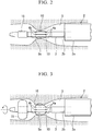
- the balloon 15 has been inflated at a predetermined position on the distal end side of the exposed portions 10 of the wires so that the distal end portion of the flexible sheath 3 is held in a substantially concentric position inside the esophagus by the balloon 15, it is possible to prevent the distal end portion of the flexible sheath which includes the exposed portions 10 of the wires being unintentionally shaken when the incision tool is rotated. As a result, a smooth incision of the narrowing portion Sa of the esophagus can be performed by the exposed portions 10 of the wires.
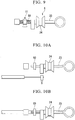
- the rotating ring 51 can be moved in the longitudinal direction of the operating unit main body 23, and after the sliding portion 24 comes up against the rotating ring 51, any further movement thereof towards the distal end side of the flexible sheath is restricted by the moved rotating ring 51.
- the operating unit 6 when the operating unit 6 is being operated, it is possible to more reliably prevent the incision depth to which the narrowing portion Sa of the esophagus is incised by the exposed portions 10 of the wires becoming deeper than is necessary.
Landscapes
- Health & Medical Sciences (AREA)
- Surgery (AREA)
- Life Sciences & Earth Sciences (AREA)
- Medical Informatics (AREA)
- Nuclear Medicine, Radiotherapy & Molecular Imaging (AREA)
- Engineering & Computer Science (AREA)
- Biomedical Technology (AREA)
- Heart & Thoracic Surgery (AREA)
- Vascular Medicine (AREA)
- Molecular Biology (AREA)
- Animal Behavior & Ethology (AREA)
- General Health & Medical Sciences (AREA)
- Public Health (AREA)
- Veterinary Medicine (AREA)
- Surgical Instruments (AREA)
- Endoscopes (AREA)
Claims (4)
- Outil d'incision (1) comprenant :une gaine (3) ;une pluralité de câbles (5) qui sont insérés à travers un espace interne de la gaine (3), par suite de l'insertion d'une partie de ceux-ci à travers à la fois des premiers trous traversants d'insertion de câble (4a) qui sont prévus dans une partie d'extrémité distale de la gaine (3) et des seconds trous traversants d'insertion de câble (4b) qui sont prévus sur le côté extrémité distale de la gaine (3) des premiers trous traversants d'insertion de câble (4a), et sont exposés sur l'extérieur de la gaine (3) entre les premiers trous traversants d'insertion de câble (4a) et les seconds trous traversants d'insertion de câble (4b), les différents câbles (5) étant adaptés pour recevoir un courant à haute fréquence ; etune unité d'actionnement (6) qui est reliée à un côté extrémité de base des câbles (5) et qui est adaptée pour ajuster la longueur des parties exposées (10) des câbles (5) qui sont exposés à l'extérieur de la gaine (3) par déplacement vers l'avant ou vers l'arrière par rapport à la gaine (3) dans la direction longitudinale des câbles (5) ;deux stabilisateurs (16a, 16b) étant disposés à l'intérieur de la gaine (3), chaque stabilisateur (16a, 16b) étant formé par une partie plaque circulaire (17) et par des parties en saillie (18) ayant une section transversale en forme d'éventail et s'étendant à partir d'un côté de la partie plaque circulaire (17) dans une direction perpendiculaire à la partie plaque circulaire (17), et une rainure de guide de câble formée entre les parties en saillie (18), la rainure de guide de câble étant située à une position qui correspond aux premiers trous traversants d'insertion de câble (4a) et aux seconds trous traversants d'insertion de câble (4b),les différents câbles (5) ayant chacun une partie d'insertion côté extrémité de base (11) qui est insérée dans l'espace interne de la gaine (3) sur le côté extrémité de base du premier trou traversant d'insertion de câble (4a), une partie exposée (10) qui s'étend à partir de la partie d'insertion côté extrémité de base (11) vers le côté extrémité distale et qui passe à travers le premier trou traversant d'insertion de câble (4a) de façon à être exposée sur l'extérieur de la gaine (3) en étant guidée par la rainure, une partie d'insertion côté extrémité distale (12) qui s'étend à partir de la partie exposée (10) vers le côté extrémité distale et qui passe à travers le second trou traversant d'insertion de câble (4b) de façon à entrer de nouveau dans l'espace interne de la gaine (3) en étant guidée par la rainure, et une partie courbée (13) qui est située dans une partie d'extrémité sur le côté partie exposée (10) de la partie d'insertion côté extrémité distale (12) et qui courbe le câble (5) dans la direction axiale de la gaine (3) à partir de la direction dans laquelle il entre dans l'espace interne de la gaine (3) par l'intermédiaire du second trou traversant d'insertion de câble (4b), et les différents câbles (5) sont liés ensemble en un unique faisceau dans la partie d'insertion côté extrémité distale (12) sur le côté extrémité distale des parties courbées (13) par un composant de liaison (14).
- Outil d'incision (1) selon la revendication 1, dans lequel une partie ancrage (15, 30, 40), dont le diamètre est plus grand que le diamètre de la gaine (3), est située dans la gaine (3) sur le côté extrémité distale des parties exposées (10) des câbles (5).
- Outil d'incision (1) selon la revendication 1, dans lequel les parties exposées (10) des différents câbles (5) qui sont exposées à l'extérieur de la gaine (3) entre le premier trou traversant d'insertion de câble (4a) et le second trou traversant d'insertion de câble (4b) sont disposées en un motif radial autour de l'axe central de la gaine (3).
- Outil d'incision (1) selon la revendication 1, dans lequel une échelle de gradation (27) qui forme un index d'ajustement de la longueur des parties exposées (10) des câbles (5) est formée sur l'unité d'actionnement (6).
Applications Claiming Priority (1)
| Application Number | Priority Date | Filing Date | Title |
|---|---|---|---|
| JP2007144874A JP2008295729A (ja) | 2007-05-31 | 2007-05-31 | 切開具 |
Publications (3)
| Publication Number | Publication Date |
|---|---|
| EP1997443A2 EP1997443A2 (fr) | 2008-12-03 |
| EP1997443A3 EP1997443A3 (fr) | 2010-03-31 |
| EP1997443B1 true EP1997443B1 (fr) | 2018-10-03 |
Family
ID=39672535
Family Applications (1)
| Application Number | Title | Priority Date | Filing Date |
|---|---|---|---|
| EP08007929.6A Ceased EP1997443B1 (fr) | 2007-05-31 | 2008-04-24 | Outil d'incision |
Country Status (3)
| Country | Link |
|---|---|
| US (1) | US8206402B2 (fr) |
| EP (1) | EP1997443B1 (fr) |
| JP (1) | JP2008295729A (fr) |
Families Citing this family (27)
| Publication number | Priority date | Publication date | Assignee | Title |
|---|---|---|---|---|
| EP2370029B1 (fr) | 2008-12-22 | 2018-05-16 | Medi-Tate Ltd | Implant de coupe radiale |
| US12324603B2 (en) | 2011-09-13 | 2025-06-10 | Venturemed Group, Inc. | Intravascular catheter having an expandable incising portion |
| ES2791766T3 (es) | 2011-09-13 | 2020-11-05 | Pigott John P | Catéter intravascular que tiene una porción de incisión expansible |
| US11559325B2 (en) | 2011-09-13 | 2023-01-24 | Venturemed Group, Inc. | Intravascular catheter having an expandable incising portion and grating tool |
| US10610255B2 (en) | 2011-09-13 | 2020-04-07 | John P. Pigott | Intravascular catheter having an expandable incising portion and medication delivery system |
| US11413062B2 (en) | 2011-09-13 | 2022-08-16 | Venturemed Group, Inc. | Methods for preparing a zone of attention within a vascular system for subsequent angioplasty with an intravascular catheter device having an expandable incising portion and an integrated embolic protection device |
| US10463387B2 (en) | 2011-09-13 | 2019-11-05 | John P. Pigott | Intravascular catheter having an expandable incising portion for incising atherosclerotic material located in a blood vessel |
| US11357533B2 (en) | 2011-09-13 | 2022-06-14 | Venturemed Group, Inc. | Intravascular catheter having an expandable incising portion and abrasive surfaces |
| US20160051278A1 (en) * | 2013-01-23 | 2016-02-25 | Endochoice, Inc. | Surgical Snare Device |
| WO2014116877A2 (fr) * | 2013-01-23 | 2014-07-31 | Endochoice, Inc. | Dispositif d'anse chirurgical |
| US10315014B2 (en) | 2013-07-15 | 2019-06-11 | John P. Pigott | Balloon catheter having a retractable sheath and locking mechanism with balloon recapture element |
| US11202892B2 (en) | 2013-07-15 | 2021-12-21 | John P. Pigott | Balloon catheter having a retractable sheath |
| US10130798B2 (en) | 2013-07-15 | 2018-11-20 | John P. Pigott | Balloon catheter having a retractable sheath and locking mechanism |
| US10828471B2 (en) | 2013-07-15 | 2020-11-10 | John P. Pigott | Balloon catheter having a retractable sheath |
| EP3244815B1 (fr) | 2015-01-13 | 2020-04-22 | Pigott, John, P. | Cathéter intravasculaire ayant une partie extensible |
| US10603069B2 (en) | 2015-01-13 | 2020-03-31 | John P. Pigott | Intravascular catheter balloon device having a tool for atherectomy or an incising portion for atheromatous plaque scoring |
| EP3135206B1 (fr) * | 2015-08-31 | 2020-01-15 | Gefässpraxis Dr. Erpen AG | Dispositif de traitement des varices |
| US10342540B2 (en) | 2015-10-15 | 2019-07-09 | Boston Scientific Scimed, Inc. | Tissue retraction devices and related methods of use |
| US20170150984A1 (en) * | 2015-12-01 | 2017-06-01 | Cook Medical Technologies Llc | Cutting device with precise cutting depth |
| US12569327B2 (en) | 2016-07-01 | 2026-03-10 | Venturemed Group, Inc. | Intravascular catheter having an expandable incising portion and embolic protection device |
| EP3366239B1 (fr) | 2017-02-24 | 2020-08-12 | Pigott, John, P. | Cathéter intravasculaire avec un membre expansible tranchant et des surfaces abrasives |
| WO2019073529A1 (fr) * | 2017-10-10 | 2019-04-18 | オリンパス株式会社 | Système de traitement |
| US11116538B2 (en) * | 2018-11-08 | 2021-09-14 | Gyrus Acmi, Inc. | Medicant delivery device |
| CN112274222B (zh) * | 2020-10-12 | 2021-08-24 | 苏州法兰克曼医疗器械有限公司 | 一种医用带刻度的模块化息肉取出器 |
| US12558116B2 (en) | 2022-03-23 | 2026-02-24 | Venturemed Group, Inc. | Intravascular device for treating fistulas |
| US12408932B2 (en) | 2022-03-23 | 2025-09-09 | Venturemed Group, Inc. | Intravascular device having feedback elements |
| CN116327286B (zh) * | 2023-05-24 | 2023-07-21 | 四川省医学科学院·四川省人民医院 | 一种用于外科手术的可塑形切割缝合器 |
Family Cites Families (21)
| Publication number | Priority date | Publication date | Assignee | Title |
|---|---|---|---|---|
| JPS5727445Y2 (fr) * | 1973-06-20 | 1982-06-15 | ||
| JPS61259662A (ja) * | 1985-05-15 | 1986-11-17 | 旭光学工業株式会社 | 内視鏡用高周波処置具 |
| JPS62194847A (ja) * | 1986-02-21 | 1987-08-27 | 旭光学工業株式会社 | 内視鏡用高周波切開器 |
| US4921484A (en) * | 1988-07-25 | 1990-05-01 | Cordis Corporation | Mesh balloon catheter device |
| JPH0515918A (ja) | 1991-07-10 | 1993-01-26 | Nippon Steel Corp | 熱間タンデム圧延機のスタンド間張力制御装置 |
| JPH0515918U (ja) | 1991-08-16 | 1993-03-02 | オリンパス光学工業株式会社 | 高周波処置具 |
| FI92773C (fi) | 1993-04-27 | 1994-12-27 | Imatran Voima Oy | Päällystetty avojohto suurjännitteelle |
| US5971983A (en) * | 1997-05-09 | 1999-10-26 | The Regents Of The University Of California | Tissue ablation device and method of use |
| JP2000237202A (ja) * | 1999-02-25 | 2000-09-05 | Olympus Optical Co Ltd | 内視鏡用処置具 |
| DE60035263T2 (de) * | 1999-03-02 | 2008-02-21 | Atrionix Inc., Palo Alto | Atriale ablationsvorrichtung mit ballon und sensor |
| JP4294147B2 (ja) * | 1999-03-18 | 2009-07-08 | オリンパス株式会社 | 高周波処置具 |
| US6514248B1 (en) * | 1999-10-15 | 2003-02-04 | Neothermia Corporation | Accurate cutting about and into tissue volumes with electrosurgically deployed electrodes |
| US6689062B1 (en) * | 1999-11-23 | 2004-02-10 | Microaccess Medical Systems, Inc. | Method and apparatus for transesophageal cardiovascular procedures |
| WO2001074260A1 (fr) * | 2000-03-24 | 2001-10-11 | Johns Hopkins University | Cavite peritoneale, procede et dispositif |
| US7517352B2 (en) * | 2000-04-07 | 2009-04-14 | Bacchus Vascular, Inc. | Devices for percutaneous remote endarterectomy |
| JP2004073582A (ja) | 2002-08-20 | 2004-03-11 | Olympus Corp | 生体組織切除具 |
| WO2004041329A2 (fr) * | 2002-11-01 | 2004-05-21 | C.R. Bard, Inc. | Catheter a embout conique, court, a profil bas |
| US7329267B2 (en) | 2002-12-23 | 2008-02-12 | Boston Scientific Scimed, Inc. | Medical cutting devices and methods of use |
| JP4745673B2 (ja) * | 2005-02-02 | 2011-08-10 | Hoya株式会社 | 内視鏡用高周波切開具 |
| JP4731274B2 (ja) * | 2005-10-19 | 2011-07-20 | Hoya株式会社 | 内視鏡用高周波切開具 |
| EP1897506B1 (fr) * | 2006-09-08 | 2010-03-03 | Ethicon Endo-Surgery, Inc. | Instrument chirurgical pour réaliser des myotomies controlées |
-
2007
- 2007-05-31 JP JP2007144874A patent/JP2008295729A/ja active Pending
-
2008
- 2008-04-24 EP EP08007929.6A patent/EP1997443B1/fr not_active Ceased
- 2008-05-08 US US12/117,401 patent/US8206402B2/en not_active Expired - Fee Related
Non-Patent Citations (1)
| Title |
|---|
| None * |
Also Published As
| Publication number | Publication date |
|---|---|
| US8206402B2 (en) | 2012-06-26 |
| US20080300594A1 (en) | 2008-12-04 |
| EP1997443A2 (fr) | 2008-12-03 |
| EP1997443A3 (fr) | 2010-03-31 |
| JP2008295729A (ja) | 2008-12-11 |
Similar Documents
| Publication | Publication Date | Title |
|---|---|---|
| US8206402B2 (en) | Incision tool | |
| US8663238B2 (en) | Treatment tool | |
| EP2065003B1 (fr) | Système de traitement d'endoscope | |
| US7922717B2 (en) | High-frequency treatment tool for endoscope | |
| CN101416863B (zh) | 内窥镜用处理器具及内窥镜用处理器具的制造方法 | |
| KR101030609B1 (ko) | 내시경용 처치구 | |
| EP2574269B1 (fr) | Cathéter équipé d'un ballonnet ayant une section d'introduction à rigidité variable | |
| US20170112569A1 (en) | High-frequency treatment tool and high-frequency treatment system | |
| KR20090029650A (ko) | 내시경용 처치구 | |
| EP3095390B1 (fr) | Écarteur | |
| US12070186B2 (en) | Surgical system and expansion device | |
| JP4819983B2 (ja) | 内視鏡用処置具 | |
| JP6316427B2 (ja) | 安定化機構を備えるガイドカテーテル、及びガイドカテーテルを挿入する方法 | |
| US7896876B2 (en) | High frequency incision instrument for endoscope | |
| CN108289710A (zh) | 内窥镜用高频处置仪 | |
| KR101685009B1 (ko) | 절개장치 및 그를 포함하는 내시경 | |
| EP3075322A1 (fr) | Écarteur | |
| US20170056091A1 (en) | Surgical cutting device | |
| EP2065004A2 (fr) | Système d'incision endoscopique | |
| JP2000262537A (ja) | 内視鏡用処置具 | |
| JP2010082298A (ja) | 内視鏡用バイポーラ型高周波スネア | |
| CN112040895A (zh) | 处置系统 | |
| JP5976752B2 (ja) | 留置カテーテル交換用器具 | |
| JP2005198931A (ja) | 内視鏡用スネア | |
| JP2010063558A (ja) | 内視鏡用処置具 |
Legal Events
| Date | Code | Title | Description |
|---|---|---|---|
| PUAI | Public reference made under article 153(3) epc to a published international application that has entered the european phase |
Free format text: ORIGINAL CODE: 0009012 |
|
| AK | Designated contracting states |
Kind code of ref document: A2 Designated state(s): AT BE BG CH CY CZ DE DK EE ES FI FR GB GR HR HU IE IS IT LI LT LU LV MC MT NL NO PL PT RO SE SI SK TR |
|
| AX | Request for extension of the european patent |
Extension state: AL BA MK RS |
|
| PUAL | Search report despatched |
Free format text: ORIGINAL CODE: 0009013 |
|
| AK | Designated contracting states |
Kind code of ref document: A3 Designated state(s): AT BE BG CH CY CZ DE DK EE ES FI FR GB GR HR HU IE IS IT LI LT LU LV MC MT NL NO PL PT RO SE SI SK TR |
|
| AX | Request for extension of the european patent |
Extension state: AL BA MK RS |
|
| 17P | Request for examination filed |
Effective date: 20100906 |
|
| 17Q | First examination report despatched |
Effective date: 20101007 |
|
| AKX | Designation fees paid |
Designated state(s): DE FR GB IE |
|
| RAP1 | Party data changed (applicant data changed or rights of an application transferred) |
Owner name: OLYMPUS CORPORATION |
|
| RAP1 | Party data changed (applicant data changed or rights of an application transferred) |
Owner name: OLYMPUS CORPORATION |
|
| RAP1 | Party data changed (applicant data changed or rights of an application transferred) |
Owner name: OLYMPUS CORPORATION |
|
| RIN1 | Information on inventor provided before grant (corrected) |
Inventor name: GOTO, HIROAKI |
|
| REG | Reference to a national code |
Ref country code: DE Ref legal event code: R079 Ref document number: 602008057197 Country of ref document: DE Free format text: PREVIOUS MAIN CLASS: A61B0017220000 Ipc: A61B0017320700 |
|
| RIC1 | Information provided on ipc code assigned before grant |
Ipc: A61B 17/22 20060101ALI20180222BHEP Ipc: A61B 17/3207 20060101AFI20180222BHEP Ipc: A61B 17/00 20060101ALI20180222BHEP Ipc: A61B 17/3209 20060101ALI20180222BHEP Ipc: A61B 18/12 20060101ALI20180222BHEP Ipc: A61B 90/00 20160101ALI20180222BHEP |
|
| GRAP | Despatch of communication of intention to grant a patent |
Free format text: ORIGINAL CODE: EPIDOSNIGR1 |
|
| INTG | Intention to grant announced |
Effective date: 20180423 |
|
| GRAS | Grant fee paid |
Free format text: ORIGINAL CODE: EPIDOSNIGR3 |
|
| GRAA | (expected) grant |
Free format text: ORIGINAL CODE: 0009210 |
|
| RIN1 | Information on inventor provided before grant (corrected) |
Inventor name: GOTO, HIROAKI |
|
| AK | Designated contracting states |
Kind code of ref document: B1 Designated state(s): DE FR GB IE |
|
| REG | Reference to a national code |
Ref country code: GB Ref legal event code: FG4D |
|
| REG | Reference to a national code |
Ref country code: IE Ref legal event code: FG4D Ref country code: DE Ref legal event code: R096 Ref document number: 602008057197 Country of ref document: DE |
|
| REG | Reference to a national code |
Ref country code: DE Ref legal event code: R097 Ref document number: 602008057197 Country of ref document: DE |
|
| PGFP | Annual fee paid to national office [announced via postgrant information from national office to epo] |
Ref country code: DE Payment date: 20190425 Year of fee payment: 12 |
|
| PLBE | No opposition filed within time limit |
Free format text: ORIGINAL CODE: 0009261 |
|
| STAA | Information on the status of an ep patent application or granted ep patent |
Free format text: STATUS: NO OPPOSITION FILED WITHIN TIME LIMIT |
|
| 26N | No opposition filed |
Effective date: 20190704 |
|
| GBPC | Gb: european patent ceased through non-payment of renewal fee |
Effective date: 20190424 |
|
| PG25 | Lapsed in a contracting state [announced via postgrant information from national office to epo] |
Ref country code: GB Free format text: LAPSE BECAUSE OF NON-PAYMENT OF DUE FEES Effective date: 20190424 |
|
| PG25 | Lapsed in a contracting state [announced via postgrant information from national office to epo] |
Ref country code: FR Free format text: LAPSE BECAUSE OF NON-PAYMENT OF DUE FEES Effective date: 20190430 |
|
| PG25 | Lapsed in a contracting state [announced via postgrant information from national office to epo] |
Ref country code: IE Free format text: LAPSE BECAUSE OF NON-PAYMENT OF DUE FEES Effective date: 20190424 |
|
| REG | Reference to a national code |
Ref country code: DE Ref legal event code: R119 Ref document number: 602008057197 Country of ref document: DE |
|
| PG25 | Lapsed in a contracting state [announced via postgrant information from national office to epo] |
Ref country code: DE Free format text: LAPSE BECAUSE OF NON-PAYMENT OF DUE FEES Effective date: 20201103 |