EP1997100B1 - Ultraschallsensor - Google Patents
Ultraschallsensor Download PDFInfo
- Publication number
- EP1997100B1 EP1997100B1 EP07712104A EP07712104A EP1997100B1 EP 1997100 B1 EP1997100 B1 EP 1997100B1 EP 07712104 A EP07712104 A EP 07712104A EP 07712104 A EP07712104 A EP 07712104A EP 1997100 B1 EP1997100 B1 EP 1997100B1
- Authority
- EP
- European Patent Office
- Prior art keywords
- housing
- cover
- ultrasound sensor
- damping element
- lid
- Prior art date
- Legal status (The legal status is an assumption and is not a legal conclusion. Google has not performed a legal analysis and makes no representation as to the accuracy of the status listed.)
- Not-in-force
Links
- 238000013016 damping Methods 0.000 claims description 37
- 238000004519 manufacturing process Methods 0.000 claims description 18
- 238000002604 ultrasonography Methods 0.000 claims description 15
- 239000000853 adhesive Substances 0.000 claims description 13
- 230000001070 adhesive effect Effects 0.000 claims description 13
- 238000000034 method Methods 0.000 claims description 8
- 238000010276 construction Methods 0.000 claims description 5
- 238000006073 displacement reaction Methods 0.000 claims description 5
- 238000009413 insulation Methods 0.000 claims description 5
- 239000006260 foam Substances 0.000 claims description 3
- 230000003993 interaction Effects 0.000 claims 1
- 230000008901 benefit Effects 0.000 description 9
- 239000012528 membrane Substances 0.000 description 8
- 239000000463 material Substances 0.000 description 6
- 239000011248 coating agent Substances 0.000 description 5
- 238000000576 coating method Methods 0.000 description 5
- 238000005187 foaming Methods 0.000 description 5
- 239000011324 bead Substances 0.000 description 4
- 230000008569 process Effects 0.000 description 4
- BQCADISMDOOEFD-UHFFFAOYSA-N Silver Chemical compound [Ag] BQCADISMDOOEFD-UHFFFAOYSA-N 0.000 description 3
- 229910052709 silver Inorganic materials 0.000 description 3
- 239000004332 silver Substances 0.000 description 3
- 238000005476 soldering Methods 0.000 description 3
- 229910052782 aluminium Inorganic materials 0.000 description 2
- XAGFODPZIPBFFR-UHFFFAOYSA-N aluminium Chemical compound [Al] XAGFODPZIPBFFR-UHFFFAOYSA-N 0.000 description 2
- 230000005540 biological transmission Effects 0.000 description 2
- 238000005259 measurement Methods 0.000 description 2
- 229910052751 metal Inorganic materials 0.000 description 2
- 239000002184 metal Substances 0.000 description 2
- 239000004033 plastic Substances 0.000 description 2
- 229920001296 polysiloxane Polymers 0.000 description 2
- 238000003466 welding Methods 0.000 description 2
- 229920002323 Silicone foam Polymers 0.000 description 1
- 239000004809 Teflon Substances 0.000 description 1
- 229920006362 Teflon® Polymers 0.000 description 1
- 206010053648 Vascular occlusion Diseases 0.000 description 1
- 238000004026 adhesive bonding Methods 0.000 description 1
- AZDRQVAHHNSJOQ-UHFFFAOYSA-N alumane Chemical group [AlH3] AZDRQVAHHNSJOQ-UHFFFAOYSA-N 0.000 description 1
- 238000005452 bending Methods 0.000 description 1
- 230000003139 buffering effect Effects 0.000 description 1
- 239000003990 capacitor Substances 0.000 description 1
- 230000008859 change Effects 0.000 description 1
- 238000001311 chemical methods and process Methods 0.000 description 1
- 238000006243 chemical reaction Methods 0.000 description 1
- 239000004020 conductor Substances 0.000 description 1
- 238000005260 corrosion Methods 0.000 description 1
- 230000007797 corrosion Effects 0.000 description 1
- 238000005520 cutting process Methods 0.000 description 1
- 238000009826 distribution Methods 0.000 description 1
- 238000005553 drilling Methods 0.000 description 1
- 239000013013 elastic material Substances 0.000 description 1
- 238000005538 encapsulation Methods 0.000 description 1
- 238000001125 extrusion Methods 0.000 description 1
- 230000002349 favourable effect Effects 0.000 description 1
- 239000000945 filler Substances 0.000 description 1
- 238000001746 injection moulding Methods 0.000 description 1
- 238000005304 joining Methods 0.000 description 1
- 238000003754 machining Methods 0.000 description 1
- 230000028161 membrane depolarization Effects 0.000 description 1
- 239000007769 metal material Substances 0.000 description 1
- 238000012544 monitoring process Methods 0.000 description 1
- 230000010355 oscillation Effects 0.000 description 1
- 239000011148 porous material Substances 0.000 description 1
- 239000002243 precursor Substances 0.000 description 1
- 238000009417 prefabrication Methods 0.000 description 1
- 239000003380 propellant Substances 0.000 description 1
- 230000009467 reduction Effects 0.000 description 1
- 239000013514 silicone foam Substances 0.000 description 1
- 239000002689 soil Substances 0.000 description 1
- 230000003595 spectral effect Effects 0.000 description 1
- 239000000126 substance Substances 0.000 description 1
- 239000000725 suspension Substances 0.000 description 1
- 230000007704 transition Effects 0.000 description 1
Images

Classifications
-
- G—PHYSICS
- G10—MUSICAL INSTRUMENTS; ACOUSTICS
- G10K—SOUND-PRODUCING DEVICES; METHODS OR DEVICES FOR PROTECTING AGAINST, OR FOR DAMPING, NOISE OR OTHER ACOUSTIC WAVES IN GENERAL; ACOUSTICS NOT OTHERWISE PROVIDED FOR
- G10K9/00—Devices in which sound is produced by vibrating a diaphragm or analogous element, e.g. fog horns, vehicle hooters or buzzers
- G10K9/12—Devices in which sound is produced by vibrating a diaphragm or analogous element, e.g. fog horns, vehicle hooters or buzzers electrically operated
- G10K9/122—Devices in which sound is produced by vibrating a diaphragm or analogous element, e.g. fog horns, vehicle hooters or buzzers electrically operated using piezoelectric driving means
-
- G—PHYSICS
- G10—MUSICAL INSTRUMENTS; ACOUSTICS
- G10K—SOUND-PRODUCING DEVICES; METHODS OR DEVICES FOR PROTECTING AGAINST, OR FOR DAMPING, NOISE OR OTHER ACOUSTIC WAVES IN GENERAL; ACOUSTICS NOT OTHERWISE PROVIDED FOR
- G10K11/00—Methods or devices for transmitting, conducting or directing sound in general; Methods or devices for protecting against, or for damping, noise or other acoustic waves in general
- G10K11/002—Devices for damping, suppressing, obstructing or conducting sound in acoustic devices
-
- Y—GENERAL TAGGING OF NEW TECHNOLOGICAL DEVELOPMENTS; GENERAL TAGGING OF CROSS-SECTIONAL TECHNOLOGIES SPANNING OVER SEVERAL SECTIONS OF THE IPC; TECHNICAL SUBJECTS COVERED BY FORMER USPC CROSS-REFERENCE ART COLLECTIONS [XRACs] AND DIGESTS
- Y10—TECHNICAL SUBJECTS COVERED BY FORMER USPC
- Y10T—TECHNICAL SUBJECTS COVERED BY FORMER US CLASSIFICATION
- Y10T29/00—Metal working
- Y10T29/49—Method of mechanical manufacture
- Y10T29/49002—Electrical device making
- Y10T29/49007—Indicating transducer
Definitions
- the present invention relates to an ultrasonic sensor for a vehicle and a corresponding method for producing the same.
- Ultrasonic sensors are used in motor vehicles, for example, as a parking aid, for which purpose in particular a so-called Nahmessele in a Entfemungs Society of less than 30 cm is a crucial functional requirement. They consist generally of a housing and a transducer element arranged therein (sieche zb JP 10 206 528 A ).
- the housing is usually formed or milled from a metallic material, such as aluminum. It is coated for corrosion protection and Lackierfugn with a primer.
- An electromechanical transducer element eg, a piezoelectric element
- the housing is filled with a damping material.
- a damping material is an injected silicone foam.
- a contacting of the transducer elements consists for example in that a connecting line is attached to the metallized transducer element top of the piezoelectric element, wherein the underside of the transducer element is fixed with an adhesive on the bottom of the housing.
- the metallic housing or the metallic membrane forms the second terminal or the second electrode (cathode).
- the second connecting line is then soldered to the conductive housing (made of aluminum, for example), suitably connected by drilling the housing wall thereto or fastened to a housing journal, which is considered to be disadvantageous in terms of the number of components and the production outlay.
- the contacting of the transducer element underside is carried out by a so-called Umking mich.
- the piezoceramic disc is completely coated with silver and at the top a D-shaped separating cut (see Fig. 2 ) of the silver coating. This creates on the top two contactable by strand, bonds or other conductors surfaces.
- the disadvantage here is the non-homogeneous field / force distribution in the piezoceramic, since the upper surface is only partially covered by the D-section through the one (anode) contact (inhomogeneous plate capacitor).
- a further disadvantage is that, in the case of an incorrect bonding (depending on the thickness of the bonding and roughness of the bottom) of the underside of the transducer element to the bottom of the housing, the housing is not contacted by the Umutton michitzer to ground (GND or ground) and the sensor undesirable to work as a capacitive sensor, where he is sensitive to electrical interference.
- UTD Umbit or ground
- thermocompression welding with low mass contribution is functionally advantageous in the series.
- the JP 2002238095 A describes an ultrasonic sensor with a lid, wherein the housing is formed on the one hand smooth-walled and on the other hand with gradations that require increased manufacturing costs.
- the cover may be staggered in the housing to dampen certain vibration modes, the adjustment of this position means increased expense.
- the lid has a smooth surface, whereby it is made thicker than the pot membrane, but otherwise not specified. Has cut-outs or bulges.
- the concept is to store the unilaterally free oscillator "pot wall" at the top hard and thus produce a bilaterally suspended bending shaft (Drawing 6 and 7).
- the lid is glued.
- the terminals are attached to the transducer element and to the housing in unspecified manner.
- the DE 296 14 691 U 1 describes an ultrasonic sensor in which a felt insert is held by a cover disk above a transducer element. The contacting of the transducer element takes place via a direct connection and via a contact pin inserted in a weighting ring.
- the structure is complex and includes the construction of a prestressed Teflon film.
- the DE 101 25 272 A1 describes an ultrasonic sensor and its manufacturing method. Its transducer element is covered by three different layers, wherein a cover covers three housing parts. A conductive housing part, which forms the membrane, is provided with a caulked connection. This writing refers only to the Generation of decoupling ring between oscillating membrane and housing by encapsulation with silicone.
- An ultrasonic transducer used in the DE 197 44 229 A1 has a housing with a bead and a housing closing decoupling ring on.
- the decoupling ring forms in one embodiment simultaneously use as a damping material within the housing. In another embodiment, it has a cylindrical passage opening which is filled with a damping material. A closer specification of the passage opening in terms of their geometry and function is not given.
- the decoupling ring also serves as a holder for the terminals of the transducer element, wherein connection of the housing is present.
- the DE 44 34 692 A1 is an example illustrating the attachment of a piezoceramic with conductive adhesive on a metal plate of an ultrasonic sensor.
- the ultrasonic sensor according to the invention has the advantage that it meets the requirements of the decisive Nahmess sparkle with a small number of components. Another advantage is that the components are designed so that a production of the ultrasonic sensor has no difficult-to-control processes and manual production is made possible in a simple manner.
- the ultrasonic sensor has a housing which is closed by a lid, which at the same time includes a damping element, allows the implementation of the connecting line and the contacting of the housing in a simple manner. During manufacture, another damping element is inserted into the housing.
- the cover has a geometry shape which is designed in such a way that disturbing wall waves are introduced, if possible, without reflection into the plastic damping element introduced into it.
- the housing is closed with a lid whose contour is adapted to the course of the housing inner wall in order to achieve a smooth transition of the wall vibration in the lid.
- the lid is connected to the housing by means of an adhesive.
- an adhesive for ease of manufacture, it is advantageously provided that the connection of the cover to the housing by means of a protruding from the edge of the mold section connecting element in cooperation with a corresponding receptacle in the housing is formed non-positively. This can be, for example, a so-called clip connection. Between the lid and the pot wall, a circumferential traction is provided.
- the housing oscillations are not prevented by a hard suspension at the top of the housing wall, but as possible adapted to the mechanical impedance converted into thermal energy in the second damping element.
- the lid is provided with a through opening in which the damping element is arranged, wherein the opening has a continuous edge profile of its inner wall.
- the continuous edge course ensures that the wall vibrations transmitted into the cover are adapted to migrate into this damping element where they are converted into thermal energy, whereby they swing out in a damped way.
- the cover is provided with feedthroughs for connection lines of the transducer element.
- the lid has at least one contacting device for a electrically conductive connection between a connection element and the housing. This advantageously achieves that on the one hand a transducer element can be used, which is only metallized on one side, wherein the lower electrode is formed by the conductive housing. On the other hand, there is the advantage that when applying the lid to the housing at the same time a contacting of the housing takes place, thereby eliminating additional processing of the housing and the production is simplified.
- the contacting device is designed as an insulation displacement construction or as a spring contact.
- the insulation displacement structure is integrated in the lid.
- the contacting can be a conductive adhesive, with the advantage that the conductive adhesive simultaneously forms the non-positive connection of the lid with the housing.
- a further embodiment provides that the outer diameter of the cover for holding a decoupling ring is slightly larger than the outer diameter of the housing. This increases the possibility of using the sensor for other applications. The need for a retaining bead or groove on the metallic housing wall is thus eliminated. There is another advantage in that the mechanical impedance of the wall is not changed.
- the housing advantageously has no bead or groove. As a result, a change in the mechanical impedance of the housing wall and thus a reflection point for vibrations in the housing wall are avoided.
- the first damping element is designed as an insertable into the housing open-pore foam insert component. This can be done manually in a simple manner before closing the housing.
- connection cables are soldered to the corresponding connection points and then the first damping element is inserted into the housing.
- the ultrasonic sensor remains at its operating frequency 48 kHz low impedance and thus efficient. This is done by selective attenuation of the membrane with the insert 1. It can be controlled with smaller transmission voltages and has higher generator voltages in the microphone range.
- the former is synonymous with a reduced risk of depolarization of the piezoceramic, less overdriving a transformer in the non-linearity or the possibility of a smaller transformer gear ratio and thereby the use of a smaller sized driver stage.
- the lid itself can be preproduced as a precursor with its introduced damping material regardless of cycle times of the sensor manufacturing, buffering a single-stranded production line can be avoided.
- This damping material can be designed specifically for the wall vibrations.
- the waiver of the bead in the case means advantages in the rough production of the housing by extrusion.
- the senor Due to the high transmission efficiency and improved noise / noise margins when receiving, the sensor is well suited for realizing larger ranges for advanced functions such as parking space measurement, blind spot monitoring, LSF, etc.
- the Nahmes emphasis the sensor of the invention improves by the lid insert in a non-foamed housing of about 28 ... 30 cm to about 22 ... 23 cm on the plausibilized binary signal.
- FIG. 1 an inventive sensor 1 is shown in a sectional view as an embodiment.
- a housing 2 has a bottom 5 as a membrane. Furthermore, the housing 2 has on its upper side an edge 4 with an opening with a contour 6 (see Fig. 2 ), in which a lid 17 is inserted.
- the housing 2 is preferably a die-pressed aluminum part.
- transducer element 8 is fastened by means of a connecting element 7, here an adhesive, on the bottom of the housing 2.
- the transducer element 8 has only a one-sided first coating 9 made of a suitable metal, for example silver.
- the coating 9 is connected via a soldering in a first connection point 12 to a first supply line 14.
- transducer elements 8, in which a second coating 10 is present on its underside, can be used, wherein the connecting element 7 is then formed as a conductive adhesive.
- a first damping element 16 is inserted for damping the vibration of the membrane.
- the first lead 14 is laid either around the first damping element 16 around or in a bulge or an incision of the damping element 16.
- the contacting of the housing 2 for connection of the underside of the transducer element 8 is formed by a contacting device 30, which is located on the underside of the lid 17 on a mold section 23.
- This contacting device 30 can be embodied, for example, as an insulation displacement construction, spring construction, or simply a conductive adhesive.
- the conductive adhesive can also form a frictional connection of the lid 17 with the housing 2 at the same time.
- the contacting device 30 is connected within the lid 17 with a connection element 29, which in this example protrudes beyond the lid 17, to which a second supply line can be connected, for example by soldering.
- the cover 17 closes the housing 2 by its form portion 23 is positively inserted into the contour 6 of the housing opening.
- a frictional connection can be made by means of an adhesive and / or a connecting device.
- a connection device may be, for example, a protruding from the edge of the mold portion 23 element which is locked with the housing 2 suitable, for example a clip connection.
- the housing 2 may have suitable grooves (not shown).
- an opening 20 is introduced, which is filled with a second damping element 28, for example a plasto-elastic material. This opening 20 will be described in more detail below.
- the sensor 1 cover 17 and housing 2 are prefabricated, either together on a line or separately.
- the prefabrication can be done independently.
- the sensor 1 is manufactured, the first lead is soldered to the glued into the housing 2 transducer element 8. Then the first damping element 16 is inserted.
- the first supply line 14 may already be carried out in the lid 17 or glued. Then, the housing is closed with the lid 17, the above-mentioned connection possibilities are used.
- the connection of the connecting element 29 may have been made before or is now made.
- the sensor 1 may also be equipped with a re-contacted transducer element 8, which in Fig. 2 in a plan view of an open housing 2 is shown only schematically.
- the transducer element 8 is of a metallic coating 8, which is provided on the top with a parting line 11 in D-shape. As a result, two connection regions are formed, which are each contacted with a supply line 14, 15 in connection points 12, 13.
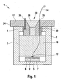
- Fig. 3 shows the view of its bottom 19 with the mold portion 23 which extends in a direction on both sides from the center of the lid 17 as a rectangle with rounded corners. Its shape is the contour 6 of the housing 2 (see Fig. 2 ) and may also have other configurations.
- the passages 25, 26 for the leads 14, 15 of the transducer element 8 are provided in the region of the mold section 23, since this ensures a wider guide.
- the supply lines can also be injected into the lid 17, which consists for example of a suitable plastic.
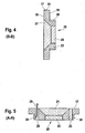
- the opening 20 penetrates the lid as Fig. 4 in a sectional view along the line BB and Fig. 5 along the line AA Fig. 3 shows.
- the opening 20 has first and second opening portions 21 and 22, wherein the first opening portion is tapered.
- the inner walls 27 of the opening portions 21, 22 have a continuous edge profile and thus a continuous taper of the lid thickness for the advantageous introduction of vibration in the second damping element 28, which is introduced into the opening 20.
- the contacting device 30 is arranged on the outside of the mold section 23, the contacting device 30 is arranged. It may also be attached to the underside 19 of the lid 17.
- the top 18 of the lid 17 is configured just in this embodiment. But it can also have other suitable forms.
- the invention is not limited to the embodiments described above, but modifiable in a variety of ways.
- the contacting device 30 may be a combination of insulation displacement connection, spring contact and conductive adhesive.
- the second damping element 28 can also be created together with the cover 20 in a two-component injection molding process.
- lid 17 and the housing 2 are connected by a screwing operation with, for example, a quarter turn, wherein the mold portion 23 may have a suitable shape with a cutting lug.
Landscapes
- Physics & Mathematics (AREA)
- Engineering & Computer Science (AREA)
- Acoustics & Sound (AREA)
- Multimedia (AREA)
- Measurement Of Mechanical Vibrations Or Ultrasonic Waves (AREA)
- Transducers For Ultrasonic Waves (AREA)
- Measurement Of Velocity Or Position Using Acoustic Or Ultrasonic Waves (AREA)
Description
- Die vorliegende Erfindung betrifft einen Ultraschallsensor für ein Fahrzeug und ein entsprechendes Verfahren zum Herstellen eines solchen.
- Ultraschallsensoren werden bei Kraftfahrzeugen zum Beispiel als Einparkhilfe eingesetzt, wobei zu diesem Zweck insbesondere eine so genannte Nahmessfähigkeit in einem Entfemungsbereich von unter 30 cm eine entscheidende funktionale Anforderung ist. Sie bestehen im Allgemeinen aus einem Gehäuse und einem darin angeordneten Wandlerelement (sieche z.b.
JP 10 206 528 A - Diese Herstellungsschritte sind aus verschiedenen Gründen technisch nicht trivial. Insbesondere bedürfen die chemischen Prozesse des Klebens und Schäumens exakter Parameter und sind in der Fertigung schwierig umzusetzen. Ein Gleiches gilt für die Kontaktierung der Wandlerelemente mit Bonds, was zum Beispiel mittels Thermokompressions-Schweißen (TKS) erfolgt.
- Anstelle einer Ausschäumung des Gehäuseinnenraums kann man eine Bedämpfung durch Einlage von Schaumteilen in das Gehäuse erreichen. Dadurch wäre der Produktionsschritt des Ausschäumens durch einen manuell einfach zu beherrschenden Schritt ersetzt. Allerdings zeigt sich dabei, dass solche Sensoren dadurch ein ungünstigeres Ausschwingverhalten im Vergleich zu Ausführungen mit einer Ausschäumung aufweisen, welches die entscheidende funktionale Anforderung nach einer Nahmessfähigkeit beeinträchtigt.
- Durch Messungen der spektralen Anteile der Ausschwingvorgänge hat sich herausgestellt, dass ein wesentlicher Anteil auf Resonanzen außerhalb der Arbeitsfrequenz (48 kHz) des Ultraschallsensors beruht, wobei insbesondere Anteile um 30 kHz und 70 kHz bedeutend sind. Diese werden durch Kipp- und Knautschbewegungsabläufe in der Gehäusewand verursacht. Zur Bedämpfung der Gehäusewandschwingungen werden weiterhin. Gehäusefüllstoffe verwendet, die aus Dämpfungswerkstoffen bestehen und/oder solche zusätzlich enthalten.
- Eine Kontaktierung der Wandlerelemente besteht zum Beispiel darin, dass eine Anschlussleitung an der metallisierten Wandlerelementoberseite des Piezoelementes angebracht wird, wobei die Unterseite des Wandlerelementes mit einem Kleber auf dem Boden des Gehäuses befestigt ist. Das metallische Gehäuse, bzw. die metallische Membran bildet den zweiten Anschluss bzw. die zweite Elektrode (Kathode). An das leitfähige Gehäuse (beispielsweise aus Aluminium) wird dann die zweite Anschlussleitung angelötet, durch Anbohren der Gehäusewand mit dieser geeignet leitend verbunden oder an einem Gehäusezapfen befestigt, was hinsichtlich der Anzahl von Bauteilen und des Fertigungsaufwands als nachteilig empfunden wird.
- Bei einem anderen Beispiel erfolgt die Kontaktierung der Wandlerelementunterseite durch eine so genannte Umkontaktierung. Dazu wird die Piezokeramikscheibe vollständig mit Silber beschichtet und an der Oberseite ein D-formiger Trennungsschnitt (siehe
Fig. 2 ) der Silberbeschichtung durchgeführt. Dadurch entstehen auf der Oberseite zwei durch Litze, Bonds oder sonstige Leiter kontaktierbare Flächen. - Nachteilig hierbei ist die nichthomogene Feld-/Kraftverteilung in der Piezokeramik, da die obere Fläche durch den D-Schnitt nur noch partiell durch den einen (Anoden-) Kontakt bedeckt ist (inhomogener Plattenkondensator). Ein weiterer Nachteil besteht darin, dass bei einer nicht korrekten Klebung (abhängig von Dicke der Klebung und Rauhigkeit des Bodens) der Unterseite des Wandlerelementes zum Boden des Gehäuses das Gehäuse durch die Umkontaktierung nicht an Masse (GND bzw. Ground) kontaktiert ist und der Sensor unerwünscht als kapazitiver Sensor arbeiten kann, wobei er empfindlich auf elektrische Störfelder ist. Außerdem wird es als nachteilig empfunden, dass auf der Oberseite des Wandlerelementes durch die Umkontaktierung zwei Kontakte im Bereich der Nutzschwingung erzeugt sind. Nebst Beeinflussung durch den Kontakt im Sinne eines gekoppelten Schwingers entsteht in der Praxis eine Verringerung der Resonanzfrequenz proportional zum Massebeitrag der Kontaktierung (zum Beispiel Lötpunkte). Aus diesem Grund ist in der Serie Thermokompressionsschweißen mit geringem Massebeitrag funktional vorteilhaft.
- Die
JP 2002238095 A - Die
DE 296 14 691 U 1 beschreibt einen Ultraschallsensor, bei welchem oberhalb eines Wandlerelementes eine Filzeinlage von einer Deckscheibe gehalten ist. Die Kontaktierung des Wandlerelementes erfolgt über einen Direktanschluss und über einen in einem Beschwerungsring eingesetzten Kontaktstift. Der Aufbau ist aufwändig und schließt die Konstruktion einer vorgespannten Teflonfolie ein. - In der
DE 197 54 891 C1 ist ein Ultraschallwandler beschrieben, welcher über einem Wandlerelement zwei Dämpfungsstoffe aufweist. Die Wandstärke des Gehäuses ist gegenüber der Membran groß, wobei diese Gehäusewand einen Kontaktstift enthält. - Die
DE 101 25 272 A1 beschreibt einen Ultraschallsensor und sein Herstellverfahren. Sein Wandlerelement ist von drei unterschiedlichen Lagen bedeckt, wobei ein Deckel drei Gehäuseteile überdeckt. Ein leitender Gehäuseteil, der die Membran bildet, ist mit einem verstemmten Anschluss versehen. Diese Schrift bezieht sich allein auf die Erzeugung des Entkopplungsrings zwischen schwingender Membran und Gehäuse durch Umspritzung mit Silikon. - Ein Ultraschallwandler, der in der
DE 197 44 229 A1 beschrieben ist, weist ein Gehäuse mit einem Wulst und einem das Gehäuse verschließenden Entkopplungsring auf. Der Entkopplungsring bildet in einer Ausführung gleichzeitig einen Einsatz als Dämpfungsmaterial innerhalb des Gehäuses. In einer anderen Ausführung weist er eine zylindrische Durchgangsöffnung auf, die mit einem Dämpfungsstoff angefüllt ist. Eine nähere Spezifizierung der Durchgangsöffnung hinsichtlich ihrer Geometrie und Funktion wird nicht gegeben. Der Entkopplungsring dient gleichzeitig als Halterung für die Anschlüsse des Wandlerelementes, wobei Anschluss des Gehäuses vorhanden ist. - Die
DE 44 34 692 A1 ist ein Beispiel zur Illustration der Befestigung einer Piezokeramik mit Leitkleber auf einer Metallplatte eines Ultraschallsensors. - Der erfindungsgemäße Ultraschallsensor weist demgegenüber den Vorteil auf, dass er mit einer geringen Anzahl an Bauteilen die Anforderungen an die entscheidende Nahmessfähigkeit erfüllt. Ein weiterer Vorteil besteht darin, dass die Bauteile so gestaltet sind, dass eine Herstellung des Ultraschallsensors keine schwer zu beherrschenden Prozesse aufweist und eine manuelle Fertigung in einfacher Weise ermöglicht wird.
- Der Kern der Erfindung besteht darin, dass der Ultraschallsensor ein Gehäuse aufweist, das mit einem Deckel verschlossen ist, der gleichzeitig ein Dämpfungselement beinhaltet, die Durchführung der Anschlussleitung und die Kontaktierung des Gehäuses in einfacher Weise ermöglicht. Bei der Herstellung wird in das Gehäuse ein weiteres Dämpfungselement eingelegt.
- Ein besonderer Vorteil besteht darin, dass der Deckel eine Geometrieform aufweist, welche dergestalt ausgeführt ist, dass störenden Wandwellen möglichst ohne Reflexion in das in ihm eingebrachte plastische Dämpfungselement eingeleitet werden.
- Gemäß der Erfindung weist der Ultraschallsensor, insbesondere für ein Fahrzeug, mit einem Gehäuse Folgendes auf:
- ein im Gehäuse auf dessen Boden angebrachtes Wandlerelement zur Erzeugung von Ultraschallschwingungen;
- ein im Gehäuse angeordnetes erstes Dämpfungselement zur Schwingungsdämpfung des Bodens; und
- einen Deckel zum Verschluss des Gehäuses,
- wobei der Deckel mit einem zweiten Dämpfungselement versehen ist und im Bereich des zweiten Dämpfungselementes eine stetige Verjüngung der Deckeldicke aufweist.
- Das Gehäuse ist mit einem Deckel verschlossen, dessen Kontur dem Verlauf der Gehäuseinnenwand angepasst ist, um einen schlüssigen Übergang der Wandschwingung in den Deckel zu erreichen.
- Der Deckel ist mit dem Gehäuse mittels eines Klebers verbunden. Für eine einfache Herstellung ist vorteilhaft vorgesehen, dass die Verbindung des Deckels mit dem Gehäuse mittels eines von dem Rand des Formabschnitts hervorstehenden Verbindungselementes in Zusammenwirkung mit einer korrespondierenden Aufnahme im Gehäuse kraftschlüssig ausgebildet ist. Dies kann beispielsweise eine so genannt Klipsverbindung sein. Zwischen Deckel und Topfwand ist ein umlaufender Kraftschluss vorgesehen.
- Hierdurch werden die Gehäuseschwingungen an der Oberseite der Gehäusewand nicht durch eine harte Aufhängung unterbunden, sondern möglichst an die mechanische Impedanz angepasst in thermische Energie im zweiten Dämpfungselement umgewandelt.
- Der Deckel ist mit einer durchgehenden Öffnung versehen, in welcher das Dämpfungselement angeordnet ist, wobei die Öffnung einen stetigen Kantenverlauf ihrer Innenwand aufweist. Durch den stetigen Kantenverlaufwird erreicht, dass die in den Deckel übertragenen Wandschwingungen angepasst in dieses Dämpfungselement wandern und dort in thermische Energie umgewandelt werden, wobei sie bedämpft ausschwingen.
- Der Deckel ist mit Durchführungen für Anschlussleitungen des Wandlerelementes versehen. Weiterhin weist der Deckel mindestens eine Kontaktiereinrichtung für eine elektrisch leitende Verbindung zwischen einem Anschlusselement und dem Gehäuse auf. Damit wird vorteilhaft erreicht, dass einerseits ein Wandlerelement verwendet werden kann, das nur einseitig metallisiert ist, wobei die untere Elektrode durch das leitfähige Gehäuse gebildet wird. Andererseits besteht der Vorteil, dass beim Aufbringen des Deckels auf das Gehäuse gleichzeitig eine Kontaktierung des Gehäuses erfolgt, wodurch zusätzliche Bearbeitungen des Gehäuses entfallen und die Herstellung vereinfacht wird.
- Dazu ist es bevorzugt, dass die Kontaktiereinrichtung als eine Schneidklemmkonstruktion oder als ein Federkontakt ausgebildet ist. In bevorzugter Weise ist die Schneidklemmkonstruktion im Deckel integriert.
- Alternativ kann die Kontaktiereinrichtung ein Leitkleber sein, wobei der Vorteil besteht, dass der Leitkleber gleichzeitig die kraftschlüssige Verbindung des Deckels mit dem Gehäuse bildet.
- Eine weitere Ausführungsform sieht vor, dass der Außendurchmesser des Deckels zur Halterung eines Entkopplungsrings etwas größer als der Außendurchmesser des Gehäuses ausgebildet ist. Dadurch wird die Einsatzmöglichkeit des Sensors für weitere Anwendungen vergrößert. Die Notwendigkeit einer Haltewulst bzw. Nut an der metallischen Gehäusewand entfällt somit. Darin besteht ein weiterer Vorteil, dass die mechanische Impedanz der Wand nicht verändert ist.
- Somit besitzt das Gehäuse besitzt vorteilhafterweise keinen Wulst oder Nut. Dadurch werden eine Änderung der mechanischen Impedanz der Gehäusewand und damit eine Reflexionsstelle für Schwingungen in der Gehäusewand vermieden.
- Zur Vermeidung einer Oberschwingung von ca. 54 kHz ist vorgesehen, dass das erste Dämpfungselement als ein in das Gehäuse einlegbares offenporiges Schaumeinlagebauteil ausgebildet ist. Dies kann vor Verschluss des Gehäuses manuell in einfacher Weise erfolgen.
- Ein erfindungsgemäßes Verfahren zum Herstellen eines oben beschriebenen Ultraschallsensors nach weist folgende Verfahrensschritte auf:
- (V1) Anfertigen des Deckels und Einbringen des zweiten Dämpfungselementes in die Öffnung des Deckels;
- (V2) Bearbeiten des teilbestückten Gehäuses; und
- (V3) Herstellen des Ultraschallsensors durch Verschließen des Gehäuses mit dem Deckel.
- Dabei ist bevorzugt, dass beim Bearbeiten des teilbestückten Gehäuses die Anschlussleitungen an die entsprechenden Anschlusspunkte angelötet werden und danach das erste Dämpfungselement in das Gehäuse eingelegt wird.
- Der Ultraschallsensor bleibt auf seiner Arbeitsfrequenz 48 kHz niederohmig und damit effizient. Dies erfolgt durch die gezielte Bedämpfung der Membran mit dem Einlegeteil 1. Er ist mit kleineren Sendespannungen ansteuerbar und hat im Mikrofonbereich höhere Generatorspannungen. Ersteres ist gleichbedeutend mit einem verringerten Risiko von Depolarisation der Piezokeramik, geringeres Übersteuern eines Übertragers in die Nichtlinearität bzw. die Möglichkeit eines kleineren Übertrager-Übersetzungsverhältnisses und dadurch der Einsatz einer kleiner dimensionierten Treiberstufe.
- Das schwer zu beherrschende Reaktionsgleichgewicht zwischen Treibmittelausdehnung und Adhäsion eines Silikons beim Schäumprozess desselben wird durch einen einfachen mechanischen Fügeprozess des Deckels ersetzt.
- Der Deckel selbst kann als Vorprodukt mit seinem eingebrachten Dämpfungswerkstoff unabhängig von Taktzeiten der Sensorfertigung vorproduziert werden, Pufferungen einer einsträngigen Produktionslinie können vermieden werden. Dieser Dämpfungswerkstoff kann gezielt für die Wandschwingungen ausgelegt werden.
- Der Verzicht auf den Wulst beim Gehäuse bedeutet Vorteile bei der Rohfertigung des Gehäuses durch Fließpressen.
- Durch die hohe Sendewirkung und verbesserten Rausch-/Störabstände beim Empfang ist der Sensor gut geeignet zur Realisierung größerer Reichweiten für erweiterte Funktionen wie Parklückenvermessung, Überwachung toter Winkel, LSF usw.
- Die Nahmessfähigkeit des erfindungsgemäßen Sensors verbessert sich durch den Deckeleinsatz bei einem ungeschäumten Gehäuse von ca. 28...30 cm auf ca. 22...23 cm auf dem plausibilisierten binären Signal.
- Weitere Vorteile und Merkmale der Erfindung sind der Beschreibung und den Zeichnungen entnehmbar.
- Die Erfindung wird nachfolgend anhand des in den Figuren der Zeichnung angegebenen Ausführungsbeispiels näher erläutert.
- Es zeigt dabei.
-
FIG. 1 eine schematische Schnittdarstellung eines beispielhaften Ultraschallsensors gemäß der Erfindung; -
FIG. 2 eine Draufsicht auf das Gehäuse ohne Deckel eines Sensors mit einem umkontaktierten Wandlerelement; -
FIG. 3 eine Draufsicht auf die Unterseite des Deckels des Sensors nachFig. 1 ; -
FIG. 4 eine Schnittdarstellung des Deckels nachFig. 3 längs Linie B-B; und -
FIG. 5 eine Schnittdarstellung des Deckels nachFig. 3 längs Linie A-A. - Gleiche oder ähnliche Bauteile mit gleichen oder ähnlichen Funktionen sind in den Figuren mit gleichen Bezugszeichen versehen.
- In
Fig. 1 ist ein erfindungsgemäßer Sensor 1 in einer Schnittdarstellung als ein Ausführungsbeispiel gezeigt. Ein Gehäuse 2 weist einen Boden 5 als Membran auf. Weiterhin besitzt das Gehäuse 2 an seiner Oberseite einen Rand 4 mit einer Öffnung mit einer Kontur 6 (sieheFig. 2 ), in die ein Deckel 17 eingesetzt ist. Das Gehäuse 2 ist vorzugsweise ein fließgepresstes Aluminiumteil. - Im Inneren des Gehäuses 2 ist ein Wandlerelement 8 mittels eines Verbindungselementes 7, hier ein Kleber, auf dem Boden des Gehäuses 2 befestigt. Das Wandlerelement 8 besitzt nur eine einseitige erste Beschichtung 9 aus einem geeigneten Metall, beispielsweise Silber. Die Beschichtung 9 ist über eine Lötung in einem ersten Anschlusspunkt 12 mit einer ersten Zuleitung 14 verbunden. Auch Wandlerelemente 8, bei denen eine zweite Beschichtung 10 an ihrer Unterseite vorhanden ist, können verwendet werden, wobei das Verbindungselement 7 dann als ein Leitkleber ausgebildet ist.
- Über dem Wandlerelement 8 ist ein erstes Dämpfungselement 16 eingelegt zur Bedämpfung der Schwingung der Membran. Die erste Zuleitung 14 ist entweder um das erste Dämpfungselement 16 herum oder in einer Ausbuchtung oder einem Einschnitt des Dämpfungselementes 16 verlegt.
- Die Kontaktierung des Gehäuses 2 zum Anschluss der Unterseite des Wandlerelementes 8 wird durch eine Kontaktiereinrichtung 30 gebildet, welche sich an der Unterseite des Deckels 17 an einem Formabschnitt 23 befindet. Diese Kontaktiereinrichtung 30 kann zum Beispiel als eine Schneidklemmkonstruktion, Federkonstruktion, oder in einfacher Weise ein Leitkleber, ausgeführt sein. Der Leitkleber kann auch gleichzeitig eine kraftschlüssige Verbindung des Deckels 17 mit dem Gehäuse 2 bilden. Die Kontaktiereinrichtung 30 ist innerhalb des Deckels 17 mit einem Anschlusselement 29 verbunden, das in diesem Beispiel über dem Deckel 17 hervorsteht, an welches eine zweite Zuleitung zum Beispiel durch Lötung anschließbar ist.
- Der Deckel 17 verschließt das Gehäuse 2, indem sein Formabschnitt 23 formschlüssig in die Kontur 6 der Gehäuseöffnung eingesetzt ist. Eine kraftschlüssige Verbindung kann mittels eines Klebers und/oder einer Verbindungseinrichtung erfolgen. Eine solche Verbindungseinrichtung kann beispielsweise ein vom Rand des Formabschnitts 23 hervorstehendes Element sein, das mit dem Gehäuse 2 geeignet verrastet, zum Beispiel eine Klipsverbindung. Dabei kann das Gehäuse 2 geeignete Nuten (nicht gezeigt) aufweisen.
- In dem Deckel 17 ist eine Öffnung 20 eingebracht, welche mit einem zweiten Dämpfungselement 28 gefüllt ist, zum Beispiel ein plasto-elastisches Material. Diese Öffnung 20 wird weiter unten noch ausführlicher beschrieben.
- Zum Herstellen des Sensors 1 werden Deckel 17 und Gehäuse 2 vorgefertigt, entweder zusammen auf einer Linie oder auch separat. Die Vorfertigung kann unabhängig voneinander erfolgen.
- Der Sensor 1 wird hergestellt, die erste Zuleitung an das in das Gehäuse 2 eingeklebte Wandlerelement 8 angelötet wird. Daraufhin wird das erste Dämpfungselement 16 eingelegt. Die erste Zuleitung 14 kann sich schon im Deckel 17 durchgeführt oder auch eingeklebt befinden. Dann wird das Gehäuse mit dem Deckel 17 verschlossen, wobei die oben angeführten Verbindungsmöglichkeiten benutzt werden. Der Anschluss des Anschlusselementes 29 kann vorher erfolgt sein oder wird jetzt vorgenommen.
- Der Sensor 1 kann auch mit einem umkontaktierten Wandlerelement 8 ausgerüstet sein, was in
Fig. 2 in einer Draufsicht auf ein geöffnetes Gehäuse 2 nur schematisch gezeigt ist. Das Wandlerelement 8 ist von einer metallischen Beschichtung 8, die auf der Oberseite mit einer Trennfuge 11 in D-Form versehen ist. Dadurch sind zwei Anschlussbereiche gebildet, die jeweils mit einer Zuleitung 14, 15 in Anschlusspunkten 12, 13 kontaktiert sind. - Im Folgenden wird der Deckel 17 ausführlicher beschrieben.
Fig. 3 zeigt die Ansicht seiner Unterseite 19 mit dem Formabschnitt 23, der sich in einer Richtung beidseitig von der Mitte des Deckels 17 als ein Rechteck mit abgerundeten Ecken erstreckt. Seine Form ist der Kontur 6 des Gehäuses 2 (sieheFig. 2 ) angepasst und kann auch andere Ausgestaltungen aufweisen. Die Durchführungen 25, 26 für die Zuleitungen 14, 15 des Wandlerelementes 8 sind im Bereich des Formabschnitts 23 vorgesehen, da so eine breitere Führung gewährleistet ist. Die Zuleitungen können auch schon in den Deckel 17, der zum Beispiel aus einem geeigneten Kunststoff besteht, eingespritzt sein. - Die Öffnung 20 durchdringt den Deckel wie
Fig. 4 in einer Schnittdarstellung längs der Linie B-B undFig. 5 längs der Linie A-A nachFig. 3 zeigt. Die Öffnung 20 weist einen ersten und zweiten Öffnungsabschnitt 21 und 22 auf, wobei der erste Öfhungsabschnitt kegelförmig ausgebildet ist. Die Innenwände 27 der Öffnungsabschnitte 21, 22 besitzen einen stetigen Kantenverlauf und damit eine stetige Verjüngung der Deckeldicke zur vorteilhaften Schwingungseinleitung in das zweite Dämpfungselement 28, welches in der Öffnung 20 eingebracht ist. - An der Außenseite des Formabschnitts 23 ist die Kontaktiereinrichtung 30 angeordnet. Sie kann auch an der Unterseite 19 des Deckels 17 angebracht sein. Die Oberseite 18 des Deckels 17 ist in dieser Ausführung eben ausgestaltet. Sie kann aber auch andere geeignete Formen aufweisen.
- Die Erfindung ist nicht auf die oben beschriebenen Ausführungsbeispiele, beschränkt, sondern auf vielfältige Art und Weise modifizierbar.
- Es ist beispielsweise möglich, dass die Kontaktiereinrichtung 30 eine Kombination aus Schneidklemmverbindung, Federkontakt und Leitkleber sein kann.
- Weiterhin sind andere Formen der Öffnung 20 denkbar.
- Das zweite Dämpfungselement 28 kann auch zusammen mit dem Deckel 20 in einem Zweikomponenten-Spritzgussverfahren erstellt werden.
- Es ist auch denkbar, dass der Deckel 17 und das Gehäuse 2 durch einen Verschraubvorgang mit zum Beispiel einer Viertelumdrehung, verbunden werden, wobei der Formabschnitt 23 eine geeignete Form mit einem Schneidansatz aufweisen kann.
Claims (13)
- Ultraschallsensor (1), insbesondere für ein Fahrzeug, mit einem Gehäuse (2), welcher Folgendes aufweist:- ein im Gehäuse (2) auf dessen Boden (5) angebrachtes Wandlerelement (8) zur Erzeugung von Ultraschallschwingungen;- ein im Gehäuse (2) angeordnetes erstes Dämpfungselement (16) zur Schwingungsdämpfung des Bodens (5); und- einen Deckel (17) zum Verschluss des Gehäuses (2), wobei der Deckel (17) mit einem zweiten Dämpfungselement (28) versehen ist und im Bereich des zweiten Dämpfungselementes (28) eine stetige Verjüngung der Deckeldicke aufweist.
- Ultraschallsensor (1) nach Anspruch 1,
dadurch gekennzeichnet,
dass der Deckel (17) an seiner Unterseite (19) einen Formabschnitt (23) zur formschlüssigen Verbindung mit einer korrespondierenden Kontur (6) des Gehäuses (2) aufweist. - Ultraschallsensor (1) nach Anspruch 2,
dadurch gekennzeichnet,
dass die Verbindung des Deckels (17) mit dem Gehäuse (2) mittels eines von dem Rand des Formabschnitts (23) hervorstehenden Verbindungselementes in Zusammenwirkung mit einer korrespondierenden Aufnahme im Gehäuse (2) und/oder mit einem Kleber kraftschlüssig ausgebildet ist. - Ultraschallsensor (1) nach einem der Ansprüche 1 bis 3,
dadurch gekennzeichnet,
dass das Zweite Dämpfungselement (28) in einer Öffnung (20) des Deckels (17) angeordnet ist, wobei die Öffnung (20) einen stetigen Kantenverlauf ihrer Innenwand (27) aufweist. - Ultraschallsensor (1) nach einem der Ansprüche 1 bis 4,
dadurch gekennzeichnet,
dass der Deckel (17) mindestens eine Durchführung (25, 26) für Anschlussleitungen des Wandlerelementes (8) aufweist. - Ultraschallsensor (1) nach einem der Ansprüche 1 bis 5,
dadurch gekennzeichnet,
dass der Deckel (17) mindestens eine Kontaktiereinrichtung (30) für eine elektrisch leitende Verbindung zwischen einem Anschlusselement (29) und dem Gehäuse (2) aufweist. - Ultraschallsensor (1) nach Anspruch 6,
dadurch gekennzeichnet,
dass die Kontaktiereinrichtung (30) als eine Schneidklemmkonstruktion oder als ein Federkontakt ausgebildet ist. - Ultraschallsensor (1) nach Anspruch 6,
dadurch gekennzeichnet,
dass die Kontaktiereinrichtung (30) ein Leitkleber ist. - Ultraschallsensor (1) nach einem der Ansprüche 1 bis 8,
dadurch gekennzeichnet,
dass der Außendurchmesser des Deckels (17) zur Halterung eines Entkopplungsrings etwas größer als der Außendurchmesser des Gehäuses (2) ausgebildet ist. - Ultraschallsensor (1) nach einem der Ansprüche 1 bis 9,
dadurch gekennzeichnet,
dass das erste Dämpfungselement (16) als ein in das Gehäuse (2) einlegbares offenporiges Schaumeinlagebauteil ausgebildet ist. - Ultraschallsensor (1) nach einem der Ansprüche 1 bis 10,
dadurch gekennzeichnet,
dass das Gehäuse (2) eine glattwandige Außenwand (3) aufweist. - Verfahren zum Herstellen eines Ultraschallsensors (1) nach einem der Ansprüche 1 bis 11, mit folgenden Verfahrensschritten:(V1) Anfertigen des Deckels (17) und Einbringen des zweiten Dämpfungselementes (28) in die Öffnung (20) des Deckels;(V2) Bearbeiten des teilbestückten Gehäuses (2); und(V3) Herstellen des Ultraschallsensors (1) durch Verschließen des Gehäuses (2) mit dem Deckel (17).
- Verfahren nach Anspruch 12,
dadurch gekennzeichnet,
dass beim Bearbeiten des teilbestückten Gehäuses (2) die Anschlussleitungen (14, 15) an die entsprechenden Anschlusspunkte angelötet werden und danach das erste Dämpfungselement (16) in das Gehäuse (2) eingelegt wird.
Applications Claiming Priority (2)
| Application Number | Priority Date | Filing Date | Title |
|---|---|---|---|
| DE102006011155A DE102006011155A1 (de) | 2006-03-10 | 2006-03-10 | Ultraschallsensor |
| PCT/EP2007/050719 WO2007104594A1 (de) | 2006-03-10 | 2007-01-25 | Ultraschallsensor |
Publications (2)
| Publication Number | Publication Date |
|---|---|
| EP1997100A1 EP1997100A1 (de) | 2008-12-03 |
| EP1997100B1 true EP1997100B1 (de) | 2013-01-09 |
Family
ID=37982449
Family Applications (1)
| Application Number | Title | Priority Date | Filing Date |
|---|---|---|---|
| EP07712104A Not-in-force EP1997100B1 (de) | 2006-03-10 | 2007-01-25 | Ultraschallsensor |
Country Status (7)
| Country | Link |
|---|---|
| US (1) | US8080922B2 (de) |
| EP (1) | EP1997100B1 (de) |
| CN (1) | CN101401150B (de) |
| BR (1) | BRPI0708581A2 (de) |
| DE (1) | DE102006011155A1 (de) |
| ES (1) | ES2399994T3 (de) |
| WO (1) | WO2007104594A1 (de) |
Cited By (1)
| Publication number | Priority date | Publication date | Assignee | Title |
|---|---|---|---|---|
| DE102017115493A1 (de) | 2017-07-11 | 2019-01-17 | Valeo Schalter Und Sensoren Gmbh | Elektrische Verbindungseinrichtung für einen Ultraschallsensor eines Kraftfahrzeugs, Verfahren zum Herstellen eines Ultraschallsensors, Ultraschallsensor sowie Kraftfahrzeug |
Families Citing this family (30)
| Publication number | Priority date | Publication date | Assignee | Title |
|---|---|---|---|---|
| DE102006040344B4 (de) * | 2006-08-29 | 2022-09-29 | Robert Bosch Gmbh | Haltevorrichtung für einen Ultraschallwandler |
| DE102006050037A1 (de) * | 2006-10-24 | 2008-04-30 | Robert Bosch Gmbh | Ultraschallwandler |
| DE102008027970B4 (de) | 2008-06-12 | 2013-04-04 | Hella Kgaa Hueck & Co. | Ultraschallsensor |
| DE102008040905A1 (de) | 2008-07-31 | 2010-02-04 | Robert Bosch Gmbh | Ultraschallsensor |
| JP5386910B2 (ja) * | 2008-09-26 | 2014-01-15 | 株式会社デンソー | 電子回路装置 |
| DE102008044351A1 (de) | 2008-12-04 | 2010-06-10 | Robert Bosch Gmbh | Ultraschallsensor und Ultraschallsensorsystem |
| DE102009046972A1 (de) * | 2009-11-23 | 2011-05-26 | Robert Bosch Gmbh | Ultraschallsensor |
| DE102010024205A1 (de) | 2010-06-17 | 2011-12-22 | Valeo Schalter Und Sensoren Gmbh | Ultraschallsensor und Fahrzeug mit einem derartigen Ultraschallsensor |
| KR20120136653A (ko) * | 2011-06-09 | 2012-12-20 | 삼성전기주식회사 | 초음파 센서 |
| JP5371066B2 (ja) * | 2011-11-04 | 2013-12-18 | 正道 岩佐 | 超音波センサ及びこれを用いた超音波流量計 |
| JP5708629B2 (ja) * | 2012-02-21 | 2015-04-30 | ヤマハ株式会社 | マイクロホン装置 |
| US9170140B2 (en) * | 2012-05-04 | 2015-10-27 | Cameron International Corporation | Ultrasonic flowmeter with internal surface coating and method |
| DE102012210513A1 (de) | 2012-06-21 | 2013-12-24 | Robert Bosch Gmbh | Dämpfungselement zur Dämpfung von Schwingungen, Schallwandleranordnung mit einem Dämpfungselement sowie Verfahren zur Herstellung eines Dämpfungselements |
| DE102012210522A1 (de) * | 2012-06-21 | 2013-12-24 | Robert Bosch Gmbh | Dämpfungselement zur Dämpfung von Schwingungen, Schallwandleranordnung mit einem Dämpfungselement sowie Verfahren zur Herstellung eines Dämpfungselements |
| DE102012106691B4 (de) * | 2012-07-24 | 2024-07-11 | Valeo Schalter Und Sensoren Gmbh | Alternativer Einbau eines verdeckten Ultraschallsensors im Kraftfahrzeug |
| DE102012014810A1 (de) * | 2012-07-26 | 2014-01-30 | Volkswagen Aktiengesellschaft | Ultraschallsensorvorrichtung |
| DE102012107315B4 (de) * | 2012-08-09 | 2022-02-10 | Vega Grieshaber Kg | Schwingvorrichtung für eine Füllstandsmesseinheit |
| DE102013211533A1 (de) | 2013-06-19 | 2014-12-24 | Robert Bosch Gmbh | Ultraschallwandler und Verfahren zum Betrieb eines Ultraschallwandlers |
| DE102015212599B3 (de) * | 2015-07-06 | 2016-06-23 | Robert Bosch Gmbh | Ultraschallsensorvorrichtung zur Anordnung an einem Verkleidungsbauteil eines Fahrzeugs |
| DE102015216200A1 (de) | 2015-08-25 | 2017-03-02 | Robert Bosch Gmbh | Akustischer Sensor mit einem Gehäuse und einem an diesem Gehäuse angeordneten Membranelement |
| CN105181819B (zh) * | 2015-10-21 | 2018-04-24 | 江苏融庆科技有限公司 | 一种超声换能器 |
| DE102017123401B4 (de) * | 2017-10-09 | 2019-05-09 | Valeo Schalter Und Sensoren Gmbh | Ultraschallsensor für ein Fahrzeug |
| DE102017127587A1 (de) * | 2017-11-22 | 2019-05-23 | Valeo Schalter Und Sensoren Gmbh | Anordnung für ein Kraftfahrzeug mit einem Ultraschallsensor und mit einem Dämpfungselement, welches Armierungselemente aufweist sowie Vorrichtung |
| DE102018105502B4 (de) * | 2018-03-09 | 2019-09-26 | Valeo Schalter Und Sensoren Gmbh | Ultraschallsensor-Baugruppe, Verfahren zum Zusammenbau einer Ultraschallsensor-Baugruppe und Ultraschallsensorvorrichtung mit einer Ultraschallsensor-Baugruppe |
| CN108808205B (zh) * | 2018-07-25 | 2024-02-23 | 苏州国华特种线材有限公司 | 一种高强度高频合金振子 |
| US11866042B2 (en) | 2018-08-20 | 2024-01-09 | Indian Motorcycle International, LLC | Wheeled vehicle adaptive speed control method and system |
| DE102018128513B4 (de) | 2018-11-14 | 2022-09-22 | Valeo Schalter Und Sensoren Gmbh | Ultraschallsensor mit lasergeschweißtem Deckel und Beschriftung |
| DE102019102243A1 (de) | 2019-01-30 | 2020-07-30 | Valeo Schalter Und Sensoren Gmbh | Wandlerelement, Ultraschallsensor-Baugruppe und Ultraschallsensor |
| DE102019115032A1 (de) * | 2019-06-04 | 2020-12-10 | Tdk Electronics Ag | Ultraschall-Wandler |
| JP7287198B2 (ja) * | 2019-09-03 | 2023-06-06 | 株式会社Soken | 超音波センサ |
Family Cites Families (13)
| Publication number | Priority date | Publication date | Assignee | Title |
|---|---|---|---|---|
| JPH0236700A (ja) * | 1988-07-27 | 1990-02-06 | Matsushita Electric Ind Co Ltd | 超音波セラミックマイクロホン |
| JP3158809B2 (ja) | 1993-09-28 | 2001-04-23 | 株式会社村田製作所 | 超音波センサ |
| DE19601570A1 (de) * | 1996-01-17 | 1997-07-24 | Siemens Ag | Vorrichtung zur Aufnahme eines Schallwandlers und Ultraschall-Durchflußmesser mit derselben |
| DE29614691U1 (de) | 1996-08-23 | 1996-10-17 | PIL Sensoren GmbH, 63486 Bruchköbel | Ultraschall-Sensor |
| JPH10206528A (ja) * | 1997-01-21 | 1998-08-07 | Oki Ceramic Kogyo Kk | 超音波センサ |
| DE19744229A1 (de) * | 1997-10-07 | 1999-04-29 | Bosch Gmbh Robert | Ultraschallwandler |
| CN2318083Y (zh) * | 1997-12-02 | 1999-05-12 | 东莞普龙电子制品有限公司 | 贴装于车身表面的传感器装置 |
| DE19754891C1 (de) * | 1997-12-10 | 1999-07-15 | Fraunhofer Ges Forschung | Ultraschallwandler |
| JP4126759B2 (ja) * | 1998-07-01 | 2008-07-30 | 株式会社村田製作所 | 超音波センサ |
| JP2002238095A (ja) | 2001-02-09 | 2002-08-23 | Nippon Soken Inc | 超音波マイクロホン |
| DE10125272A1 (de) | 2001-05-23 | 2002-11-28 | Valeo Schalter & Sensoren Gmbh | Verfahren zur Herstellung eines Ultraschallsensors sowie Ultraschallsensor |
| CN2511982Y (zh) * | 2001-08-31 | 2002-09-18 | 周卫国 | 微型超声波传感器探头 |
| CN101385391B (zh) * | 2006-02-14 | 2012-07-04 | 株式会社村田制作所 | 超声波传感器及其制造方法 |
-
2006
- 2006-03-10 DE DE102006011155A patent/DE102006011155A1/de not_active Withdrawn
-
2007
- 2007-01-25 WO PCT/EP2007/050719 patent/WO2007104594A1/de active Application Filing
- 2007-01-25 EP EP07712104A patent/EP1997100B1/de not_active Not-in-force
- 2007-01-25 CN CN200780008618.0A patent/CN101401150B/zh not_active Expired - Fee Related
- 2007-01-25 US US12/282,194 patent/US8080922B2/en not_active Expired - Fee Related
- 2007-01-25 ES ES07712104T patent/ES2399994T3/es active Active
- 2007-01-25 BR BRPI0708581-8A patent/BRPI0708581A2/pt not_active IP Right Cessation
Cited By (2)
| Publication number | Priority date | Publication date | Assignee | Title |
|---|---|---|---|---|
| DE102017115493A1 (de) | 2017-07-11 | 2019-01-17 | Valeo Schalter Und Sensoren Gmbh | Elektrische Verbindungseinrichtung für einen Ultraschallsensor eines Kraftfahrzeugs, Verfahren zum Herstellen eines Ultraschallsensors, Ultraschallsensor sowie Kraftfahrzeug |
| DE102017115493B4 (de) | 2017-07-11 | 2019-02-14 | Valeo Schalter Und Sensoren Gmbh | Elektrische Verbindungseinrichtung für einen Ultraschallsensor eines Kraftfahrzeugs, Verfahren zum Herstellen eines Ultraschallsensors, Ultraschallsensor sowie Kraftfahrzeug |
Also Published As
| Publication number | Publication date |
|---|---|
| US8080922B2 (en) | 2011-12-20 |
| US20090301205A1 (en) | 2009-12-10 |
| ES2399994T3 (es) | 2013-04-04 |
| CN101401150A (zh) | 2009-04-01 |
| EP1997100A1 (de) | 2008-12-03 |
| BRPI0708581A2 (pt) | 2011-05-31 |
| DE102006011155A1 (de) | 2007-09-13 |
| CN101401150B (zh) | 2011-10-05 |
| WO2007104594A1 (de) | 2007-09-20 |
Similar Documents
| Publication | Publication Date | Title |
|---|---|---|
| EP1997100B1 (de) | Ultraschallsensor | |
| DE3525724C2 (de) | ||
| EP2082258B1 (de) | Ultraschallwandler | |
| DE102005056607A1 (de) | Ultraschallsensor | |
| DE19816456C1 (de) | Ultraschallsensor | |
| DE69915902T2 (de) | Ultraschallfühler, der ein zylindrisches Gehäuse enthält | |
| EP0178346A1 (de) | Ultraschallwandler | |
| DE102008016558A1 (de) | Baugruppe mit einem Stoßfänger und einem Ultraschallsensor | |
| EP2027580A2 (de) | Ultraschallsensor, insbesondere kraftfahrzeug-ultraschallsensor | |
| DE19832072B4 (de) | Piezoelektrischer elektroakustischer Konverter | |
| DE19927797C1 (de) | Ultraschallwandler und Verfahren zu seiner Herstellung | |
| WO2022179857A1 (de) | Ultraschallwandler | |
| CH676770A5 (de) | ||
| EP0909223B1 (de) | Ultraschallwandler mit kontaktglied | |
| DE102006041975A1 (de) | Ultraschallsensor und Verfahren zur Herstellung eines Ultraschallsensors | |
| WO1999031526A1 (de) | Ultraschallsensor | |
| DE3925744A1 (de) | Beschleunigungsdetektor | |
| EP0896503A2 (de) | Kunststoffgehäuse mit einem Metalleinlegeteil in einem Montageflansch | |
| DE102006047695B4 (de) | Elektronisches Modul zum Steuern eines Personen- und/oder Insassenschutzsystems eines Fahrzeugs | |
| DE102017115493A1 (de) | Elektrische Verbindungseinrichtung für einen Ultraschallsensor eines Kraftfahrzeugs, Verfahren zum Herstellen eines Ultraschallsensors, Ultraschallsensor sowie Kraftfahrzeug | |
| DE102018115553A1 (de) | Ultraschallsensor-Baugruppe und Ultraschallsensorvorrichtung | |
| DE102019111740A1 (de) | Kontaktierungsverfahren, Ultraschallwandlervorrichtung und Baugruppe einer Ultraschallwandlervorrichtung | |
| DE102019111742A1 (de) | Ultraschallsensor-Baugruppe, Ultraschallsensorvorrichtung und Verfahren zur Herstellung einer Ultraschallsensor-Baugruppe | |
| DE102015216200A1 (de) | Akustischer Sensor mit einem Gehäuse und einem an diesem Gehäuse angeordneten Membranelement | |
| DE102006024163A1 (de) | Elektrische Baugruppe mit einem Körperschall- und/oder Beschleunigungssensor in einem Gehäuse |
Legal Events
| Date | Code | Title | Description |
|---|---|---|---|
| PUAI | Public reference made under article 153(3) epc to a published international application that has entered the european phase |
Free format text: ORIGINAL CODE: 0009012 |
|
| 17P | Request for examination filed |
Effective date: 20081010 |
|
| AK | Designated contracting states |
Kind code of ref document: A1 Designated state(s): AT BE BG CH CY CZ DE DK EE ES FI FR GB GR HU IE IS IT LI LT LU LV MC NL PL PT RO SE SI SK TR |
|
| DAX | Request for extension of the european patent (deleted) | ||
| REG | Reference to a national code |
Ref country code: DE Ref legal event code: R079 Ref document number: 502007011184 Country of ref document: DE Free format text: PREVIOUS MAIN CLASS: G10K0009220000 Ipc: G10K0009122000 |
|
| GRAJ | Information related to disapproval of communication of intention to grant by the applicant or resumption of examination proceedings by the epo deleted |
Free format text: ORIGINAL CODE: EPIDOSDIGR1 |
|
| GRAP | Despatch of communication of intention to grant a patent |
Free format text: ORIGINAL CODE: EPIDOSNIGR1 |
|
| RIC1 | Information provided on ipc code assigned before grant |
Ipc: G10K 9/122 20060101AFI20120829BHEP Ipc: G10K 11/00 20060101ALI20120829BHEP |
|
| GRAP | Despatch of communication of intention to grant a patent |
Free format text: ORIGINAL CODE: EPIDOSNIGR1 |
|
| RIN1 | Information on inventor provided before grant (corrected) |
Inventor name: REICHE, MARTIN |
|
| RIN1 | Information on inventor provided before grant (corrected) |
Inventor name: REICHE, MARTIN |
|
| GRAS | Grant fee paid |
Free format text: ORIGINAL CODE: EPIDOSNIGR3 |
|
| GRAA | (expected) grant |
Free format text: ORIGINAL CODE: 0009210 |
|
| AK | Designated contracting states |
Kind code of ref document: B1 Designated state(s): AT BE BG CH CY CZ DE DK EE ES FI FR GB GR HU IE IS IT LI LT LU LV MC NL PL PT RO SE SI SK TR |
|
| REG | Reference to a national code |
Ref country code: GB Ref legal event code: FG4D Free format text: NOT ENGLISH |
|
| REG | Reference to a national code |
Ref country code: AT Ref legal event code: REF Ref document number: 593158 Country of ref document: AT Kind code of ref document: T Effective date: 20130115 Ref country code: CH Ref legal event code: EP |
|
| REG | Reference to a national code |
Ref country code: IE Ref legal event code: FG4D Free format text: LANGUAGE OF EP DOCUMENT: GERMAN |
|
| REG | Reference to a national code |
Ref country code: DE Ref legal event code: R096 Ref document number: 502007011184 Country of ref document: DE Effective date: 20130314 |
|
| REG | Reference to a national code |
Ref country code: ES Ref legal event code: FG2A Ref document number: 2399994 Country of ref document: ES Kind code of ref document: T3 Effective date: 20130404 |
|
| PG25 | Lapsed in a contracting state [announced via postgrant information from national office to epo] |
Ref country code: SI Free format text: LAPSE BECAUSE OF FAILURE TO SUBMIT A TRANSLATION OF THE DESCRIPTION OR TO PAY THE FEE WITHIN THE PRESCRIBED TIME-LIMIT Effective date: 20130109 |
|
| REG | Reference to a national code |
Ref country code: NL Ref legal event code: VDEP Effective date: 20130109 |
|
| REG | Reference to a national code |
Ref country code: LT Ref legal event code: MG4D |
|
| BERE | Be: lapsed |
Owner name: ROBERT BOSCH G.M.B.H. Effective date: 20130131 |
|
| PG25 | Lapsed in a contracting state [announced via postgrant information from national office to epo] |
Ref country code: IS Free format text: LAPSE BECAUSE OF FAILURE TO SUBMIT A TRANSLATION OF THE DESCRIPTION OR TO PAY THE FEE WITHIN THE PRESCRIBED TIME-LIMIT Effective date: 20130509 Ref country code: SE Free format text: LAPSE BECAUSE OF FAILURE TO SUBMIT A TRANSLATION OF THE DESCRIPTION OR TO PAY THE FEE WITHIN THE PRESCRIBED TIME-LIMIT Effective date: 20130109 Ref country code: LT Free format text: LAPSE BECAUSE OF FAILURE TO SUBMIT A TRANSLATION OF THE DESCRIPTION OR TO PAY THE FEE WITHIN THE PRESCRIBED TIME-LIMIT Effective date: 20130109 Ref country code: BG Free format text: LAPSE BECAUSE OF FAILURE TO SUBMIT A TRANSLATION OF THE DESCRIPTION OR TO PAY THE FEE WITHIN THE PRESCRIBED TIME-LIMIT Effective date: 20130409 Ref country code: CY Free format text: LAPSE BECAUSE OF FAILURE TO SUBMIT A TRANSLATION OF THE DESCRIPTION OR TO PAY THE FEE WITHIN THE PRESCRIBED TIME-LIMIT Effective date: 20130109 |
|
| PG25 | Lapsed in a contracting state [announced via postgrant information from national office to epo] |
Ref country code: PL Free format text: LAPSE BECAUSE OF FAILURE TO SUBMIT A TRANSLATION OF THE DESCRIPTION OR TO PAY THE FEE WITHIN THE PRESCRIBED TIME-LIMIT Effective date: 20130109 Ref country code: GR Free format text: LAPSE BECAUSE OF FAILURE TO SUBMIT A TRANSLATION OF THE DESCRIPTION OR TO PAY THE FEE WITHIN THE PRESCRIBED TIME-LIMIT Effective date: 20130410 Ref country code: PT Free format text: LAPSE BECAUSE OF FAILURE TO SUBMIT A TRANSLATION OF THE DESCRIPTION OR TO PAY THE FEE WITHIN THE PRESCRIBED TIME-LIMIT Effective date: 20130509 Ref country code: MC Free format text: LAPSE BECAUSE OF NON-PAYMENT OF DUE FEES Effective date: 20130131 Ref country code: NL Free format text: LAPSE BECAUSE OF FAILURE TO SUBMIT A TRANSLATION OF THE DESCRIPTION OR TO PAY THE FEE WITHIN THE PRESCRIBED TIME-LIMIT Effective date: 20130109 Ref country code: FI Free format text: LAPSE BECAUSE OF FAILURE TO SUBMIT A TRANSLATION OF THE DESCRIPTION OR TO PAY THE FEE WITHIN THE PRESCRIBED TIME-LIMIT Effective date: 20130109 Ref country code: LV Free format text: LAPSE BECAUSE OF FAILURE TO SUBMIT A TRANSLATION OF THE DESCRIPTION OR TO PAY THE FEE WITHIN THE PRESCRIBED TIME-LIMIT Effective date: 20130109 |
|
| REG | Reference to a national code |
Ref country code: CH Ref legal event code: PL |
|
| REG | Reference to a national code |
Ref country code: IE Ref legal event code: MM4A |
|
| PG25 | Lapsed in a contracting state [announced via postgrant information from national office to epo] |
Ref country code: SK Free format text: LAPSE BECAUSE OF FAILURE TO SUBMIT A TRANSLATION OF THE DESCRIPTION OR TO PAY THE FEE WITHIN THE PRESCRIBED TIME-LIMIT Effective date: 20130109 Ref country code: DK Free format text: LAPSE BECAUSE OF FAILURE TO SUBMIT A TRANSLATION OF THE DESCRIPTION OR TO PAY THE FEE WITHIN THE PRESCRIBED TIME-LIMIT Effective date: 20130109 Ref country code: EE Free format text: LAPSE BECAUSE OF FAILURE TO SUBMIT A TRANSLATION OF THE DESCRIPTION OR TO PAY THE FEE WITHIN THE PRESCRIBED TIME-LIMIT Effective date: 20130109 Ref country code: CZ Free format text: LAPSE BECAUSE OF FAILURE TO SUBMIT A TRANSLATION OF THE DESCRIPTION OR TO PAY THE FEE WITHIN THE PRESCRIBED TIME-LIMIT Effective date: 20130109 Ref country code: CH Free format text: LAPSE BECAUSE OF NON-PAYMENT OF DUE FEES Effective date: 20130131 Ref country code: BE Free format text: LAPSE BECAUSE OF NON-PAYMENT OF DUE FEES Effective date: 20130131 Ref country code: LI Free format text: LAPSE BECAUSE OF NON-PAYMENT OF DUE FEES Effective date: 20130131 Ref country code: RO Free format text: LAPSE BECAUSE OF FAILURE TO SUBMIT A TRANSLATION OF THE DESCRIPTION OR TO PAY THE FEE WITHIN THE PRESCRIBED TIME-LIMIT Effective date: 20130109 |
|
| PLBE | No opposition filed within time limit |
Free format text: ORIGINAL CODE: 0009261 |
|
| STAA | Information on the status of an ep patent application or granted ep patent |
Free format text: STATUS: NO OPPOSITION FILED WITHIN TIME LIMIT |
|
| 26N | No opposition filed |
Effective date: 20131010 |
|
| REG | Reference to a national code |
Ref country code: DE Ref legal event code: R097 Ref document number: 502007011184 Country of ref document: DE Effective date: 20131010 |
|
| PG25 | Lapsed in a contracting state [announced via postgrant information from national office to epo] |
Ref country code: IE Free format text: LAPSE BECAUSE OF NON-PAYMENT OF DUE FEES Effective date: 20130125 |
|
| REG | Reference to a national code |
Ref country code: AT Ref legal event code: MM01 Ref document number: 593158 Country of ref document: AT Kind code of ref document: T Effective date: 20130125 |
|
| PG25 | Lapsed in a contracting state [announced via postgrant information from national office to epo] |
Ref country code: AT Free format text: LAPSE BECAUSE OF NON-PAYMENT OF DUE FEES Effective date: 20130125 |
|
| PGFP | Annual fee paid to national office [announced via postgrant information from national office to epo] |
Ref country code: ES Payment date: 20140122 Year of fee payment: 8 Ref country code: IT Payment date: 20140127 Year of fee payment: 8 |
|
| PGFP | Annual fee paid to national office [announced via postgrant information from national office to epo] |
Ref country code: GB Payment date: 20140123 Year of fee payment: 8 |
|
| PG25 | Lapsed in a contracting state [announced via postgrant information from national office to epo] |
Ref country code: TR Free format text: LAPSE BECAUSE OF FAILURE TO SUBMIT A TRANSLATION OF THE DESCRIPTION OR TO PAY THE FEE WITHIN THE PRESCRIBED TIME-LIMIT Effective date: 20130109 |
|
| PG25 | Lapsed in a contracting state [announced via postgrant information from national office to epo] |
Ref country code: HU Free format text: LAPSE BECAUSE OF FAILURE TO SUBMIT A TRANSLATION OF THE DESCRIPTION OR TO PAY THE FEE WITHIN THE PRESCRIBED TIME-LIMIT; INVALID AB INITIO Effective date: 20070125 Ref country code: LU Free format text: LAPSE BECAUSE OF NON-PAYMENT OF DUE FEES Effective date: 20130125 |
|
| GBPC | Gb: european patent ceased through non-payment of renewal fee |
Effective date: 20150125 |
|
| PG25 | Lapsed in a contracting state [announced via postgrant information from national office to epo] |
Ref country code: GB Free format text: LAPSE BECAUSE OF NON-PAYMENT OF DUE FEES Effective date: 20150125 |
|
| PG25 | Lapsed in a contracting state [announced via postgrant information from national office to epo] |
Ref country code: IT Free format text: LAPSE BECAUSE OF NON-PAYMENT OF DUE FEES Effective date: 20150125 |
|
| REG | Reference to a national code |
Ref country code: FR Ref legal event code: PLFP Year of fee payment: 10 |
|
| REG | Reference to a national code |
Ref country code: ES Ref legal event code: FD2A Effective date: 20160226 |
|
| PG25 | Lapsed in a contracting state [announced via postgrant information from national office to epo] |
Ref country code: ES Free format text: LAPSE BECAUSE OF NON-PAYMENT OF DUE FEES Effective date: 20150126 |
|
| REG | Reference to a national code |
Ref country code: FR Ref legal event code: PLFP Year of fee payment: 11 |
|
| REG | Reference to a national code |
Ref country code: FR Ref legal event code: PLFP Year of fee payment: 12 |
|
| PGFP | Annual fee paid to national office [announced via postgrant information from national office to epo] |
Ref country code: DE Payment date: 20200324 Year of fee payment: 14 |
|
| PGFP | Annual fee paid to national office [announced via postgrant information from national office to epo] |
Ref country code: FR Payment date: 20200123 Year of fee payment: 14 |
|
| REG | Reference to a national code |
Ref country code: DE Ref legal event code: R119 Ref document number: 502007011184 Country of ref document: DE |
|
| PG25 | Lapsed in a contracting state [announced via postgrant information from national office to epo] |
Ref country code: FR Free format text: LAPSE BECAUSE OF NON-PAYMENT OF DUE FEES Effective date: 20210131 |
|
| PG25 | Lapsed in a contracting state [announced via postgrant information from national office to epo] |
Ref country code: DE Free format text: LAPSE BECAUSE OF NON-PAYMENT OF DUE FEES Effective date: 20210803 |