EP1996743B1 - Use of magnesium-copper compositions for the evaporation of magnesium - Google Patents
Use of magnesium-copper compositions for the evaporation of magnesium Download PDFInfo
- Publication number
- EP1996743B1 EP1996743B1 EP07736686A EP07736686A EP1996743B1 EP 1996743 B1 EP1996743 B1 EP 1996743B1 EP 07736686 A EP07736686 A EP 07736686A EP 07736686 A EP07736686 A EP 07736686A EP 1996743 B1 EP1996743 B1 EP 1996743B1
- Authority
- EP
- European Patent Office
- Prior art keywords
- magnesium
- evaporation
- container
- compositions
- dispenser
- Prior art date
- Legal status (The legal status is an assumption and is not a legal conclusion. Google has not performed a legal analysis and makes no representation as to the accuracy of the status listed.)
- Active
Links
- 239000011777 magnesium Substances 0.000 title claims abstract description 72
- FYYHWMGAXLPEAU-UHFFFAOYSA-N Magnesium Chemical compound [Mg] FYYHWMGAXLPEAU-UHFFFAOYSA-N 0.000 title claims abstract description 67
- 229910052749 magnesium Inorganic materials 0.000 title claims abstract description 66
- 239000000203 mixture Substances 0.000 title claims abstract description 44
- 238000001704 evaporation Methods 0.000 title claims abstract description 33
- 230000008020 evaporation Effects 0.000 title claims abstract description 31
- OWXLRKWPEIAGAT-UHFFFAOYSA-N [Mg].[Cu] Chemical compound [Mg].[Cu] OWXLRKWPEIAGAT-UHFFFAOYSA-N 0.000 title claims abstract description 9
- 239000000843 powder Substances 0.000 claims description 19
- 150000001875 compounds Chemical class 0.000 claims description 13
- 238000004519 manufacturing process Methods 0.000 claims description 8
- 239000010949 copper Substances 0.000 claims description 7
- 229910020108 MgCu2 Inorganic materials 0.000 claims description 6
- 239000006187 pill Substances 0.000 claims description 4
- 229910052751 metal Inorganic materials 0.000 description 16
- 239000002184 metal Substances 0.000 description 16
- 239000000463 material Substances 0.000 description 7
- 150000002739 metals Chemical class 0.000 description 6
- 229910019086 Mg-Cu Inorganic materials 0.000 description 5
- 229910045601 alloy Inorganic materials 0.000 description 5
- 239000000956 alloy Substances 0.000 description 5
- XAGFODPZIPBFFR-UHFFFAOYSA-N aluminium Chemical compound [Al] XAGFODPZIPBFFR-UHFFFAOYSA-N 0.000 description 5
- 229910052782 aluminium Inorganic materials 0.000 description 4
- 238000010438 heat treatment Methods 0.000 description 4
- RYGMFSIKBFXOCR-UHFFFAOYSA-N Copper Chemical compound [Cu] RYGMFSIKBFXOCR-UHFFFAOYSA-N 0.000 description 3
- 229910000831 Steel Inorganic materials 0.000 description 3
- 238000004458 analytical method Methods 0.000 description 3
- 239000007789 gas Substances 0.000 description 3
- 239000011521 glass Substances 0.000 description 3
- 239000000320 mechanical mixture Substances 0.000 description 3
- 239000000155 melt Substances 0.000 description 3
- 238000003380 quartz crystal microbalance Methods 0.000 description 3
- 239000010959 steel Substances 0.000 description 3
- 239000000126 substance Substances 0.000 description 3
- XKRFYHLGVUSROY-UHFFFAOYSA-N Argon Chemical compound [Ar] XKRFYHLGVUSROY-UHFFFAOYSA-N 0.000 description 2
- OKTJSMMVPCPJKN-UHFFFAOYSA-N Carbon Chemical compound [C] OKTJSMMVPCPJKN-UHFFFAOYSA-N 0.000 description 2
- PXHVJJICTQNCMI-UHFFFAOYSA-N Nickel Chemical compound [Ni] PXHVJJICTQNCMI-UHFFFAOYSA-N 0.000 description 2
- SNAAJJQQZSMGQD-UHFFFAOYSA-N aluminum magnesium Chemical compound [Mg].[Al] SNAAJJQQZSMGQD-UHFFFAOYSA-N 0.000 description 2
- 239000000919 ceramic Substances 0.000 description 2
- 230000000052 comparative effect Effects 0.000 description 2
- 229910052802 copper Inorganic materials 0.000 description 2
- 230000008021 deposition Effects 0.000 description 2
- 238000000227 grinding Methods 0.000 description 2
- 230000006698 induction Effects 0.000 description 2
- 238000005304 joining Methods 0.000 description 2
- 229910052747 lanthanoid Inorganic materials 0.000 description 2
- 230000008018 melting Effects 0.000 description 2
- 238000002844 melting Methods 0.000 description 2
- 238000000034 method Methods 0.000 description 2
- 238000010587 phase diagram Methods 0.000 description 2
- 229910052709 silver Inorganic materials 0.000 description 2
- 239000004332 silver Substances 0.000 description 2
- 239000007787 solid Substances 0.000 description 2
- 238000007711 solidification Methods 0.000 description 2
- 230000008023 solidification Effects 0.000 description 2
- 125000006850 spacer group Chemical group 0.000 description 2
- WFKWXMTUELFFGS-UHFFFAOYSA-N tungsten Chemical compound [W] WFKWXMTUELFFGS-UHFFFAOYSA-N 0.000 description 2
- 229910052721 tungsten Inorganic materials 0.000 description 2
- 239000010937 tungsten Substances 0.000 description 2
- 229910001316 Ag alloy Inorganic materials 0.000 description 1
- 229910000838 Al alloy Inorganic materials 0.000 description 1
- 229910018134 Al-Mg Inorganic materials 0.000 description 1
- 229910018467 Al—Mg Inorganic materials 0.000 description 1
- 229910052582 BN Inorganic materials 0.000 description 1
- PZNSFCLAULLKQX-UHFFFAOYSA-N Boron nitride Chemical compound N#B PZNSFCLAULLKQX-UHFFFAOYSA-N 0.000 description 1
- BVKZGUZCCUSVTD-UHFFFAOYSA-L Carbonate Chemical compound [O-]C([O-])=O BVKZGUZCCUSVTD-UHFFFAOYSA-L 0.000 description 1
- WHXSMMKQMYFTQS-UHFFFAOYSA-N Lithium Chemical compound [Li] WHXSMMKQMYFTQS-UHFFFAOYSA-N 0.000 description 1
- 229910000861 Mg alloy Inorganic materials 0.000 description 1
- 229910003023 Mg-Al Inorganic materials 0.000 description 1
- ZOKXTWBITQBERF-UHFFFAOYSA-N Molybdenum Chemical compound [Mo] ZOKXTWBITQBERF-UHFFFAOYSA-N 0.000 description 1
- VYPSYNLAJGMNEJ-UHFFFAOYSA-N Silicium dioxide Chemical compound O=[Si]=O VYPSYNLAJGMNEJ-UHFFFAOYSA-N 0.000 description 1
- JHYLKGDXMUDNEO-UHFFFAOYSA-N [Mg].[In] Chemical compound [Mg].[In] JHYLKGDXMUDNEO-UHFFFAOYSA-N 0.000 description 1
- 230000004075 alteration Effects 0.000 description 1
- PNEYBMLMFCGWSK-UHFFFAOYSA-N aluminium oxide Inorganic materials [O-2].[O-2].[O-2].[Al+3].[Al+3] PNEYBMLMFCGWSK-UHFFFAOYSA-N 0.000 description 1
- 229910052786 argon Inorganic materials 0.000 description 1
- QVGXLLKOCUKJST-UHFFFAOYSA-N atomic oxygen Chemical compound [O] QVGXLLKOCUKJST-UHFFFAOYSA-N 0.000 description 1
- 229910002056 binary alloy Inorganic materials 0.000 description 1
- 229910052799 carbon Inorganic materials 0.000 description 1
- 229910010293 ceramic material Inorganic materials 0.000 description 1
- 238000010549 co-Evaporation Methods 0.000 description 1
- 239000002131 composite material Substances 0.000 description 1
- 238000009833 condensation Methods 0.000 description 1
- 230000005494 condensation Effects 0.000 description 1
- 238000004320 controlled atmosphere Methods 0.000 description 1
- 238000001816 cooling Methods 0.000 description 1
- 239000013078 crystal Substances 0.000 description 1
- 239000010408 film Substances 0.000 description 1
- 229910002804 graphite Inorganic materials 0.000 description 1
- 239000010439 graphite Substances 0.000 description 1
- XLYOFNOQVPJJNP-UHFFFAOYSA-M hydroxide Chemical compound [OH-] XLYOFNOQVPJJNP-UHFFFAOYSA-M 0.000 description 1
- 239000012535 impurity Substances 0.000 description 1
- -1 lanthanide metals Chemical class 0.000 description 1
- 150000002602 lanthanoids Chemical class 0.000 description 1
- 239000007788 liquid Substances 0.000 description 1
- 229910052744 lithium Inorganic materials 0.000 description 1
- SJCKRGFTWFGHGZ-UHFFFAOYSA-N magnesium silver Chemical compound [Mg].[Ag] SJCKRGFTWFGHGZ-UHFFFAOYSA-N 0.000 description 1
- 229910001092 metal group alloy Inorganic materials 0.000 description 1
- 229910052750 molybdenum Inorganic materials 0.000 description 1
- 239000011733 molybdenum Substances 0.000 description 1
- 229910052759 nickel Inorganic materials 0.000 description 1
- 239000011368 organic material Substances 0.000 description 1
- 239000001301 oxygen Substances 0.000 description 1
- 229910052760 oxygen Inorganic materials 0.000 description 1
- 238000003825 pressing Methods 0.000 description 1
- 238000004801 process automation Methods 0.000 description 1
- 238000000746 purification Methods 0.000 description 1
- 238000000926 separation method Methods 0.000 description 1
- 229910052715 tantalum Inorganic materials 0.000 description 1
- GUVRBAGPIYLISA-UHFFFAOYSA-N tantalum atom Chemical compound [Ta] GUVRBAGPIYLISA-UHFFFAOYSA-N 0.000 description 1
- 239000010409 thin film Substances 0.000 description 1
- 230000001052 transient effect Effects 0.000 description 1
- 238000003466 welding Methods 0.000 description 1
Images

Classifications
-
- C—CHEMISTRY; METALLURGY
- C22—METALLURGY; FERROUS OR NON-FERROUS ALLOYS; TREATMENT OF ALLOYS OR NON-FERROUS METALS
- C22C—ALLOYS
- C22C9/00—Alloys based on copper
-
- C—CHEMISTRY; METALLURGY
- C23—COATING METALLIC MATERIAL; COATING MATERIAL WITH METALLIC MATERIAL; CHEMICAL SURFACE TREATMENT; DIFFUSION TREATMENT OF METALLIC MATERIAL; COATING BY VACUUM EVAPORATION, BY SPUTTERING, BY ION IMPLANTATION OR BY CHEMICAL VAPOUR DEPOSITION, IN GENERAL; INHIBITING CORROSION OF METALLIC MATERIAL OR INCRUSTATION IN GENERAL
- C23C—COATING METALLIC MATERIAL; COATING MATERIAL WITH METALLIC MATERIAL; SURFACE TREATMENT OF METALLIC MATERIAL BY DIFFUSION INTO THE SURFACE, BY CHEMICAL CONVERSION OR SUBSTITUTION; COATING BY VACUUM EVAPORATION, BY SPUTTERING, BY ION IMPLANTATION OR BY CHEMICAL VAPOUR DEPOSITION, IN GENERAL
- C23C14/00—Coating by vacuum evaporation, by sputtering or by ion implantation of the coating forming material
- C23C14/22—Coating by vacuum evaporation, by sputtering or by ion implantation of the coating forming material characterised by the process of coating
- C23C14/24—Vacuum evaporation
-
- C—CHEMISTRY; METALLURGY
- C22—METALLURGY; FERROUS OR NON-FERROUS ALLOYS; TREATMENT OF ALLOYS OR NON-FERROUS METALS
- C22C—ALLOYS
- C22C23/00—Alloys based on magnesium
-
- C—CHEMISTRY; METALLURGY
- C22—METALLURGY; FERROUS OR NON-FERROUS ALLOYS; TREATMENT OF ALLOYS OR NON-FERROUS METALS
- C22C—ALLOYS
- C22C23/00—Alloys based on magnesium
- C22C23/02—Alloys based on magnesium with aluminium as the next major constituent
-
- C—CHEMISTRY; METALLURGY
- C23—COATING METALLIC MATERIAL; COATING MATERIAL WITH METALLIC MATERIAL; CHEMICAL SURFACE TREATMENT; DIFFUSION TREATMENT OF METALLIC MATERIAL; COATING BY VACUUM EVAPORATION, BY SPUTTERING, BY ION IMPLANTATION OR BY CHEMICAL VAPOUR DEPOSITION, IN GENERAL; INHIBITING CORROSION OF METALLIC MATERIAL OR INCRUSTATION IN GENERAL
- C23C—COATING METALLIC MATERIAL; COATING MATERIAL WITH METALLIC MATERIAL; SURFACE TREATMENT OF METALLIC MATERIAL BY DIFFUSION INTO THE SURFACE, BY CHEMICAL CONVERSION OR SUBSTITUTION; COATING BY VACUUM EVAPORATION, BY SPUTTERING, BY ION IMPLANTATION OR BY CHEMICAL VAPOUR DEPOSITION, IN GENERAL
- C23C14/00—Coating by vacuum evaporation, by sputtering or by ion implantation of the coating forming material
- C23C14/06—Coating by vacuum evaporation, by sputtering or by ion implantation of the coating forming material characterised by the coating material
- C23C14/14—Metallic material, boron or silicon
-
- C—CHEMISTRY; METALLURGY
- C23—COATING METALLIC MATERIAL; COATING MATERIAL WITH METALLIC MATERIAL; CHEMICAL SURFACE TREATMENT; DIFFUSION TREATMENT OF METALLIC MATERIAL; COATING BY VACUUM EVAPORATION, BY SPUTTERING, BY ION IMPLANTATION OR BY CHEMICAL VAPOUR DEPOSITION, IN GENERAL; INHIBITING CORROSION OF METALLIC MATERIAL OR INCRUSTATION IN GENERAL
- C23C—COATING METALLIC MATERIAL; COATING MATERIAL WITH METALLIC MATERIAL; SURFACE TREATMENT OF METALLIC MATERIAL BY DIFFUSION INTO THE SURFACE, BY CHEMICAL CONVERSION OR SUBSTITUTION; COATING BY VACUUM EVAPORATION, BY SPUTTERING, BY ION IMPLANTATION OR BY CHEMICAL VAPOUR DEPOSITION, IN GENERAL
- C23C14/00—Coating by vacuum evaporation, by sputtering or by ion implantation of the coating forming material
- C23C14/22—Coating by vacuum evaporation, by sputtering or by ion implantation of the coating forming material characterised by the process of coating
- C23C14/24—Vacuum evaporation
- C23C14/243—Crucibles for source material
-
- C—CHEMISTRY; METALLURGY
- C23—COATING METALLIC MATERIAL; COATING MATERIAL WITH METALLIC MATERIAL; CHEMICAL SURFACE TREATMENT; DIFFUSION TREATMENT OF METALLIC MATERIAL; COATING BY VACUUM EVAPORATION, BY SPUTTERING, BY ION IMPLANTATION OR BY CHEMICAL VAPOUR DEPOSITION, IN GENERAL; INHIBITING CORROSION OF METALLIC MATERIAL OR INCRUSTATION IN GENERAL
- C23C—COATING METALLIC MATERIAL; COATING MATERIAL WITH METALLIC MATERIAL; SURFACE TREATMENT OF METALLIC MATERIAL BY DIFFUSION INTO THE SURFACE, BY CHEMICAL CONVERSION OR SUBSTITUTION; COATING BY VACUUM EVAPORATION, BY SPUTTERING, BY ION IMPLANTATION OR BY CHEMICAL VAPOUR DEPOSITION, IN GENERAL
- C23C14/00—Coating by vacuum evaporation, by sputtering or by ion implantation of the coating forming material
- C23C14/22—Coating by vacuum evaporation, by sputtering or by ion implantation of the coating forming material characterised by the process of coating
- C23C14/24—Vacuum evaporation
- C23C14/26—Vacuum evaporation by resistance or inductive heating of the source
-
- B—PERFORMING OPERATIONS; TRANSPORTING
- B22—CASTING; POWDER METALLURGY
- B22F—WORKING METALLIC POWDER; MANUFACTURE OF ARTICLES FROM METALLIC POWDER; MAKING METALLIC POWDER; APPARATUS OR DEVICES SPECIALLY ADAPTED FOR METALLIC POWDER
- B22F2998/00—Supplementary information concerning processes or compositions relating to powder metallurgy
Definitions
- the present invention relates to the use of magnesium-copper compositions for the evaporation of magnesium in the manufacture of organic light emission displays (OLED).
- OLED organic light emission displays
- OLED displays Organic Light Emission Displays
- TOLEDs Topic Emission OLEDs
- an OLED display is made of a double-layer or of a multi-layer of different organic materials, comprised between two series of electrodes being perpendicular to one another, one series being formed of cathodes and one series being formed of anodes.
- This assembly is accommodated in a hermetically closed container, which is provided with at least one transparent face that is the area where the image is displayed.
- Magnesium evaporation may be carried out from pure metal sources, but this exhibits some drawbacks.
- metallic magnesium is rather reactive towards atmospheric gases and humidity.
- JP-47-044415 of examined Japanese patent application discloses a system for evaporating magnesium, based on the use of magnesium and aluminum alloys, and particularly on compositions containing beta and gamma phases in the Al-Mg phase diagram.
- magnesium evaporation from these alloys is very sensitive to temperature variations and its rate is thus poorly controllable, in particular during the initial steps.
- chemical analyses carried out on evaporated films starting from these alloys have determined the presence of aluminum, although in small amounts, which is undesired since it can modify the electrical characteristics of the cathodes.
- Patent application WO 2005/111260 discloses a method for evaporating metals chosen among alkaline, alkaline-earth and lanthanide metals.
- the method consists in forming a compound of these metals which is stable at room temperature, introducing powders of this compound into a filiform metal container, e.g. steel made, provided with openings for the evaporation of the alkaline, alkaline-earth or lanthanide metal, and heating the filiform system by direct flow of electric current through the metal of the container.
- a filiform metal container e.g. steel made
- openings for the evaporation of the alkaline, alkaline-earth or lanthanide metal e.g. steel made
- Heating the filiform system by direct flow of electric current through the metal of the container.
- Compounds useful for magnesium evaporation cited in this document are magnesium-aluminum, magnesium-indium and magnesium-silver alloys.
- Object of the present invention is to provide compositions for magnesium evaporation resulting in a stable and controlled evaporation, in such a way to be able to be employed with reproducible characteristics in industrial processes.
- magnesium-copper compositions containing up to 43.34% by weight of magnesium are particularly suitable for use in industrial applications requiring magnesium evaporation, because they are stable at room temperature, do not sorb important amounts of gas and result in a controlled magnesium evaporation. In addition, they are easy to manufacture, have good mechanical properties, and magnesium deposits (or deposits containing magnesium) produced through evaporation of the metal from these compositions do not contain traces of copper.
- compositions for the use of the invention have a maximum magnesium content by weight equal to 43.34%, corresponding to the compound Mg 2 Cu.
- Compositions being richer in magnesium could be used, but they would be formed of mechanical mixtures of this compound and metallic magnesium, and the latter component would result in the drawbacks previously described in the case of pure magnesium.
- the minimum amount of magnesium in the compositions for the use of the invention is not rigidly fixed by technical considerations, but it is preferable that magnesium is present in not too low amounts, in order to have evaporation sources of the element having industrially useful yield and duration.
- these compositions contain at least 10% and more preferably at least 16.05% by weight of magnesium. The latter percentage by weight corresponds to the compound MgCu 2 .
- compositions for the use of the invention can be easily prepared by cooling a liquid having the desired composition.
- the products of melt solidification are MgCu 2 and Mg 2 Cu, respectively; in case the starting melt has a magnesium content lower than 16.05% by weight, the resulting solid is a mechanical mixture of MgCu 2 and metallic copper; whereas, in case the starting melt has a content of magnesium comprised between 16.05% and 43.34% by weight, the resulting solid is a mechanical mixture of the two compounds MgCu 2 and Mg 2 Cu.
- any resulting composition either single- or double-component, is suitable for the purposes of the invention, with no need for further separation or purification steps of the components.
- the ingot obtained upon solidification of the melt may be easily ground in order to obtain powders that represent the preferred physical form for use of Mg-Cu compositions for the manufacturing of magnesium dispensers.
- the magnesium dispensers are comprised of a container, which exhibits at least a portion of the walls with apertures or porosities to enable the outflow of magnesium vapors, inside which the desired Mg-Cu composition is present.
- the container may be made of any material and shape being compatible with the application.
- the material of the container In particular, as to the material of the container, this must be chemically inert with respect to the working atmosphere and to the Mg-Cu composition throughout the whole range of temperatures prescribed for the use, generally between room temperature and about 1000°C. In the same temperature range, the material forming the container must not be subject to substantial physical alterations, such to modify its mechanical resistance or its shape (apart from thermal expansions), and must release as little amounts of gases as possible in operation.
- Materials provided with such features are, for example, metals or metal alloys, some ceramics or graphite. The use of metals is preferred due to their easier capability of being worked and shaped.
- the dispenser may be heated at the evaporation temperature of magnesium by merely flowing electric current in the container walls or by induction through radiofrequencies. It also possible to use a composite container, comprising a crucible made of ceramic material inserted in a metallic heater of corresponding shape, such to assure a close contact between the two.
- Preferred metals and alloys for the realization of the container are molybdenum, tantalum, tungsten, nickel, steel and nickel-chrome alloys.
- the shape of the container may be anyone of those known from patents US 3,578,834 ; US 3,579,459 ; US 3,598,384 ; US 3,636,302 ; US 3,663,121 and . US 4,233,936 or from patent application WO 02/093664 .
- Containers of various shapes and materials are also available in trade, e.g. from the Austrian Company Plansee SE of Rette (Austria), the US Company Midwest Tungsten Service of Willowbrook, Illinois (USA) or from R. D. Mathis Company of Long Beach, California (USA).
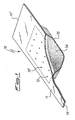
- the dispenser 10 is comprised of a container inside which the composition of the invention is present.
- the container is formed by joining an upper portion 11 and a lower portion 12.
- the two portions are preferably made of metal, and joined to each other, for example, by means of spot welding.
- the lower portion is provided with a cavity in its central area (e.g. obtained by cold pressing), inside which a composition of the invention is accommodated, whereas the upper portion is provided with a plurality of apertures 13, 13', ... for the outflow of magnesium vapors.
- the rectangular area delimited by the broken line corresponds to the cavity of portion 12.
- the mixture of the invention may be present in the cavity of portion 12 in form of powders, as shown in the drawing, wherein the composition is illustrated as element 14. Alternatively it is possible, starting from the powders, to form pills and fill the cavity with these.
- the dispenser 10 is provided with two extended ends 15 and 15' that are particularly adapted for the connection to electrical power terminals for heating the dispenser by direct flow of current.
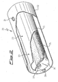
- FIG. 2 Another preferred embodiment of magnesium dispenser, particularly for use when it is desired that the dispenser is able to release large amounts of the metal, is disclosed in patent application WO 2006/057021 in the applicant's name.
- This dispenser is shown in a broken view in Fig. 2 and it is formed of a container and a shield, coaxial and having a cylindrical shape.
- the dispenser 20 is comprised of container 21 and shield 22.
- the container 21 is provided with apertures 23 (the dispenser of the drawing has three apertures, one of which is hidden by shield 22, but the container could be provided with one, two or more than three apertures).
- the shield 22 is provided with apertures 24 (only one shown) in correspondence to apertures 23 on the container.
- apertures 23 and 24 are illustrated as having a circular shape, but they could also have other shapes, e.g. elongated slits.
- the magnesium-copper composition 25 is provided, shown in the form of loose powders (but it could be in the form of pills).
- the container 21 is closed at the ends by lateral walls 26, which may be welded to the main cylindrical wall, or be in the form of "caps" inserted in said cylindrical wall.
- elements 27 are generally provided (illustrated in the drawing as simple protrusions of the wall) for the connection to electrical power supply terminals (not shown).
- the container 21 and the shield 22 are kept at a desired distance by means of thermally insulating spacers 28, generally ceramic, for example three for each end of the system and arranged in an axial symmetry at 120° from each other (only one of these spacers is shown in Fig. 2 ).
- the shield in turn, may have or be connected to lateral walls (not shown in the drawing), which are not in contact with the container, elements 27 or electrical feedthroughs (not shown as well), but arriving as close as possible to these ones: these lateral walls have the purpose of avoiding the leakage of relevant amounts of magnesium vapors from the dispenser sides, but at the same time must not be in contact with (and the less fixed to) the inner container or the electrical feedthroughs in order to enable the free mutual movement of the latter parts upon possible thermal expansions.
- the powders of Mg-Cu composition either used in the loose form or in the form of pills, generally have a grain size lower than 1 mm and preferably lower than 500 ⁇ m. Even more preferably the grain size is comprised between about 10 and 128 ⁇ m. Powders having grain size lower than 10 ⁇ m are generally difficult to treat during manufacturing and to hold within the dispenser.
- a composition for the use according to the invention is prepared by introducing a mixture comprised of 19.8 g of magnesium chips and 30.2 g of copper powder into a crucible of alumina, inserting the crucible into an induction oven under an atmosphere of argon at 600 hectoPascal (hPa), heating the oven until the melting of the mixture occurs (the resulting melt is observed through a window of the oven), maintaining the oven at this temperature for 5 minutes, letting the melt cool to room temperature and finally grinding the obtained ingot in a squeeze-type mill.
- the powder so obtained is sieved, recovering the fraction having a grain size lower than 128 ⁇ m.
- the content of magnesium of this powder is equal to 39.6% by weight.
- a dispenser of the type shown in Fig. 2 comprised of a container having an external diameter of 28.4 mm, a length of 10 cm and two circular holes (apertures 23 in Fig. 2 ), and of a shield having an inner diameter of 36 mm and a length of 10 cm. Both the container and the shield are made of AISI 304 L steel.
- the dispenser so arranged is inserted into a vacuum-tight test chamber, provided with feedthroughs for the electrical supply of the dispenser (by means of contacts such as those 27 of Fig. 2 located on container 21) and with one aperture for the connection to a vacuum system.
- a sample carrier located above the magnesium dispenser at a distance of 36 cm and close to the sample carrier a quartz crystal microbalance (QCM), which, as it is known, is used in the art in order to measure the growth rate of thin films, by exploiting the variation of vibration frequency of the crystal as a function of the weight of material deposited thereon.
- QCM quartz crystal microbalance
- the QCM is connected to the power supply system of the dispenser via a computer, in order to automatically adjust the current supplied to the system and thus its temperature, depending on the desired deposition rate of magnesium.
- a quartz glass having a square shape with a surface of about 30 cm 2 is fixed, oriented so that one face thereof is arranged directly above the dispenser and perpendicular to the direction joining the latter to the glass.
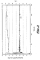
- the chamber is evacuated and when the pressure reaches the value of 10 -6 hPa the magnesium evaporation test is started by heating the container by current passage and setting the computer controlling the power supply system in order to have a growth rate of the magnesium deposit equal to 0,3 ⁇ per second ( ⁇ /s). The test is interrupted after 25 hours.
- curve DR1 relates to the growth rate of the magnesium deposit measured in ⁇ /s (the scale is set forth on the vertical axis on the left of the drawing), while curve C1 relates to the trend of the current value during the test, measured in ampere (the scale is set forth on the vertical axis on the right of the drawing).
- the deposit formed on the glass is subject to a chemical analysis via ICP, which shows only the presence of magnesium.
- Example 1 The test of Example 1 is repeated, but melting in this case a mixture formed oaf 41.3 g of magnesium chips and 32.4 g of aluminum powder, obtaining, after grinding, a powder of a percentage composition by weight of 56.04% magnesium - 43.96% aluminum.
- the dispenser is loaded with 9.06 g of this powder.
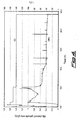
- This dispenser is introduced into the chamber used for Example 1, with the same experimental set-up, but in this case it is not possible to have a totally automatic control of the test based on the feedback current controlled by the growth rate of the deposit, due to the discontinuities and the frequent jumps of this rate. Consequently, the evaporation test is carried out by manually adjusting the supply current. Also in this case the test is interrupted after 25 hours. The results of the evaporation test are shown in Fig. 4 . Curve DR2 represents the deposition rate of magnesium, while curve C2 represents the trend of the current during the test.
- the deposit formed on the glass is subject to a chemical analysis via ICP, which shows that the deposit of magnesium contains 0.2% by weight of aluminum.
- Another magnesium evaporation test is carried out from a composition for the use according to the invention.
- a top-open crucible made of boron nitride is employed (C5 series number crucible inserted into a CH12 series heater of R. D. Mathis Company), containing 9 g of the same powders of Mg-Cu composition employed in Example 1.
- the test is carried out in the same chamber of test 1.
- the evaporation rate of magnesium is shown in Fig. 5 as curve DR3 (curve C3 shows the trend of the current during the test).
- Example 3 The test of Example 3 is repeated, but using 9 g of the same powders of Mg-Al composition as used in Example 2.
- the evaporation rate of magnesium is shown in Fig. 5 , as curve DR4 (curve C4 shows the current trend during the test). Also in this case it is not possible to have a totally automatic control of the test based on the feedback current controlled by the growth rate of the deposit, due to the discontinuities and the frequent jumps of this rate, and the evaporation test is carried out by manually adjusting the supply current, interrupting it after 30 hours.
- a magnesium-copper composition allows to have a controlled evaporation at a constant rate, thus making it possible to automatically control the evaporation at a constant growth rate of the magnesium deposit.
- Example 1 shows that the resulting deposit of magnesium is free from impurities.
- curves DR2 in Fig. 4 and DR4 in Fig. 5 show that in case of a magnesium-aluminum composition of the prior art, the evaporation characteristics are less controlled, thus not enabling the process automation in function of a predefined growth rate of the metal deposit.
- Example 2 also shows that the same deposit is less pure, containing traces of aluminum.
Applications Claiming Priority (2)
| Application Number | Priority Date | Filing Date | Title |
|---|---|---|---|
| IT000444A ITMI20060444A1 (it) | 2006-03-13 | 2006-03-13 | Uso di composizioni magnesio-rame per l'evaporazione di magnesio e dispensatori di magnesio |
| PCT/IT2007/000181 WO2007105252A1 (en) | 2006-03-13 | 2007-03-12 | Use of magnesium-copper compositions for the evaporation of magnesium and magnesium dispensers |
Publications (2)
| Publication Number | Publication Date |
|---|---|
| EP1996743A1 EP1996743A1 (en) | 2008-12-03 |
| EP1996743B1 true EP1996743B1 (en) | 2010-05-12 |
Family
ID=39877970
Family Applications (1)
| Application Number | Title | Priority Date | Filing Date |
|---|---|---|---|
| EP07736686A Active EP1996743B1 (en) | 2006-03-13 | 2007-03-12 | Use of magnesium-copper compositions for the evaporation of magnesium |
Country Status (11)
| Country | Link |
|---|---|
| US (1) | US8029597B2 (it) |
| EP (1) | EP1996743B1 (it) |
| JP (1) | JP5118689B2 (it) |
| KR (1) | KR101382538B1 (it) |
| CN (1) | CN101448970B (it) |
| AT (1) | ATE467697T1 (it) |
| DE (1) | DE602007006443D1 (it) |
| ES (1) | ES2343337T3 (it) |
| IT (1) | ITMI20060444A1 (it) |
| TW (1) | TWI397594B (it) |
| WO (1) | WO2007105252A1 (it) |
Families Citing this family (2)
| Publication number | Priority date | Publication date | Assignee | Title |
|---|---|---|---|---|
| ITMI20112051A1 (it) * | 2011-11-11 | 2013-05-12 | Getters Spa | Composizione organico-inorganica per il rilascio in fase vapore di metalli alcalini ed alcalino-terrosi |
| KR102056100B1 (ko) * | 2016-04-01 | 2019-12-17 | 주식회사 엘지화학 | 3d 프린팅 방법 |
Family Cites Families (19)
| Publication number | Priority date | Publication date | Assignee | Title |
|---|---|---|---|---|
| GB1182150A (en) * | 1966-12-13 | 1970-02-25 | Getters Spa | Alkali Metal Vapour Dispensers. |
| NL6913692A (it) | 1968-09-13 | 1970-03-17 | ||
| NL6913693A (it) | 1968-09-13 | 1970-03-17 | ||
| US3663121A (en) | 1969-05-24 | 1972-05-16 | Getters Spa | Generation of metal vapors |
| US4233936A (en) | 1979-05-08 | 1980-11-18 | Rca Corporation | Alkali metal dispenser |
| FR2611746B1 (fr) * | 1987-03-06 | 1989-06-30 | Centre Nat Etd Spatiales | Dispositif d'evaporation sous vide d'un metal en continu |
| JPH03170661A (ja) * | 1989-11-27 | 1991-07-24 | Kobe Steel Ltd | 昇華性金属の蒸発方法 |
| JPH08269696A (ja) * | 1995-03-28 | 1996-10-15 | Nisshin Steel Co Ltd | Mgの蒸発方法 |
| JPH08283942A (ja) * | 1995-04-14 | 1996-10-29 | Ishikawajima Harima Heavy Ind Co Ltd | 昇華性金属材料の蒸発方法 |
| ATE247372T1 (de) | 1996-09-04 | 2003-08-15 | Cambridge Display Tech Ltd | Lichtemittierende organische vorrichtungen mit verbesserter kathode |
| JPH10270171A (ja) | 1997-01-27 | 1998-10-09 | Junji Kido | 有機エレクトロルミネッセント素子 |
| ITMI20010995A1 (it) | 2001-05-15 | 2002-11-15 | Getters Spa | Dispensatori di cesio e processo per il loro uso |
| US6770502B2 (en) | 2002-04-04 | 2004-08-03 | Eastman Kodak Company | Method of manufacturing a top-emitting OLED display device with desiccant structures |
| EP1422281A1 (en) * | 2002-11-19 | 2004-05-26 | Ciba SC Holding AG | Organic electroluminescent element |
| CN100484352C (zh) * | 2003-10-02 | 2009-04-29 | 株式会社丰田自动织机 | 电致发光元件 |
| US7790890B2 (en) * | 2004-03-31 | 2010-09-07 | Konica Minolta Holdings, Inc. | Organic electroluminescence element material, organic electroluminescence element, display device and illumination device |
| NL1026214C2 (nl) | 2004-05-18 | 2005-11-21 | Otb Group Bv | Werkwijze en inrichting voor opbrengen van een actieve stof op een substraat. |
| ITMI20042279A1 (it) | 2004-11-24 | 2005-02-24 | Getters Spa | Sistema dispensatore di metalli alcalini in grado di dispensare quantita' elevate di metalli |
| JP4744415B2 (ja) | 2006-10-16 | 2011-08-10 | 中国電力株式会社 | 自動再閉路機能付き監視制御装置 |
-
2006
- 2006-03-13 IT IT000444A patent/ITMI20060444A1/it unknown
-
2007
- 2007-03-09 TW TW096108274A patent/TWI397594B/zh active
- 2007-03-12 EP EP07736686A patent/EP1996743B1/en active Active
- 2007-03-12 AT AT07736686T patent/ATE467697T1/de active
- 2007-03-12 JP JP2009500007A patent/JP5118689B2/ja active Active
- 2007-03-12 DE DE602007006443T patent/DE602007006443D1/de active Active
- 2007-03-12 US US12/282,758 patent/US8029597B2/en active Active
- 2007-03-12 ES ES07736686T patent/ES2343337T3/es active Active
- 2007-03-12 CN CN2007800088701A patent/CN101448970B/zh active Active
- 2007-03-12 WO PCT/IT2007/000181 patent/WO2007105252A1/en active Application Filing
- 2007-03-12 KR KR1020087024640A patent/KR101382538B1/ko active IP Right Grant
Also Published As
| Publication number | Publication date |
|---|---|
| TWI397594B (zh) | 2013-06-01 |
| CN101448970A (zh) | 2009-06-03 |
| US20090266201A1 (en) | 2009-10-29 |
| WO2007105252A8 (en) | 2008-10-16 |
| WO2007105252A1 (en) | 2007-09-20 |
| DE602007006443D1 (de) | 2010-06-24 |
| ES2343337T3 (es) | 2010-07-28 |
| JP5118689B2 (ja) | 2013-01-16 |
| ATE467697T1 (de) | 2010-05-15 |
| US8029597B2 (en) | 2011-10-04 |
| TW200745358A (en) | 2007-12-16 |
| EP1996743A1 (en) | 2008-12-03 |
| KR101382538B1 (ko) | 2014-04-07 |
| CN101448970B (zh) | 2011-03-09 |
| ITMI20060444A1 (it) | 2007-09-14 |
| JP2009530491A (ja) | 2009-08-27 |
| KR20080102425A (ko) | 2008-11-25 |
Similar Documents
| Publication | Publication Date | Title |
|---|---|---|
| US7935382B2 (en) | Method for making crystalline composition | |
| US8039412B2 (en) | Crystalline composition, device, and associated method | |
| US7942970B2 (en) | Apparatus for making crystalline composition | |
| KR101090614B1 (ko) | 수은 분배 조성물 및 그 제조 방법 | |
| CN102630254B (zh) | 用于硫属化物光伏应用的低熔点溅射靶及其制造方法 | |
| WO2006075998A2 (en) | Means and method for a liquid metal evaporation source with integral level sensor and external reservoir | |
| Wada | Preparation of fine metal particles by the gas evaporation method with plasma jet flame | |
| HU215491B (hu) | Keveréktöltet higanykibocsátó eszközhöz, higanykibocsátó eszköz és eljárás higanynak elektroncsövek belsejébe juttatására | |
| Chen et al. | Crystallization temperature and activation energy of rf-sputtered near-equiatomic TiNi and Ti50Ni40Cu10 thin films | |
| HU215489B (hu) | Keveréktöltet higanykibocsátó eszközhöz, higanykibocsátó eszköz és eljárás higanynak elektroncsövek belsejébe juttatására | |
| Yamada et al. | Metal carbide-carbon peritectic systems as high-temperature fixed points in thermometry | |
| CN1403617A (zh) | 含有锌元素的多组元镁基非晶态合金 | |
| EP1996743B1 (en) | Use of magnesium-copper compositions for the evaporation of magnesium | |
| Yu et al. | Ultra-high purity tungsten and its applications | |
| WO1990007021A1 (en) | Process for producing single crystal | |
| JP5392695B2 (ja) | アルミニウム金属の製造方法および製造装置 | |
| Olsen et al. | Techniques for evaporation of metals | |
| Bunshah | Vacuum evaporation-history, recent developments and applications | |
| WO2002000959A1 (en) | Cathodes for cathodic deposition of getter alloys and a process for the manufacture thereof | |
| Bozack et al. | Wettability of transition metal boride eutectic alloys to graphite | |
| RU2356964C1 (ru) | Способ производства распыляемых мишеней из литых дисилицидов тугоплавких металлов и устройство для его реализации | |
| WO2024053010A1 (ja) | 高純度三酸化二ガリウムおよびその製造方法 | |
| TW202411166A (zh) | 高純度三氧化二鎵及其製造方法 | |
| Yamaguchi et al. | Preparation of Ultrafine AlN Particles with Hexagonal Prism Shape by Reaction between Nitrogen Plasma and Molten Al–Y Alloys | |
| Sasajima et al. | Metal Carbide-Carbon Eutectic and Peritectic Fixed Points as High-Temperature Standards |
Legal Events
| Date | Code | Title | Description |
|---|---|---|---|
| PUAI | Public reference made under article 153(3) epc to a published international application that has entered the european phase |
Free format text: ORIGINAL CODE: 0009012 |
|
| 17P | Request for examination filed |
Effective date: 20081006 |
|
| AK | Designated contracting states |
Kind code of ref document: A1 Designated state(s): AT BE BG CH CY CZ DE DK EE ES FI FR GB GR HU IE IS IT LI LT LU LV MC MT NL PL PT RO SE SI SK TR |
|
| 17Q | First examination report despatched |
Effective date: 20090402 |
|
| RTI1 | Title (correction) |
Free format text: USE OF MAGNESIUM-COPPER COMPOSITIONS FOR THE EVAPORATION OF MAGNESIUM |
|
| GRAP | Despatch of communication of intention to grant a patent |
Free format text: ORIGINAL CODE: EPIDOSNIGR1 |
|
| GRAS | Grant fee paid |
Free format text: ORIGINAL CODE: EPIDOSNIGR3 |
|
| GRAA | (expected) grant |
Free format text: ORIGINAL CODE: 0009210 |
|
| AK | Designated contracting states |
Kind code of ref document: B1 Designated state(s): AT BE BG CH CY CZ DE DK EE ES FI FR GB GR HU IE IS IT LI LT LU LV MC MT NL PL PT RO SE SI SK TR |
|
| REG | Reference to a national code |
Ref country code: GB Ref legal event code: FG4D |
|
| REG | Reference to a national code |
Ref country code: CH Ref legal event code: EP |
|
| REG | Reference to a national code |
Ref country code: IE Ref legal event code: FG4D |
|
| REF | Corresponds to: |
Ref document number: 602007006443 Country of ref document: DE Date of ref document: 20100624 Kind code of ref document: P |
|
| REG | Reference to a national code |
Ref country code: NL Ref legal event code: T3 |
|
| REG | Reference to a national code |
Ref country code: ES Ref legal event code: FG2A Ref document number: 2343337 Country of ref document: ES Kind code of ref document: T3 |
|
| LTIE | Lt: invalidation of european patent or patent extension |
Effective date: 20100512 |
|
| PG25 | Lapsed in a contracting state [announced via postgrant information from national office to epo] |
Ref country code: SE Free format text: LAPSE BECAUSE OF FAILURE TO SUBMIT A TRANSLATION OF THE DESCRIPTION OR TO PAY THE FEE WITHIN THE PRESCRIBED TIME-LIMIT Effective date: 20100512 Ref country code: LT Free format text: LAPSE BECAUSE OF FAILURE TO SUBMIT A TRANSLATION OF THE DESCRIPTION OR TO PAY THE FEE WITHIN THE PRESCRIBED TIME-LIMIT Effective date: 20100512 |
|
| PG25 | Lapsed in a contracting state [announced via postgrant information from national office to epo] |
Ref country code: LV Free format text: LAPSE BECAUSE OF FAILURE TO SUBMIT A TRANSLATION OF THE DESCRIPTION OR TO PAY THE FEE WITHIN THE PRESCRIBED TIME-LIMIT Effective date: 20100512 Ref country code: FI Free format text: LAPSE BECAUSE OF FAILURE TO SUBMIT A TRANSLATION OF THE DESCRIPTION OR TO PAY THE FEE WITHIN THE PRESCRIBED TIME-LIMIT Effective date: 20100512 Ref country code: SI Free format text: LAPSE BECAUSE OF FAILURE TO SUBMIT A TRANSLATION OF THE DESCRIPTION OR TO PAY THE FEE WITHIN THE PRESCRIBED TIME-LIMIT Effective date: 20100512 Ref country code: IS Free format text: LAPSE BECAUSE OF FAILURE TO SUBMIT A TRANSLATION OF THE DESCRIPTION OR TO PAY THE FEE WITHIN THE PRESCRIBED TIME-LIMIT Effective date: 20100912 |
|
| PG25 | Lapsed in a contracting state [announced via postgrant information from national office to epo] |
Ref country code: CY Free format text: LAPSE BECAUSE OF FAILURE TO SUBMIT A TRANSLATION OF THE DESCRIPTION OR TO PAY THE FEE WITHIN THE PRESCRIBED TIME-LIMIT Effective date: 20100602 Ref country code: PL Free format text: LAPSE BECAUSE OF FAILURE TO SUBMIT A TRANSLATION OF THE DESCRIPTION OR TO PAY THE FEE WITHIN THE PRESCRIBED TIME-LIMIT Effective date: 20100512 |
|
| PG25 | Lapsed in a contracting state [announced via postgrant information from national office to epo] |
Ref country code: EE Free format text: LAPSE BECAUSE OF FAILURE TO SUBMIT A TRANSLATION OF THE DESCRIPTION OR TO PAY THE FEE WITHIN THE PRESCRIBED TIME-LIMIT Effective date: 20100512 Ref country code: DK Free format text: LAPSE BECAUSE OF FAILURE TO SUBMIT A TRANSLATION OF THE DESCRIPTION OR TO PAY THE FEE WITHIN THE PRESCRIBED TIME-LIMIT Effective date: 20100512 Ref country code: PT Free format text: LAPSE BECAUSE OF FAILURE TO SUBMIT A TRANSLATION OF THE DESCRIPTION OR TO PAY THE FEE WITHIN THE PRESCRIBED TIME-LIMIT Effective date: 20100913 |
|
| PG25 | Lapsed in a contracting state [announced via postgrant information from national office to epo] |
Ref country code: BE Free format text: LAPSE BECAUSE OF FAILURE TO SUBMIT A TRANSLATION OF THE DESCRIPTION OR TO PAY THE FEE WITHIN THE PRESCRIBED TIME-LIMIT Effective date: 20100512 Ref country code: RO Free format text: LAPSE BECAUSE OF FAILURE TO SUBMIT A TRANSLATION OF THE DESCRIPTION OR TO PAY THE FEE WITHIN THE PRESCRIBED TIME-LIMIT Effective date: 20100512 Ref country code: CZ Free format text: LAPSE BECAUSE OF FAILURE TO SUBMIT A TRANSLATION OF THE DESCRIPTION OR TO PAY THE FEE WITHIN THE PRESCRIBED TIME-LIMIT Effective date: 20100512 Ref country code: SK Free format text: LAPSE BECAUSE OF FAILURE TO SUBMIT A TRANSLATION OF THE DESCRIPTION OR TO PAY THE FEE WITHIN THE PRESCRIBED TIME-LIMIT Effective date: 20100512 |
|
| PLBE | No opposition filed within time limit |
Free format text: ORIGINAL CODE: 0009261 |
|
| STAA | Information on the status of an ep patent application or granted ep patent |
Free format text: STATUS: NO OPPOSITION FILED WITHIN TIME LIMIT |
|
| 26N | No opposition filed |
Effective date: 20110215 |
|
| PG25 | Lapsed in a contracting state [announced via postgrant information from national office to epo] |
Ref country code: GR Free format text: LAPSE BECAUSE OF FAILURE TO SUBMIT A TRANSLATION OF THE DESCRIPTION OR TO PAY THE FEE WITHIN THE PRESCRIBED TIME-LIMIT Effective date: 20100813 |
|
| REG | Reference to a national code |
Ref country code: DE Ref legal event code: R097 Ref document number: 602007006443 Country of ref document: DE Effective date: 20110214 |
|
| PG25 | Lapsed in a contracting state [announced via postgrant information from national office to epo] |
Ref country code: MC Free format text: LAPSE BECAUSE OF NON-PAYMENT OF DUE FEES Effective date: 20110331 |
|
| REG | Reference to a national code |
Ref country code: CH Ref legal event code: PL |
|
| GBPC | Gb: european patent ceased through non-payment of renewal fee |
Effective date: 20110312 |
|
| REG | Reference to a national code |
Ref country code: FR Ref legal event code: ST Effective date: 20111130 |
|
| PG25 | Lapsed in a contracting state [announced via postgrant information from national office to epo] |
Ref country code: MT Free format text: LAPSE BECAUSE OF FAILURE TO SUBMIT A TRANSLATION OF THE DESCRIPTION OR TO PAY THE FEE WITHIN THE PRESCRIBED TIME-LIMIT Effective date: 20100512 |
|
| REG | Reference to a national code |
Ref country code: IE Ref legal event code: MM4A |
|
| PG25 | Lapsed in a contracting state [announced via postgrant information from national office to epo] |
Ref country code: IE Free format text: LAPSE BECAUSE OF NON-PAYMENT OF DUE FEES Effective date: 20110312 Ref country code: LI Free format text: LAPSE BECAUSE OF NON-PAYMENT OF DUE FEES Effective date: 20110331 Ref country code: FR Free format text: LAPSE BECAUSE OF NON-PAYMENT OF DUE FEES Effective date: 20110331 Ref country code: CH Free format text: LAPSE BECAUSE OF NON-PAYMENT OF DUE FEES Effective date: 20110331 |
|
| PG25 | Lapsed in a contracting state [announced via postgrant information from national office to epo] |
Ref country code: GB Free format text: LAPSE BECAUSE OF NON-PAYMENT OF DUE FEES Effective date: 20110312 |
|
| REG | Reference to a national code |
Ref country code: ES Ref legal event code: FD2A Effective date: 20120423 |
|
| PG25 | Lapsed in a contracting state [announced via postgrant information from national office to epo] |
Ref country code: ES Free format text: LAPSE BECAUSE OF NON-PAYMENT OF DUE FEES Effective date: 20110313 |
|
| PG25 | Lapsed in a contracting state [announced via postgrant information from national office to epo] |
Ref country code: LU Free format text: LAPSE BECAUSE OF NON-PAYMENT OF DUE FEES Effective date: 20110312 |
|
| PG25 | Lapsed in a contracting state [announced via postgrant information from national office to epo] |
Ref country code: BG Free format text: LAPSE BECAUSE OF FAILURE TO SUBMIT A TRANSLATION OF THE DESCRIPTION OR TO PAY THE FEE WITHIN THE PRESCRIBED TIME-LIMIT Effective date: 20100812 Ref country code: TR Free format text: LAPSE BECAUSE OF FAILURE TO SUBMIT A TRANSLATION OF THE DESCRIPTION OR TO PAY THE FEE WITHIN THE PRESCRIBED TIME-LIMIT Effective date: 20100512 |
|
| PG25 | Lapsed in a contracting state [announced via postgrant information from national office to epo] |
Ref country code: HU Free format text: LAPSE BECAUSE OF FAILURE TO SUBMIT A TRANSLATION OF THE DESCRIPTION OR TO PAY THE FEE WITHIN THE PRESCRIBED TIME-LIMIT Effective date: 20100512 |
|
| PGFP | Annual fee paid to national office [announced via postgrant information from national office to epo] |
Ref country code: AT Payment date: 20230221 Year of fee payment: 17 |
|
| PGFP | Annual fee paid to national office [announced via postgrant information from national office to epo] |
Ref country code: IT Payment date: 20230321 Year of fee payment: 17 |
|
| P01 | Opt-out of the competence of the unified patent court (upc) registered |
Effective date: 20230515 |
|
| PGFP | Annual fee paid to national office [announced via postgrant information from national office to epo] |
Ref country code: NL Payment date: 20240326 Year of fee payment: 18 |
|
| PGFP | Annual fee paid to national office [announced via postgrant information from national office to epo] |
Ref country code: AT Payment date: 20240221 Year of fee payment: 18 |
|
| PGFP | Annual fee paid to national office [announced via postgrant information from national office to epo] |
Ref country code: DE Payment date: 20240327 Year of fee payment: 18 |