EP1995742B1 - Transformer core - Google Patents
Transformer core Download PDFInfo
- Publication number
- EP1995742B1 EP1995742B1 EP08075203.3A EP08075203A EP1995742B1 EP 1995742 B1 EP1995742 B1 EP 1995742B1 EP 08075203 A EP08075203 A EP 08075203A EP 1995742 B1 EP1995742 B1 EP 1995742B1
- Authority
- EP
- European Patent Office
- Prior art keywords
- core
- transformer
- sub
- contact faces
- parts
- Prior art date
- Legal status (The legal status is an assumption and is not a legal conclusion. Google has not performed a legal analysis and makes no representation as to the accuracy of the status listed.)
- Active
Links
Images


Classifications
-
- H—ELECTRICITY
- H01—ELECTRIC ELEMENTS
- H01F—MAGNETS; INDUCTANCES; TRANSFORMERS; SELECTION OF MATERIALS FOR THEIR MAGNETIC PROPERTIES
- H01F27/00—Details of transformers or inductances, in general
- H01F27/24—Magnetic cores
- H01F27/245—Magnetic cores made from sheets, e.g. grain-oriented
-
- G—PHYSICS
- G01—MEASURING; TESTING
- G01F—MEASURING VOLUME, VOLUME FLOW, MASS FLOW OR LIQUID LEVEL; METERING BY VOLUME
- G01F1/00—Measuring the volume flow or mass flow of fluid or fluent solid material wherein the fluid passes through a meter in a continuous flow
- G01F1/76—Devices for measuring mass flow of a fluid or a fluent solid material
- G01F1/78—Direct mass flowmeters
- G01F1/80—Direct mass flowmeters operating by measuring pressure, force, momentum, or frequency of a fluid flow to which a rotational movement has been imparted
- G01F1/84—Coriolis or gyroscopic mass flowmeters
- G01F1/8409—Coriolis or gyroscopic mass flowmeters constructional details
- G01F1/8413—Coriolis or gyroscopic mass flowmeters constructional details means for influencing the flowmeter's motional or vibrational behaviour, e.g., conduit support or fixing means, or conduit attachments
-
- G—PHYSICS
- G01—MEASURING; TESTING
- G01F—MEASURING VOLUME, VOLUME FLOW, MASS FLOW OR LIQUID LEVEL; METERING BY VOLUME
- G01F1/00—Measuring the volume flow or mass flow of fluid or fluent solid material wherein the fluid passes through a meter in a continuous flow
- G01F1/76—Devices for measuring mass flow of a fluid or a fluent solid material
- G01F1/78—Direct mass flowmeters
- G01F1/80—Direct mass flowmeters operating by measuring pressure, force, momentum, or frequency of a fluid flow to which a rotational movement has been imparted
- G01F1/84—Coriolis or gyroscopic mass flowmeters
- G01F1/8409—Coriolis or gyroscopic mass flowmeters constructional details
- G01F1/8422—Coriolis or gyroscopic mass flowmeters constructional details exciters
-
- G—PHYSICS
- G01—MEASURING; TESTING
- G01F—MEASURING VOLUME, VOLUME FLOW, MASS FLOW OR LIQUID LEVEL; METERING BY VOLUME
- G01F1/00—Measuring the volume flow or mass flow of fluid or fluent solid material wherein the fluid passes through a meter in a continuous flow
- G01F1/76—Devices for measuring mass flow of a fluid or a fluent solid material
- G01F1/78—Direct mass flowmeters
- G01F1/80—Direct mass flowmeters operating by measuring pressure, force, momentum, or frequency of a fluid flow to which a rotational movement has been imparted
- G01F1/84—Coriolis or gyroscopic mass flowmeters
- G01F1/845—Coriolis or gyroscopic mass flowmeters arrangements of measuring means, e.g., of measuring conduits
- G01F1/8468—Coriolis or gyroscopic mass flowmeters arrangements of measuring means, e.g., of measuring conduits vibrating measuring conduits
- G01F1/8481—Coriolis or gyroscopic mass flowmeters arrangements of measuring means, e.g., of measuring conduits vibrating measuring conduits having loop-shaped measuring conduits, e.g. the measuring conduits form a loop with a crossing point
- G01F1/8486—Coriolis or gyroscopic mass flowmeters arrangements of measuring means, e.g., of measuring conduits vibrating measuring conduits having loop-shaped measuring conduits, e.g. the measuring conduits form a loop with a crossing point with multiple measuring conduits
-
- H—ELECTRICITY
- H01—ELECTRIC ELEMENTS
- H01F—MAGNETS; INDUCTANCES; TRANSFORMERS; SELECTION OF MATERIALS FOR THEIR MAGNETIC PROPERTIES
- H01F3/00—Cores, Yokes, or armatures
- H01F3/02—Cores, Yokes, or armatures made from sheets
-
- H—ELECTRICITY
- H01—ELECTRIC ELEMENTS
- H01F—MAGNETS; INDUCTANCES; TRANSFORMERS; SELECTION OF MATERIALS FOR THEIR MAGNETIC PROPERTIES
- H01F3/00—Cores, Yokes, or armatures
- H01F3/10—Composite arrangements of magnetic circuits
- H01F3/14—Constrictions; Gaps, e.g. air-gaps
Definitions
- the invention relates to a transformer comprising a core, which core comprises a stack of a plurality of plate-shaped core parts (or core laminations) of a magnetically permeable material which each consist of a first and second sub-part that together enclose at least one opening.
- transformer core Building-up a transformer core from stacked plates of a soft-magnetic (or magnetically permeable) material is a usual technique for manufacturing transformers.
- the object is to minimize stray fields within the transformer core, or to achieve that the field lines run round in parallel and eddy currents are minimized.
- Transformer cores and methods for their manufacturing are known from DE 7342490 and GB 680,577 .
- the present method of building a transformer is to stack U-shaped and I-shaped plate parts in alternation.
- the U-parts are inserted into an electric coil from alternating sides during the assembling process.
- a main disadvantage of the present method is that the parts are never perfectly joined together, so that an air gap arises between the mutually facing surfaces at the end of the U and the side of the I. Only half the diameter is effectively available in that location as a result. This diameter determines the saturation flux through the entire transformer core.
- Another conventional technique is to stack the U- and I-plates all in the same manner, to grind the contact faces, and finally to join these together with fastening means. This is more labor-intensive and accordingly more expensive.
- the transformer comprising a core according to the invention is for this purpose characterized according to claim 1.
- each core part bear on each other with first and second contact faces that lie on either side of the opening and that extend obliquely relative to the centerline of the core plate.
- An embodiment of the invention relates to a so-termed oblique division of the core laminations into two sub-parts, the core laminations being stacked alternately.
- the two sub-parts must be contraform, i.e. having mutually matching shapes. They may be identical or mutually different.
- a first advantage of an oblique division is: a larger minimum diameter.
- Fig. 2b shows a line B-B representing a division along a perpendicular diameter and a line C-C representing a division along an oblique diameter.
- the diameter available for conducting the flux is in fact larger by approximately a factor of ⁇ 2 (for an angle of division of 45°) than in the conventional construction with a perpendicular division of the core laminations.
- a second advantage of an oblique division is: self-centering.
- the contact faces situated on either side of the opening are oriented such that the first and the second sub-part are self-centering when being fitted together.
- the oblique division renders self-centering during joining together of the two core halves possible ( Fig. 4 ).
- a third advantage of an oblique division is: easier (dis-)assembly.
- the two halves of the transformer core each consisting of a pack of alternately stacked sub-parts that are fastened to one another (for example by means of laser welding), can be pressed into one another and pulled apart again thanks to the oblique contact faces.
- This is convenient, for example, during mounting of the transformer core in a Coriolis flowmeter instrument, wherein the Coriolis tube is to be passed through the opening in the transformer core, because in that case the upper core half need not be mounted until after the vulnerable Coriolis tube has been placed in its housing.
- the two halves then fit clampingly into one another without additional fastening means.
- At least the first core part is U-shaped with two legs that each terminate in a contact face, said contact faces extending obliquely to the cross-section of the legs.
- oblique contact faces are used that are at an angle of between 30° and 60°, in particular 45°, to the perpendicular ('smallest') diameter.
- the principle of oblique division is also applicable to a transformer core with two openings, also denoted a double-loop core, for current or voltage conversion, having core laminations usually consisting of E-shaped and I-shaped plates (sub-parts), cf. Fig. 6 .
- the complementary contact faces of two adjoining core plates do not lie perpendicularly above one another.
- the complementary contact faces of adjoining core plates lie in different planes. These planes may or may not cross each other in the area of the core plates, or they may be parallel, for example.
- a crossing design has the advantage that it results in a shorter clamping length of the core halves, which are accordingly easier to move into and out of each other, or can be more readily disassembled.
- the non-crossing design leads to a greater clamping length, which may be desirable in itself, subject to the dimensions or the operating conditions.
- the invention accordingly also relates to a Coriolis flowmeter with a Coriolis tube, characterized in that the Coriolis tube is passed through the opening of at least one transformer core according to the invention, and in that a primary coil is wound around a portion of each core so as to induce a current in the Coriolis tube when the coil is energized.
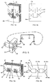
- Figs. 1a, b, c show the construction of a conventional transformer core (21) consisting of a stack of core laminations 22, 23 each comprising a U-shaped (U) and an I-shaped (I) sub-part, which sub-parts enclose a core opening 24 and bear on one another with contact faces that are perpendicular to two mutually facing walls of the core opening 24.
- a conventional transformer core (21) consisting of a stack of core laminations 22, 23 each comprising a U-shaped (U) and an I-shaped (I) sub-part, which sub-parts enclose a core opening 24 and bear on one another with contact faces that are perpendicular to two mutually facing walls of the core opening 24.
- Figs. 2a, b, c show the construction of a transformer core according to the invention.
- Fig. 2a shows a first pair of two planar sub-parts 27, 28 of magnetically permeable material that are placed against each other and that together constitute a (rectangular, in this case square) core lamination 25 with a central (rectangular, in this case square) opening 26.
- the one sub-part 27 comprises three of the walls (a, b, c) of the opening, two of which (a and c) lie opposite one another, and oblique contact faces 32, 33 that extend from corners of the opening 26 to two mutually opposed side walls 35, 36 of the core lamination 25.
- the other sub-part 28 comprises the fourth wall (d) of the opening and has oblique contact faces 32a, 33a that extend from the corners of the fourth wall (d) of the opening 26 to said side walls 35, 36 of the core and that bear on the contact faces 32, 33 of the first sub-part 28.
- a second pair of planar sub-parts 27a, 28a identical to the first pair and together forming a core lamination 25a is placed against the first pair parallel thereto but rotated through 180° with respect thereto ( Fig. 2b ). It is to be noted in this connection that the laminations are usually mutually separated by an electrically insulating (paint) coating.
- a number of first and second pairs in this alternating arrangement together form a transformer core 29 with two parallel 'legs' 30, 31 ( Fig. 2c ). After assembly one leg 31 of the core 29 is passed through an electric winding or coil (32 in Fig. 3 ).
- the field lines in the magnet's core cross the air gaps formed between the contact faces at an oblique angle owing to the oblique orientation of the contact faces relative to the cross-section of the core part of which they form part.
- the idea of making the field lines cross at an oblique angle provides an improvement in comparison with the conventional transformer core, where the field lines cross the air gap formed between the contact surfaces perpendicularly ( Fig. 1 ).
- An optimum angle would be an infinitely acute angle wherein the individual sub-parts interlock as pointed fingers. This, however, is not practical for reasons of manufacturing and assembling technology, which is why an angle of 45° was chosen, or more in general, an angle between 30° and 60°.
- U- and I-plates are stacked in alternation in conventional transformer cores.
- the next adjoining plate is a U
- the following plate again has an air gap in this location; i.e. half of the plates are part of a U here while the other half of the core consists of air gaps.
- the field lines will want to use the adjoining solid pad as much as possible adjacent the air gap, so saturation will occur locally in the core material and no more field can pass through the soft iron.
- the remainder of the field lines will then cross via the air gap, which has a high magnetic resistance. This transition, accordingly, is responsible for the performance of the transformer core.
- a transformer core according to the invention, however, core laminations are used with two sub-parts comprising contact faces that are not perpendicular (as shown in Fig. 1 ), but that are oblique.
- ⁇ 2 times more material is available at the area of an air gap where two sub-parts of a core lamination meet at an angle of 45°, which improves the efficiency or performance of the transformer core.
- Fig. 4a is a perspective view showing how a transformer core according to the invention is assembled.
- sub-parts 27a and 28 having contact faces that are oblique relative to the centerline C of the kind described with reference to Fig. 2 are stacked in alternation and fastened together so as to form a pack (upper pack), see also the diagrammatic front elevation of Fig. 4b .
- sub-parts 27 and 28a of the kind described with reference to Fig. 2 are stacked in alternation and fastened together so as to form a pack (lower pack), see also the diagrammatic front elevation of Fig. 4b .
- the upper pack and the lower pack are pressed together in the direction of the arrow in Fig. 4b .
- the sub-parts 27 and 28 and the sub-parts 27a and 28a are self-centering during this.
- the contact faces of mutually adjoining core plates, each consisting of two sub-parts will cross two by two.
- a portion of a Coriolis tube 33 extends through the central opening 34 of the core 35 in this case.
- Said core is a transformer core with sub-parts having oblique contact faces according to the invention.
- An electric coil 36 forming a primary winding is wound on a leg of the core 35 and is connected to an AC source 37 for inducing an AC current in the Coriolis tube 33 which forms a secondary winding ( Fig. 5 ).
- the Coriolis tube 33 here is a looped tube having a U-shape that is clamped in in two locations 38, 39.
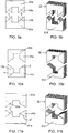
- Fig. 6a is a perspective view and Fig. 6b a diagrammatic front elevation of a modified version of a conventional E-I core with two openings 41, 42 and a central leg 43.
- Many transformers are constructed in this manner, with both the primary and the secondary windings being wound around the central leg of the E. These winding are often wound on a separate (square) coil former.
- the individual plates (sub-parts) for the E and the I are then laid alternately up and down in the coil former such that the transformer is created.
- three pairs of oblique contact faces 44, 44a; 45, 45a; and 46, 46a between the E and the I are used.
- the core 40 shown in Fig. 6a is suitable for use as a transformer core in general and for generating current in Coriolis sensing tubes, for example in that a primary electric coil is arranged around the central leg 43 of the core while the Coriolis tube forms a closed secondary loop (not shown) that is passed through both openings 41, 42.
- This has the advantage, in addition to the improved efficiency, inter alia that the core 40 can be readily disassembled for the purpose of removing windings and possibly modifying them.
- Fig. 7 shows two alternative methods of dividing the laminations of a transformer core plate along oblique contact faces.
- Fig. 7a shows a division along oblique surfaces from the centers of the sides of the core opening 52 to the mutually opposed sides 53, 54 of the core plate or core lamination 55, resulting in two identical sub-parts 56, 57
- Fig. 7b shows a division along oblique surfaces from the corners of the core opening 58 to two corner points of the core plate or core lamination 59, resulting in a U-shaped sub-part 60 and an I-shaped sub-part 61.
- Fig. 8 shows a special embodiment (to which the invention is not limited) of a flowmeter 1 of the Coriolis type with a looped sensing tube 2 bent into a U-shape that follows a substantially closed path (a substantially full turn).
- the looped sensing tube 2 comprises two parallel lateral tube portions 2c, 2d that are connected at one end to a first transverse tube portion 2e and at the other end to two second transverse tube portions 2a and 2b.
- the latter are connected to a - flexible - feed tube 3 and a - flexible - discharge tube 4 for a fluid medium at the side opposite to the respective sides where they are connected to the lateral tubes 2c, 2d.
- the loop 2 and the feed and discharge tubes 3, 4 are part of the same tube.
- the tube 2 in its entirety is bent into a rectangular shape with rounded corners so as to make this shape possible at all.
- the feed tube 3 is connected via a feed and discharge block 20 to a feed line 6, and the discharge tube 4 is thus connected to a discharge line 7.
- the feed and discharge tubes 3, 4 in this embodiment extend within the loop 2 and are fastened to a frame 13 by fastening means 12.
- the flexible feed and discharge tubes 3, 4 do not form part of the loop shape of the sensing tube 2 but provide a flexible fastening of the loop 2 to the frame 13.
- the loop 2 may accordingly be regarded as being flexibly suspended by means of the feed and discharge tubes.
- the loop 2 and the feed and discharge tubes 3, 4 may advantageously be manufactured from one piece of tubing.
- This may be, for example, a stainless steel tube with an outer diameter of approximately 0.7 mm and a wall thickness of approximately 0.1 mm.
- the outer diameter of the tube will generally be smaller than 1 mm and the wall thickness 0.2 mm or less.
- the tubes 3 and 4 which extend close together on either side of and symmetrically with respect to the main axis of symmetry S of the tube 2, are fastened to the fastening means 12, for example by means of clamping, soldering or welding, said means in their turn being fastened to the frame 13.
- the tubes 3, 4 may be directly fastened to the frame 13.
- Excitation means for causing the loop 2 to rotate about the main axis of symmetry (in this case the primary or excitation axis of rotation) in the construction of Fig. 8 comprise a magnetic yoke 8 with two air gaps 9 and 10 that is fastened to the frame 13 and is provided with a permanent magnet 19, portions 2a and 2b (denoted the second transverse tubes above) of the looped tube extending through said air gaps, and comprise means for introducing an electric current into the tube 2. These are means for generating current in the tube 2 by means of induction in Fig. 8 .
- the permanently magnetic yoke 8 has two upper yoke parts 8a and 8a' that are separated from a lower yoke part 8b by the air gaps 9 and 10.
- the permanent magnet 19 is arranged between the yoke parts 8a and 8a' with its one (North) pole facing the yoke part 8a and its other (South) pole facing the yoke part 8a'.
- transformer cores 17, 17a which are provided with respective electric coils 18a, 18b and through which the respective lateral tube portions 2c and 2d extend.
- the transformer cores are of the type according to the invention having sub-parts with oblique contact faces.
- the coils 18a, 18b may be wound on the inner sides of the transformer cores, as shown, or on one of the other sides.
- the magnetic fields generated in the gaps 9 and 10 of the permanently magnetic yoke 8, which fields are transverse to the current direction and mutually oppositely directed, in combination with an (AC) current induced in the tube 2 result in a torque being applied to the tube owing to which said tube starts to rotate (in an oscillating manner) about the axis of rotation (vibration in the so-termed twist mode).
- a Coriolis effect sensor which comprises a first sensor 11 a arranged adjacent the tube portion 2e and a second sensor 11 b.
- the first and the second sensor are arranged symmetrically on either side of the excitation axis of rotation close to the point of intersection thereof with the tube portion 2e.
- a third sensor 11c may serve for correction purposes.
- the sensors may be, for example, of an electromagnetic, inductive, capacitive, or ultrasonic type.
- optical sensors were chosen.
- the optical sensors used here were so-termed optoelectronic sensors 11a, 11 b, 11 c which each comprise a U-shaped housing fastened to the frame 13 and comprising a light source (for example an LED) in one leg of the U and in the other leg a light-measuring cell (for example a phototransistor) arranged opposite the light source.
- the tube portion 2e, or a vane fastened thereto, can move between the sensors 11 a, 11 b (and 11c, if present) on the legs of the U-shaped sensor housing and intercept more or less light of the light source.
- Figs. 1 to 7 all show embodiments that are symmetrical relative to the centerline in the plane of the core plate parallel to the direction in which the parts are joined together.
- the same effect of obtaining a larger effective diameter available for conducting the flux in combination with the self-centering effect can be achieved with embodiments that do not have this symmetry.
- Figs. 9 to 11 show a few examples of this.
- Fig 9a which is not part of the invention, shows an embodiment in which the oblique contact faces have the same direction in both legs of a core plate, i.e. are parallel.
- the contact faces p, q of the - identical - U-shaped sub-parts 62a and 62b are parallel.
- the advantage is that the entire transformer core can be built up from one type of sub-part.
- the sub-parts 62a and 62b together form a rectangular (square) core plate with a rectangular (square) opening. Adjoining the pair of sub-parts 62a, 62b there is an identical pair of sub-parts 63a, 63b that has been rotated through 180° with respect to the first pair.
- Fig. 9b shows two stacks of alternately oriented sub-parts 62a, etc. that will form a rectangular (square) transformer core 63 -not part of the invention-after being joined together.
- Fig. 10a shows the use of a pair of identical L-shaped sub-parts 64a, 64b with contact faces p', q' that lie in one another's extended directions, which is not part of the invention.
- This embodiment has a substantially greater clamping length than the preceding embodiments.
- Fig. 10b shows two stacks of sub-parts 64a, etc. in alternate orientation similar to Fig. 9b , which parts will form a rectangular (square) transformer core 66 -not part of the invention- after being joined together. If the L-shaped sub-parts do not compose a square but a rectangle, the contact faces will be parallel.
- Fig. 11 a shows the use of two sub-parts 67a, 67b with oblique contact faces p". q" that fit one another.
- the embodiment is not symmetrical relative to the centerline of the core plate to be formed, and the sub-parts 67a, 67b are not identical because the extensions of the contact faces do not intersect on the centerline of the core plate to be formed. In other words: the contact faces do not intersect the core opening at the same level.
- the embodiment of Fig. 11 a is merely an illustration of the many possible positions and angles of the contact faces (the dividing planes) of the sub-parts. It would even be possible to use different shapes for mutually adjoining core plates, with dividing lines in different locations. The smallest diameter can be increased even further thereby.
- Fig 11b shows two stacks, similar to Figs. 9b and 10b , of sub-parts 67a, etc. in alternate orientation which will form a rectangular (square) transformer core according to the invention after being fitted together.
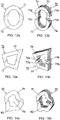
- core plates shown in the preceding Figures all had a rectangular or square shape.
- the principle of the invention is equally applicable to all other types of core plates, irrespective of their shapes, for example round, oval, quadrilateral, trapezoidal, or any closed shape whatsoever.
- all these embodiments have a constant (rectangular) cross-section.
- Fig. 12a shows an oval core plate 70 in front elevation with an oval opening, which plate 70 comprises two sub-parts 71, 72 that are joined together by oblique contact faces 71 a, 72a and 71 b, 72b (see Fig. 12b ).
- the mutually complementary contact faces of the neighboring core plates do not cross each other (at the area of the core plates).
- This configuration of contact faces may also be used for other types of core plates, rectangular, square, round, etc. The same holds for the following Figures.
- Fig. 13a is a front elevation of a quadrilateral core plate 75 with an oblique division
- Fig. 13b is a perspective view of the assembly of a transformer core with such a core plate 76. Because of the quadrilateral shape, the adjoining plates here are always of a first and a second type with mutually complementary contact faces lying in different planes.
- Fig. 14a is a front elevation of a core plate built up from two sub-parts having a random, i.e. irregular closed shape, but whose diameter is constant.
- Fig. 14b shows the assembly of a transformer core from such plates.
- the mutually complementary contact faces of neighboring plates cross each other in this case ( Fig. 14a ).
- the invention relates to a transformer core as described in claim 1, comprising a stack formed from a number of planar core plates of a magnetically permeable material, each plate consisting of a first and a second sub-part which together enclose at least one opening.
- the sub-parts can be fitted together by means of contact faces that are located on either side of the opening and that extend obliquely with respect to the centerline of the core plate.
- the invention also relates to the use of the described transformer core in a Coriolis flowmeter with the Coriolis tube extending through the opening so as to induce a current in the tube.
- the transformer core consists of a stack of core parts in alternating orientation, which core parts each comprise two contraform U-shaped plates with contact faces oriented obliquely to the cross-section of the legs of the U.
Landscapes
- Physics & Mathematics (AREA)
- Fluid Mechanics (AREA)
- General Physics & Mathematics (AREA)
- Engineering & Computer Science (AREA)
- Power Engineering (AREA)
- Measuring Volume Flow (AREA)
- Transformers For Measuring Instruments (AREA)
Applications Claiming Priority (1)
| Application Number | Priority Date | Filing Date | Title |
|---|---|---|---|
| NL1033887A NL1033887C2 (nl) | 2007-05-24 | 2007-05-24 | Transformatorkern. |
Publications (3)
| Publication Number | Publication Date |
|---|---|
| EP1995742A2 EP1995742A2 (en) | 2008-11-26 |
| EP1995742A3 EP1995742A3 (en) | 2009-02-25 |
| EP1995742B1 true EP1995742B1 (en) | 2017-08-23 |
Family
ID=38810328
Family Applications (1)
| Application Number | Title | Priority Date | Filing Date |
|---|---|---|---|
| EP08075203.3A Active EP1995742B1 (en) | 2007-05-24 | 2008-03-21 | Transformer core |
Country Status (4)
| Country | Link |
|---|---|
| US (1) | US7843306B2 (enExample) |
| EP (1) | EP1995742B1 (enExample) |
| JP (1) | JP2008294435A (enExample) |
| NL (1) | NL1033887C2 (enExample) |
Families Citing this family (10)
| Publication number | Priority date | Publication date | Assignee | Title |
|---|---|---|---|---|
| JP5192531B2 (ja) * | 2010-10-29 | 2013-05-08 | 三菱電機株式会社 | 内燃機関用点火コイル |
| DE102011107252A1 (de) * | 2011-07-14 | 2013-01-17 | Schneider Electric Sachsenwerk Gmbh | Spule zur Strombegrenzung |
| JP5937819B2 (ja) * | 2011-12-21 | 2016-06-22 | 株式会社タムラ製作所 | 電流センサ用ループコア及び電流センサ |
| US9631962B2 (en) * | 2014-03-18 | 2017-04-25 | Rosemount Inc. | Magnetic core configuration for magnetic flowmeters having a plurality of layers of magnetically permeable material |
| CN104008862A (zh) * | 2014-05-30 | 2014-08-27 | 昆山佑翔电子科技有限公司 | 变压器铁芯 |
| CN105742031B (zh) * | 2014-12-10 | 2017-11-21 | 辽宁易德实业集团有限公司 | 一种立体变压器的叠式铁芯及其工艺方法 |
| CN105469951A (zh) * | 2016-02-10 | 2016-04-06 | 齐侠 | 折叠式平面单相开口变压器铁芯 |
| JP2019009277A (ja) * | 2017-06-23 | 2019-01-17 | 株式会社タムラ製作所 | コア、コア積層体及び静止誘導器 |
| JP7402092B2 (ja) * | 2020-03-23 | 2023-12-20 | 東芝産業機器システム株式会社 | カットコア |
| JP7529005B2 (ja) * | 2021-12-22 | 2024-08-06 | Jfeスチール株式会社 | 積鉄心および積鉄心の製造方法 |
Citations (1)
| Publication number | Priority date | Publication date | Assignee | Title |
|---|---|---|---|---|
| JPS5799718A (en) * | 1980-12-12 | 1982-06-21 | Fujitsu Ltd | Assembling method for coil with magnetic core |
Family Cites Families (15)
| Publication number | Priority date | Publication date | Assignee | Title |
|---|---|---|---|---|
| DE7342490U (de) * | 1974-05-16 | Licentia Gmbh | Aus Blechen zusammengesetzter Magnetkern | |
| US2467867A (en) * | 1944-09-11 | 1949-04-19 | Gen Electric | Electromagnetic induction apparatus and method of forming same |
| GB680677A (en) | 1949-10-27 | 1952-10-08 | Comb Eng Superheater Inc | Water supply system for forced recirculation steam generator |
| GB680577A (en) * | 1950-03-30 | 1952-10-08 | N G N Electrical Ltd | Improvements in laminated magnetic cores for electric transformers |
| US2942218A (en) * | 1952-08-08 | 1960-06-21 | Mc Graw Edison Co | Core for electromagnetic induction apparatus |
| US3513423A (en) * | 1969-01-08 | 1970-05-19 | Mc Graw Edison Co | Three-phase magnetic core |
| US3918153A (en) * | 1971-03-22 | 1975-11-11 | Westinghouse Electric Corp | Method of constructing a magnetic core |
| JPS5124490Y2 (enExample) * | 1971-08-09 | 1976-06-23 | ||
| JPS5044614U (enExample) * | 1973-08-27 | 1975-05-06 | ||
| JPS549854U (enExample) * | 1977-06-24 | 1979-01-23 | ||
| US4520556A (en) * | 1981-05-04 | 1985-06-04 | General Electric Company | Methods for assembling a transformer core |
| DE4410160C1 (de) * | 1994-03-24 | 1995-10-05 | Ulrich Dipl Ing Elsen | Hochwärmebeständige Spule, insbesondere zur Verwendung als Antriebsspule und als Meßspule zum Antrieb und zum Messen der Schwingungen des Schwingrohres einer Vorrichtung zum Messen der Masse eines durch eine Rohrleitung fließenden Mediums |
| US5777537A (en) * | 1996-05-08 | 1998-07-07 | Espey Mfg. & Electronics Corp. | Quiet magnetic structures such as power transformers and reactors |
| US7057489B2 (en) * | 1997-08-21 | 2006-06-06 | Metglas, Inc. | Segmented transformer core |
| JP4387769B2 (ja) * | 2003-11-18 | 2009-12-24 | 株式会社東芝 | 巻鉄心及び変圧器 |
-
2007
- 2007-05-24 NL NL1033887A patent/NL1033887C2/nl not_active IP Right Cessation
-
2008
- 2008-03-21 EP EP08075203.3A patent/EP1995742B1/en active Active
- 2008-04-30 JP JP2008118139A patent/JP2008294435A/ja active Pending
- 2008-05-08 US US12/117,050 patent/US7843306B2/en active Active
Patent Citations (1)
| Publication number | Priority date | Publication date | Assignee | Title |
|---|---|---|---|---|
| JPS5799718A (en) * | 1980-12-12 | 1982-06-21 | Fujitsu Ltd | Assembling method for coil with magnetic core |
Also Published As
| Publication number | Publication date |
|---|---|
| NL1033887C2 (nl) | 2008-11-25 |
| US7843306B2 (en) | 2010-11-30 |
| EP1995742A3 (en) | 2009-02-25 |
| JP2008294435A (ja) | 2008-12-04 |
| US20080290982A1 (en) | 2008-11-27 |
| EP1995742A2 (en) | 2008-11-26 |
Similar Documents
| Publication | Publication Date | Title |
|---|---|---|
| EP1995742B1 (en) | Transformer core | |
| US4736635A (en) | Electromagnetic flowmeter | |
| EP0418033A1 (en) | Electromagnetic flowmeter | |
| EP1719982A1 (en) | Mass flowmeter of the Coriolis type | |
| JP7087083B2 (ja) | 変圧器鉄心および変圧器 | |
| US6858954B2 (en) | Reciprocating motor | |
| JP2014220435A (ja) | リアクタ | |
| CN103811156B (zh) | 变压器和用于设置绕组的方法 | |
| JP4174725B2 (ja) | 電磁流量計 | |
| JP4359664B2 (ja) | 電磁流量計 | |
| JPH01276710A (ja) | スイッチングモード・パワー・トランス | |
| JPS5944812A (ja) | 漏洩変圧器用コア組立体 | |
| CN111076781A (zh) | 磁感应式流量测量仪、磁环路装置和用于其制造的方法 | |
| RU2007139257A (ru) | Индукционный нагреватель текучих сред | |
| JP3774647B2 (ja) | 電磁石および荷電粒子照射装置 | |
| JP3490300B2 (ja) | 電磁流量計及びその製造方法 | |
| JP2001241981A (ja) | 電磁流量計 | |
| JPH04236162A (ja) | 誘導型電磁ポンプ | |
| JP2005207971A (ja) | 電磁流量計 | |
| KR101904100B1 (ko) | 변압기의 철심 | |
| JP2005061847A (ja) | 電磁流量計 | |
| JPS59198319A (ja) | 電磁流量計 | |
| JPH04132914A (ja) | 電磁流量計 | |
| JPS6365182A (ja) | 可動磁石式ダイヤフラムポンプ | |
| CN110885116A (zh) | 一种水磁化装置 |
Legal Events
| Date | Code | Title | Description |
|---|---|---|---|
| PUAI | Public reference made under article 153(3) epc to a published international application that has entered the european phase |
Free format text: ORIGINAL CODE: 0009012 |
|
| AK | Designated contracting states |
Kind code of ref document: A2 Designated state(s): AT BE BG CH CY CZ DE DK EE ES FI FR GB GR HR HU IE IS IT LI LT LU LV MC MT NL NO PL PT RO SE SI SK TR |
|
| AX | Request for extension of the european patent |
Extension state: AL BA MK RS |
|
| PUAL | Search report despatched |
Free format text: ORIGINAL CODE: 0009013 |
|
| AK | Designated contracting states |
Kind code of ref document: A3 Designated state(s): AT BE BG CH CY CZ DE DK EE ES FI FR GB GR HR HU IE IS IT LI LT LU LV MC MT NL NO PL PT RO SE SI SK TR |
|
| AX | Request for extension of the european patent |
Extension state: AL BA MK RS |
|
| 17P | Request for examination filed |
Effective date: 20090115 |
|
| 17Q | First examination report despatched |
Effective date: 20090529 |
|
| AKX | Designation fees paid |
Designated state(s): AT BE BG CH CY CZ DE DK EE ES FI FR GB GR HR HU IE IS IT LI LT LU LV MC MT NL NO PL PT RO SE SI SK TR |
|
| GRAP | Despatch of communication of intention to grant a patent |
Free format text: ORIGINAL CODE: EPIDOSNIGR1 |
|
| INTG | Intention to grant announced |
Effective date: 20170322 |
|
| RIN1 | Information on inventor provided before grant (corrected) |
Inventor name: MEHENDALE, ADITYA C/O BERKIN B.V. Inventor name: LOETTERS, JOOST Inventor name: HAGEDOORN, WOUTER |
|
| GRAS | Grant fee paid |
Free format text: ORIGINAL CODE: EPIDOSNIGR3 |
|
| GRAA | (expected) grant |
Free format text: ORIGINAL CODE: 0009210 |
|
| AK | Designated contracting states |
Kind code of ref document: B1 Designated state(s): AT BE BG CH CY CZ DE DK EE ES FI FR GB GR HR HU IE IS IT LI LT LU LV MC MT NL NO PL PT RO SE SI SK TR |
|
| REG | Reference to a national code |
Ref country code: GB Ref legal event code: FG4D |
|
| REG | Reference to a national code |
Ref country code: CH Ref legal event code: EP |
|
| REG | Reference to a national code |
Ref country code: AT Ref legal event code: REF Ref document number: 922163 Country of ref document: AT Kind code of ref document: T Effective date: 20170915 |
|
| REG | Reference to a national code |
Ref country code: IE Ref legal event code: FG4D |
|
| REG | Reference to a national code |
Ref country code: DE Ref legal event code: R096 Ref document number: 602008051719 Country of ref document: DE |
|
| REG | Reference to a national code |
Ref country code: NL Ref legal event code: FP |
|
| REG | Reference to a national code |
Ref country code: CH Ref legal event code: NV Representative=s name: DR. LUSUARDI AG, CH |
|
| REG | Reference to a national code |
Ref country code: LT Ref legal event code: MG4D |
|
| REG | Reference to a national code |
Ref country code: AT Ref legal event code: MK05 Ref document number: 922163 Country of ref document: AT Kind code of ref document: T Effective date: 20170823 |
|
| PG25 | Lapsed in a contracting state [announced via postgrant information from national office to epo] |
Ref country code: FI Free format text: LAPSE BECAUSE OF FAILURE TO SUBMIT A TRANSLATION OF THE DESCRIPTION OR TO PAY THE FEE WITHIN THE PRESCRIBED TIME-LIMIT Effective date: 20170823 Ref country code: LT Free format text: LAPSE BECAUSE OF FAILURE TO SUBMIT A TRANSLATION OF THE DESCRIPTION OR TO PAY THE FEE WITHIN THE PRESCRIBED TIME-LIMIT Effective date: 20170823 Ref country code: HR Free format text: LAPSE BECAUSE OF FAILURE TO SUBMIT A TRANSLATION OF THE DESCRIPTION OR TO PAY THE FEE WITHIN THE PRESCRIBED TIME-LIMIT Effective date: 20170823 Ref country code: AT Free format text: LAPSE BECAUSE OF FAILURE TO SUBMIT A TRANSLATION OF THE DESCRIPTION OR TO PAY THE FEE WITHIN THE PRESCRIBED TIME-LIMIT Effective date: 20170823 Ref country code: SE Free format text: LAPSE BECAUSE OF FAILURE TO SUBMIT A TRANSLATION OF THE DESCRIPTION OR TO PAY THE FEE WITHIN THE PRESCRIBED TIME-LIMIT Effective date: 20170823 Ref country code: NO Free format text: LAPSE BECAUSE OF FAILURE TO SUBMIT A TRANSLATION OF THE DESCRIPTION OR TO PAY THE FEE WITHIN THE PRESCRIBED TIME-LIMIT Effective date: 20171123 |
|
| PG25 | Lapsed in a contracting state [announced via postgrant information from national office to epo] |
Ref country code: GR Free format text: LAPSE BECAUSE OF FAILURE TO SUBMIT A TRANSLATION OF THE DESCRIPTION OR TO PAY THE FEE WITHIN THE PRESCRIBED TIME-LIMIT Effective date: 20171124 Ref country code: BG Free format text: LAPSE BECAUSE OF FAILURE TO SUBMIT A TRANSLATION OF THE DESCRIPTION OR TO PAY THE FEE WITHIN THE PRESCRIBED TIME-LIMIT Effective date: 20171123 Ref country code: ES Free format text: LAPSE BECAUSE OF FAILURE TO SUBMIT A TRANSLATION OF THE DESCRIPTION OR TO PAY THE FEE WITHIN THE PRESCRIBED TIME-LIMIT Effective date: 20170823 Ref country code: IS Free format text: LAPSE BECAUSE OF FAILURE TO SUBMIT A TRANSLATION OF THE DESCRIPTION OR TO PAY THE FEE WITHIN THE PRESCRIBED TIME-LIMIT Effective date: 20171223 Ref country code: PL Free format text: LAPSE BECAUSE OF FAILURE TO SUBMIT A TRANSLATION OF THE DESCRIPTION OR TO PAY THE FEE WITHIN THE PRESCRIBED TIME-LIMIT Effective date: 20170823 Ref country code: LV Free format text: LAPSE BECAUSE OF FAILURE TO SUBMIT A TRANSLATION OF THE DESCRIPTION OR TO PAY THE FEE WITHIN THE PRESCRIBED TIME-LIMIT Effective date: 20170823 |
|
| REG | Reference to a national code |
Ref country code: FR Ref legal event code: PLFP Year of fee payment: 11 |
|
| PG25 | Lapsed in a contracting state [announced via postgrant information from national office to epo] |
Ref country code: CZ Free format text: LAPSE BECAUSE OF FAILURE TO SUBMIT A TRANSLATION OF THE DESCRIPTION OR TO PAY THE FEE WITHIN THE PRESCRIBED TIME-LIMIT Effective date: 20170823 Ref country code: RO Free format text: LAPSE BECAUSE OF FAILURE TO SUBMIT A TRANSLATION OF THE DESCRIPTION OR TO PAY THE FEE WITHIN THE PRESCRIBED TIME-LIMIT Effective date: 20170823 Ref country code: DK Free format text: LAPSE BECAUSE OF FAILURE TO SUBMIT A TRANSLATION OF THE DESCRIPTION OR TO PAY THE FEE WITHIN THE PRESCRIBED TIME-LIMIT Effective date: 20170823 |
|
| REG | Reference to a national code |
Ref country code: DE Ref legal event code: R097 Ref document number: 602008051719 Country of ref document: DE |
|
| PG25 | Lapsed in a contracting state [announced via postgrant information from national office to epo] |
Ref country code: EE Free format text: LAPSE BECAUSE OF FAILURE TO SUBMIT A TRANSLATION OF THE DESCRIPTION OR TO PAY THE FEE WITHIN THE PRESCRIBED TIME-LIMIT Effective date: 20170823 Ref country code: IT Free format text: LAPSE BECAUSE OF FAILURE TO SUBMIT A TRANSLATION OF THE DESCRIPTION OR TO PAY THE FEE WITHIN THE PRESCRIBED TIME-LIMIT Effective date: 20170823 Ref country code: SK Free format text: LAPSE BECAUSE OF FAILURE TO SUBMIT A TRANSLATION OF THE DESCRIPTION OR TO PAY THE FEE WITHIN THE PRESCRIBED TIME-LIMIT Effective date: 20170823 |
|
| PLBE | No opposition filed within time limit |
Free format text: ORIGINAL CODE: 0009261 |
|
| STAA | Information on the status of an ep patent application or granted ep patent |
Free format text: STATUS: NO OPPOSITION FILED WITHIN TIME LIMIT |
|
| 26N | No opposition filed |
Effective date: 20180524 |
|
| PG25 | Lapsed in a contracting state [announced via postgrant information from national office to epo] |
Ref country code: SI Free format text: LAPSE BECAUSE OF FAILURE TO SUBMIT A TRANSLATION OF THE DESCRIPTION OR TO PAY THE FEE WITHIN THE PRESCRIBED TIME-LIMIT Effective date: 20170823 |
|
| PG25 | Lapsed in a contracting state [announced via postgrant information from national office to epo] |
Ref country code: MC Free format text: LAPSE BECAUSE OF FAILURE TO SUBMIT A TRANSLATION OF THE DESCRIPTION OR TO PAY THE FEE WITHIN THE PRESCRIBED TIME-LIMIT Effective date: 20170823 |
|
| REG | Reference to a national code |
Ref country code: BE Ref legal event code: MM Effective date: 20180331 |
|
| REG | Reference to a national code |
Ref country code: IE Ref legal event code: MM4A |
|
| PG25 | Lapsed in a contracting state [announced via postgrant information from national office to epo] |
Ref country code: LU Free format text: LAPSE BECAUSE OF NON-PAYMENT OF DUE FEES Effective date: 20180321 |
|
| PG25 | Lapsed in a contracting state [announced via postgrant information from national office to epo] |
Ref country code: IE Free format text: LAPSE BECAUSE OF NON-PAYMENT OF DUE FEES Effective date: 20180321 |
|
| PG25 | Lapsed in a contracting state [announced via postgrant information from national office to epo] |
Ref country code: BE Free format text: LAPSE BECAUSE OF NON-PAYMENT OF DUE FEES Effective date: 20180331 |
|
| PG25 | Lapsed in a contracting state [announced via postgrant information from national office to epo] |
Ref country code: MT Free format text: LAPSE BECAUSE OF NON-PAYMENT OF DUE FEES Effective date: 20180321 |
|
| PG25 | Lapsed in a contracting state [announced via postgrant information from national office to epo] |
Ref country code: TR Free format text: LAPSE BECAUSE OF FAILURE TO SUBMIT A TRANSLATION OF THE DESCRIPTION OR TO PAY THE FEE WITHIN THE PRESCRIBED TIME-LIMIT Effective date: 20170823 |
|
| PG25 | Lapsed in a contracting state [announced via postgrant information from national office to epo] |
Ref country code: HU Free format text: LAPSE BECAUSE OF FAILURE TO SUBMIT A TRANSLATION OF THE DESCRIPTION OR TO PAY THE FEE WITHIN THE PRESCRIBED TIME-LIMIT; INVALID AB INITIO Effective date: 20080321 Ref country code: PT Free format text: LAPSE BECAUSE OF FAILURE TO SUBMIT A TRANSLATION OF THE DESCRIPTION OR TO PAY THE FEE WITHIN THE PRESCRIBED TIME-LIMIT Effective date: 20170823 |
|
| PG25 | Lapsed in a contracting state [announced via postgrant information from national office to epo] |
Ref country code: CY Free format text: LAPSE BECAUSE OF FAILURE TO SUBMIT A TRANSLATION OF THE DESCRIPTION OR TO PAY THE FEE WITHIN THE PRESCRIBED TIME-LIMIT Effective date: 20170823 |
|
| P01 | Opt-out of the competence of the unified patent court (upc) registered |
Effective date: 20230525 |
|
| PGFP | Annual fee paid to national office [announced via postgrant information from national office to epo] |
Ref country code: CH Payment date: 20250401 Year of fee payment: 18 |
|
| REG | Reference to a national code |
Ref country code: CH Ref legal event code: U11 Free format text: ST27 STATUS EVENT CODE: U-0-0-U10-U11 (AS PROVIDED BY THE NATIONAL OFFICE) Effective date: 20260401 |
|
| PGFP | Annual fee paid to national office [announced via postgrant information from national office to epo] |
Ref country code: GB Payment date: 20260324 Year of fee payment: 19 |
|
| PGFP | Annual fee paid to national office [announced via postgrant information from national office to epo] |
Ref country code: DE Payment date: 20260319 Year of fee payment: 19 |
|
| PGFP | Annual fee paid to national office [announced via postgrant information from national office to epo] |
Ref country code: NL Payment date: 20260319 Year of fee payment: 19 |
|
| PGFP | Annual fee paid to national office [announced via postgrant information from national office to epo] |
Ref country code: FR Payment date: 20260320 Year of fee payment: 19 |