EP1995652B1 - Systeme und Verfahren zur Änderung von Turbinensteuersystemen - Google Patents
Systeme und Verfahren zur Änderung von Turbinensteuersystemen Download PDFInfo
- Publication number
- EP1995652B1 EP1995652B1 EP08156038A EP08156038A EP1995652B1 EP 1995652 B1 EP1995652 B1 EP 1995652B1 EP 08156038 A EP08156038 A EP 08156038A EP 08156038 A EP08156038 A EP 08156038A EP 1995652 B1 EP1995652 B1 EP 1995652B1
- Authority
- EP
- European Patent Office
- Prior art keywords
- processor
- communication protocol
- communication
- communications
- protocol
- Prior art date
- Legal status (The legal status is an assumption and is not a legal conclusion. Google has not performed a legal analysis and makes no representation as to the accuracy of the status listed.)
- Not-in-force
Links
- 238000000034 method Methods 0.000 title claims description 34
- 238000004891 communication Methods 0.000 claims description 202
- 230000002093 peripheral effect Effects 0.000 claims description 18
- 238000012806 monitoring device Methods 0.000 claims description 13
- 230000000717 retained effect Effects 0.000 claims description 2
- 238000010586 diagram Methods 0.000 description 7
- 230000006870 function Effects 0.000 description 7
- 238000012545 processing Methods 0.000 description 6
- 238000004590 computer program Methods 0.000 description 5
- 238000013519 translation Methods 0.000 description 5
- 230000014616 translation Effects 0.000 description 5
- 230000005284 excitation Effects 0.000 description 4
- 239000000446 fuel Substances 0.000 description 3
- 230000008569 process Effects 0.000 description 3
- 230000008901 benefit Effects 0.000 description 2
- 230000005540 biological transmission Effects 0.000 description 2
- 238000013461 design Methods 0.000 description 2
- 238000004519 manufacturing process Methods 0.000 description 2
- 238000005259 measurement Methods 0.000 description 2
- 238000012986 modification Methods 0.000 description 2
- 230000004048 modification Effects 0.000 description 2
- 230000004044 response Effects 0.000 description 2
- 239000004065 semiconductor Substances 0.000 description 2
- 230000006399 behavior Effects 0.000 description 1
- 238000006243 chemical reaction Methods 0.000 description 1
- 238000005516 engineering process Methods 0.000 description 1
- 238000012544 monitoring process Methods 0.000 description 1
- 238000010248 power generation Methods 0.000 description 1
- 238000009420 retrofitting Methods 0.000 description 1
Images

Classifications
-
- F—MECHANICAL ENGINEERING; LIGHTING; HEATING; WEAPONS; BLASTING
- F01—MACHINES OR ENGINES IN GENERAL; ENGINE PLANTS IN GENERAL; STEAM ENGINES
- F01D—NON-POSITIVE DISPLACEMENT MACHINES OR ENGINES, e.g. STEAM TURBINES
- F01D19/00—Starting of machines or engines; Regulating, controlling, or safety means in connection therewith
-
- G—PHYSICS
- G05—CONTROLLING; REGULATING
- G05B—CONTROL OR REGULATING SYSTEMS IN GENERAL; FUNCTIONAL ELEMENTS OF SUCH SYSTEMS; MONITORING OR TESTING ARRANGEMENTS FOR SUCH SYSTEMS OR ELEMENTS
- G05B19/00—Programme-control systems
- G05B19/02—Programme-control systems electric
- G05B19/04—Programme control other than numerical control, i.e. in sequence controllers or logic controllers
- G05B19/042—Programme control other than numerical control, i.e. in sequence controllers or logic controllers using digital processors
-
- F—MECHANICAL ENGINEERING; LIGHTING; HEATING; WEAPONS; BLASTING
- F01—MACHINES OR ENGINES IN GENERAL; ENGINE PLANTS IN GENERAL; STEAM ENGINES
- F01D—NON-POSITIVE DISPLACEMENT MACHINES OR ENGINES, e.g. STEAM TURBINES
- F01D21/00—Shutting-down of machines or engines, e.g. in emergency; Regulating, controlling, or safety means not otherwise provided for
-
- F—MECHANICAL ENGINEERING; LIGHTING; HEATING; WEAPONS; BLASTING
- F02—COMBUSTION ENGINES; HOT-GAS OR COMBUSTION-PRODUCT ENGINE PLANTS
- F02C—GAS-TURBINE PLANTS; AIR INTAKES FOR JET-PROPULSION PLANTS; CONTROLLING FUEL SUPPLY IN AIR-BREATHING JET-PROPULSION PLANTS
- F02C9/00—Controlling gas-turbine plants; Controlling fuel supply in air- breathing jet-propulsion plants
-
- G—PHYSICS
- G05—CONTROLLING; REGULATING
- G05B—CONTROL OR REGULATING SYSTEMS IN GENERAL; FUNCTIONAL ELEMENTS OF SUCH SYSTEMS; MONITORING OR TESTING ARRANGEMENTS FOR SUCH SYSTEMS OR ELEMENTS
- G05B2219/00—Program-control systems
- G05B2219/20—Pc systems
- G05B2219/25—Pc structure of the system
- G05B2219/25204—Translate between different communication protocols
Definitions
- the invention relates generally to turbine control systems, and more particularly relates to methods and systems for modifying hardware of turbine control systems.
- Industrial and power generation turbines have control systems that monitor and control their operation. These control systems typically include one or more processor cards configured as main controller processors running application code that implements the control system functions. Additionally, there typically exist processor cards configured as input-output (“IO") processor cards that receive and send signals to and from monitoring devices on the turbines and other peripheral auxiliary equipment. The IO processor cards may interface with terminal boards in communication with the monitoring devices on the turbine or auxiliary equipment.
- the main controller processors may communicate with each other, with the 10 processors, and with a general communications network using a standard communication protocol. Communication protocols may vary depending upon factors such as the control system application, the site architecture, and the age of the control system.
- RS485 also known as EIA-485
- RS232 Modbus
- ARCNET ARCNET
- Ethernet and USB are examples of common communication protocols used in control systems.
- Older control systems may become outdated and need to be replaced or updated to allow implementing current control system capabilities, such as processing-intensive model-based controls, PID controls, and more powerful application tools, as well as enable communications via open communications protocol interfaces with third party systems.
- current control system capabilities such as processing-intensive model-based controls, PID controls, and more powerful application tools, as well as enable communications via open communications protocol interfaces with third party systems.
- simple and quick upgrades are more cost-effective by requiring less labor, less downtime, and by providing quicker realization of the benefits generated by the upgraded control systems.
- Turbine control systems typically have a large number of input and output termination points, for example terminal boards and terminal screws, where peripheral sensor and control devices communicate between the control system and the turbines.
- a control system upgrade that requires reconnecting each existing input and output termination point is extremely labor-intensive and increases the amount of time during which the turbines are off-line.
- some system upgrades may include replacing hardware, such as new microprocessors that communicate using different (and typically more modem) protocols from the existing IO processor cards communicating with the terminal boards.
- the Mark V turbine control system manufactured by General Electric has achieved a large installed base during the many years of production. While the GE Mark V turbine control system remains a viable platform for existing owners who use it today, its ability to accept some control upgrades is limited. As advanced control methods for turbines are developed, an upgrade path is needed for the existing GE Mark V turbine control systems to upgrade to either the GE Mark Ve or GE Mark VIe control systems as discussed in XP002493606.
- One aspect of the upgrade path includes upgrading at least some of the existing legacy processors to newer, current microprocessors capable of handling more complex operations as required by the upgraded control system logic.
- some preferred microprocessors that may replace the legacy processors are the current 32-bit MPC8xx family-based microprocessors, such as the PowerQUICC processor developed by Freescale Semiconductor, communicating via the Ethernet communication protocol, while some of the legacy processors are 16-bit 80186- or 80196-type processors, as developed by Intel Corporation, that retain the serial RS485 communication protocol.
- Embodiments of the invention can address some or all of the needs described above.
- Embodiments of the invention are directed generally to systems and methods for modifying a turbine control system.
- a method for modifying a turbine control system may be provided for. The method may include replacing at least one legacy main controller processor communicating in a first communication protocol with a current main control processor communicating in a second communication protocol. The method may further include retaining at least one legacy IO processor in communication with at least one turbine monitoring device communicating in the first communication protocol. Additionally, the method may include providing at least one converter in communication with the current main controller processor or processors and in communication with the legacy IO processor or processors.
- the converter may translate communications from the current main controller processor or processors from the second communication protocol to the first communication protocol, and may further transmit the communications to the legacy IO processor or processors.
- the converter may also translate communications from the legacy IO processor or processors from the first communication protocol to the second communication protocol, and may further transmit the communications to the current main controller processor or processors.
- control system for controlling at least one turbine may be provided for.
- the system may include at least one IO processor in communication with at least one turbine monitoring device.
- the IO processor or processors and the turbine monitoring device or devices may be configured to communicate in a first communication protocol.
- the system may further include at least one converter in communication with the IO processor or processors.
- the system may include at least one main controller processor in communication with the converter or converters, which may be configured to communicate in a second communication protocol.
- the converter or converters may be configured to translate communications from the IO processor or processors to the main controller processor or processors by translating the first communication protocol to the second communication protocol.
- the converter or converters may be configured to translate communications from the main controller processor or processors to the IO processor or processors by translating the second communication protocol to the first communication protocol.
- a method for modifying a control system including a first processor and a second processor may be provided for.
- the first and second processors may communicate in a first communication protocol.
- the method may include replacing the second processor with a third processor communicating in a second communication protocol.
- the method may further include retaining the first processor.
- the first processor may be in communication with at least one monitoring device and communicates in the first communication protocol.
- the method may include providing a converter in communication with the first and the third processors.
- the method may include translating communications from the first processor from the first communication protocol to the second communication protocol, and translating communications from the third processor from the second communication protocol to the first communication protocol. The translations may be done by the converter.
- the application references block diagrams of systems, methods, apparatuses, and computer program products according to at least one embodiment described herein. It will be understood that at least some of the blocks of the block diagrams, and combinations of blocks in the block diagrams, respectively, may be implemented at least partially by computer program instructions. These computer program instructions may be loaded onto a general purpose computer, special purpose computer, special purpose hardware-based computer, or other programmable data processing apparatus to produce a machine, such that the instructions which execute on the computer or other programmable data processing apparatus create means for implementing the functionality of at least some of the blocks of the block diagrams, or combinations of blocks in the block diagrams discussed in detail in the descriptions below.
- These computer program instructions may also be stored in a computer-readable memory that can direct a computer or other programmable data processing apparatus to function in a particular manner, such that the instructions stored in the computer-readable memory produce an article of manufacture including instruction means that implement the function specified in the block or blocks.
- the computer program instructions may also be loaded onto a computer or other programmable data processing apparatus to cause a series of operational steps to be performed on the computer or other programmable apparatus to produce a computer implemented process such that the instructions that execute on the computer or other programmable apparatus provide steps for implementing the functions specified in the block or blocks.
- One or more components of the systems and one or more steps of the methods described herein may be implemented through an application program running on an operating system of a computer. They also may be practiced with other computer system configurations, including hand-held devices, multiprocessor systems, microprocessor based, or programmable consumer electronics, mini-computers, mainframe computers, etc.
- Application programs that are components of the systems and methods described herein may include routines, programs, components, data structures, etc. that implement certain abstract data types and perform certain tasks or actions.
- the application program in whole or in part
- the application program may be located in local memory, or in other storage.
- the application program in whole or in part
- upgrading a turbine control system allows implementing current systems advances, such as, performance increasing tools, improved monitoring, more robust reporting, and more responsive and accurate control functions.
- Embodiments of the systems and methods disclosed in this application allow upgrading some components of the control system, for example main controller processor cards, while retaining other existing components to expedite the upgrade process and limit disruption of the turbine operation.
- These embodiments of the systems and methods allow upgraded components to communicate with existing, legacy components through the use of one or more converters that perform translations on disparate communication protocols.
- a legacy control system may include one or more main controller processors and one or more input-output ("IO") processors that communicate using the same communication protocol, such as the RS485 protocol.
- IO input-output
- control system upgrades may be performed in a more productive manner by using these systems and methods because fewer components need to be replaced or reconfigured. More specifically, by retaining the legacy IO processors, the terminations into and out of the control system do not have to be reconfigured, while one or more protocol converters allow for communication between the legacy IO processors and the upgraded main controller processors.
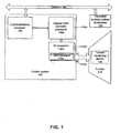
- Fig. 1 depicts a control system 100 in communication with a turbine 110.
- the turbine 110 may be a steam turbine or a gas turbine.
- An example turbine 110 referred to herein may be a gas turbine.
- the control system 100 may be a computer based control system running one or more microprocessors as is known in the art.
- the control system 100 executes control logic consisting of programs and operations to control the operation of the turbine 110 using sensor inputs, instructions from human operators, and computer implemented schedules and/or models.
- the control command signals generated by the controller 100 may cause actuators on the turbine to, for example, adjust valves between the fuel supply and combustors that regulate the flow, fuel splits, and type of fuel flowing to the combustors; adjust inlet guide vanes on the compressor; adjust inlet bleed heat; as well as activate other control settings on the turbine 110.
- the control system 100 may be, for example, the GE Mark V turbine control system.
- the control system 100 includes one or more IO processors 120a, which may be a card that includes one or more microprocessors configured to communicate with a terminal board or boards 170a.
- the IO processor 120a may be a discrete processor configured to receive binary data indicating one of two states, typically off/on or yes/no.
- the IO processor 120a may be an analog acquisition processor configured to receive analog variable signals.
- the terminal board 170a includes the physical input and output termination points for devices in electrical communication with the control system.
- the IO processor 120a may communicate, via its connection to the terminal board 170a, with one or more turbine monitoring devices 130, such as, for example, compressor inlet pressure sensors, compressor inlet temperature sensors, compressor discharge pressure sensors, compressor discharge temperature sensors, turbine exhaust temperature sensors, generator power output sensors, strain gauges, or the like, is are known in the art. It is appreciated that more than one IO processors 120a-120n may be included in an embodiment of the control system 100, and that they may be configured in parallel, and that more than one IO processor 120a-120n may receive the same signal so as to maintain redundancy in the system. Further, it is also appreciated that the control system 100 may include both discrete and analog IO processors 120a-120n, each receiving different signal types. Similarly, for each IO processor 120a-120n, there may be one or more terminal boards 170a-170n.
- turbine monitoring devices 130 such as, for example, compressor inlet pressure sensors, compressor inlet temperature sensors, compressor discharge pressure sensors, compressor discharge temperature sensors, turbine exhaust temperature sensors, generator power output sensors
- the control system 100 further includes at least one legacy main controller processor 140a configured to execute the control system logic.
- the legacy main controller processor 140a may be a card that includes a microprocessor or microcontroller, as is known in the art.
- the legacy main controller processor 140a may include more than one microprocessor, each performing separate functions of the legacy main controller processor 140a, for example, communicating with other hardware components in the control system 100 and performing the control logic operations.
- multiple microprocessors in the legacy main controller processor 140a may perform the same functions as a redundant design.
- the legacy main controller processor 140a will be referred to herein as a single component, despite the many alternative configurations as are known in the art.
- the legacy main controller processor 140a is configured to ultimately communicate with the IO processors 120a, to receive operating measurements as sensed by the one or more turbine monitoring devices 130, as described above, and to send control command signals to the IO processors 120a to cause a response in the operation of the turbine 110.
- the communications processor 180 may be another processor or processors, the communications processor 180, for communicating, via a legacy network 190, with other peripheral auxiliary turbine components 150, such as sensors, monitors, or control devices, for example, other control panels, for example, an excitation panel controlling the generator excitation field, or a human machine interface.
- the communications processor 180 also may be in communication with the legacy main controller processor 140a and a second IO processor 120a.
- the communications processor may be the means by which the control system communicates with the legacy network 190, such as a plant network providing connectivity with other devices, control systems, human machine interfaces, or the like.
- the communications processor 180 and the legacy network 190 communicate using the same communications protocol, for example the ARCNET protocol.
- the legacy main controller processor 140a may communicate with other peripheral auxiliary turbine components 150 via the legacy network 190.
- control system 100 may include multiple legacy main controller processors 140a-140n in parallel communication with each other so as to provide redundant communications and eliminate a single point of failure at the point of the legacy main controller processor 140a-140n.
- redundant main controller processors 140a-140n is the legacy main controller processor 140a-140n configured in a triple redundant configuration having three similarly configured legacy main controller processors 140a-140n in parallel communication.
- control system 100 may include a single legacy main controller processor 140a configured in a simplex, non-redundant configuration.
- processors are referred to as standalone components any processor discussed herein may be one component of a core, which is made up of processor cards and boards.
- one core may include a legacy main controller processor 140a (on a processor card), an IO processor 120a (on a processor card), and a termination board 170a (on a board), each in electrical communication with each other as described herein. It is appreciated that the examples provided herein are not intended to be limiting.
- the legacy main controller processor 140a is to be upgraded from an older, less sophisticated processor to a more current microprocessor, or a card including one or more microprocessors or microcontrollers, as is known in the art.
- an upgraded main controller will be referred to as the current main controller processor 200a herein.
- the main controller upgrade, or retrofit may be performed for multiple reasons, including allowing more advanced control logic to be run by the control system, such as advanced modeling or predictive controlling of the turbine behavior, and to improve device communication and connectivity technology.
- a GE Mark V turbine control system may include the legacy main controller processor 140a running on 16-bit 80186/80196-type processors, as developed by Intel Corporation.
- New advances in turbine control systems may be included in legacy control systems after upgrading the legacy main controller processor 140a to the current main controller processor 200a, using current components, such as a 32-bit MPC8xx family-based microprocessors, like the PowerQUICC processors developed by Freescale Semiconductor.
- the legacy main controller processors 140a communicate using the RS485 communication protocol, while the current main controller processor 200a is capable of communicating in the Ethernet communication protocol, or a variation thereof, as is known in the art.
- upgrading to the current main controller processor 200a allows connectivity to an upgraded current network 230 based on the Ethernet protocol, rather than limiting connectivity via the communications processor 180 (or the current communications processor 210 as described further below) to a network 190 based on the ARCNET protocol as discussed in reference to FIG. 1 .
- the IO processors 120a remain the legacy IO processors 120a and are not upgraded.
- One reason to retain the legacy IO processors 120a is to eliminate the need to replace and/or reconfigure the legacy input and output terminations at the terminal boards 170a. Retaining the legacy terminations increases the reliability and quality of the upgrade by reducing any errors that may result from reconfiguring and re-terminating each input and output connector. Furthermore, upgrade completion times may be drastically reduced by eliminating the need to reconfigure the legacy terminations.
- the legacy IO processors 120a communicated with the legacy main controller processors 140a using the RS485 communication protocol before the upgrade, and cannot directly communicate with components communicating in a different communication protocol, such as the Ethernet protocol, like the upgraded current main controller processor 200a.
- one or more converters 220a are included in the turbine control system 100.
- the converter 220a is in communication with the legacy IO processor 120a and the current main controller processor 200a, performing translation from one communication protocol to another while transmitting communication signals between the two.
- the converter 220a receives RS485 communication signals from the legacy 10 processor 120a and translates them to the Ethernet protocol prior to completing the transmission of the communication signals to the current main controller processor 200a.
- the converter 220a receives Ethernet communication signals from the current main controller processor 200a and translates them to the RS485 protocol prior to completing the transmission of the communication signals to the legacy IO processor 120a.
- peripheral auxiliary turbine components 150 may send and receive signals to and from the peripheral auxiliary turbine components 150, for example, an excitation panel controlling a generator excitation field, and the current main controller processor 200a, translating the communication signals between the Ethernet and ARCNET communication protocols.
- ARCNET yet another communication protocol
- the communications processor 180 may be upgraded like the current main controller processor 200a, in reference to FIGS. 2 and 3 , to a current communications processor 210.
- the current communications processor 210 may be configured to communicate with other peripheral auxiliary turbine components 150, via the legacy network 190, that communicate in a third communication protocol, such as the ARCNET protocol.
- a second converter 220a is included to translate communications between the current communications processor 210 and the other peripheral c auxiliary turbine components 150 - between the ARCNET protocol and the Ethernet protocol.
- upgrading to the current communications processor 210 and including the converter 220a allows a turbine control system upgrade that is non-invasive to other devices on the legacy network 190, whereas the current main controller processor 200a allows connectivity to the current network 230 design based on the Ethernet protocol rather than limiting connectivity to only the legacy network 190 based on the ARCNET protocol.
- other components communicating in different communication protocols may be in communication with yet other converters 220a, so as to translate between each of the communication protocols, allowing for partial upgrades, or retrofitting, of some new, current components while retaining other existing, legacy components.
- Other examples of communication protocols that may be translated by one or more converters are RS232, Modbus, and USB.
- multiple converters 220a-220n may be provided.
- multiple converters 220a-220n may be configured in a redundant, parallel configuration.
- the converter 220a may be configured as a processor board having two cards, a data acquisition card and a processor card.
- the data acquisition card may, for example, utilize FPGA components, as is known in the art, and communicate signals received to the processor card for converting the communications protocol.
- the converter 220a configured to communicate between the main controller processor 200a and legacy IO processor 120a communicating in RS485 protocol may include, for example, an RS485 TSP serial bus connector, as is known in the art, for sending and receiving signals in the RS485 communications protocol, and one or more Ethernet RJ-45 connectors, as are known in the art, for sending and receiving signals in the Ethernet communications protocol.
- the converter 220a configured to communicate between the main controller processor 200a and the legacy network 190 communicating in ARCNET protocol may include, for example, BNC coaxial connector, as is known in the art, for sending and receiving signals in the ARCNET communication protocol, and one or more Ethernet RJ-45 connectors for sending and receiving signals in the Ethernet communication protocol. Further, the converter 220a may be included as a component on the main controller processor core and communication processor core.
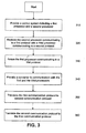
- FIG. 3 shows an illustrative embodiment of a method to upgrade the control system 100 as described in reference to FIG. 1 .
- a control system 100 having at least two processors is provided for.
- the first processor may be, for example, the legacy IO processor 120a.
- the second processor may be, for example, the legacy main controller processor 140a in communication with the legacy IO processor 120a.
- the first processor and the second processor communicate using the same communication protocol.
- the legacy main controller processor 140a and the IO processor 120a communicate using the RS485 communication protocol, thus allowing them to communicate directly without performing protocol conversion.
- the legacy IO processor 120a may be in communication with, via the terminal board 170a, and receive operating measurements from one or more turbine monitoring devices 130, as described above. This or other legacy IO processors 120a in communication with the legacy main controller processor 200a may also transmit control command signals as received from the legacy main controller 200a to cause a response in the turbine 110 operation.
- the second processor is replaced with a third processor as part of an upgrade of the control system 100.
- the legacy main controller processor 140a is replaced with a current main controller processor 200a.
- the control system 100 may include multiple main controller processors in redundant, parallel communication, wherein each of the legacy main controller processors 140a-140n are replaced with new current main controller processors 200a-200n to retain the redundant, parallel communication.
- the first processor for example the legacy IO processor 120a
- the first processor is retained, so as to also retain the existing terminal boards 170a to preserve the input and output terminations. Accordingly, because the first processor is configured to communicate using the same protocol as the second processor replaced at block 220, and because the upgraded third processor communicates using a different communication protocol, the first processor can no longer communicate directly with the third processor (e.g., the legacy IO processor 120a cannot communicate directly with the current main controller processor 200a).
- a converter 220a is provided for during the upgrade at block 340.
- the converter 220a is configured to receive communications from the first processor in a first communication protocol, translate the communications from the first communication protocol to a second communication protocol, and further transmit the communication to the third processor capable of communicating in the second communication protocol.
- the converter 220a is configured to receive communications from the third processor in the second communication protocol, translate the communications from the second communication protocol to the first communication protocol, and further transmit the communication to the first processor capable of communicating in the first communication protocol.
- the converter 220a facilitates communication between the legacy IO processor 120a and the current main controller processor 200a by receiving, translating, and further transmitting messages between each component.
- legacy IO processor 120a communicates using the RS485 communication protocol and the current main controller processor 200a communicates using the Ethernet communication protocol.
- the converter 220a translates messages sent to the current main controller 200a to the Ethernet communication protocol (at block 350) and translates messages sent to the legacy IO controller 120a to the RS485 communication protocol (at block 360).
Landscapes
- Engineering & Computer Science (AREA)
- Mechanical Engineering (AREA)
- General Engineering & Computer Science (AREA)
- Physics & Mathematics (AREA)
- General Physics & Mathematics (AREA)
- Automation & Control Theory (AREA)
- Chemical & Material Sciences (AREA)
- Combustion & Propulsion (AREA)
- Small-Scale Networks (AREA)
- Communication Control (AREA)
- Control Of Turbines (AREA)
Claims (9)
- Verfahren zum Modifizieren eines Turbinensteuerungssystems (100), mit den Schritten:Ersetzen wenigstens eines vorhandenen Hauptsteuerungsprozessors (140a), der in einem ersten Kommunikationsprotokoll kommuniziert, durch wenigstens einen aktuellen Hauptsteuerungsprozessor (200a), der in einem zweiten Kommunikationsprotokoll kommuniziert;Beibehalten wenigstens eines vorhandenen IO-Prozessors (120a) in Kommunikation mit wenigstens einer Turbinenüberwachungsvorrichtung (130), die in dem ersten Kommunikationsprotokoll kommuniziert;gekennzeichnet durch:Bereitstellen eines ersten Wandlers (220a) in Kommunikation mit dem wenigstens einen aktuellen Hauptsteuerungsprozessor (200a) und in Kommunikation mit dem wenigstens einen vorhandenen IO-Prozessor (120a);wobei der erste Wandler (220a) Kommunikation von dem wenigstens einem aktuellen Hauptsteuerungsprozessor (200a) von dem zweiten Kommunikationsprotokoll in das erste Kommunikationsprotokoll übersetzt und ferner die übersetzte Kommunikation an den wenigstens einen vorhandenen IO-Prozessor (120a) überträgt; undwobei der erste Wandler (220a) Kommunikation von dem wenigstens einem vorhandenen IO-Prozessor (120a) von dem ersten Kommunikationsprotokoll in das zweite Kommunikationsprotokoll übersetzt und ferner die übersetzte Kommunikation an den wenigstens einen aktuellen Hauptsteuerungsprozessor (200a) überträgt, ferner mit den Schritten:Ersetzen wenigstens eines vorhandenen Kommunikationsprozessors (180), der in einem dritten Kommunikationsprotokoll mit einem in dem zweiten Kommunikationsprotokoll kommunizierenden aktuellen Kommunikationsprozessor (210) kommuniziert;Beibehalten wenigstens einer vorhandenen peripheren Hilfsturbinenkomponente (150), die in dem dritten Kommunikationsprotokoll kommuniziert; undBereitstellen eines zweiten Wandlers (220a) in Kommunikation mit der wenigstens einen vorhandenen peripheren Hilfsturbinenkomponente (150) und in Kommunikation mit dem wenigstens einen aktuellen Kommunikationsprozessor (210);wobei der zweite Wandler (220a) Kommunikation von dem wenigstens einen aktuellen Kommunikationsprozessor (210) von dem zweiten Kommunikationsprotokoll in das dritte Kommunikationsprotokoll übersetzt und ferner die Kommunikation an die wenigstens eine periphere Hilfsturbinenkomponente (150) überträgt; undwobei der zweite Wandler (220a) Kommunikation von der wenigstens einen vorhandenen peripheren Hilfsturbinenkomponente (150) von dem dritten Kommunikationsprotokoll in das zweite Kommunikationsprotokoll übersetzt und ferner die Kommunikation an den wenigstens einen aktuellen Kommunikationsprozessor (210) überträgt.
- Verfahren nach Anspruch 1, wobei das erste Kommunikationsprotokoll das RS485-Protokoll oder ARCNET-Protokoll ist; und wobei das zweite Kommunikationsprotokoll das Ethernet-Protokoll ist.
- Verfahren nach einem der vorstehenden Ansprüche, welches ferner den Schritt der Beibehaltung wenigstens einer vorhandenen Endgerätekarte (170a) in Kommunikation mit dem wenigstens einem vorhandenen IO-Prozessor (120a) aufweist.
- Verfahren nach einem der vorstehenden Ansprüche, wobei der wenigstens eine vorhandene Hauptsteuerungsprozessor (140a), der in dem ersten Kommunikationsprotokoll kommuniziert, einem vorhandenen Turbinensteuerungssystem zugeordnet ist; und wobei der aktuelle Hauptsteuerungsprozessor (200a), der in dem zweiten Kommunikationsprotokoll kommuniziert, einem aktuellen Turbinensteuerungssystem zugeordnet ist.
- Verfahren nach einem der vorstehenden Ansprüche, wobei die wenigstens eine vorhandene periphere Hilfsturbinenkomponente (150) ein zweites Steuerungssystem aufweist.
- Verfahren nach einem der vorstehenden Ansprüche, wobei das dritte Kommunikationsprotokoll das ARCNET-Protokoll ist.
- Steuerungssystem zum Steuern wenigstens einer Turbine, aufweisend:wenigstens einen IO-Prozessor (120a) in Kommunikation mit wenigstens einer Turbinenüberwachungsvorrichtung (130) und dafür eingerichtet, in einem ersten Kommunikationsprotokoll zu kommunizieren;wobei der IO-Prozessor (120a) ein vorhandener IO-Prozessor ist, der während einer Systemaktualisierung beibehalten wird, und ferner aufweist:einen ersten Wandler (220a) in Kommunikation mit dem wenigstens einen IO-Prozessor (120a); undwenigstens einen Hauptsteuerungsprozessor (200a) in Kommunikation mit dem ersten Wandler (220a), und so eingerichtet, dass er in einem zweiten Kommunikationsprotokoll kommuniziert;wobei der erste Wandler (220a) dafür eingerichtet ist, Kommunikation von dem wenigstens einem IO-Prozessor (120a) mit dem wenigstens einem Hauptsteuerungsprozessor (200a) zu übersetzen, indem es das erste Kommunikationsprotokoll in das zweite Kommunikationsprotokoll übersetzt, und um Kommunikation von dem wenigstens einem Hauptsteuerungsprozessor (200a) mit dem wenigstens einem IO-Prozessor (120a) zu übersetzen, indem er das zweite Kommunikationsprotokoll in das erste Kommunikationsprotokoll übersetzt;einen aktuellen Kommunikationsprozessor (210), der in dem zweiten Kommunikationsprotokoll kommuniziert;wenigstens eine vorhandene periphere Hilfsturbinenkomponente (150), die in einem dritten Kommunikationsprotokoll über ein bestehendes Netzwerk (190) kommuniziert; undeinen zweiten Wandler (220a) in Kommunikation mit der wenigstens einen vorhandenen peripheren Hilfsturbinenkomponente (150) und in Kommunikation mit dem wenigstens einen aktuellen Kommunikationsprozessor (210);wobei der zweite Wandler (220a) Kommunikation von dem aktuellen Kommunikationsprozessor (210) von dem zweiten Kommunikationsprotokoll in das dritte Kommunikationsprotokoll übersetzt und ferner die übersetzte Kommunikation an die wenigstens eine vorhandene periphere Hilfsturbinenkomponente (150) überträgt; undwobei der zweite Wandler (220a) Kommunikation von der wenigstens einen vorhandenen peripheren Hilfsturbinenkomponente (150) von dem dritten Kommunikationsprotokoll in das zweite Kommunikationsprotokoll übersetzt und ferner die übersetzte Kommunikation an den aktuellen Kommunikationsprozessor (210) überträgt.
- System nach Anspruch 7, wobei das erste Kommunikationsprotokoll das RS485-Protokoll oder das ARCNET-Protokoll ist; und wobei das zweite Kommunikationsprotokoll das Ethernet-Protokoll ist.
- System nach Anspruch 7 oder Anspruch 8, das ferner wenigstens eine vorhandene Endgerätekarte (170a) in Kommunikation mit dem wenigstens einem vorhandenen IO-Prozessor (120a) aufweist.
Applications Claiming Priority (1)
| Application Number | Priority Date | Filing Date | Title |
|---|---|---|---|
| US11/748,284 US20080288120A1 (en) | 2007-05-14 | 2007-05-14 | Methods and Systems for Modifying Turbine Control Systems |
Publications (2)
| Publication Number | Publication Date |
|---|---|
| EP1995652A1 EP1995652A1 (de) | 2008-11-26 |
| EP1995652B1 true EP1995652B1 (de) | 2012-01-11 |
Family
ID=39673022
Family Applications (1)
| Application Number | Title | Priority Date | Filing Date |
|---|---|---|---|
| EP08156038A Not-in-force EP1995652B1 (de) | 2007-05-14 | 2008-05-12 | Systeme und Verfahren zur Änderung von Turbinensteuersystemen |
Country Status (4)
| Country | Link |
|---|---|
| US (1) | US20080288120A1 (de) |
| EP (1) | EP1995652B1 (de) |
| JP (1) | JP5270956B2 (de) |
| KR (1) | KR20080100788A (de) |
Families Citing this family (16)
| Publication number | Priority date | Publication date | Assignee | Title |
|---|---|---|---|---|
| US9354618B2 (en) | 2009-05-08 | 2016-05-31 | Gas Turbine Efficiency Sweden Ab | Automated tuning of multiple fuel gas turbine combustion systems |
| US9267443B2 (en) | 2009-05-08 | 2016-02-23 | Gas Turbine Efficiency Sweden Ab | Automated tuning of gas turbine combustion systems |
| US8437941B2 (en) | 2009-05-08 | 2013-05-07 | Gas Turbine Efficiency Sweden Ab | Automated tuning of gas turbine combustion systems |
| US9671797B2 (en) | 2009-05-08 | 2017-06-06 | Gas Turbine Efficiency Sweden Ab | Optimization of gas turbine combustion systems low load performance on simple cycle and heat recovery steam generator applications |
| US9032424B2 (en) * | 2011-11-16 | 2015-05-12 | General Electric Company | Systems and methods for application reuse |
| US9024485B2 (en) | 2012-01-04 | 2015-05-05 | General Electric Company | Device to verify sequence of events data collection in a control system |
| US9047292B2 (en) * | 2012-03-07 | 2015-06-02 | General Electric Company | Systems and methods for application reuse |
| US10208677B2 (en) * | 2012-12-31 | 2019-02-19 | General Electric Company | Gas turbine load control system |
| JP5795135B2 (ja) | 2013-05-20 | 2015-10-14 | 三菱電機株式会社 | 列車情報管理装置 |
| JP2015065507A (ja) * | 2013-09-24 | 2015-04-09 | 日本電気株式会社 | ゲートウェイ装置および通信ネットワークおよびゲートウェイ装置の制御方法 |
| US9494086B2 (en) | 2014-02-28 | 2016-11-15 | General Electric Company | Systems and methods for improved combined cycle control |
| KR101645951B1 (ko) | 2015-02-10 | 2016-08-05 | 동국대학교 산학협력단 | 오타 정정 시스템 및 방법 |
| US10409270B2 (en) | 2015-04-09 | 2019-09-10 | Honeywell International Inc. | Methods for on-process migration from one type of process control device to different type of process control device |
| KR101649914B1 (ko) | 2016-07-20 | 2016-08-22 | 동국대학교 산학협력단 | 오타 정정 시스템 및 방법 |
| US10426055B2 (en) | 2017-10-02 | 2019-09-24 | Fisher-Rosemount Systems, Inc. | In-place retrofit of PLC control systems |
| US11106611B2 (en) | 2019-12-10 | 2021-08-31 | Baker Hughes Oilfield Operations Llc | Control system migration using interface card |
Family Cites Families (24)
| Publication number | Priority date | Publication date | Assignee | Title |
|---|---|---|---|---|
| US4901218A (en) * | 1987-08-12 | 1990-02-13 | Renishaw Controls Limited | Communications adaptor for automated factory system |
| US5095221A (en) * | 1989-11-03 | 1992-03-10 | Westinghouse Electric Corp. | Gas turbine control system having partial hood control |
| US5671355A (en) * | 1992-06-26 | 1997-09-23 | Predacomm, Inc. | Reconfigurable network interface apparatus and method |
| US6070196A (en) * | 1994-02-02 | 2000-05-30 | Mitsubishi Semiconductor America, Inc. | Protocol converter controller having distributed architecture |
| US5675772A (en) * | 1995-03-23 | 1997-10-07 | Industrial Technology Research Institute | Device and method for reconfiguring a computer system with an incompatible CPU |
| US5710892A (en) * | 1995-07-19 | 1998-01-20 | International Business Machines Corporation | System and method for asynchronous dual bus conversion using double state machines |
| US5862391A (en) * | 1996-04-03 | 1999-01-19 | General Electric Company | Power management control system |
| JPH10307605A (ja) * | 1997-05-01 | 1998-11-17 | Toshiba Corp | プロセス監視用計算機システム及び同システムの増設方法 |
| JPH1173208A (ja) * | 1997-07-04 | 1999-03-16 | Toshiba Corp | プラントデータ変換装置 |
| JP2000059398A (ja) * | 1998-06-01 | 2000-02-25 | Tokyo Electric Power Co Inc:The | 複数の制御装置間のデ―タ伝送システム及び複数のネットワ―ク間のデ―タ伝送方法 |
| US6711629B1 (en) * | 1999-10-18 | 2004-03-23 | Fisher-Rosemount Systems, Inc. | Transparent support of remote I/O in a process control system |
| US7327754B2 (en) * | 2000-09-28 | 2008-02-05 | Teridian Semiconductor, Corp. | Apparatus and method for freezing the states of a receiver during silent line state operation of a network device |
| JP3848074B2 (ja) * | 2000-10-31 | 2006-11-22 | 株式会社日立製作所 | 原子炉手動操作装置 |
| US7447762B2 (en) * | 2001-04-02 | 2008-11-04 | Curray Timothy G | Ethernet communications for power monitoring system |
| JP2003022101A (ja) * | 2001-07-05 | 2003-01-24 | Mitsubishi Electric Corp | Pioコントロール装置 |
| AU2002336720A1 (en) * | 2001-11-05 | 2003-05-19 | Advanced Technology Materials, Inc. | Monitoring and controlling independent systems in a factory |
| JP2003263226A (ja) * | 2002-03-08 | 2003-09-19 | Mitsubishi Electric Corp | インチング操作制御システム |
| DE10211939A1 (de) * | 2002-03-18 | 2003-10-02 | Sick Ag | Kopplungsvorrichtung zum Ankoppeln von Geräten an ein Bussystem |
| US6813527B2 (en) * | 2002-11-20 | 2004-11-02 | Honeywell International Inc. | High integrity control system architecture using digital computing platforms with rapid recovery |
| US7251570B2 (en) * | 2003-07-18 | 2007-07-31 | Power Measurement Ltd. | Data integrity in a mesh network |
| SE527004C2 (sv) * | 2003-11-26 | 2005-12-06 | Kvaser Consultant Ab | Anordning av distribuerat för simulering i distribuerade styrsystem t ex i fordon |
| US7746883B2 (en) * | 2005-03-01 | 2010-06-29 | Hewlett-Packard Development Company, L.P. | Multi-drop ethernet |
| JP5016670B2 (ja) * | 2006-05-03 | 2012-09-05 | クラウド システムズ, インコーポレイテッド | 装置間接続を管理、ルート設定、制御するシステム及び方法 |
| US20070280285A1 (en) * | 2006-06-06 | 2007-12-06 | Daniel Measurement & Control, Inc. | Method and system of field device protocol masking |
-
2007
- 2007-05-14 US US11/748,284 patent/US20080288120A1/en not_active Abandoned
-
2008
- 2008-05-12 EP EP08156038A patent/EP1995652B1/de not_active Not-in-force
- 2008-05-13 JP JP2008125359A patent/JP5270956B2/ja not_active Expired - Fee Related
- 2008-05-14 KR KR1020080044395A patent/KR20080100788A/ko not_active Ceased
Non-Patent Citations (1)
| Title |
|---|
| JOHNSON AND R W MILLER AND T ASHLEY D: "SPEEDTRONIC MARK V GAS TURBINE CONTROL SYSTEM", GE POWER SYSTEMS,, no. GER-3658D, 1 January 1996 (1996-01-01), pages 1 - 19, XP007910941 * |
Also Published As
| Publication number | Publication date |
|---|---|
| JP2008306710A (ja) | 2008-12-18 |
| EP1995652A1 (de) | 2008-11-26 |
| KR20080100788A (ko) | 2008-11-19 |
| US20080288120A1 (en) | 2008-11-20 |
| JP5270956B2 (ja) | 2013-08-21 |
Similar Documents
| Publication | Publication Date | Title |
|---|---|---|
| EP1995652B1 (de) | Systeme und Verfahren zur Änderung von Turbinensteuersystemen | |
| EP2642360B1 (de) | Prozesssteuerungssystem | |
| US7318227B1 (en) | Method for monitoring or installing new program codes in an industrial installation | |
| US7783814B2 (en) | Safety module and automation system | |
| US8904074B2 (en) | Method and apparatus for distributing configuration files in a distributed control system | |
| US9891601B2 (en) | Process control device, process control system, and process control method | |
| CN111103824B (zh) | 用于控制安全关键和非安全关键过程的控制系统 | |
| CN112068501B (zh) | 具有现代架构和传统兼容性的过程控制设备 | |
| US20130132059A1 (en) | Multiple plc simulation system | |
| EP2894527B1 (de) | Instrumentensystem und Verfahren zur Aufrechterhaltung davon | |
| US20160170405A1 (en) | Systems and methods for memory map utilization | |
| US20140032172A1 (en) | Systems and methods for health assessment of a human-machine interface (hmi) device | |
| WO1999036841A1 (en) | Modular control system for manufacturing facility | |
| US20080301270A1 (en) | System and method for directed provision and installation of device-specific functionalities, in particular for field devices | |
| JP2016507123A (ja) | フィールドデバイスフィードバックのためのシステム及び方法 | |
| EP2543811A1 (de) | Unterwasserelektronikmodul | |
| CN104317259B (zh) | 一种建立plc/dcs平台设备逻辑模型的方法 | |
| US20100185798A1 (en) | Method and communications system for the configuration of a communications module containing a logic component | |
| CN113448294B (zh) | 用于安全仪表化系统的i/o网状架构 | |
| CN101964215B (zh) | 一种核电站机组功率控制系统 | |
| JP7349416B2 (ja) | 分散制御システム | |
| WO2004107067A1 (en) | A method and a tool for allocating computational resources in a distributed control system | |
| CN113132196B (zh) | 风力发电机组总线系统的过程数据保护方法及装置 | |
| CN103154837B (zh) | 用于自动化系统的过程冗余控制的方法 | |
| CN103838186A (zh) | 干法装置自动控制系统 |
Legal Events
| Date | Code | Title | Description |
|---|---|---|---|
| PUAI | Public reference made under article 153(3) epc to a published international application that has entered the european phase |
Free format text: ORIGINAL CODE: 0009012 |
|
| AK | Designated contracting states |
Kind code of ref document: A1 Designated state(s): AT BE BG CH CY CZ DE DK EE ES FI FR GB GR HR HU IE IS IT LI LT LU LV MC MT NL NO PL PT RO SE SI SK TR |
|
| AX | Request for extension of the european patent |
Extension state: AL BA MK RS |
|
| RIN1 | Information on inventor provided before grant (corrected) |
Inventor name: KOPCHO, SCOTT ALAN Inventor name: LINDENMUTH, MARC GAVIN Inventor name: BOETTNER, FRED HENRY Inventor name: GLEESON, EAMON PATRICK Inventor name: HOLZMAN, BRIAN KEITH Inventor name: SULLIVAN, STEPHEN JEFFREY Inventor name: WEAVER, CECIL ERNEST, II |
|
| 17P | Request for examination filed |
Effective date: 20090526 |
|
| 17Q | First examination report despatched |
Effective date: 20090619 |
|
| AKX | Designation fees paid |
Designated state(s): CH DE FR IT LI |
|
| GRAP | Despatch of communication of intention to grant a patent |
Free format text: ORIGINAL CODE: EPIDOSNIGR1 |
|
| GRAS | Grant fee paid |
Free format text: ORIGINAL CODE: EPIDOSNIGR3 |
|
| GRAA | (expected) grant |
Free format text: ORIGINAL CODE: 0009210 |
|
| AK | Designated contracting states |
Kind code of ref document: B1 Designated state(s): CH DE FR IT LI |
|
| REG | Reference to a national code |
Ref country code: CH Ref legal event code: EP |
|
| REG | Reference to a national code |
Ref country code: CH Ref legal event code: NV Representative=s name: SERVOPATENT GMBH |
|
| REG | Reference to a national code |
Ref country code: DE Ref legal event code: R096 Ref document number: 602008012594 Country of ref document: DE Effective date: 20120315 |
|
| PLBE | No opposition filed within time limit |
Free format text: ORIGINAL CODE: 0009261 |
|
| STAA | Information on the status of an ep patent application or granted ep patent |
Free format text: STATUS: NO OPPOSITION FILED WITHIN TIME LIMIT |
|
| 26N | No opposition filed |
Effective date: 20121012 |
|
| REG | Reference to a national code |
Ref country code: DE Ref legal event code: R097 Ref document number: 602008012594 Country of ref document: DE Effective date: 20121012 |
|
| PGFP | Annual fee paid to national office [announced via postgrant information from national office to epo] |
Ref country code: CH Payment date: 20130530 Year of fee payment: 6 Ref country code: DE Payment date: 20130530 Year of fee payment: 6 |
|
| PGFP | Annual fee paid to national office [announced via postgrant information from national office to epo] |
Ref country code: IT Payment date: 20130522 Year of fee payment: 6 Ref country code: FR Payment date: 20130606 Year of fee payment: 6 |
|
| REG | Reference to a national code |
Ref country code: DE Ref legal event code: R119 Ref document number: 602008012594 Country of ref document: DE |
|
| REG | Reference to a national code |
Ref country code: CH Ref legal event code: PL |
|
| PG25 | Lapsed in a contracting state [announced via postgrant information from national office to epo] |
Ref country code: LI Free format text: LAPSE BECAUSE OF NON-PAYMENT OF DUE FEES Effective date: 20140531 Ref country code: CH Free format text: LAPSE BECAUSE OF NON-PAYMENT OF DUE FEES Effective date: 20140531 |
|
| REG | Reference to a national code |
Ref country code: FR Ref legal event code: ST Effective date: 20150130 |
|
| REG | Reference to a national code |
Ref country code: DE Ref legal event code: R119 Ref document number: 602008012594 Country of ref document: DE Effective date: 20141202 |
|
| PG25 | Lapsed in a contracting state [announced via postgrant information from national office to epo] |
Ref country code: DE Free format text: LAPSE BECAUSE OF NON-PAYMENT OF DUE FEES Effective date: 20141202 Ref country code: IT Free format text: LAPSE BECAUSE OF NON-PAYMENT OF DUE FEES Effective date: 20140512 |
|
| PG25 | Lapsed in a contracting state [announced via postgrant information from national office to epo] |
Ref country code: FR Free format text: LAPSE BECAUSE OF NON-PAYMENT OF DUE FEES Effective date: 20140602 |