EP1995397B1 - Smooth wall silo - Google Patents
Smooth wall silo Download PDFInfo
- Publication number
- EP1995397B1 EP1995397B1 EP07010472A EP07010472A EP1995397B1 EP 1995397 B1 EP1995397 B1 EP 1995397B1 EP 07010472 A EP07010472 A EP 07010472A EP 07010472 A EP07010472 A EP 07010472A EP 1995397 B1 EP1995397 B1 EP 1995397B1
- Authority
- EP
- European Patent Office
- Prior art keywords
- wall
- cell
- silo
- set forth
- leg
- Prior art date
- Legal status (The legal status is an assumption and is not a legal conclusion. Google has not performed a legal analysis and makes no representation as to the accuracy of the status listed.)
- Not-in-force
Links
- 238000000638 solvent extraction Methods 0.000 claims 3
- 210000001503 joint Anatomy 0.000 claims 1
- 238000009415 formwork Methods 0.000 description 27
- 210000004027 cell Anatomy 0.000 description 18
- 238000010276 construction Methods 0.000 description 10
- 238000003466 welding Methods 0.000 description 6
- 235000013312 flour Nutrition 0.000 description 4
- 230000015572 biosynthetic process Effects 0.000 description 2
- 210000002421 cell wall Anatomy 0.000 description 2
- 239000013590 bulk material Substances 0.000 description 1
- 235000013339 cereals Nutrition 0.000 description 1
- 150000001875 compounds Chemical class 0.000 description 1
- 230000001419 dependent effect Effects 0.000 description 1
- 235000013305 food Nutrition 0.000 description 1
- 238000009434 installation Methods 0.000 description 1
- 238000000034 method Methods 0.000 description 1
- 230000000717 retained effect Effects 0.000 description 1
- 230000035939 shock Effects 0.000 description 1
Images

Classifications
-
- E—FIXED CONSTRUCTIONS
- E04—BUILDING
- E04H—BUILDINGS OR LIKE STRUCTURES FOR PARTICULAR PURPOSES; SWIMMING OR SPLASH BATHS OR POOLS; MASTS; FENCING; TENTS OR CANOPIES, IN GENERAL
- E04H7/00—Construction or assembling of bulk storage containers employing civil engineering techniques in situ or off the site
- E04H7/22—Containers for fluent solids, e.g. silos, bunkers; Supports therefor
- E04H7/24—Constructions, with or without perforated walls, depending on the use of specified materials
- E04H7/30—Constructions, with or without perforated walls, depending on the use of specified materials mainly of metal
Definitions
- the present invention relates to a cell for a smooth-walled silo comprising a plurality of wall elements, which communicate in the region of their corners by corner connecting plates to form a node column with each other, wherein the corner connecting plate has a stanchion leg having at its one end an angled connecting leg for connection to a adjacent connecting leg and at its other end has a fold, wherein the wall element has at least one formwork element.
- Silo container and in particular also smooth wall silos of the type mentioned are sufficiently known from the prior art.
- Such silo containers serve to accommodate a variety of goods, such. As cereals or flour.
- smooth-walled silos are distinguished by the fact that they have substantially no horizontally extending projections on which food, for. As flour, deposit could. That is, if such a silo is empty, then it is actually empty. This is not the case with silo containers having trapezoidal wall panels, such as. B. silo container according to DE 30 02 782 A1 , This is because residues of the bulk material, for example of flour, will still be in the region of the horizontally extending trapezoidal plates.
- a smooth wall silo container is already known from DT 24 09 678, which is characterized in that the walls of a cell are no longer trapezoidal, but smooth.
- To connect the individual wall elements with each other 90 ° angle or head plates are provided, which are bolted to the wall elements. The screwing is done by so-called bolts, which means that such a silo container is not directly to be mounted on a building wall, as at least during assembly to tighten the screws, the assembly staff must be able to get behind the silo wall.
- the matter is then, if for stability reasons, the individual wall elements are connected by rods. From this it is clear that the individual supports are connected by these rods with each other, the rods have a screw on the head side.
- the corner columns are formed from four trapezoidal column plates, wherein the cell walls run between the connecting flanges of two column plates.
- the connection between the individual column plates on the one hand and the cell walls on the other hand is done by tie bolts.
- a so-called square tube is provided, wherein the two outer plates and the square tube are connected by a tie bolt, wherein the formation of the corner pillars in cross-section trapezoidal shaped pillar plates are each also detected on both sides of the wall of this bolt.
- This construction has several disadvantages.
- silo container is not mounted directly in front of the wall.
- stability of the wall elements should be achieved. It can only be seen that two outer plates are provided, which together with the column plates form the silo container or the cell of a silo container in the region of the corner column. In this respect, it can be assumed that a silo container produced in this way can not reach any desired height, at least not if at the same time the desired properties for a smooth-walled silo are to be retained. This also applies to the known silo connector systems such. B. according to or DE 30 02 782 A1 , Here, although precautions are taken in conjunction with a Betonverguss the supports to build high (see Fig. 6).
- From the BE 694 416 A is a support structure for a smooth wall silo of the type mentioned above, wherein the individual formwork elements abut the support structure.
- the object underlying the invention is therefore to provide a smooth wall silo, in particular a smooth wall silo comprising a plurality of cells, which can be produced without limitation by the system or the design principle as such in any amount, which is constructed substantially directly on or in front of a wall which is hermetically sealed and stable and, moreover, requires only a few different components.
- each wall element end has in each case a vertical wall support in the installed state, wherein the two wall supports of a pair of supports of a wall element are connected over their height by a plurality of superimposed and spaced apart transverse struts, wherein the fold at one end the stanchion leg is directed in the direction of the transverse strut, wherein the shell element also has a fold at each end, wherein the two folds are in engagement with the transverse struts.
- the wall elements in the installed state on two vertically extending wall supports are interconnected by transverse struts, wherein the inside of a wall element of a silo is covered by formwork elements.
- the formwork elements themselves are provided on both sides with folds, wherein the folds of the formwork elements are in engagement with the cross struts. Bent in the same way are the EckMISsbleche so that in the region of the folds between the EckMISsblechen on the one hand and the formwork elements on the other hand shocks arise, which are interconnected by perpendicular welds.
- the construction without horizontal connections can reach a substantially unlimited height. That is, the height is not limited by the system.
- long, straight weld seams are provided, which can be produced by means of a tractor welding device.
- Such a silo can be mounted substantially immediately in front of an existing wall, since the nodal columns can remain open at the rear.
- a smooth wall silo can be produced with a plurality of cells, wherein there is not only a dense, but also a stable connection between the cross struts, formwork elements and corner elements.
- cross struts are designed to achieve a high stability in the manner of a U-profile.
- both the Eckitatisbleche and the formwork elements are by bends in engagement with the cross struts.
- the two folds with meandering Notches for detecting the transverse struts in the region of the legs of the cross struts are provided.
- the transverse struts, which point outwards with their closed legs, are thus open towards the bottom in the installed state, are respectively detected by the notch of the folds of the formwork elements or of the corner connecting plates.
- a vertically extending weld is arranged in the region of a joint between the two formwork elements or between a formwork element and a Ecktheticsblech, with the result that, since both the formwork elements and the Eckignantsbleche directly to the legs of the Abut transverse struts, during the welding process through the joint through a connection with the legs of the cross struts takes place.
- the cross strut in the region of the legs has slots for receiving the folds of both the Eckitatisbleche and the formwork elements.
- the connection between the formwork element and the Eckitatisblechen on the one hand and the crossbars on the other hand by a weld arranged in the region of the joints can then no longer be ensured.
- the formwork elements have openings in the region of the transverse struts. Through these openings, the shell elements can cohesively, z. B. by welding points, are connected to the cross braces.
- the angled from the support leg connecting arm of the Ecktheticsbleches an angle to the stanchion leg of Eckrivsbleches of about 45 °, wherein the two Connecting leg of the Eckrivsbleche advantageously overlap each other and in the overlapping area with each other z. B. are connected by screws.
- connection of two wall elements which are at an angle of 90 ° to each other, takes place in the region of the diagonals of the Eckitatisbleche, since this opens up the possibility of mounting such a silo immediately in front of the wall, because the screw can from Cell interior are made.
- high tensile forces can be transmitted by such a diagonal connection of two wall elements.
- the support leg of the Ecktheticsbleches forms a part of the jacket of the wall support. It is clear that a wall support can be formed as a whole square tube or even by two mutually parallel support legs of two Eckitatisbleche, in which case the two Eckitatisbleche be connected by two mutually parallel bars to a square to such a wall element stability lend, as it can be achieved, when used as wall supports directly square tubes are used.
- the construction according to the invention also has the advantage that a cell can be subdivided at any point by further walls with the existing construction elements, that is to say in particular the corner connecting plates.
- an intermediate wall element is provided for dividing a cell, wherein for connecting the intermediate wall element with the wall element of the cell, the EckMISsbleche have at their fold in the support area meandering notches, which are in engagement with the transverse struts of the wall element. Only the completeness It should be noted at this point that, conversely, the transverse struts can show slots for receiving the folds of the corner connecting plates, as has already been described elsewhere. It is clear from this that the construction according to the invention is extremely variable despite the small number of different components.
- the wall element for arranging a funnel receptacle on the wall element of a cell on at least one transverse strut in the form of a square tube wherein on the square tube, the funnel receptacle is arranged in the form of an angle to the wall element extending support plate.
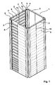
- FIG. 1 shows the cell 1 of a smooth wall silo, wherein at different points of the cell 1 of the smooth wall silo the formwork elements are omitted to illustrate the construction.
- the cell 1 has in detail four wall elements 2, which are connected in the corner region by connecting plates 3, 4.
- Each wall element 2 comprises two wall supports 5, which are connected by horizontally extending U-shaped transverse struts 6 ladder-shaped with each other.
- the arrangement of the U-shaped transverse struts is in this case such that the cross struts point with their open side in the installed state down.
- the ladder-shaped wall elements are clad by two mutually parallel shell elements 7 both on the inside and on the outside. Recognizable possess the shell elements each end a fold 7a, where - as in FIG. 1 recognizable, but especially in FIG. 3a shown - have the folds meandering notches 7b, so as to ensure that the formwork elements 7 can actually rest over the entire surface of the legs 6a of the cross braces 6.
- FIG. 3a a notch 7b of the fold 7a of the shell element 7;
- the transverse struts 6 for receiving the folds 7a of the formwork elements have a corresponding slot.
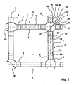
- the connecting plates 3 and 4 in the region of the support leg 3a, 4a also a fold 3b, 4b ( Fig. 2 )
- the above explanations apply mutatis mutandis to these folds.
- the transverse strut is designed in the region of a joint between two wall elements in the same way as in the area of a joint between a wall element and a connecting plate 3 or 4.
- the connecting plates 3, 4 have the support legs 3a, 4a, wherein the support legs 3a, 4a rests against the wall support 5.
- the support leg 3a, 4a has the end of the fold 3b, 4b, which forms a joint 15 in conjunction with the respective fold 7a of the shell element 7, which receives a vertically extending weld in the assembled state of the silo.
- each node column can be manufactured with identical corner connection plates.
- the open legs of such a node column can be closed by appropriately trained end plates 30, 35.
- end plates 30, 35 there is also the possibility to omit these end plates 30, 35, since the node columns need not be closed for reasons of stability, as has already been explained.
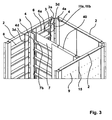
- an intermediate wall element 40 is provided, wherein the intermediate wall element 40 is formed exactly the same as the wall element 2.
- the connection of this intermediate wall element 40 to the wall element 2 is made in the same way with the known Eckitatisblechen 3, 4, as well as the formation of a node column is known. Only the support leg of the connecting plate is no longer in a wall on a support, but only on the cross struts. This works because of the intermediate wall 40 due to the wall supports 5 no vertical loads, but only horizontal loads are delivered to the wall 2.
- the formwork elements in the region of the transverse struts 6 are provided with openings 9 through which the formwork elements 7 are fixed to the transverse struts 6 by means of spot welds to form a shear bond. It has already been pointed out elsewhere that due to the notches 7b both the formwork elements 7 and the fold 3b, 4b of the connection plates, both the wall elements and the connection plates rest directly on the cross struts 6, so that when welding in the area the joint is directly connected to the underlying transverse strut 6.
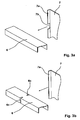
- FIG. 4 schematically, the arrangement of a horizontally extending square tube 45 is provided in the wall element 2, wherein on the square tube 45 as a funnel receptacle 46, a support plate is arranged.
- This support plate is connected for example by a weld with the horizontally extending square tube 45.
- the formwork elements 7 no longer run through, but continue upwards and downwards as independent wall elements.
Landscapes
- Engineering & Computer Science (AREA)
- Architecture (AREA)
- General Engineering & Computer Science (AREA)
- Civil Engineering (AREA)
- Structural Engineering (AREA)
- Filling Or Emptying Of Bunkers, Hoppers, And Tanks (AREA)
- Cyclones (AREA)
- Storage Of Harvested Produce (AREA)
Abstract
Description
Die vorliegende Erfindung betrifft eine Zelle für ein Glattwandsilo, die mehrere Wandelemente aufweist, die im Bereich ihrer Ecken durch Eckverbindungsbleche zur Bildung einer Knotensäule miteinander in Verbindung stehen, wobei das Eckverbindungsblech einen Stützenschenkel aufweist, der an seinem einen Ende einen abgewinkelten Verbindungsschenkel zur Verbindung mit einem benachbarten Verbindungsschenkel und an seinem anderen Ende eine Abkantung aufweist, wobei das Wandelement mindestens ein Schalelement aufweist.The present invention relates to a cell for a smooth-walled silo comprising a plurality of wall elements, which communicate in the region of their corners by corner connecting plates to form a node column with each other, wherein the corner connecting plate has a stanchion leg having at its one end an angled connecting leg for connection to a adjacent connecting leg and at its other end has a fold, wherein the wall element has at least one formwork element.
Silobehälter, und hier insbesondere auch Glattwandsilos der eingangs genannten Art sind aus dem Stand der Technik hinreichend bekannt. Solche Silobehälter dienen der Aufnahme unterschiedlichster Güter, wie z. B. Getreide oder auch Mehl. Glattwandsilos zeichnen sich im Einzelnen dadurch aus, dass diese im Wesentlichen keine horizontal verlaufenden Vorsprünge aufweisen, auf denen sich Lebensmittel, z. B. Mehl, ablagern könnten. Das heißt, wenn ein solcher Silo leer ist, dann ist er auch tatsächlich leer. Dies ist bei Silobehältern nicht der Fall, die trapezförmige Wandbleche aufweisen, wie z. B. Silobehälter gemäß der
Insofern ist bereits aus der DT 24 09 678 ein Glattwandsilobehälter bekannt, der sich dadurch auszeichnet, dass die Wände einer Zelle nicht mehr trapezförmig ausgebildet sind, sondern glatt. Zur Verbindung der einzelnen Wandelemente untereinander sind 90° Winkel bzw. auch Kopfbleche vorgesehen, die mit den Wandelementen verschraubt werden. Die Verschraubung erfolgt durch sogenannte Schraubbolzen, was bedeutet, dass ein solcher Silobehälter nicht unmittelbar an einer Gebäudewand zu montieren ist, da zumindest während der Montage zum Anziehen der Schrauben das Montagepersonal hinter die Silowand gelangen können muss. Ganz besonders problematisch stellt sich die Angelegenheit dann dar, wenn aus Stabilitätsgründen die einzelnen Wandelemente durch Stangen miteinander verbunden sind. Hieraus wird deutlich, dass die einzelnen Stützen durch diese Stangen miteinander in Verbindung stehen, wobei die Stangen kopfseitig eine Verschraubung aufweisen.In this respect, a smooth wall silo container is already known from DT 24 09 678, which is characterized in that the walls of a cell are no longer trapezoidal, but smooth. To connect the individual wall elements with each other 90 ° angle or head plates are provided, which are bolted to the wall elements. The screwing is done by so-called bolts, which means that such a silo container is not directly to be mounted on a building wall, as at least during assembly to tighten the screws, the assembly staff must be able to get behind the silo wall. Especially problematic, the matter is then, if for stability reasons, the individual wall elements are connected by rods. From this it is clear that the individual supports are connected by these rods with each other, the rods have a screw on the head side.
Aus der
Bereits an anderer Stelle wurde erläutert, dass ein Glattwandsilo im Bereich seines Inneren nach Möglichkeit so ausgebildet sein soll, dass sich vorzugsweise keine Vorsprünge oder Fugen ergeben, auf denen sich Reste des Silogutes, also z. B. Mehl, ablagern können. Betrachtet man in diesem Zusammenhang die
Aus der
Die der Erfindung zu Grunde liegende Aufgabe besteht demzufolge darin, ein Glattwandsilo, insbesondere ein Glattwandsilo umfassend mehrere Zellen bereitzustellen, das ohne Begrenzung durch das System bzw. das Konstruktionsprinzip als solches in beliebiger Höhe herstellbar ist, das im Wesentlichen unmittelbar an oder vor einer Wand aufgebaut werden kann, das hermetisch dicht und stabil ist und das darüber hinaus nur wenige unterschiedliche Bauteile benötigt.The object underlying the invention is therefore to provide a smooth wall silo, in particular a smooth wall silo comprising a plurality of cells, which can be produced without limitation by the system or the design principle as such in any amount, which is constructed substantially directly on or in front of a wall which is hermetically sealed and stable and, moreover, requires only a few different components.
Zur Lösung der Aufgabe wird erfindungsgemäß vorgeschlagen, dass ein jedes Wandelement endseitig jeweils eine im Einbauzustand vertikal verlaufende Wandstütze aufweist, wobei die beiden Wandstützen eines Stützenpaares eines Wandelements über ihre Höhe durch mehrere übereinander und beabstandet zueinander angeordnete Querstreben verbunden sind, wobei die Abkantung an einem Ende des Stützenschenkels in Richtung auf die Querstrebe zu gerichtet ist, wobei das Schalelement jeweils endseitig ebenfalls eine Abkantung aufweist, wobei die beiden Abkantungen in Eingriff mit den Querstreben stehen.To achieve the object, the invention proposes that each wall element end has in each case a vertical wall support in the installed state, wherein the two wall supports of a pair of supports of a wall element are connected over their height by a plurality of superimposed and spaced apart transverse struts, wherein the fold at one end the stanchion leg is directed in the direction of the transverse strut, wherein the shell element also has a fold at each end, wherein the two folds are in engagement with the transverse struts.
Durch die Anordnung von zwei im Einbauzustand vertikal verlaufenden Stützen in einem jeden Wandelement sind die einzelnen die Zelle oder den Silo bildenden Wände selbstständige Einheiten in dem Sinne, dass diese Wandelemente eine eigenständige Tragfunktion übernehmen. Dies ganz im Gegensatz zum Stand der Technik gemäß der
Wie bereits an anderer Stelle erläutert, weisen die Wandelemente im eingebauten Zustand zwei vertikal verlaufende Wandstützen auf. Diese Wandstützen sind durch Querstreben miteinander verbunden, wobei die Innenseite eines Wandelementes eines Silos durch Schalelemente verkleidet ist. Die Schalelemente selbst sind zu beiden Seiten mit Abkantungen versehen, wobei die Abkantungen der Schalelemente in Eingriff mit den Querstreben stehen. In gleicher Weise abgekantet sind auch die Eckverbindungsbleche, so dass im Bereich der Abkantungen zwischen den Eckverbindungsblechen einerseits und den Schalelementen andererseits Stöße entstehen, die durch senkrecht verlaufende Schweißnähte miteinander verbunden sind. Dadurch, dass die Schalelemente und die Eckverbindungsbleche durch die Abkantungen mit den Querstreben in Eingriff stehen, wird nun erreicht, dass diese beim Schweißen nur einen geringfügigen Verzug aufweisen. Dies ist wesentlich, wenn man davon ausgeht, dass durch Schweißnähte von mehreren Metern Länge ein erheblicher Wärmeeintrag erfolgt und insofern die Verzugsgefahr groß ist. Darüber hinaus dienen auch die Querstreben, die mit den senkrecht verlaufenden Wandstützen verbunden sind, und die darauf angeordneten Schalelemente der Stabilität eines solchen Wandelementes.As already explained elsewhere, the wall elements in the installed state on two vertically extending wall supports. These wall supports are interconnected by transverse struts, wherein the inside of a wall element of a silo is covered by formwork elements. The formwork elements themselves are provided on both sides with folds, wherein the folds of the formwork elements are in engagement with the cross struts. Bent in the same way are the Eckverbindungsbleche so that in the region of the folds between the Eckverbindungsblechen on the one hand and the formwork elements on the other hand shocks arise, which are interconnected by perpendicular welds. The fact that the formwork elements and the Eckverbindungsbleche by the folds with The cross struts are engaged, it is now achieved that they have only a slight delay during welding. This is essential if it is assumed that a considerable heat input takes place through welds of several meters in length and thus the risk of distortion is great. In addition, the cross struts, which are connected to the vertical wall supports, and the scarfing elements arranged thereon, the stability of such a wall element serve.
Zusammenfassend ist demzufolge festzuhalten, dass die Konstruktion ohne horizontale Verbindungen eine im Wesentlichen unbegrenzte Höhe erreichen kann. Das heißt, die Höhe ist systembedingt nicht begrenzt. Im Bereich der Stöße sind lange, gerade Schweißnähte vorgesehen, die mittels Traktorschweißvorrichtung hergestellt werden können. Ein solcher Silo kann im Wesentlichen unmittelbar vor einer vorhandenen Wand montiert werden, da die Knotensäulen hinten offen bleiben können.In summary, it should be noted that the construction without horizontal connections can reach a substantially unlimited height. That is, the height is not limited by the system. In the area of impacts, long, straight weld seams are provided, which can be produced by means of a tractor welding device. Such a silo can be mounted substantially immediately in front of an existing wall, since the nodal columns can remain open at the rear.
Des Weiteren kann durch die erfindungsgemäße Lehre ein Glattwandsilo mit mehreren Zellen hergestellt werden, wobei zwischen den Querstreben, Schalelementen und Ecketementen nicht nur eine dichte, sondern auch eine stabile Verbindung besteht.Furthermore, by the teaching of the invention, a smooth wall silo can be produced with a plurality of cells, wherein there is not only a dense, but also a stable connection between the cross struts, formwork elements and corner elements.
Vorteilhafte Merkmale der Erfindung ergeben sich aus den Unteransprüchen.Advantageous features of the invention will become apparent from the dependent claims.
So ist insbesondere vorgesehen, dass die Querstreben zur Erreichung einer hohen Stabilität nach Art eines U-Profils ausgebildet sind.Thus, it is provided in particular that the cross struts are designed to achieve a high stability in the manner of a U-profile.
Wie bereits an anderer Stelle erläutert, stehen sowohl die Eckverbindungsbleche als auch die Schalelemente durch Abkantungen in Eingriff mit den Querstreben. Im Einzelnen ist in diesem Zusammenhang vorgesehen, dass die beiden Abkantungen mit mäanderförmigen Ausklinkungen zum Erfassen der Querstreben im Bereich der Schenkel der Querstreben versehen sind. Das heißt, die Querstreben, die mit ihren geschlossenen Schenkeln nach außen zeigen, im eingebauten Zustand also nach unten hin offen sind, werden jeweils durch die Ausklinkung der Abkantungen der Schalelemente bzw. der Eckverbindungsbleche erfasst.As already explained elsewhere, both the Eckverbindungsbleche and the formwork elements are by bends in engagement with the cross struts. Specifically, it is provided in this context that the two folds with meandering Notches for detecting the transverse struts in the region of the legs of the cross struts are provided. In other words, the transverse struts, which point outwards with their closed legs, are thus open towards the bottom in the installed state, are respectively detected by the notch of the folds of the formwork elements or of the corner connecting plates.
Wie ebenfalls an anderer Stelle erläutert, ist im Bereich eines Stoßes zwischen den beiden Schalelementen oder auch zwischen einem Schalelement und einem Eckverbindungsblech eine vertikal verlaufende Schweißnaht angeordnet, was zur Folge hat, dass, da sowohl die Schalelemente als auch die Eckverbindungsbleche unmittelbar an den Schenkeln der Querstreben anliegen, beim Schweißvorgang durch den Stoß hindurch eine Verbindung mit den Schenkeln der Querstreben erfolgt.As also explained elsewhere, a vertically extending weld is arranged in the region of a joint between the two formwork elements or between a formwork element and a Eckverbindungsblech, with the result that, since both the formwork elements and the Eckverbindungsbleche directly to the legs of the Abut transverse struts, during the welding process through the joint through a connection with the legs of the cross struts takes place.
Alternativ kann auch vorgesehen sein, dass die Querstrebe im Bereich der Schenkel Schlitze zur Aufnahme der Abkantungen sowohl der Eckverbindungsbleche als auch der Schalelemente aufweist. Die Verbindung zwischen dem Schalelement und den Eckverbindungsblechen einerseits und den Querstreben andererseits durch eine im Bereich der Stöße angeordnete Schweißnaht kann dann allerdings nicht mehr sichergestellt werden. Insofern ist vorgesehen, dass die Schalelemente im Bereich der Querstreben Öffnungen aufweisen. Durch diese Öffnungen können die Schalelemente stoffschlüssig, z. B. durch Schweißpunkte, mit den Querstreben verbunden werden. Es sei an dieser Stelle ausdrücklich darauf hingewiesen, dass auch bei der Variante, bei der die Abkantungen mit mäanderförmigen Ausklinkungen versehen sind, um die Querstreben zu erfassen, solche Öffnungen an den Schalelementen im Bereich der Querstreben vorgesehen sein können, um eine innige Verbindung der Bauteile zueinander herzustellen. Generell gilt, dass mit Hilfe einer solchen Konstruktion durchaus erhebliche Schubkräfte in Wand längs- und - querrichtung aufgefangen werden können.Alternatively, it can also be provided that the cross strut in the region of the legs has slots for receiving the folds of both the Eckverbindungsbleche and the formwork elements. However, the connection between the formwork element and the Eckverbindungsblechen on the one hand and the crossbars on the other hand by a weld arranged in the region of the joints can then no longer be ensured. In this respect, it is provided that the formwork elements have openings in the region of the transverse struts. Through these openings, the shell elements can cohesively, z. B. by welding points, are connected to the cross braces. It should be expressly noted at this point that even in the variant in which the bends are provided with meandering notches to detect the cross braces, such openings may be provided on the formwork elements in the region of the transverse struts to an intimate connection of the components to produce each other. In general, with the help of such a construction, considerable shear forces in the longitudinal and transverse wall can be absorbed.
Nach einem weiteren Merkmal der Erfindung ist vorgesehen, dass der vom Stützenschenkel abgewinkelte Verbindungsarm des Eckverbindungsbleches einen Winkel zum Stützenschenkel des Eckverbindungsbleches von etwa 45° aufweist, wobei die beiden Verbindungsschenkel der Eckverbindungsbleche vorteilhaft einander überlappen und im Überlappungsbereich miteinander z. B. durch Schrauben verbunden sind.According to a further feature of the invention it is provided that the angled from the support leg connecting arm of the Eckverbindungsbleches an angle to the stanchion leg of Eckverbindungsbleches of about 45 °, wherein the two Connecting leg of the Eckverbindungsbleche advantageously overlap each other and in the overlapping area with each other z. B. are connected by screws.
Wie bereits an anderer Stelle erläutert, erfolgt die Verbindung zweier Wandelemente, die im Winkel von 90° zueinander stehen, im Bereich der Diagonalen der Eckverbindungsbleche, da hierdurch die Möglichkeit der Montage eines solchen Silos unmittelbar vor der Wand eröffnet wird, denn die Verschraubung kann vom Zelleninneren vorgenommen werden. Außerdem können durch eine solche diagonale Verbindung zweier Wandelemente hohe Zugkräfte übertragen werden.As already explained elsewhere, the connection of two wall elements, which are at an angle of 90 ° to each other, takes place in the region of the diagonals of the Eckverbindungsbleche, since this opens up the possibility of mounting such a silo immediately in front of the wall, because the screw can from Cell interior are made. In addition, high tensile forces can be transmitted by such a diagonal connection of two wall elements.
Nach einem weiteren Merkmal der Erfindung bildet der Stützenschenkel des Eckverbindungsbleches einen Teil des Mantels der Wandstütze. Hieraus wird deutlich, dass eine Wandstütze insgesamt als eigenständiges Vierkantrohr ausgebildet sein kann oder aber auch durch zwei parallel zueinander verlaufende Stützenschenkel zweier Eckverbindungsbleche, wobei dann die beiden Eckverbindungsbleche durch zwei parallel zueinander verlaufende Leisten zu einem Vierkant verbunden werden, um einem solchen Wandelement eine Stabilität zu verleihen, wie sie auch erzielbar ist, wenn als Wandstützen unmittelbar Vierkantrohre zur Anwendung gelangen.According to a further feature of the invention, the support leg of the Eckverbindungsbleches forms a part of the jacket of the wall support. It is clear that a wall support can be formed as a whole square tube or even by two mutually parallel support legs of two Eckverbindungsbleche, in which case the two Eckverbindungsbleche be connected by two mutually parallel bars to a square to such a wall element stability lend, as it can be achieved, when used as wall supports directly square tubes are used.
Die erfindungsgemäße Konstruktion hat insbesondere auch den Vorteil, dass mit den vorhandenen Konstruktionselementen, also insbesondere den Eckverbindungsblechen, eine Zelle an beliebiger Stelle durch weitere Wände unterteilt werden kann. Im Einzelnen ist in diesem Zusammenhang vorgesehen, dass zur Teilung einer Zelle ein Zwischenwandelement vorgesehen ist, wobei zur Verbindung des Zwischenwandelements mit dem Wandelement der Zelle die Eckverbindungsbleche an ihrer Abkantung im Stützenbereich mäanderförmige Ausklinkungen aufweisen, die in Eingriff mit den Querstreben des Wandelementes stehen. Nur der Vollständigkeit halber sei an dieser Stelle darauf hingewiesen, dass auch umgekehrt die Querstreben Schlitze zur Aufnahme der Abkantungen der Eckverbindungsbleche zeigen können, wie dies bereits an anderer Stelle beschrieben wurde. Hieraus wird deutlich, dass die erfindungsgemäße Konstruktion trotz der geringen Anzahl unterschiedlicher Bauelemente äußerst variabel ist.In particular, the construction according to the invention also has the advantage that a cell can be subdivided at any point by further walls with the existing construction elements, that is to say in particular the corner connecting plates. Specifically, it is provided in this context that an intermediate wall element is provided for dividing a cell, wherein for connecting the intermediate wall element with the wall element of the cell, the Eckverbindungsbleche have at their fold in the support area meandering notches, which are in engagement with the transverse struts of the wall element. Only the completeness It should be noted at this point that, conversely, the transverse struts can show slots for receiving the folds of the corner connecting plates, as has already been described elsewhere. It is clear from this that the construction according to the invention is extremely variable despite the small number of different components.
Nach einem weiteren Merkmal der Erfindung weist das Wandelement zur Anordnung einer Trichteraufnahme an dem Wandelement einer Zelle zumindest eine Querstrebe in Form eines Vierkantrohres auf, wobei an dem Vierkantrohr die Trichteraufnahme in Form eines winklig zum Wandelement verlaufenden Tragbleches angeordnet ist. Hieraus wird deutlich, dass durch Austausch einer Querstrebe in Form eines U-Profiles durch eine Querstrebe in Form eines Vierkantrohres die Möglichkeit eröffnet wird, an dieses Vierkantrohr dann das Tragblech der Trichteraufnahme anzubringen. Durch den Austausch einer U-förmig ausgebildeten Querstrebe mit einem Vierkantrohr als Querstrebe ist lediglich erforderlich, dass die Ausklinkungen bei den Abkantungen im Bereich des horizontal verlaufenden Vierkantrohres den Abmessungen dieses Vierkantrohres entsprechen.According to a further feature of the invention, the wall element for arranging a funnel receptacle on the wall element of a cell on at least one transverse strut in the form of a square tube, wherein on the square tube, the funnel receptacle is arranged in the form of an angle to the wall element extending support plate. From this it is clear that the possibility is opened by replacing a cross member in the form of a U-profile by a cross strut in the form of a square tube, then attach the support plate of the funnel holder to this square tube. By replacing a U-shaped cross member with a square tube as a cross member is only necessary that the notches correspond to the dimensions of this square tube at the bends in the region of the horizontally extending square tube.
Anhand der Zeichnungen wird die Erfindung nachstehend beispielhaft näher erläutert.
Figur 1- zeigt eine Zelle eines Glattwandsilos in perspektivischer Darstellung;
Figur 2- zeigt einen Schnitt durch die Zelle eines Silobehälters, wobei die Knotensäulen entsprechend der Anbindung der Wandelemente jeweils unterschiedlich ausgebildet sind;
Figur 3- zeigt eine Ausführungsform einer Zelle eines Silos mit einer Zwischenwand;
Figur 3a- zeigt die Einzelheit "X" mit einer Ausklinkung der Abkantung des Eckverbindungsbleches;
Figur 3b- zeigt eine Darstellung gemäß
Figur 3a , wobei jedoch die Querstrebe zur Aufnahme der Abkantung des Eckverbindungsbleches einen Schlitz aufweist; Figur 4- zeigt schematisch die Anordnung einer Trichteraufnahme an einem Wandelement.
- FIG. 1
- shows a cell of a smooth wall silos in perspective view;
- FIG. 2
- shows a section through the cell of a silo container, wherein the node columns are each formed differently according to the connection of the wall elements;
- FIG. 3
- shows an embodiment of a cell of a silo with an intermediate wall;
- FIG. 3a
- shows the detail "X" with a notch of the fold of the Eckverbindungsbleches;
- FIG. 3b
- shows a representation according to
FIG. 3a but wherein the cross member for receiving the fold of the Eckverbindungsbleches has a slot; - FIG. 4
- shows schematically the arrangement of a funnel receptacle on a wall element.
Wie bereits ausgeführt, zeigt die
Zur Bildung einer Knotensäule mit mehreren abgehenden Wandelementen dienen die bereits zuvor erwähnten Verbindungsbleche 3, 4. Die Verbindungsbleche 3, 4 weisen den Stützenschenkel 3a, 4a auf, wobei der Stützenschenkel 3a, 4a an der Wandstütze 5 anliegt. Der Stützenschenkel 3a, 4a weist endseitig die Abkantung 3b, 4b auf, die in Verbindung mit der jeweiligen Abkantung 7a des Schalelementes 7 einen Stoß 15 bildet, der im aufgebauten Zustand des Silos eine vertikal verlaufende Schweißnaht aufnimmt.To form a node column with a plurality of outgoing wall elements serve the previously mentioned connecting
Wesentlich ist nun, dass die Eckverbindungsbleche 3, 4 einander im Bereich der Diagonalen 21 mit den jeweiligen Verbindungsschenkeln 3c, 4c überlappen. Im Bereich der Überlappung 21 kann die Verbindung der beiden Eckverbindungsbleche 3, 4 im Bereich der Verbindungsschenkel durch Schrauben erfolgen.It is essential that the
Wie bereits an anderer Stelle erläutert, kann eine jede Knotensäule, egal wie viele Wandelemente von dieser Knotensäule abgehen, mit identischen Eckverbindungsblechen hergestellt werden. Die offenen Schenkel einer solchen Knotensäule können durch entsprechend ausgebildete Abschlussbleche 30, 35 verschlossen werden. Es besteht allerdings auch die Möglichkeit, diese Abschlussbleche 30, 35 wegzulassen, da die Knotensäulen aus Stabilitätsgründen nicht geschlossen sein müssen, wie dies bereits erläutert wurde. Es können ebenfalls die Verbindungsschenkel 3c, 4c weggelassen werden oder in Richtung auf das Innere der Knotensäule abgewinkelt sein.As already explained elsewhere, no matter how many wall elements depart from this node column, each node column can be manufactured with identical corner connection plates. The open legs of such a node column can be closed by appropriately trained
Gemäß
Wie insbesondere aus
Bei der Ausführungsform gemäß
Gemäß
Claims (12)
- A cell (1) for a smooth wall silo, which comprises several wall elements (2) that are joined together by corner connecting sheets (3, 4) in the region of their corners in order to form a node pillar, said corner connecting sheet (3, 4) comprising a pillar leg (3a, 4a) that comprises at its one end an angled connecting leg (3c, 4c) for connection to a neighboring connecting leg (3c, 4c) and that comprises at its other end a chamfer (3b, 4b), said wall element (2) comprising at least one casing element (7),
characterized in
that each wall element (2) comprises on either end side a wall pillar (5) extending vertically when mounted, said two wall pillars (5) of a pair of pillars of a wall element (2) being connected over their height through several cross beams (6) disposed one above the other in a spaced-apart relationship, the chamfers (3b, 4b) at one end of the pillar leg (3a, 4a) being oriented toward said cross beam (6), the casing element also comprising respectively a chamfer (7a) at the end side, the two chamfers (7; 3b, 4b) being engaged with said cross beams (6). - The cell for a smooth wall silo as set forth in claim 1,
characterized in
that the cross beams (6) are configured in the fashion of a U profile. - The cell for a smooth wall silo as set forth in claim 1,
characterized in
that the two chamfers (7; 3b, 4b) are provided with meander-shaped notches (7b, 3d, 4d) for taking hold of the cross beams (6) in the region of the legs of the cross beams (6). - The cell for a smooth wall silo as set forth in claim 1,
characterized in
that the cross beam (6) comprises, in the region of the leg, slots (6c) for receiving the chamfers (7; 3b, 4b). - The cell for a smooth wall silo as set forth in claim 1,
characterized in
that, in case of a wall element (2) having several, in particular two, parallel casing elements (7), the casing elements (7) comprise chamfers (7a) for taking hold of the cross beams in the region of their butt joint (15). - The cell for a smooth wall silo as set forth in any one of the afore mentioned claims,
characterized in
that the connecting leg (3c, 4c) of the corner connecting sheet (3, 4), which is angled from the pillar leg (3a, 4a), is inclined at an angle of about 45° with respect to the pillar leg of the corner connecting sheet. - The cell for a smooth wall silo as set forth in any one of the afore mentioned claims,
characterized in
that, to build a cell (1), two corner connecting sheets (3, 4), which are connected together, comprise one connecting leg (3c, 4c) each, said connecting legs (3c, 4c) overlapping each other and being connected together in the region of the overlap (at 21) such as by screws. - The cell for a smooth wall silo as set forth in any one of the afore mentioned claims,
characterized in
that the pillar leg (3a, 4a) of the corner connecting sheet (3, 4) forms a part of the surface area of the wall pillar (5). - The cell for a smooth wall silo as set forth in any one of the afore mentioned claims,
characterized in
that there is provided a partitioning wall element (40) for partitioning a cell (1), the corner connecting sheets (3, 4) comprising at their chamfer (3b, 4b) meander-shaped notches (3d, 4d) in the region of the pillar, said notches engaging the cross beams (6) of the wall element (2) for connecting the partitioning wall element (40) to the wall element (2) of the cell (1). - The cell for a smooth wall silo as set forth in any one of the afore mentioned claims,
characterized in
that, in order to arrange a funnel feeder on the wall element (2) of a cell (1), the wall element (2) comprises at least one cross beam in the shape of a square tube (45), the funnel feeder (46) in the shape of a carrying sheet extending at an angle with respect to the wall element being disposed on said square tube (45). - The cell for a smooth wall silo as set forth in any one of the afore mentioned claims,
characterized in
that the casing elements (7) comprise openings (9) in the region of the cross beams (6). - A smooth wall silo with several cells as set forth in one or several of the afore mentioned claims.
Priority Applications (5)
| Application Number | Priority Date | Filing Date | Title |
|---|---|---|---|
| DK07010472T DK1995397T3 (en) | 2007-05-25 | 2007-05-25 | Smooth Wall Silo |
| DE502007000905T DE502007000905D1 (en) | 2007-05-25 | 2007-05-25 | smooth wall silo |
| PL07010472T PL1995397T3 (en) | 2007-05-25 | 2007-05-25 | Smooth wall silo |
| AT07010472T ATE434098T1 (en) | 2007-05-25 | 2007-05-25 | SMOOTH WALL SILO |
| EP07010472A EP1995397B1 (en) | 2007-05-25 | 2007-05-25 | Smooth wall silo |
Applications Claiming Priority (1)
| Application Number | Priority Date | Filing Date | Title |
|---|---|---|---|
| EP07010472A EP1995397B1 (en) | 2007-05-25 | 2007-05-25 | Smooth wall silo |
Publications (2)
| Publication Number | Publication Date |
|---|---|
| EP1995397A1 EP1995397A1 (en) | 2008-11-26 |
| EP1995397B1 true EP1995397B1 (en) | 2009-06-17 |
Family
ID=38596790
Family Applications (1)
| Application Number | Title | Priority Date | Filing Date |
|---|---|---|---|
| EP07010472A Not-in-force EP1995397B1 (en) | 2007-05-25 | 2007-05-25 | Smooth wall silo |
Country Status (5)
| Country | Link |
|---|---|
| EP (1) | EP1995397B1 (en) |
| AT (1) | ATE434098T1 (en) |
| DE (1) | DE502007000905D1 (en) |
| DK (1) | DK1995397T3 (en) |
| PL (1) | PL1995397T3 (en) |
Families Citing this family (5)
| Publication number | Priority date | Publication date | Assignee | Title |
|---|---|---|---|---|
| DE202016104178U1 (en) | 2016-07-29 | 2017-11-02 | Markus Becker | silo |
| PL127198U1 (en) * | 2018-03-30 | 2019-10-07 | Aqua World Spółka Z Ograniczoną Odpowiedzialnością | Structure strengthening plastic tanks, consisting of closed section metal straps and plastic supports |
| PL71419Y1 (en) * | 2018-03-30 | 2020-05-18 | Aqua World Spolka Z Ograniczona Odpowiedzialnoscia | Structure strengthening plastic tanks, consisting of closed section metal straps and plastic ribs |
| PL71418Y1 (en) * | 2018-03-30 | 2020-05-18 | Aqua World Spolka Z Ograniczona Odpowiedzialnoscia | Structure strengthening plastic tanks, consisting of open section metal straps and plastic ribs |
| PL127197U1 (en) * | 2018-03-30 | 2019-10-07 | Aqua World Spółka Z Ograniczoną Odpowiedzialnością | Structure strengthening plastic tanks, consisting of open section metal straps and plastic supports |
Family Cites Families (5)
| Publication number | Priority date | Publication date | Assignee | Title |
|---|---|---|---|---|
| BE694416A (en) | 1967-02-22 | 1967-07-31 | ||
| GB1217732A (en) * | 1968-04-01 | 1970-12-31 | Philip Harry Collier | Improvements in wall structures for storage bins |
| AT360911B (en) | 1979-03-07 | 1980-02-10 | Geroldinger Walter Ohg | CELL SILO |
| DE3002782C2 (en) | 1980-01-26 | 1982-01-28 | Industriebau und Wärmetechnik GmbH, 8670 Hof | Support for a cell silo |
| EP0907587B1 (en) * | 1996-04-18 | 2000-01-12 | Rionde S.A. | Wall or casing made of metal sheets stretched over a frame or structure, and construction procedure |
-
2007
- 2007-05-25 PL PL07010472T patent/PL1995397T3/en unknown
- 2007-05-25 DK DK07010472T patent/DK1995397T3/en active
- 2007-05-25 AT AT07010472T patent/ATE434098T1/en active
- 2007-05-25 DE DE502007000905T patent/DE502007000905D1/en active Active
- 2007-05-25 EP EP07010472A patent/EP1995397B1/en not_active Not-in-force
Also Published As
| Publication number | Publication date |
|---|---|
| DE502007000905D1 (en) | 2009-07-30 |
| PL1995397T3 (en) | 2009-10-30 |
| DK1995397T3 (en) | 2009-07-27 |
| ATE434098T1 (en) | 2009-07-15 |
| EP1995397A1 (en) | 2008-11-26 |
Similar Documents
| Publication | Publication Date | Title |
|---|---|---|
| EP2090744B1 (en) | Conveyor trolley | |
| DE1903129B2 (en) | Device for connecting a beam to a concrete column | |
| EP1995397B1 (en) | Smooth wall silo | |
| EP2072685A1 (en) | Foundation structure for an offshore construction, in particular an offshore wind energy system, and method for manufacture thereof | |
| EP2455305B1 (en) | Silo | |
| DE202007003206U1 (en) | Modular carrier for roofs of large areas | |
| AT502604B1 (en) | COMPOSITE SUPPORT FOR KNOT CONNECTIONS OF CONSTRUCTION WORKS AND BUILDING TIE | |
| EP2060680A1 (en) | Support for flood defence wall | |
| DE3837475C1 (en) | ||
| DE3923613C2 (en) | System element for a combined tubular filling and removal shaft | |
| DE2209484C3 (en) | Pressure-resistant transcontainer for flowable goods | |
| DE202013104353U1 (en) | Overhead conveyor for storage on the ceiling of an assembly plant | |
| DE102006044790A1 (en) | Bridge with two trussed discs and kit for their production | |
| DE1259553B (en) | Silo or similar structure with walls made of columns and corrugated sheet metal | |
| AT391342B (en) | Side-wall element, preferably consisting of sheet steel, for erecting self-supporting silo-container casing walls | |
| DE1684837C3 (en) | Sheet steel silo made of double-shell wall elements | |
| DE1892804U (en) | COMPONENT SET FOR STEEL SILOS IN CELL CONSTRUCTION. | |
| DE3444645C2 (en) | ||
| DE3840805A1 (en) | Container which can be assembled and dismantled quickly | |
| DE2853325C2 (en) | Upper part for silos | |
| DE1684898C3 (en) | Panel-like structural element for the walls of containers, in particular silos | |
| DE8330257U1 (en) | DOUBLE-WALLED STEEL PANEL | |
| DE202016104178U1 (en) | silo | |
| DE202005006228U1 (en) | Roof construction for buildings, especially industrial buildings with large widths, comprises bottom and top booms in the form of I-shaped supports with two boom flanges, and node elements with two flat node flange plates | |
| DE102020110043A1 (en) | silo |
Legal Events
| Date | Code | Title | Description |
|---|---|---|---|
| PUAI | Public reference made under article 153(3) epc to a published international application that has entered the european phase |
Free format text: ORIGINAL CODE: 0009012 |
|
| 17P | Request for examination filed |
Effective date: 20071227 |
|
| AK | Designated contracting states |
Kind code of ref document: A1 Designated state(s): AT BE BG CH CY CZ DE DK EE ES FI FR GB GR HU IE IS IT LI LT LU LV MC MT NL PL PT RO SE SI SK TR |
|
| AX | Request for extension of the european patent |
Extension state: AL BA HR MK RS |
|
| GRAP | Despatch of communication of intention to grant a patent |
Free format text: ORIGINAL CODE: EPIDOSNIGR1 |
|
| GRAS | Grant fee paid |
Free format text: ORIGINAL CODE: EPIDOSNIGR3 |
|
| GRAA | (expected) grant |
Free format text: ORIGINAL CODE: 0009210 |
|
| AK | Designated contracting states |
Kind code of ref document: B1 Designated state(s): AT BE BG CH CY CZ DE DK EE ES FI FR GB GR HU IE IS IT LI LT LU LV MC MT NL PL PT RO SE SI SK TR |
|
| REG | Reference to a national code |
Ref country code: GB Ref legal event code: FG4D Free format text: NOT ENGLISH |
|
| REG | Reference to a national code |
Ref country code: CH Ref legal event code: EP |
|
| REG | Reference to a national code |
Ref country code: IE Ref legal event code: FG4D Free format text: LANGUAGE OF EP DOCUMENT: GERMAN |
|
| REG | Reference to a national code |
Ref country code: DK Ref legal event code: T3 |
|
| AKX | Designation fees paid |
Designated state(s): AT BE BG CH CY CZ DE DK EE ES FI FR GB GR HU IE IS IT LI LT LU LV MC MT NL PL PT RO SE SI SK TR |
|
| REF | Corresponds to: |
Ref document number: 502007000905 Country of ref document: DE Date of ref document: 20090730 Kind code of ref document: P |
|
| REG | Reference to a national code |
Ref country code: CH Ref legal event code: NV Representative=s name: R. A. EGLI & CO. PATENTANWAELTE |
|
| PG25 | Lapsed in a contracting state [announced via postgrant information from national office to epo] |
Ref country code: LT Free format text: LAPSE BECAUSE OF FAILURE TO SUBMIT A TRANSLATION OF THE DESCRIPTION OR TO PAY THE FEE WITHIN THE PRESCRIBED TIME-LIMIT Effective date: 20090617 Ref country code: FI Free format text: LAPSE BECAUSE OF FAILURE TO SUBMIT A TRANSLATION OF THE DESCRIPTION OR TO PAY THE FEE WITHIN THE PRESCRIBED TIME-LIMIT Effective date: 20090617 |
|
| REG | Reference to a national code |
Ref country code: PL Ref legal event code: T3 |
|
| PG25 | Lapsed in a contracting state [announced via postgrant information from national office to epo] |
Ref country code: SE Free format text: LAPSE BECAUSE OF FAILURE TO SUBMIT A TRANSLATION OF THE DESCRIPTION OR TO PAY THE FEE WITHIN THE PRESCRIBED TIME-LIMIT Effective date: 20090917 Ref country code: SI Free format text: LAPSE BECAUSE OF FAILURE TO SUBMIT A TRANSLATION OF THE DESCRIPTION OR TO PAY THE FEE WITHIN THE PRESCRIBED TIME-LIMIT Effective date: 20090617 Ref country code: LV Free format text: LAPSE BECAUSE OF FAILURE TO SUBMIT A TRANSLATION OF THE DESCRIPTION OR TO PAY THE FEE WITHIN THE PRESCRIBED TIME-LIMIT Effective date: 20090617 |
|
| REG | Reference to a national code |
Ref country code: IE Ref legal event code: FD4D |
|
| PG25 | Lapsed in a contracting state [announced via postgrant information from national office to epo] |
Ref country code: IE Free format text: LAPSE BECAUSE OF FAILURE TO SUBMIT A TRANSLATION OF THE DESCRIPTION OR TO PAY THE FEE WITHIN THE PRESCRIBED TIME-LIMIT Effective date: 20090617 Ref country code: EE Free format text: LAPSE BECAUSE OF FAILURE TO SUBMIT A TRANSLATION OF THE DESCRIPTION OR TO PAY THE FEE WITHIN THE PRESCRIBED TIME-LIMIT Effective date: 20090617 Ref country code: RO Free format text: LAPSE BECAUSE OF FAILURE TO SUBMIT A TRANSLATION OF THE DESCRIPTION OR TO PAY THE FEE WITHIN THE PRESCRIBED TIME-LIMIT Effective date: 20090617 Ref country code: IS Free format text: LAPSE BECAUSE OF FAILURE TO SUBMIT A TRANSLATION OF THE DESCRIPTION OR TO PAY THE FEE WITHIN THE PRESCRIBED TIME-LIMIT Effective date: 20091017 Ref country code: ES Free format text: LAPSE BECAUSE OF FAILURE TO SUBMIT A TRANSLATION OF THE DESCRIPTION OR TO PAY THE FEE WITHIN THE PRESCRIBED TIME-LIMIT Effective date: 20090928 |
|
| PG25 | Lapsed in a contracting state [announced via postgrant information from national office to epo] |
Ref country code: SK Free format text: LAPSE BECAUSE OF FAILURE TO SUBMIT A TRANSLATION OF THE DESCRIPTION OR TO PAY THE FEE WITHIN THE PRESCRIBED TIME-LIMIT Effective date: 20090617 |
|
| PG25 | Lapsed in a contracting state [announced via postgrant information from national office to epo] |
Ref country code: PT Free format text: LAPSE BECAUSE OF FAILURE TO SUBMIT A TRANSLATION OF THE DESCRIPTION OR TO PAY THE FEE WITHIN THE PRESCRIBED TIME-LIMIT Effective date: 20091017 Ref country code: BG Free format text: LAPSE BECAUSE OF FAILURE TO SUBMIT A TRANSLATION OF THE DESCRIPTION OR TO PAY THE FEE WITHIN THE PRESCRIBED TIME-LIMIT Effective date: 20090917 |
|
| PLBE | No opposition filed within time limit |
Free format text: ORIGINAL CODE: 0009261 |
|
| STAA | Information on the status of an ep patent application or granted ep patent |
Free format text: STATUS: NO OPPOSITION FILED WITHIN TIME LIMIT |
|
| 26N | No opposition filed |
Effective date: 20100318 |
|
| PG25 | Lapsed in a contracting state [announced via postgrant information from national office to epo] |
Ref country code: GR Free format text: LAPSE BECAUSE OF FAILURE TO SUBMIT A TRANSLATION OF THE DESCRIPTION OR TO PAY THE FEE WITHIN THE PRESCRIBED TIME-LIMIT Effective date: 20090918 |
|
| PG25 | Lapsed in a contracting state [announced via postgrant information from national office to epo] |
Ref country code: MC Free format text: LAPSE BECAUSE OF NON-PAYMENT OF DUE FEES Effective date: 20100531 |
|
| PG25 | Lapsed in a contracting state [announced via postgrant information from national office to epo] |
Ref country code: IT Free format text: LAPSE BECAUSE OF NON-PAYMENT OF DUE FEES Effective date: 20100525 |
|
| PG25 | Lapsed in a contracting state [announced via postgrant information from national office to epo] |
Ref country code: MT Free format text: LAPSE BECAUSE OF FAILURE TO SUBMIT A TRANSLATION OF THE DESCRIPTION OR TO PAY THE FEE WITHIN THE PRESCRIBED TIME-LIMIT Effective date: 20090617 |
|
| PG25 | Lapsed in a contracting state [announced via postgrant information from national office to epo] |
Ref country code: CY Free format text: LAPSE BECAUSE OF FAILURE TO SUBMIT A TRANSLATION OF THE DESCRIPTION OR TO PAY THE FEE WITHIN THE PRESCRIBED TIME-LIMIT Effective date: 20090617 |
|
| PG25 | Lapsed in a contracting state [announced via postgrant information from national office to epo] |
Ref country code: LU Free format text: LAPSE BECAUSE OF NON-PAYMENT OF DUE FEES Effective date: 20100525 Ref country code: HU Free format text: LAPSE BECAUSE OF FAILURE TO SUBMIT A TRANSLATION OF THE DESCRIPTION OR TO PAY THE FEE WITHIN THE PRESCRIBED TIME-LIMIT Effective date: 20091218 |
|
| PG25 | Lapsed in a contracting state [announced via postgrant information from national office to epo] |
Ref country code: TR Free format text: LAPSE BECAUSE OF FAILURE TO SUBMIT A TRANSLATION OF THE DESCRIPTION OR TO PAY THE FEE WITHIN THE PRESCRIBED TIME-LIMIT Effective date: 20090617 |
|
| PGFP | Annual fee paid to national office [announced via postgrant information from national office to epo] |
Ref country code: GB Payment date: 20140521 Year of fee payment: 8 |
|
| PGFP | Annual fee paid to national office [announced via postgrant information from national office to epo] |
Ref country code: CH Payment date: 20140521 Year of fee payment: 8 Ref country code: FR Payment date: 20140527 Year of fee payment: 8 Ref country code: IT Payment date: 20140527 Year of fee payment: 8 Ref country code: NL Payment date: 20140521 Year of fee payment: 8 |
|
| PGFP | Annual fee paid to national office [announced via postgrant information from national office to epo] |
Ref country code: PL Payment date: 20140424 Year of fee payment: 8 Ref country code: DK Payment date: 20140521 Year of fee payment: 8 Ref country code: BE Payment date: 20140523 Year of fee payment: 8 |
|
| REG | Reference to a national code |
Ref country code: DK Ref legal event code: EBP Effective date: 20150531 |
|
| REG | Reference to a national code |
Ref country code: CH Ref legal event code: PL |
|
| GBPC | Gb: european patent ceased through non-payment of renewal fee |
Effective date: 20150525 |
|
| PG25 | Lapsed in a contracting state [announced via postgrant information from national office to epo] |
Ref country code: LI Free format text: LAPSE BECAUSE OF NON-PAYMENT OF DUE FEES Effective date: 20150531 Ref country code: IT Free format text: LAPSE BECAUSE OF NON-PAYMENT OF DUE FEES Effective date: 20150525 Ref country code: CH Free format text: LAPSE BECAUSE OF NON-PAYMENT OF DUE FEES Effective date: 20150531 |
|
| REG | Reference to a national code |
Ref country code: NL Ref legal event code: MM Effective date: 20150601 |
|
| REG | Reference to a national code |
Ref country code: FR Ref legal event code: ST Effective date: 20160129 |
|
| PG25 | Lapsed in a contracting state [announced via postgrant information from national office to epo] |
Ref country code: NL Free format text: LAPSE BECAUSE OF NON-PAYMENT OF DUE FEES Effective date: 20150601 Ref country code: GB Free format text: LAPSE BECAUSE OF NON-PAYMENT OF DUE FEES Effective date: 20150525 Ref country code: DK Free format text: LAPSE BECAUSE OF NON-PAYMENT OF DUE FEES Effective date: 20150531 |
|
| PG25 | Lapsed in a contracting state [announced via postgrant information from national office to epo] |
Ref country code: FR Free format text: LAPSE BECAUSE OF NON-PAYMENT OF DUE FEES Effective date: 20150601 |
|
| PG25 | Lapsed in a contracting state [announced via postgrant information from national office to epo] |
Ref country code: PL Free format text: LAPSE BECAUSE OF NON-PAYMENT OF DUE FEES Effective date: 20150525 |
|
| PG25 | Lapsed in a contracting state [announced via postgrant information from national office to epo] |
Ref country code: BE Free format text: LAPSE BECAUSE OF NON-PAYMENT OF DUE FEES Effective date: 20150531 |
|
| PGFP | Annual fee paid to national office [announced via postgrant information from national office to epo] |
Ref country code: CZ Payment date: 20220523 Year of fee payment: 16 |
|
| PGFP | Annual fee paid to national office [announced via postgrant information from national office to epo] |
Ref country code: AT Payment date: 20220523 Year of fee payment: 16 |
|
| PGFP | Annual fee paid to national office [announced via postgrant information from national office to epo] |
Ref country code: DE Payment date: 20220627 Year of fee payment: 16 |
|
| REG | Reference to a national code |
Ref country code: DE Ref legal event code: R119 Ref document number: 502007000905 Country of ref document: DE |
|
| REG | Reference to a national code |
Ref country code: AT Ref legal event code: MM01 Ref document number: 434098 Country of ref document: AT Kind code of ref document: T Effective date: 20230525 |
|
| PG25 | Lapsed in a contracting state [announced via postgrant information from national office to epo] |
Ref country code: CZ Free format text: LAPSE BECAUSE OF NON-PAYMENT OF DUE FEES Effective date: 20230525 Ref country code: AT Free format text: LAPSE BECAUSE OF NON-PAYMENT OF DUE FEES Effective date: 20230525 |
|
| PG25 | Lapsed in a contracting state [announced via postgrant information from national office to epo] |
Ref country code: DE Free format text: LAPSE BECAUSE OF NON-PAYMENT OF DUE FEES Effective date: 20231201 |