EP1995083B1 - Verfahren und Vorrichtung zum Bestimmen der geometrischen Abmessungen eines Fahrzeugrades mittels optischer Sensoren - Google Patents
Verfahren und Vorrichtung zum Bestimmen der geometrischen Abmessungen eines Fahrzeugrades mittels optischer Sensoren Download PDFInfo
- Publication number
- EP1995083B1 EP1995083B1 EP07010263A EP07010263A EP1995083B1 EP 1995083 B1 EP1995083 B1 EP 1995083B1 EP 07010263 A EP07010263 A EP 07010263A EP 07010263 A EP07010263 A EP 07010263A EP 1995083 B1 EP1995083 B1 EP 1995083B1
- Authority
- EP
- European Patent Office
- Prior art keywords
- rim
- wheel
- fitting
- sensing
- light beam
- Prior art date
- Legal status (The legal status is an assumption and is not a legal conclusion. Google has not performed a legal analysis and makes no representation as to the accuracy of the status listed.)
- Active
Links
Images


Classifications
-
- B—PERFORMING OPERATIONS; TRANSPORTING
- B60—VEHICLES IN GENERAL
- B60C—VEHICLE TYRES; TYRE INFLATION; TYRE CHANGING; CONNECTING VALVES TO INFLATABLE ELASTIC BODIES IN GENERAL; DEVICES OR ARRANGEMENTS RELATED TO TYRES
- B60C25/00—Apparatus or tools adapted for mounting, removing or inspecting tyres
- B60C25/01—Apparatus or tools adapted for mounting, removing or inspecting tyres for removing tyres from or mounting tyres on wheels
- B60C25/05—Machines
- B60C25/132—Machines for removing and mounting tyres
- B60C25/135—Machines for removing and mounting tyres having a tyre support or a tool, movable along wheel axis
- B60C25/138—Machines for removing and mounting tyres having a tyre support or a tool, movable along wheel axis with rotary motion of tool or tyre support
-
- B—PERFORMING OPERATIONS; TRANSPORTING
- B60—VEHICLES IN GENERAL
- B60C—VEHICLE TYRES; TYRE INFLATION; TYRE CHANGING; CONNECTING VALVES TO INFLATABLE ELASTIC BODIES IN GENERAL; DEVICES OR ARRANGEMENTS RELATED TO TYRES
- B60C25/00—Apparatus or tools adapted for mounting, removing or inspecting tyres
- B60C25/01—Apparatus or tools adapted for mounting, removing or inspecting tyres for removing tyres from or mounting tyres on wheels
- B60C25/05—Machines
- B60C25/0548—Machines equipped with sensing means, e.g. for positioning, measuring or controlling
- B60C25/0554—Machines equipped with sensing means, e.g. for positioning, measuring or controlling optical, e.g. cameras
-
- G—PHYSICS
- G01—MEASURING; TESTING
- G01B—MEASURING LENGTH, THICKNESS OR SIMILAR LINEAR DIMENSIONS; MEASURING ANGLES; MEASURING AREAS; MEASURING IRREGULARITIES OF SURFACES OR CONTOURS
- G01B11/00—Measuring arrangements characterised by the use of optical techniques
- G01B11/24—Measuring arrangements characterised by the use of optical techniques for measuring contours or curvatures
- G01B11/245—Measuring arrangements characterised by the use of optical techniques for measuring contours or curvatures using a plurality of fixed, simultaneously operating transducers
-
- G—PHYSICS
- G01—MEASURING; TESTING
- G01B—MEASURING LENGTH, THICKNESS OR SIMILAR LINEAR DIMENSIONS; MEASURING ANGLES; MEASURING AREAS; MEASURING IRREGULARITIES OF SURFACES OR CONTOURS
- G01B11/00—Measuring arrangements characterised by the use of optical techniques
- G01B11/24—Measuring arrangements characterised by the use of optical techniques for measuring contours or curvatures
- G01B11/25—Measuring arrangements characterised by the use of optical techniques for measuring contours or curvatures by projecting a pattern, e.g. one or more lines, moiré fringes on the object
- G01B11/2513—Measuring arrangements characterised by the use of optical techniques for measuring contours or curvatures by projecting a pattern, e.g. one or more lines, moiré fringes on the object with several lines being projected in more than one direction, e.g. grids, patterns
-
- G—PHYSICS
- G01—MEASURING; TESTING
- G01M—TESTING STATIC OR DYNAMIC BALANCE OF MACHINES OR STRUCTURES; TESTING OF STRUCTURES OR APPARATUS, NOT OTHERWISE PROVIDED FOR
- G01M17/00—Testing of vehicles
- G01M17/007—Wheeled or endless-tracked vehicles
- G01M17/013—Wheels
-
- B—PERFORMING OPERATIONS; TRANSPORTING
- B60—VEHICLES IN GENERAL
- B60C—VEHICLE TYRES; TYRE INFLATION; TYRE CHANGING; CONNECTING VALVES TO INFLATABLE ELASTIC BODIES IN GENERAL; DEVICES OR ARRANGEMENTS RELATED TO TYRES
- B60C25/00—Apparatus or tools adapted for mounting, removing or inspecting tyres
- B60C25/01—Apparatus or tools adapted for mounting, removing or inspecting tyres for removing tyres from or mounting tyres on wheels
- B60C25/05—Machines
- B60C25/0527—Adapting to different wheel diameters, i.e. distance between support and tool
-
- G—PHYSICS
- G05—CONTROLLING; REGULATING
- G05B—CONTROL OR REGULATING SYSTEMS IN GENERAL; FUNCTIONAL ELEMENTS OF SUCH SYSTEMS; MONITORING OR TESTING ARRANGEMENTS FOR SUCH SYSTEMS OR ELEMENTS
- G05B2219/00—Program-control systems
- G05B2219/30—Nc systems
- G05B2219/37—Measurements
- G05B2219/37048—Split beam, stripe projection on object, lines detected with cameras
Definitions
- the invention concerns a method of and apparatus for fitting or removing a motor vehicle wheel tyre according to the preambles of claims 1 and 10.
- a rim of a motor vehicle wheel is fixed on wheel receiving means of a tyre changer.
- An imaging sensor assembly is associated with a tyre removal arm and includes a light source which can emit a planar light beam and an imaging sensor which receives the reflected light beam. Images and distance measurements obtained from the imaging sensor assembly are utilized to locate bead rollers into an appropriate junction for displacement of the tyre from the bead seat surfaces.
- EP-A-1 479 538 discloses an apparatus for servicing a motor vehicle wheel including sensor means for controlling both the position of a rotatable support for supporting the wheel and the load on it and detecting means designed to measure the size of the wheel-rim of a wheel lying on the support table.
- EP-A-1 584 495 describes an automatic detector device for a tyre assembling-disassembling machine having a sensor which is provided on an roll-carrying arm carrying a bead-releasing roll. In operation, the sensor contacts the edge of the rim to exert a tangential thrust onto the sensor.
- US-A-5,054,918 discloses a planar light beam emitted onto the wheel surface to produce a stripe-shaped impingement area on the wheel surface in order to identify features of interest, for example valve stem or wheel rim locations.
- An apparatus which is known from US No 3 877 505 has a wheel receiving device to which the rim of a motor vehicle wheel can be fixed.
- the wheel receiving device can be rotated during the fitting or removal operation by means of a rotary drive device, for example an electric motor.
- the tyre can be fitted to the rim or released from the rim by means of fitting or removal tools.
- a sensing device in the form of a projection which senses the radial outside surface (rim bed) of the rim and which comprises a material which does not damage the rim material, for example plastic material. That ensures that the removal tool is kept at a given spacing from the surface of the rim in the removal operation. That prevents the rim surface being damaged by the hard material of the removal tool. In that case however there is the danger that the projection which senses the rim contour and which maintains the spacing wears away due to abrasion or is damaged in some other fashion.
- the problem of the present invention is to provide a method and an apparatus of the kind set forth in the opening part of this specification, in which the geometrical dimensions of at least a rim bead of a motor vehicle wheel are reliably determined to perform the fitting or removal of the tyre in such a way as to surely protect the rim of the vehicle wheel during the fitting or removal operation.
- the invention provides that the contour of the rim bead is sensed in an optical manner.
- a preferred optical system is based on the principle of triangulation.
- the sensing signals of the sensing device are converted into electrical sensing signals.
- a suitable transducer device is preferably integrated into the sensing device.
- the sensing device can comprise a plurality of sensing devices. Preferably sensing is effected at two sides of the vehicle wheel (rim/tyre assembly) or of the rim well-base bed, wherein sensing is effected from the respective rim bead towards the centre of the rim bed. In that situation the rim contour is determined at least in the regions in which the fitting or removal tool is moved during the fitting or removal operation.
- the respective fitting or removal tool is therefore always guided at a given safety spacing from the rim surface.
- the respective sensing device can be a imaging system based on the principle of optical laser triangulation, also designated hereafter as triangulation method.
- the optical sensing device has a light source that emits a light beam in a planar light beam shaped in a sheet of light or a planar light beam onto the wheel surface or the rim surface in one or more given directions and intersects the rim surface in a plurality of impingement points along a stripe-shaped impingement area. Further, it is possible to scan the wheel or rim surface by a single light beam which is moved in a planar plane. At each of the impingement points, the light beam is scattered in a plurality of light rays that are reflected.
- At least a plurality of these reflected light rays will be then concentrated by a lens into a point before being detected by a photosensitive detector.
- the spacings and thus positions of the individual impingement points sensed at the wheel or the rim can then be determined by the triangulation method in dependence on the directions of the emitted and reflected light beams.
- the invention can be used to determine additionally at least one of the following parameters: tire run out, probably in multiple positions; tread wear, probably in multiple positions; tire conicity; tyre defects on the tread and on the side walls; rim defects on the outside and inside, bead seat geometry on the rim.
- the illustrated embodiments include a wheel receiving means 2 to which a rim 3 of a motor vehicle wheel (rim/tyre arrangement) 1 can be fixed.
- the wheel receiving means can have as illustrated a receiving bar, a wheel plate on which the rim is placed, or clamping arms on which the rim is supported, or another support arrangement.
- the rim 3 is non-rotatably connected to the wheel receiving means 2 by fixing means, in particular clamping means.
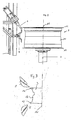
- the illustrated embodiment also includes fitting or removal tools 5 which are diagrammatically illustrated in Fig. 2 , bead breaking tools which are diagrammatically illustrated in Fig. 3 and which, when the motor vehicle wheel 1 is arranged horizontally, are caused to come into contact with side walls of the tyre 4 from below and from above in the proximity of tyre beads 12 which, when the motor vehicle tyre 1 is in the fitted condition, lie behind the two lateral rim beads 12 of the rim 3.
- fitting or removal tools 5 which are diagrammatically illustrated in Fig. 2
- bead breaking tools which are diagrammatically illustrated in Fig. 3 and which, when the motor vehicle wheel 1 is arranged horizontally, are caused to come into contact with side walls of the tyre 4 from below and from above in the proximity of tyre beads 12 which, when the motor vehicle tyre 1 is in the fitted condition, lie behind the two lateral rim beads 12 of the rim 3.
- the wheel receiving means 2 is caused to rotate by means of a rotary drive device 10 which can be in the form of an electric motor.
- the rotary drive takes place about a wheel axis 11.
- sensing devices 6 and 7 are provided at both sides of the rim 3 or in the illustrated embodiment at the top side of the rim or of the wheel 1 and at the underside of the rim or of the wheel 1 with which it is possible to implement contact-less and in particular optical sensing of the rim beads 12 at the radial outer surface (rim bed 14) of the rim 3.
- the contour of the rim bed 14 is shown in Figures 2 and 3 .
- the sensing device 6, 7 has a light source 15, e.g. a laser source, comprising a pattern generator, e.g. an optical line generator made with a cylindrical lens, which emits a planar light beam shaped in a sheet of light by the pattern generator onto the rim surface in one or more given directions and intersects the rim surface in a plurality of impingement points which forms a stripe-shaped impingement area on the wheel surface or the rim surface.
- the impingement points belong to both the impinged surface and the sheet of light. At each of these impingement points, the light beam is scattered in a plurality of light rays or beams that are reflected.
- At least a plurality of reflected light beams will be then detected by a photosensitive detector 16, e.g. an area image sensor that may be either a CCD device or preferably a CMOS device.
- a photosensitive detector 16 e.g. an area image sensor that may be either a CCD device or preferably a CMOS device.
- each of these at least a plurality of reflected light beams is concentrated by a lens 17, e.g. a single, glass, plan-convex lens that may be associated with an optical band-pass filter, into a point projected onto the focal plane of the photosensitive detector 16.
- a lens 17 e.g. a single, glass, plan-convex lens that may be associated with an optical band-pass filter
- each projected point has a position determined preferably with a sub-pixel resolution rather than the physical pixel one. That determination can be achieved by several well-known detection techniques, such as the Gaussian approximation, centroid or centre of mass algorithms, or parabolic estimator
- Relationship between the position in a three dimensional coordinate system of an impingement point, expressed in unit of length of the culinary international (SI) base unit, and the position in a two dimensional coordinate system of the corresponding projected point, expressed preferably in sub-pixel, is defined by calibration using a reverse transform.
- Calibration can be carried out either by using the so-called model-based calibration based on the geometric camera model approach or by using the direct or black-box calibration based on a polynomial interpolation such as the cubic spline interpolation.
- the spacings and thus positions of the individual impingement points sensed at the wheel (rim/tyre assembly) or the rim can then be determined in dependence on the directions of the emitted and reflected light beams.
- the geometric optical setup of the optical sensing device 6 to 8 can be designed in a way that the Scheimpflug principle is respected in order to avoid excessive defocusing at different distances, and that the background subtraction can be implemented in order to reduce the system sensitivity to ambient light.
- both the light power and the exposure time of the photosensitive detector 16 can be controlled by the system in order to achieve accurate measurements in all the environmental conditions, such as sunlight, artificial light, shiny chromed surfaces, black dusty surfaces.
- the shapes and the spatial positionings of the rim beads 12 with respect to a reference which is fixed in relation to the machine are determined in a horizontal plane.
- the outside diameters of the two rim beads 12, in particular the position of the outer peripheries of the two rim beads 12 with respect to the reference which is fixed in relation to the machine can be determined. It is also possible in that case to determine rotary angle-related heightwise and lateral run-out of the rim beads 12.
- a rotary angle sender 13 can be provided at the drive device 10 or at the wheel receiving means 2, for ascertaining the respective rotary angles.
- the corresponding rotary angle signals are sent to an evaluation arrangement 18 to which the electrical sensing signals from the sensing devices 6 and 7 are also sent.
- the sensing directions of the sensing devices 6 and 7 may be approximately parallel to the rotation axis 11 of the wheel 1.
- That evaluation arrangement 18 evaluates the sensing signals and the rotary angle signals with computer aid and, as already explained, ascertains the spatial positioning preferably of the outer peripheries and possibly also the shapes of the rim beads 12 with respect to the reference which is fixed in relation to the machine, in particular the axis of rotation of the wheel receiving means 2, which is coincident with the wheel axis 11.
- referencing is effected with respect to at least one horizontal plane that is fixed in relation to the machine, so that the spatial position of the rim beads 12 with respect to the machine frame and thus with respect to the fitting or removal tools 5 which are guided on the machine frame is determined.
- tyre beads are released from the rim beads 12 and pushed into the interior of the rim bed.
- control of the movements of the removal tools 5 is effected in dependence on the position of the rim bead peripheries and the respective rim bed profile.
- a control device 9 is connected to the evaluation arrangement 18 and to a store 19, for example in the form of a database, in which, for various types of wheels, the contours of the rim beds 14, that is to say the contours between the respective rim beads 12, are stored.
- the spatial position of the rim bed 14 which is between the two rim beads 12 and thus the position of the rim bed contour between the two rim beads 12 is also known. Accordingly, further positioning of the removal tools 5 is effected along given curved paths at a spacing from the surface of the rim bed 14.
- the control device 9 includes driver stages which are suitably designed for that purpose, for the movements of the fitting and removal tools. A respective control of the tools 5 can be performed also during the fitting of the tyre 4 on the rim 3.
- the sensing devices 6 and 7 are disposed in front of the fitting or removal tools 5, in a direction parallel to the wheel axis 11. It is then not necessary firstly to effect sensing at the rim 3 over the entire periphery of the wheel (360°), but the controlled movement of the fitting or removal tools 5 can be effected immediately after sensing of the respective rim regions when those sensed rim regions come into the region for access of the fitting or removal tools 5 in the rotary movement of the wheel.
- a third sensing device 8 can be provided for sensing the wheel rim 3, in particular for sensing the rim bed 14, and may be disposed on a support movable in a vertical direction.
- the sensing direction of that sensing device 8 is oriented substantially in a horizontal direction, wherein the overall width of the rim bed 14 between the two rim beads 12 and the outer peripheral edges of the rim beads 12 is determined so that the contour of the rim bed 14 is ascertained. That contour can also be detected in rotary angle-related relationship as at the same time the respective rotary angles are detected by means of the rotary angle sender 13 and corresponding electrical rotary angle signals are fed to the control device 9.
- the contour of the rim bed can be detected in rotary angle-related relationship in that way prior to the tyre fitting operation.
- the outer peripheral edges of the rim beads 12 and the regions, which are adjacent to the rim bed, of the rim beads 12 can also be sensed.
- the spatial positioning of the rim bed and the rim beads 12 can be determined in particular by the optical measurement of the spacing involved, for example using the previously described triangulation method.
- the fitting tools 5 can then be controlled in their movement in such a way that no contact occurs with the rim surface, in particular in the region of the rim beads 12 and in the region of the rim bed.
- the tyre profile can also be optically sensed with the sensing device 8 when the tyre 4 is mounted on the rim 3.
- the side walls of the tyre 4 can be sensed by the sensing devices 6 and 7.
- each sensing device 6, 7 and 8 can have the light source 15, in particular a laser beam source shaped in a sheet 21 of light or planar light beam by a pattern generator, e.g. an optical line generator made with a cylindrical lens, which are mounted with a photosensitive sensor 16, such as a CMOS sensor or CCD sensor, on a common carrier 20.
- a pattern generator e.g. an optical line generator made with a cylindrical lens, which are mounted with a photosensitive sensor 16, such as a CMOS sensor or CCD sensor, on a common carrier 20.
- the light source 15 can be configured to emit a single linear light beam which is swivelled about a not shown axis to be moved within a planar plane corresponding to the planar plane or light sheet 21.
- the not shown axes are arranged fixedly with respect to the machine and can form the machine-related position references for the points which are sensed on the rim 3.
- the planar light beams emitted by the respective light sources intersect the surface of the rim 3 in a plurality of impingement points and are reflected at each of that plurality of impingement points. At least a plurality of these reflected light beams is concentrated by a lens 17, e.g.
- a single, glass, plano-convex lens that may be associated with an optical band-pass filter, into a point that is projected and passed onto the sensor 16 by way of an optical receiver system.
- the projected point at the sensor 16 is proportional to the directions of the light beam which is emitted by the light source 15 and the reflected light beam and thus to the spacing of the corresponding impingement point at which the sensing light beam impinges on the rim surface.
- the spacings of the impingement points and its spatial positions with respect to the machine frame can be determined by means of the previously described triangulation method.
- the respective sensing signals of the sensors 16 are passed to the evaluation arrangement, as already described hereinbefore. Evaluation of the signals in the evaluation arrangement 18 is effected by means of an electronic computer.
- the respective rotary angle position of the rim 3 is determined by the rotary angle sender 13 which is connected to the evaluation arrangement 18.
Landscapes
- Engineering & Computer Science (AREA)
- Physics & Mathematics (AREA)
- General Physics & Mathematics (AREA)
- Mechanical Engineering (AREA)
- Computer Vision & Pattern Recognition (AREA)
- Length Measuring Devices By Optical Means (AREA)
Claims (26)
- Verfahren zum Montieren oder Demontieren eines Kraftfahrzeug Reifens (4), die Schritte beinhaltend:- Befestigen einer Felge (3) eines Kraftfahrzeugrades (Felge/Reifen-Einheit) auf einem Radaufnahmemittel (2) eines Reifenmontiergeräts;- Bestimmen der geometrischen Abmessungen des Rades (1) durch berührungsloses Erfassen, wobei- wenigstens ein ebener Lichtstrahl (21) auf mindestens eines der beiden Felgenhörner (12) des Rades (1) ausgestrahlt wird,- der auf einem streifenförmigen Auftreffbereich auf dem Rad (1) reflektierte Lichtstrahl (21), detektiert wird, und- die Richtungen der ausgestrahlten und der reflektierten Lichtstrahlen ausgewertet werden, um die Form und/oder Position des Auftreffbereichs auf dem Rad zu bestimmen; und- Führen der Bewegung eines Montier- oder Demontier-Werkzeugs (5) in Abhängigkeit von den bestimmten geometrischen Abmessungen des wenigstens einen Felgenhorns (12),
dadurch gekennzeichnet, dass- wenigstens ein ebener Lichtstrahl (21) von einer stationären Position ausgestrahlt wird, wobei- die Felgenkontur, entlang der das Montier- und Demontier-Werkzeug (5) während dem Montier- oder Demontier-Vorgang geführt wird, von dem streifenförmigen Auftreffbereich bestimmt ist, und- die Bewegung des Montier- und Demontier-Werkzeugs (5) in Abhängigkeit von der bestimmten Kontur geführt wird, ohne die Felgenoberfläche zu berühren. - Verfahren nach Anspruch 1,
dadurch gekennzeichnet, dass wenigstens ein Lichtstrahl auf das Rad oder auf die Felge gerichtet wird, das/die um eine stationäre Achse rotiert wird. - Verfahren nach Anspruch 1 oder 2,
dadurch gekennzeichnet, dass die äußere Umfangsfläche der Felge (3) mit dem ebenen Lichtstrahl (21) erfasst wird. - Verfahren nach einem der Ansprüche 1 bis 3,
dadurch gekennzeichnet, dass die Abstände der Felgenhörner (12), die von dem ebenen Lichtstrahl (21) erfasst werden, relativ zu einer stationären Referenz bestimmt werden. - Verfahren nach Anspruch 4,
dadurch gekennzeichnet, dass der Vorgang des Bestimmens des Abstandes gemäß einem Triangulationsverfahren durchgeführt wird. - Verfahren nach einem der Ansprüche 1 bis 5,
dadurch gekennzeichnet, dass jeweilige ausgestrahlte und reflektierte Lichtstrahlen, die einer Vielzahl von Auftreffpunkten auf dem streifenförmigen Auftreffbereich zugeordnet sind, detektiert werden und die Positionen der zugehörigen Auftreffpunkte bestimmt werden. - Verfahren nach Anspruch 1,
dadurch gekennzeichnet, dass die Bewegung des mindestens einen Montage- oder Demontage-Werkzeug (5) in Abhängigkeit von der erfassten Position mindestens eines der zwei Felgenhörner und in Abhängigkeit von der gespeicherten oder erfassten Kontur des Felgenhorns gesteuert wird. - Verfahren nach Anspruch 1,
dadurch gekennzeichnet, dass die Bewegung des mindestens einen Montage- oder Demontage-Werkzeugs in Abhängigkeit von der erfassten Position der äußeren Umfangskante wenigstens eines der zwei Felgenhörner (12) gesteuert wird. - Verfahren nach einem der Ansprüche 1 bis 8,
dadurch gekennzeichnet, dass der ausgestrahlte Lichtstrahl ein einzelner linearer Lichtstrahl ist, der in einer ebenen Fläche bewegt, insbesondere geschwenkt wird. - Vorrichtung zum Montieren oder Demontieren eines Kraftfahrzeugreifens (4), beinhaltend: eine drehbar gelagerte Radaufnahmeeinrichtung (2), an der das Rad (1) oder die Felge (3) fixiert werden solt, wenigstens ein Montage- oder Demontage-Werkzeug (5), eine Drehantriebsvorrichtung (10) für die Radaufnahmeeinrichtung, eine Erfassungseinrichtung (6, 7, 8) zum Erfassen der radial äußeren Kontur (12, 14), wobei die Erfassungseinrichtung (6, 7, 8) mindestens eine Lichtquelle (15) aufweist, die einen ebenen Lichtstrahl (21) von wenigstens einer vorgegebenen Position auf zumindest eines der beiden Felgenhörner (12) ausstrahlt, und einen Detektor (16), der die Richtung des Lichtstrahls detektiert, der von einem streifenförmigen Auftreffbereich auf der Reifenoberfläche reflektiert wird, eine computergestützte Auswerteanordnung (18) zum Auswerten von elektrischen Erfassungssignalen, die von der Erfassungseinrichtung (6, 7, 8) geliefert werden, die geeignet ist zum Bestimmen der Form und/oder Position der erfassten Radoberfläche, und eine Steuereinrichtung (9), die mit der Auswerteanordnung (18) verbunden ist, zum Steuern der Bewegung des wenigstens einen Montage- oder Demontage-Werkzeugs (5) während des Montage oder Demontagevorgangs in Abhängigkeit von dem erfassten Signal,
dadurch gekennzeichnet, dass die mindestens eine Lichtquelle (15) und der Detektor (16) stationär positioniert sind, dass die Auswerteanordnung (18) geeignet ist, anhand des streifenförmigen Auftreffbereichs eine Felgenkontur (12, 14) zu bestimmen, entlang der das wenigstens eine Montage- oder Demontage-Werkzeug (5) während des Montage- oder Demontagevorgangs zu führen ist, und dass die Steuereinrichtung (9) dafür konfiguriert ist, das wenigstens eine Montage- oder Demontage-Werkzeug (5) während des Montage- oder Demontagevorgangs in Abhängigkeit von der bestimmten Felgenkontur (12, 14) zu steuern, ohne die Felgenoberfläche zu berühren. - Vorrichtung nach Anspruch 10,
dadurch gekennzeichnet, dass mindestens eine Lichtquelle (15) und ein zugehöriger Detektor (16) als Erfassungseinrichtung (8) zum Erfassen der äußeren Oberfläche der Felge oder des Rades vorgesehen sind. - Vorrichtung nach Anspruch 10 oder 11,
dadurch gekennzeichnet, dass die Lichtquelle (15) und der Detektor (16) synchron um eine gemeinsame Achse (17) schwenkbar sind, um einen einzelnen Lichtstrahl in einer ebenen Fläche auszustrahlen, wobei ein elektrisches Signal proportional zu dem jeweiligen Drehwinkel der Auswerteanordnung (18) zugeführt wird. - Vorrichtung nach einem der Ansprüche 10 bis 12,
dadurch gekennzeichnet, dass die Auswerteanordnung (18) geeignet ist, die Positionen der entsprechenden Stellen, die auf der Radoberfläche oder der Felgenoberfläche abgetastet werden, anhand der Richtungen des von der Lichtquelle (15) ausgesandten Lichtstrahls und des auf der Radoberfläche oder der Felgenoberfläche reflektierten Lichtstrahls mittels Triangulation zu ermitteln. - Vorrichtung nach einem der Ansprüche 10 bis 13,
dadurch gekennzeichnet, dass das Rad oder die Felge (3) auf einer Radaufnahmeeinrichtung (2) um die Rad Achse (1) drehbar montiert wird. - Vorrichtung nach einem der Ansprüche 10 bis 14,
dadurch gekennzeichnet, dass ein Drehwinkelsensor (13) die zugehörige Drehwinkelposition des Rades oder der Felge (3) erkennt, und der Auswerteanordnung (18) ein entsprechendes elektrisches Signal zuführt. - Vorrichtung nach einem der Ansprüche 10 bis 15,
dadurch gekennzeichnet, dass die Erfassungseinrichtung (6, 7, 8) vor dem wenigstens einen Montage- oder Demontage-Werkzeug (5) in Richtung der Drehung der Radaufnahmeeinrichtung (2) angeordnet ist. - Vorrichtung nach einem der Ansprüche 10 bis 16,
dadurch gekennzeichnet, dass die Erfassungsrichtung der Erfassungseinrichtungen (6, 7) annähernd parallel zu der Rotationsachse (11) des Rades oder der Felge ist. - Vorrichtung nach einem der Ansprüche 10 bis 17,
dadurch gekennzeichnet, dass die räumlichen Positionen der entsprechend erfassten Punkte auf dem Rad (1) oder der Felge (3) in Bezug auf den Maschinenrahmen der Vorrichtung und insbesondere in Bezug auf das jeweilige Montage- oder Demontage-Werkzeug (5) bestimmt werden. - Vorrichtung nach einem der Ansprüche 10 bis 18,
dadurch gekennzeichnet, dass die Auswerteanordnung (18) dafür ausgelegt ist, die jeweilige räumliche Position der Felgenhörner (12) und insbesondere die äußeren Umfangskanten der Felgenhörner (12) zu bestimmen. - Vorrichtung nach einem der Ansprüche 10 bis 19,
dadurch gekennzeichnet, dass die Auswerteanordnung (18) geeignet ist, die räumliche Position des Felgenbetts (14) zu bestimmen, das zwischen den Felgenhörnern (12) liegt. - Vorrichtung nach einem der Ansprüche 10 bis 20,
dadurch gekennzeichnet, dass für unterschiedliche Radtypen die Konturen der Felgenbetten (14) in einem Speicher (19) der Steuereinrichtung (9) oder in einem mit der Steuereinrichtung verbundenen Speicher gespeichert werden. - Vorrichtung nach einem der Ansprüche 10 bis 21,
dadurch gekennzeichnet, dass die Konturen der Felgenhörner (12) zusätzlich in dem Speicher (19) gespeichert werden. - Vorrichtung nach einem der Ansprüche 10 bis 22,
dadurch gekennzeichnet, dass für unterschiedliche Radtypen die Eigenschaften der Räder in einem Speicher der Steuereinrichtung (9) gespeichert werden. - Vorrichtung nach einem der Ansprüche 10 bis 23,
dadurch gekennzeichnet, dass die Lichtquelle (15) ein Laser ist. - Vorrichtung nach einem der Ansprüche 10 bis 24,
dadurch gekennzeichnet, dass der Detektor (16) eine Komplementär-Metall-Oxid-Halbleiter-(CMOS)-Einrichtung oder eine ladungsgekoppelten Einrichtung (CCD) aufweist. - Verwendung eines Verfahrens nach einem der Ansprüche 1 bis 9 oder einer Vorrichtung nach einem der Ansprüche 10 bis 25 zum Bestimmen wenigstens eines der Parameter: Reifenschlag, Abnutzung der Lauffläche des Reifens, Reifenkonizität, Reifenschäden auf der Lauffläche und/oder an den Seitenwänden, Felgenschäden auf der Außenseite und/oder der Innenseite der Felge und Felgenschultergeometrie der Felge.
Priority Applications (5)
| Application Number | Priority Date | Filing Date | Title |
|---|---|---|---|
| ES07010263T ES2369002T3 (es) | 2007-05-23 | 2007-05-23 | Procedimiento y aparato para determinar la dimensión geométrica de una rueda de vehículo que comprende sensores ópticos. |
| EP11159450.3A EP2332749B1 (de) | 2007-05-23 | 2007-05-23 | Verfahren und Vorrichtung zum Bestimmen der geometrischen Abmessungen eines Fahrzeugrades mittels optischer Sensoren |
| EP07010263A EP1995083B1 (de) | 2007-05-23 | 2007-05-23 | Verfahren und Vorrichtung zum Bestimmen der geometrischen Abmessungen eines Fahrzeugrades mittels optischer Sensoren |
| CN2008100999388A CN101311669B (zh) | 2007-05-23 | 2008-05-22 | 安装或拆卸汽车轮胎的方法和设备 |
| US12/126,368 US7768632B2 (en) | 2007-05-23 | 2008-05-23 | Method of and apparatus for determining geometrical dimensions of a vehicle wheel |
Applications Claiming Priority (1)
| Application Number | Priority Date | Filing Date | Title |
|---|---|---|---|
| EP07010263A EP1995083B1 (de) | 2007-05-23 | 2007-05-23 | Verfahren und Vorrichtung zum Bestimmen der geometrischen Abmessungen eines Fahrzeugrades mittels optischer Sensoren |
Related Child Applications (2)
| Application Number | Title | Priority Date | Filing Date |
|---|---|---|---|
| EP11159450.3A Division EP2332749B1 (de) | 2007-05-23 | 2007-05-23 | Verfahren und Vorrichtung zum Bestimmen der geometrischen Abmessungen eines Fahrzeugrades mittels optischer Sensoren |
| EP11159450.3 Division-Into | 2011-03-23 |
Publications (2)
| Publication Number | Publication Date |
|---|---|
| EP1995083A1 EP1995083A1 (de) | 2008-11-26 |
| EP1995083B1 true EP1995083B1 (de) | 2011-08-31 |
Family
ID=38542972
Family Applications (2)
| Application Number | Title | Priority Date | Filing Date |
|---|---|---|---|
| EP07010263A Active EP1995083B1 (de) | 2007-05-23 | 2007-05-23 | Verfahren und Vorrichtung zum Bestimmen der geometrischen Abmessungen eines Fahrzeugrades mittels optischer Sensoren |
| EP11159450.3A Active EP2332749B1 (de) | 2007-05-23 | 2007-05-23 | Verfahren und Vorrichtung zum Bestimmen der geometrischen Abmessungen eines Fahrzeugrades mittels optischer Sensoren |
Family Applications After (1)
| Application Number | Title | Priority Date | Filing Date |
|---|---|---|---|
| EP11159450.3A Active EP2332749B1 (de) | 2007-05-23 | 2007-05-23 | Verfahren und Vorrichtung zum Bestimmen der geometrischen Abmessungen eines Fahrzeugrades mittels optischer Sensoren |
Country Status (4)
| Country | Link |
|---|---|
| US (1) | US7768632B2 (de) |
| EP (2) | EP1995083B1 (de) |
| CN (1) | CN101311669B (de) |
| ES (1) | ES2369002T3 (de) |
Cited By (1)
| Publication number | Priority date | Publication date | Assignee | Title |
|---|---|---|---|---|
| CN110023068A (zh) * | 2016-11-30 | 2019-07-16 | 倍耐力轮胎股份公司 | 用于控制轮胎生产的固化设备的方法、固化线、处理单元和相关电子单元 |
Families Citing this family (46)
| Publication number | Priority date | Publication date | Assignee | Title |
|---|---|---|---|---|
| JP5043013B2 (ja) * | 2006-07-31 | 2012-10-10 | Hoya株式会社 | レンズ形状測定装置及び方法、並びに眼鏡レンズの製造方法 |
| ES2329707T3 (es) * | 2006-11-28 | 2009-11-30 | Snap-On Equipment Srl A Unico Socio | Procedimiento y aparato para determinar las dimensiones geometricas de una llanta de rueda, en particular al montar y/o desmontar un neumatico de vehiculo a motor. |
| ES2356039T3 (es) * | 2008-04-17 | 2011-04-04 | Snap-On Equipment Srl A Unico Socio | Procedimiento y aparato para montar y desmontar un neumático de vehículo a motor. |
| IT1391808B1 (it) * | 2008-10-31 | 2012-01-27 | Sicam Srl | Macchina smontagomme per il montaggio e lo smontaggio di ruote di veicoli |
| KR101108250B1 (ko) * | 2009-11-10 | 2012-02-09 | 한국타이어 주식회사 | 타이어 마모 측정 장치 |
| ATE551212T1 (de) | 2010-01-20 | 2012-04-15 | Snap On Equip Srl Unico Socio | Verfahren zur befestigung eines reifen an einer felge zum erhalten eines fahrzeugrades und verfahren zur demontage eines reifens von einer felge sowie vorrichtung dafür |
| EP2353890A1 (de) * | 2010-01-29 | 2011-08-10 | Snap-on Equipment Srl a unico socio | Vorrichtung und Verfahren zur Bestimmung geometrischer Abmessungen eines Reifens mittels optischer Sensoren |
| EP2361791B1 (de) | 2010-02-17 | 2013-06-05 | Snap-on Equipment Srl a unico socio | Démonte-pneu et procédé de mesure des variations de force agissant entre la surface périphérique d'un ensemble roue/pneu et d'un roulement |
| DE102010037079A1 (de) * | 2010-08-19 | 2012-02-23 | Schenck Rotec Gmbh | Verfahren und Vorrichtung zur Kontrolle des Reifensitzes an Fahrzeugrädern |
| CN103234474B (zh) * | 2012-11-19 | 2015-09-30 | 北京东方鼎鑫科技有限公司 | 一种汽车铝合金轮毂毛坯在线变形测量方法及测量装置 |
| EP2741066B1 (de) | 2012-12-06 | 2019-04-17 | Snap-on Equipment Srl a unico socio | Verfahren zur Bestimmung von Daten in Bezug auf den Drehwinkel eines Fahrzeugrads |
| WO2014124349A1 (en) * | 2013-02-11 | 2014-08-14 | Pneumacore, Inc. | Detecting wheel rim cracks |
| EP2781377A1 (de) | 2013-03-21 | 2014-09-24 | Snap-on Equipment Srl a unico socio | Reifenmontage- und -demontagevorrichtung mit Ladegurtvorrichtung |
| JP5946424B2 (ja) * | 2013-05-01 | 2016-07-06 | 株式会社神戸製鋼所 | タイヤ試験機 |
| US10013754B2 (en) * | 2013-08-09 | 2018-07-03 | Hunter Engineering Company | Method and apparatus for utilizing wheel profile data during wheel assembly service procedures |
| DE102013216566A1 (de) | 2013-08-21 | 2015-02-26 | Fraunhofer-Gesellschaft zur Förderung der angewandten Forschung e.V. | Vorrichtung und verfahren zur erfassung einer zumindest teilweise spiegelnden oberfläche |
| US9662945B2 (en) * | 2013-10-04 | 2017-05-30 | Hunter Engineering Company | Robotic tire changer user interaction procedures for safety and convenience |
| CN103900490A (zh) * | 2014-03-24 | 2014-07-02 | 青岛泰凯英轮胎有限公司 | 一种轮胎不圆度检测设备及方法 |
| JP6159294B2 (ja) * | 2014-06-02 | 2017-07-05 | 住友ゴム工業株式会社 | タイヤのトレッド形状測定方法、及びそれに用いるトレッド形状測定装置 |
| ES2940781T3 (es) * | 2014-09-15 | 2023-05-11 | Nexion Spa | Máquina de mantenimiento de rueda y método para realizar la evaluación diagnóstica de una rueda de vehículo |
| EP3054278B1 (de) * | 2015-02-09 | 2018-05-09 | Snap-on Equipment S.r.l. | Vorrichtung zum anheben von mindestens einem kraftfahrzeugrad oder reifen mit detektor des verschleissgrades von letzterem |
| WO2017103809A1 (en) * | 2015-12-16 | 2017-06-22 | Pirelli Tyre S.P.A. | Apparatus and method for the analysis of tyres |
| CN105783769A (zh) * | 2015-12-30 | 2016-07-20 | 南京理工大学 | 基于线激光扫描的齿轮三维轮廓测量系统及方法 |
| PL3244161T3 (pl) * | 2016-05-10 | 2019-07-31 | MW Lublin SP. z o.o. | Bezdotykowy system pomiarowy dla kół pojazdów drogowych |
| CN106247937B (zh) * | 2016-08-29 | 2018-10-12 | 保定市立中车轮制造有限公司 | 一种毛坯墩检测系统及其检测方法 |
| CN106403813A (zh) * | 2016-08-29 | 2017-02-15 | 天津立中车轮有限公司 | 一种车轮全面检测装置 |
| CN106500620A (zh) * | 2016-10-31 | 2017-03-15 | 吉林大学 | 基于主动视觉的汽车轮胎形貌检测仪 |
| CN108007386B (zh) * | 2016-11-02 | 2021-04-20 | 光宝电子(广州)有限公司 | 基于结构光的三维扫描方法及其装置与系统 |
| CN106352796A (zh) * | 2016-11-04 | 2017-01-25 | 无锡市计量检定测试中心 | 激光盘轴类零件测量仪 |
| CN110678726B (zh) | 2017-06-12 | 2022-02-25 | 倍耐力轮胎股份公司 | 用于检查轮胎的方法 |
| IT201700065506A1 (it) * | 2017-06-13 | 2018-12-13 | Snap On Equipment S R L A Unico Socio | Metodo ed apparato perfezionati per montare o smontare pneumatici su cerchioni |
| CN108168908B (zh) * | 2018-01-15 | 2024-04-09 | 浙江今跃机械科技开发有限公司 | 轮毂凸峰检测系统 |
| US11994386B2 (en) | 2018-05-01 | 2024-05-28 | Red Tuna | Optical vehicle diagnostic system |
| CN109724531B (zh) * | 2018-10-18 | 2021-05-28 | 苏州光图智能科技有限公司 | 360°轮廓测量方法 |
| CN111959195A (zh) * | 2020-07-07 | 2020-11-20 | 东风汽车底盘系统有限公司 | 车轮一次谐波径向跳动低点对轮胎rfv高点装配方法 |
| CN112577432A (zh) * | 2020-10-16 | 2021-03-30 | 深圳精匠云创科技有限公司 | 轮毂尺寸自动测量方法及测量装置 |
| CN112378347B (zh) * | 2020-11-05 | 2022-03-08 | 中国科学院沈阳自动化研究所 | 一种大型轴承套圈圆柱度测量仪 |
| CN112284256B (zh) * | 2020-11-17 | 2022-06-10 | 深圳市道通科技股份有限公司 | 一种工件平面磨损的测量方法和系统 |
| CN113390341B (zh) * | 2021-06-18 | 2023-03-14 | 赛轮(沈阳)轮胎有限公司 | 一种胎胚定型后胎体反包自动检测方法与系统 |
| CN113390356B (zh) * | 2021-07-07 | 2025-03-25 | 迪迈自动化(青岛)有限公司 | 一种全自动、多参数测量设备及其使用方法 |
| IT202100018722A1 (it) | 2021-07-16 | 2023-01-16 | Snap On Equip Srl Unico Socio | Apparato smontagomme |
| DE102022127300A1 (de) | 2022-10-18 | 2024-04-18 | ARS Automotive Robotic Solutions GmbH | Werkzeug, System und Verfahren zum automatisierten Positionieren eines Aufpumpwerkzeuges auf einem Reifenventil einer Felge |
| CN115962736A (zh) * | 2022-12-29 | 2023-04-14 | 软控股份有限公司 | 一种轮胎偏心度自动测量装置及测量方法 |
| TWI870171B (zh) * | 2023-12-20 | 2025-01-11 | 財團法人工業技術研究院 | 輪圈粗胚檢測裝置 |
| AT528024B1 (de) * | 2024-06-17 | 2025-09-15 | Enigmasoft Gmbh | Vorrichtung zum Vermessen von Rotationsprüfobjekten |
| CN118500296B (zh) * | 2024-07-17 | 2024-09-13 | 常州医疗器材总厂股份有限公司 | 基于批量检测的输液器硬座锥度检测装置及方法 |
Family Cites Families (13)
| Publication number | Priority date | Publication date | Assignee | Title |
|---|---|---|---|---|
| US3877505A (en) | 1973-01-30 | 1975-04-15 | David W Besuden | Upper bead breaker mechanism |
| DE2529343C3 (de) | 1975-07-01 | 1981-07-09 | Gebr. Hofmann Gmbh & Co Kg Maschinenfabrik, 6100 Darmstadt | Vorrichtung zum Montieren und Demontieren von Kraftfahrzeugreifen, insbesondere für Lastkraftwagen |
| US5054918A (en) | 1990-02-02 | 1991-10-08 | Fmc Corporation | Light scanning system for measurement of orientation and physical features of a workpiece |
| JP2001004344A (ja) * | 1999-06-25 | 2001-01-12 | Anzen Motor Car Co Ltd | 車両ホイールのアライメント測定装置 |
| DE10035118B4 (de) * | 2000-07-19 | 2009-10-01 | Snap-On Equipment Gmbh | Verfahren und Vorrichtung zum optischen Abtasten eines Fahrzeugrades |
| US7355687B2 (en) | 2003-02-20 | 2008-04-08 | Hunter Engineering Company | Method and apparatus for vehicle service system with imaging components |
| ITVR20030062A1 (it) * | 2003-05-19 | 2004-11-20 | Butler Eng & Marketing | Apparecchiatura di manutenzione di una ruota gommata |
| DE10335829A1 (de) * | 2003-08-05 | 2005-03-10 | Siemens Ag | Verfahren zur Bestimmung der Achsgeometrie und Sensor zu dessen Durchführung |
| DE50310901D1 (de) * | 2003-09-04 | 2009-01-22 | Snap On Equipment S R L A Unic | Verfahren und Vorrichtung zum optischen Abtasten eines Fahrzeugrades |
| ES2247467T3 (es) * | 2003-09-04 | 2006-03-01 | Snap-On Equipment Srl A Unico Socio. | Exploracion optica por puntos del estado de un neumatico de una rueda de un vehiculo (con dispositivo de equilibrado de rueda). |
| ITVR20040055A1 (it) * | 2004-04-09 | 2004-07-09 | Butler Eng & Marketing | Tastatore automatico per macchine monta-smontagomme |
| US7221441B2 (en) * | 2004-08-06 | 2007-05-22 | Hunter Engineering Company | Method for measuring optically reflective vehicle wheel surfaces |
| ITMO20050226A1 (it) * | 2005-09-09 | 2007-03-10 | Sicam Srl | Macchina per l'equilibratura di ruote di veicoli |
-
2007
- 2007-05-23 ES ES07010263T patent/ES2369002T3/es active Active
- 2007-05-23 EP EP07010263A patent/EP1995083B1/de active Active
- 2007-05-23 EP EP11159450.3A patent/EP2332749B1/de active Active
-
2008
- 2008-05-22 CN CN2008100999388A patent/CN101311669B/zh active Active
- 2008-05-23 US US12/126,368 patent/US7768632B2/en active Active
Cited By (2)
| Publication number | Priority date | Publication date | Assignee | Title |
|---|---|---|---|---|
| CN110023068A (zh) * | 2016-11-30 | 2019-07-16 | 倍耐力轮胎股份公司 | 用于控制轮胎生产的固化设备的方法、固化线、处理单元和相关电子单元 |
| US11007734B2 (en) | 2016-11-30 | 2021-05-18 | Pirelli Tyre S.P.A. | Method, curing line, processing unit and associated electronic unit for controlling curing apparatuses for tyre production |
Also Published As
| Publication number | Publication date |
|---|---|
| CN101311669A (zh) | 2008-11-26 |
| US7768632B2 (en) | 2010-08-03 |
| EP2332749A1 (de) | 2011-06-15 |
| ES2369002T3 (es) | 2011-11-24 |
| US20080297777A1 (en) | 2008-12-04 |
| EP1995083A1 (de) | 2008-11-26 |
| EP2332749B1 (de) | 2017-11-29 |
| CN101311669B (zh) | 2011-10-12 |
Similar Documents
| Publication | Publication Date | Title |
|---|---|---|
| EP1995083B1 (de) | Verfahren und Vorrichtung zum Bestimmen der geometrischen Abmessungen eines Fahrzeugrades mittels optischer Sensoren | |
| US7715024B2 (en) | Method of and apparatus for determining geometrical dimensions of a wheel rim, in particular when fitting and/or removing a motor vehicle tyre | |
| US7738120B2 (en) | Method and apparatus for determining geometrical dimensions of a vehicle wheel | |
| US20110188052A1 (en) | Apparatus and method of determining geometrical dimensions of a tyre by contact-less sensing | |
| US8342222B2 (en) | Method for mounting a tyre on a rim to form a motor vehicle wheel and for demounting a tyre from a rim and apparatus therefore | |
| CN112352146B (zh) | 用于传感器校准的车辆对准 | |
| US8342223B2 (en) | Method of and apparatus for fitting or removing a motor vehicle tyre | |
| EP2038606B1 (de) | Vorrichtung und verfahren zum bestimmen der ausrichtung eines objekts, wie z.b. die fahrzeugreifenausrichtung | |
| TW493060B (en) | Method and apparatus for measuring vehicle wheel scrub radius | |
| EP3054278B1 (de) | Vorrichtung zum anheben von mindestens einem kraftfahrzeugrad oder reifen mit detektor des verschleissgrades von letzterem | |
| CN105937888B (zh) | 检测轮胎的偏心率的方法以及设备 | |
| US7746456B2 (en) | Apparatus for contactless 3D wheel alignment, system and method therefor | |
| HK1158147A (en) | Apparatus and method of determing geometrical dimensions of a tyre with optical sensors | |
| JPH0434305A (ja) | 法線方向検出装置 | |
| HK1158145B (en) | Method for mounting a tyre on a rim to form a motor vehicle wheel and for demounting a tyre from a rim and apparatus therefore |
Legal Events
| Date | Code | Title | Description |
|---|---|---|---|
| PUAI | Public reference made under article 153(3) epc to a published international application that has entered the european phase |
Free format text: ORIGINAL CODE: 0009012 |
|
| AK | Designated contracting states |
Kind code of ref document: A1 Designated state(s): AT BE BG CH CY CZ DE DK EE ES FI FR GB GR HU IE IS IT LI LT LU LV MC MT NL PL PT RO SE SI SK TR |
|
| AX | Request for extension of the european patent |
Extension state: AL BA HR MK RS |
|
| 17P | Request for examination filed |
Effective date: 20090127 |
|
| 17Q | First examination report despatched |
Effective date: 20090313 |
|
| AKX | Designation fees paid |
Designated state(s): DE ES FR GB IT |
|
| GRAP | Despatch of communication of intention to grant a patent |
Free format text: ORIGINAL CODE: EPIDOSNIGR1 |
|
| GRAS | Grant fee paid |
Free format text: ORIGINAL CODE: EPIDOSNIGR3 |
|
| GRAA | (expected) grant |
Free format text: ORIGINAL CODE: 0009210 |
|
| AK | Designated contracting states |
Kind code of ref document: B1 Designated state(s): DE ES FR GB IT |
|
| REG | Reference to a national code |
Ref country code: GB Ref legal event code: FG4D |
|
| REG | Reference to a national code |
Ref country code: DE Ref legal event code: R096 Ref document number: 602007016668 Country of ref document: DE Effective date: 20111124 Ref country code: ES Ref legal event code: FG2A Ref document number: 2369002 Country of ref document: ES Kind code of ref document: T3 Effective date: 20111124 |
|
| PLBE | No opposition filed within time limit |
Free format text: ORIGINAL CODE: 0009261 |
|
| STAA | Information on the status of an ep patent application or granted ep patent |
Free format text: STATUS: NO OPPOSITION FILED WITHIN TIME LIMIT |
|
| 26N | No opposition filed |
Effective date: 20120601 |
|
| REG | Reference to a national code |
Ref country code: DE Ref legal event code: R097 Ref document number: 602007016668 Country of ref document: DE Effective date: 20120601 |
|
| REG | Reference to a national code |
Ref country code: FR Ref legal event code: PLFP Year of fee payment: 10 |
|
| REG | Reference to a national code |
Ref country code: FR Ref legal event code: PLFP Year of fee payment: 11 |
|
| REG | Reference to a national code |
Ref country code: FR Ref legal event code: PLFP Year of fee payment: 12 |
|
| PGFP | Annual fee paid to national office [announced via postgrant information from national office to epo] |
Ref country code: IE Payment date: 20190520 Year of fee payment: 16 |
|
| PGFP | Annual fee paid to national office [announced via postgrant information from national office to epo] |
Ref country code: GB Payment date: 20190523 Year of fee payment: 13 |
|
| GBPC | Gb: european patent ceased through non-payment of renewal fee |
Effective date: 20200523 |
|
| PG25 | Lapsed in a contracting state [announced via postgrant information from national office to epo] |
Ref country code: GB Free format text: LAPSE BECAUSE OF NON-PAYMENT OF DUE FEES Effective date: 20200523 |
|
| REG | Reference to a national code |
Ref country code: ES Ref legal event code: FD2A Effective date: 20211004 |
|
| PG25 | Lapsed in a contracting state [announced via postgrant information from national office to epo] |
Ref country code: ES Free format text: LAPSE BECAUSE OF NON-PAYMENT OF DUE FEES Effective date: 20200524 |
|
| P01 | Opt-out of the competence of the unified patent court (upc) registered |
Effective date: 20230517 |
|
| PGFP | Annual fee paid to national office [announced via postgrant information from national office to epo] |
Ref country code: DE Payment date: 20250529 Year of fee payment: 19 |
|
| PGFP | Annual fee paid to national office [announced via postgrant information from national office to epo] |
Ref country code: IT Payment date: 20250521 Year of fee payment: 19 |
|
| PGFP | Annual fee paid to national office [announced via postgrant information from national office to epo] |
Ref country code: FR Payment date: 20250526 Year of fee payment: 19 |