EP1994975A1 - Un ensemble de plusieurs sécheurs pour un gaz - Google Patents
Un ensemble de plusieurs sécheurs pour un gaz Download PDFInfo
- Publication number
- EP1994975A1 EP1994975A1 EP08014682A EP08014682A EP1994975A1 EP 1994975 A1 EP1994975 A1 EP 1994975A1 EP 08014682 A EP08014682 A EP 08014682A EP 08014682 A EP08014682 A EP 08014682A EP 1994975 A1 EP1994975 A1 EP 1994975A1
- Authority
- EP
- European Patent Office
- Prior art keywords
- dryer
- adsorption
- dryers
- air
- compressed air
- Prior art date
- Legal status (The legal status is an assumption and is not a legal conclusion. Google has not performed a legal analysis and makes no representation as to the accuracy of the status listed.)
- Withdrawn
Links
Images

Classifications
-
- B—PERFORMING OPERATIONS; TRANSPORTING
- B01—PHYSICAL OR CHEMICAL PROCESSES OR APPARATUS IN GENERAL
- B01D—SEPARATION
- B01D53/00—Separation of gases or vapours; Recovering vapours of volatile solvents from gases; Chemical or biological purification of waste gases, e.g. engine exhaust gases, smoke, fumes, flue gases, aerosols
- B01D53/26—Drying gases or vapours
- B01D53/261—Drying gases or vapours by adsorption
-
- B—PERFORMING OPERATIONS; TRANSPORTING
- B01—PHYSICAL OR CHEMICAL PROCESSES OR APPARATUS IN GENERAL
- B01D—SEPARATION
- B01D53/00—Separation of gases or vapours; Recovering vapours of volatile solvents from gases; Chemical or biological purification of waste gases, e.g. engine exhaust gases, smoke, fumes, flue gases, aerosols
- B01D53/26—Drying gases or vapours
- B01D53/265—Drying gases or vapours by refrigeration (condensation)
Definitions
- the invention relates to a total of several dryers for a gas, in particular for compressed air, wherein each dryer comprises a refrigeration dryer and a combined with it, integrable in the cycle of the refrigerant dryer adsorption.
- Such dryers are from the German utility model DE 92 01 713 U1 (Hankison GmbH, 1992).
- Certain production processes require reliable, high-quality compressed air (eg instrument air, air for pneumatic controls and process engineering, conveying air for the transport of powdered materials in chemistry, pharmacy, food technology, etc.).
- the air should be technically oil-free and also very dry.
- Pressure dew points from below 0 ° C down to -40 ° C i. d. R. desired. If the working medium air with pressure dew points above +3 ° C is now conveyed through a widely branched pipeline network or in places also through open-air piping systems, disturbances due to frozen condensate can not be ruled out and are particularly common in the winter months. Plant downtimes or drops in quality within the production, but in any case significant consequential costs are the unpleasant and expensive effects that must be avoided.
- the two essential units namely the refrigerant dryer and the adsorption dryer are precisely matched to enable the economic cooperation of the two units.
- One connection of this adsorption dryer to another refrigeration dryer, z. B. with a different performance is not possible.
- the invention has for its object to make the principle of the combined adsorption refrigeration dryer considerably more versatile and thus for any dryer combinations a significant energy savings and associated with achieving a significant CO 2 reduction.
- the adsorption dryer only requires the operating pressure and the volume flow as a reference variable and does not have to be adapted to the ambient conditions of its respective location.
- the purpose of the refrigeration dryer is to provide the required +3 ° C dew point at 100% saturation. In order to cope with the world-wide very different conditions for ambient temperatures and compressed air inlet temperatures, different refrigeration dryers with different capacities are necessary.
- the adsorption dryer can be switched on and that the dryer has a control unit which switches on the adsorption dryer when the temperature falls below a predetermined outside temperature.
- Adsorption dryers are used when the compressed air system is exposed to temperatures below freezing or when a particularly low pressure dew point is required for special applications.
- the air is passed through a container 7 filled with desiccant (activated alumina), where the water vapor accumulates on the surface of the desiccant.
- desiccant activated alumina
- the dryers have two adsorption tanks 7.
- the compressed air supply is switched so that one container always dries, while the other container, which is not flowed through by compressed air, regenerates the desiccant.
- the regeneration of the desiccant takes place by means of a blower 9 and a mostly electrically operated heater 10.
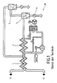
- FIG. 3 A flow diagram of the arrangement according to the invention is shown in FIG. 3 shown.
- the moist air enters the refrigeration dryer 20 at the inlet 11 at a pressure of 7 bar and at a temperature of around +35 ° C.
- the air is cooled to about +3 ° C. This condenses the water vapor. It can be separated in the integrated separating filter 4.
- the subsequent filtration of the air in the fine oil filter 6 ensures the absence of oil in the compressed air.
- the pressure dew point (DTP) is now +3 ° C.
- the temperature and the dew point of the air are congruent. Now the medium is saturated with moisture, ie the relative humidity of the air is 100%. The ideal state for the adsorbent used is thus achieved.
- the air enters the adsorption dryer 21 at an almost constant temperature.
- adsorption in the desiccant containers 7 drying on a DTP, depending on the design of -25 ° C to -40 ° C instead.
- the air through a particulate filter 8, which retains the desiccant abrasion, in turn fed to the refrigerant dryer 20 integrated air / air heat exchanger 1, which they then with a processing temperature, for example, from about +27 ° C, and with a DTP of -. 40 ° C and a pressure of 6.6 bar at the outlet 12 leaves.
- An outside temperature controlled compressed air bypass 15 allows the adsorption dryer 21 to circumnavigate as needed in the summer and only to put into operation during the winter months. As already mentioned, the far more favorable operating costs justify the slightly higher investment costs of the integrated refrigeration dryer.
- the refrigeration dryer which removes the main water load (85%) from the compressed air network is used up to a pressure dew point of +3 ° C.
- the energy and CO 2 savings effect is further enhanced with the outside temperature controlled compressed air bypass, with which the adsorber and the associated energy costs can be switched off completely in the summer.
Landscapes
- Chemical & Material Sciences (AREA)
- Engineering & Computer Science (AREA)
- Analytical Chemistry (AREA)
- General Chemical & Material Sciences (AREA)
- Oil, Petroleum & Natural Gas (AREA)
- Chemical Kinetics & Catalysis (AREA)
- Physics & Mathematics (AREA)
- Thermal Sciences (AREA)
- Drying Of Gases (AREA)
Applications Claiming Priority (2)
| Application Number | Priority Date | Filing Date | Title |
|---|---|---|---|
| DE202008005228 | 2008-04-15 | ||
| DE202008006346U DE202008006346U1 (de) | 2008-04-15 | 2008-05-08 | Gesamtheit von mehreren Trocknern für ein Gas |
Publications (1)
| Publication Number | Publication Date |
|---|---|
| EP1994975A1 true EP1994975A1 (fr) | 2008-11-26 |
Family
ID=39768755
Family Applications (1)
| Application Number | Title | Priority Date | Filing Date |
|---|---|---|---|
| EP08014682A Withdrawn EP1994975A1 (fr) | 2008-04-15 | 2008-08-19 | Un ensemble de plusieurs sécheurs pour un gaz |
Country Status (1)
| Country | Link |
|---|---|
| EP (1) | EP1994975A1 (fr) |
Cited By (2)
| Publication number | Priority date | Publication date | Assignee | Title |
|---|---|---|---|---|
| ITPN20090039A1 (it) * | 2009-06-19 | 2010-12-20 | Parker Hiross S P A | "procedimento e apparecchio per l'essicazione di gas compresso" |
| FR3011915A1 (fr) * | 2013-10-10 | 2015-04-17 | Air Liquide | Procede et appareil de separation d'air par distillation cryogenique pour la production d'azote gazeux |
Citations (4)
| Publication number | Priority date | Publication date | Assignee | Title |
|---|---|---|---|---|
| DE1240821B (de) * | 1963-07-27 | 1967-05-24 | Chlorator G M B H | Verfahren und Vorrichtung zur kontinuierlichen Trocknung von Gasstroemen |
| DE9201713U1 (de) | 1992-02-12 | 1992-06-17 | Hankison GmbH, 4130 Moers | Trocknerkombination von Kälte- und warmregeneriertem Adsorptionstrockner zur wirtschaftlichen Aufbereitung von Druckluft bei tiefen Taupunkten |
| DE10355927A1 (de) * | 2003-11-29 | 2005-06-30 | Tepcon Engineering Gesellschaft Mbh | Verfahren mit Kombinationstrockner zur Aufbereitung von Druckluft und Gasen |
| WO2006081635A1 (fr) * | 2005-02-01 | 2006-08-10 | Atlas Copco Airpower, Naamloze Vennootschap | Dispositif de dessiccation du gaz |
-
2008
- 2008-08-19 EP EP08014682A patent/EP1994975A1/fr not_active Withdrawn
Patent Citations (4)
| Publication number | Priority date | Publication date | Assignee | Title |
|---|---|---|---|---|
| DE1240821B (de) * | 1963-07-27 | 1967-05-24 | Chlorator G M B H | Verfahren und Vorrichtung zur kontinuierlichen Trocknung von Gasstroemen |
| DE9201713U1 (de) | 1992-02-12 | 1992-06-17 | Hankison GmbH, 4130 Moers | Trocknerkombination von Kälte- und warmregeneriertem Adsorptionstrockner zur wirtschaftlichen Aufbereitung von Druckluft bei tiefen Taupunkten |
| DE10355927A1 (de) * | 2003-11-29 | 2005-06-30 | Tepcon Engineering Gesellschaft Mbh | Verfahren mit Kombinationstrockner zur Aufbereitung von Druckluft und Gasen |
| WO2006081635A1 (fr) * | 2005-02-01 | 2006-08-10 | Atlas Copco Airpower, Naamloze Vennootschap | Dispositif de dessiccation du gaz |
Cited By (4)
| Publication number | Priority date | Publication date | Assignee | Title |
|---|---|---|---|---|
| ITPN20090039A1 (it) * | 2009-06-19 | 2010-12-20 | Parker Hiross S P A | "procedimento e apparecchio per l'essicazione di gas compresso" |
| EP2263778A1 (fr) | 2009-06-19 | 2010-12-22 | Parker Hiross S.p.A. | Procédé et appareil pour sécher des gaz comprimés |
| FR3011915A1 (fr) * | 2013-10-10 | 2015-04-17 | Air Liquide | Procede et appareil de separation d'air par distillation cryogenique pour la production d'azote gazeux |
| WO2015052444A3 (fr) * | 2013-10-10 | 2016-01-14 | L'air Liquide, Societe Anonyme Pour L'etude Et L'exploitation Des Procedes Georges Claude | Procédé et appareil de séparation d'air par distillation cryogénique pour la production d'azote gazeux |
Similar Documents
| Publication | Publication Date | Title |
|---|---|---|
| EP1926400B1 (fr) | Procede et dispositif pour creer une atmosphere conditionnee | |
| DE102014108977A1 (de) | Vorrichtung und Verfahren zum Trocknen von Gasen | |
| DE2702701A1 (de) | Verfahren zur wassergewinnung aus feuchter luft und anlage zur durchfuehrung des verfahrens | |
| EP1821042A2 (fr) | Dispositif de déshumidification | |
| DE3814175A1 (de) | Verfahren und anordnung zum regenerieren von adsorptionsmaterial | |
| DE10028030A1 (de) | Sorptionsvorrichtung zum Heizen und Kühlen von Gasströmen | |
| DE102006054875A1 (de) | Konditioniervorrichtung für den Zuluftstrom einer Trocknungskabine einer Lackieranlage und Verfahren zur Konditionierung des Zuluftstroms | |
| DE102006022293A1 (de) | Trocknung von Druckluft unter Nutzung der Verdichterwärme mit geschlossenem Regenerationskreislauf | |
| DE102012112040B4 (de) | Vorrichtung und Verfahren zum Trocknen von Gasen | |
| DE102006023161B4 (de) | Trocknung von Druckluft unter Nutzung externer Wärme mit geschlossenem Regenerationskreislauf | |
| DE602004005472T2 (de) | Verfahren zum trennen von gasen von einem gasgemisch und vorrichtung zur anwendung solch eines verfahrens | |
| EP1994975A1 (fr) | Un ensemble de plusieurs sécheurs pour un gaz | |
| EP2162687A1 (fr) | Machine frigorifique comprenant différentes matières de sorption | |
| CN207438936U (zh) | 一种两路旁通三级自复叠制冷系统 | |
| EP0539816A1 (fr) | Dispositif pour le dégivrage de séchoirs à réfrigération à température inférieure à 0 dégrés Celcius | |
| DE202008006346U1 (de) | Gesamtheit von mehreren Trocknern für ein Gas | |
| DE3150624A1 (de) | Verfahren und vorrichtung zum auftrennen eines rohgasgemisches | |
| CH691349A5 (de) | Verfahren und Vorrichtung zum Trocknen von Luft. | |
| DE102018132274A1 (de) | Verfahren und Vorrichtung zur Optimierung der Druckgaserzeugung | |
| DE10355927A1 (de) | Verfahren mit Kombinationstrockner zur Aufbereitung von Druckluft und Gasen | |
| DE102004063840B3 (de) | Verfahren zur Klimatisierung eines Raumes und Kaltluft-Kältemaschinen-Anlagen zur Durchführung des Verfahrens | |
| DE19548458A1 (de) | Vorrichtung und Verfahren zur Luftkühlung und -entfeuchtung | |
| DE112009000657B4 (de) | Verfahren zum Betrieb eines Kühlgeräts sowie Kühlgerät zum Durchführen eines solchen Verfahrens | |
| DE10358260B4 (de) | Trocknungsverfahren, insbesondere für thermolabile Produkte | |
| CN219984275U (zh) | 冷冻式空气干燥机 |
Legal Events
| Date | Code | Title | Description |
|---|---|---|---|
| PUAI | Public reference made under article 153(3) epc to a published international application that has entered the european phase |
Free format text: ORIGINAL CODE: 0009012 |
|
| AK | Designated contracting states |
Kind code of ref document: A1 Designated state(s): AT BE BG CH CY CZ DE DK EE ES FI FR GB GR HR HU IE IS IT LI LT LU LV MC MT NL NO PL PT RO SE SI SK TR |
|
| AX | Request for extension of the european patent |
Extension state: AL BA MK RS |
|
| AKX | Designation fees paid | ||
| STAA | Information on the status of an ep patent application or granted ep patent |
Free format text: STATUS: THE APPLICATION IS DEEMED TO BE WITHDRAWN |
|
| 18D | Application deemed to be withdrawn |
Effective date: 20090527 |
|
| REG | Reference to a national code |
Ref country code: DE Ref legal event code: 8566 |