EP1994975A1 - Assembly of a plurality of gas dryers - Google Patents
Assembly of a plurality of gas dryers Download PDFInfo
- Publication number
- EP1994975A1 EP1994975A1 EP08014682A EP08014682A EP1994975A1 EP 1994975 A1 EP1994975 A1 EP 1994975A1 EP 08014682 A EP08014682 A EP 08014682A EP 08014682 A EP08014682 A EP 08014682A EP 1994975 A1 EP1994975 A1 EP 1994975A1
- Authority
- EP
- European Patent Office
- Prior art keywords
- dryer
- adsorption
- dryers
- air
- compressed air
- Prior art date
- Legal status (The legal status is an assumption and is not a legal conclusion. Google has not performed a legal analysis and makes no representation as to the accuracy of the status listed.)
- Withdrawn
Links
Images

Classifications
-
- B—PERFORMING OPERATIONS; TRANSPORTING
- B01—PHYSICAL OR CHEMICAL PROCESSES OR APPARATUS IN GENERAL
- B01D—SEPARATION
- B01D53/00—Separation of gases or vapours; Recovering vapours of volatile solvents from gases; Chemical or biological purification of waste gases, e.g. engine exhaust gases, smoke, fumes, flue gases, aerosols
- B01D53/26—Drying gases or vapours
- B01D53/261—Drying gases or vapours by adsorption
-
- B—PERFORMING OPERATIONS; TRANSPORTING
- B01—PHYSICAL OR CHEMICAL PROCESSES OR APPARATUS IN GENERAL
- B01D—SEPARATION
- B01D53/00—Separation of gases or vapours; Recovering vapours of volatile solvents from gases; Chemical or biological purification of waste gases, e.g. engine exhaust gases, smoke, fumes, flue gases, aerosols
- B01D53/26—Drying gases or vapours
- B01D53/265—Drying gases or vapours by refrigeration (condensation)
Definitions
- the invention relates to a total of several dryers for a gas, in particular for compressed air, wherein each dryer comprises a refrigeration dryer and a combined with it, integrable in the cycle of the refrigerant dryer adsorption.
- Such dryers are from the German utility model DE 92 01 713 U1 (Hankison GmbH, 1992).
- Certain production processes require reliable, high-quality compressed air (eg instrument air, air for pneumatic controls and process engineering, conveying air for the transport of powdered materials in chemistry, pharmacy, food technology, etc.).
- the air should be technically oil-free and also very dry.
- Pressure dew points from below 0 ° C down to -40 ° C i. d. R. desired. If the working medium air with pressure dew points above +3 ° C is now conveyed through a widely branched pipeline network or in places also through open-air piping systems, disturbances due to frozen condensate can not be ruled out and are particularly common in the winter months. Plant downtimes or drops in quality within the production, but in any case significant consequential costs are the unpleasant and expensive effects that must be avoided.
- the two essential units namely the refrigerant dryer and the adsorption dryer are precisely matched to enable the economic cooperation of the two units.
- One connection of this adsorption dryer to another refrigeration dryer, z. B. with a different performance is not possible.
- the invention has for its object to make the principle of the combined adsorption refrigeration dryer considerably more versatile and thus for any dryer combinations a significant energy savings and associated with achieving a significant CO 2 reduction.
- the adsorption dryer only requires the operating pressure and the volume flow as a reference variable and does not have to be adapted to the ambient conditions of its respective location.
- the purpose of the refrigeration dryer is to provide the required +3 ° C dew point at 100% saturation. In order to cope with the world-wide very different conditions for ambient temperatures and compressed air inlet temperatures, different refrigeration dryers with different capacities are necessary.
- the adsorption dryer can be switched on and that the dryer has a control unit which switches on the adsorption dryer when the temperature falls below a predetermined outside temperature.
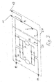
- Adsorption dryers are used when the compressed air system is exposed to temperatures below freezing or when a particularly low pressure dew point is required for special applications.
- the air is passed through a container 7 filled with desiccant (activated alumina), where the water vapor accumulates on the surface of the desiccant.
- desiccant activated alumina
- the dryers have two adsorption tanks 7.
- the compressed air supply is switched so that one container always dries, while the other container, which is not flowed through by compressed air, regenerates the desiccant.
- the regeneration of the desiccant takes place by means of a blower 9 and a mostly electrically operated heater 10.
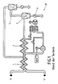
- FIG. 3 A flow diagram of the arrangement according to the invention is shown in FIG. 3 shown.
- the moist air enters the refrigeration dryer 20 at the inlet 11 at a pressure of 7 bar and at a temperature of around +35 ° C.
- the air is cooled to about +3 ° C. This condenses the water vapor. It can be separated in the integrated separating filter 4.
- the subsequent filtration of the air in the fine oil filter 6 ensures the absence of oil in the compressed air.
- the pressure dew point (DTP) is now +3 ° C.
- the temperature and the dew point of the air are congruent. Now the medium is saturated with moisture, ie the relative humidity of the air is 100%. The ideal state for the adsorbent used is thus achieved.
- the air enters the adsorption dryer 21 at an almost constant temperature.
- adsorption in the desiccant containers 7 drying on a DTP, depending on the design of -25 ° C to -40 ° C instead.
- the air through a particulate filter 8, which retains the desiccant abrasion, in turn fed to the refrigerant dryer 20 integrated air / air heat exchanger 1, which they then with a processing temperature, for example, from about +27 ° C, and with a DTP of -. 40 ° C and a pressure of 6.6 bar at the outlet 12 leaves.
- An outside temperature controlled compressed air bypass 15 allows the adsorption dryer 21 to circumnavigate as needed in the summer and only to put into operation during the winter months. As already mentioned, the far more favorable operating costs justify the slightly higher investment costs of the integrated refrigeration dryer.
- the refrigeration dryer which removes the main water load (85%) from the compressed air network is used up to a pressure dew point of +3 ° C.
- the energy and CO 2 savings effect is further enhanced with the outside temperature controlled compressed air bypass, with which the adsorber and the associated energy costs can be switched off completely in the summer.
Abstract
Description
Die Erfindung betrifft eine Gesamtheit von mehreren Trocknern für ein Gas, insbesondere für Druckluft, wobei jeder Trockner einen Kältetrockner und einen damit kombinierten, in den Kreislauf des Kältetrockners integrierbaren Adsorptionstrockner umfasst.The invention relates to a total of several dryers for a gas, in particular for compressed air, wherein each dryer comprises a refrigeration dryer and a combined with it, integrable in the cycle of the refrigerant dryer adsorption.
Derartige Trockner sind aus dem deutschen Gebrauchsmuster
Bestimmte Produktionsverfahren verlangen eine zuverlässig aufbereitete, qualitativ hochwertige Druckluft (z. B. Instrumentenluft, Luft für pneumatische Steuerungen und verfahrenstechnische Prozesse, Förderluft für den Transport von pulverförmigen Materialien in Chemie, Pharmazie, Lebensmitteltechnik etc.). Die Luft soll technisch ölfrei und darüber hinaus sehr trocken sein. Drucktaupunkte von unter 0 °C bis herab zu -40 °C werden i. d. R. angestrebt. Wird das Arbeitsmedium Luft mit Drucktaupunkten oberhalb von +3 °C nun durch ein weit verzweigtes Rohrleitungsnetz oder streckenweise auch durch Freiluftleitungssysteme gefördert, sind Störungen durch eingefrorenes Kondensat nicht auszuschließen und besonders in den Wintermonaten an der Tagesordnung. Anlagenstillstände oder Qualitätseinbrüche innerhalb der Produktion, in jedem Fall aber erhebliche Folgekosten sind dann die unangenehmen und teuren Auswirkungen, die es zu vermeiden gilt.Certain production processes require reliable, high-quality compressed air (eg instrument air, air for pneumatic controls and process engineering, conveying air for the transport of powdered materials in chemistry, pharmacy, food technology, etc.). The air should be technically oil-free and also very dry. Pressure dew points from below 0 ° C down to -40 ° C i. d. R. desired. If the working medium air with pressure dew points above +3 ° C is now conveyed through a widely branched pipeline network or in places also through open-air piping systems, disturbances due to frozen condensate can not be ruled out and are particularly common in the winter months. Plant downtimes or drops in quality within the production, but in any case significant consequential costs are the unpleasant and expensive effects that must be avoided.
Die wirtschaftliche Erzeugung von Drucktaupunkten unter 0 °C bei mittleren und großen Volumenströmen war bisher nur über "reine" Adsorptionstrockner möglich. Bei Volumenströmen über ca. 1.000 m3/h verwendete man weitestgehend warmregenerierende Adsorptionstrockner. Diese erscheinen zwar bezüglich ihres Anschaffungswertes im Vergleich zu kaltregenerierenden Adsorptionstrocknern zunächst als "teurer", rechnen sich jedoch schnell über den Unterhalt, das heißt durch ihre Betriebskosten.The economic production of pressure dew points below 0 ° C at medium and high flow rates was previously only possible with "pure" adsorption dryers. With volume flows over approx. 1.000 m 3 / h one used as far as possible heat-regenerating adsorption dryers. Although these appear to be "more expensive" in terms of their purchase value compared to cold-regenerating adsorption dryers, they quickly pay off over upkeep, that is, through their operating costs.
In der Vergangenheit hatten daher verschiedene Bestrebungen das Ziel, Adsorptionstrockner mit Warmregeneration wirtschaftlicher betreiben zu können.In the past, therefore, various endeavors aimed at more economically operating adsorption dryers with warm regeneration.
Mit der im eingangs genannten Gerauchsmuster
Bei dem bekannten kombinierten Kälte-Adsorptions-Trockner sind die beiden wesentlichen Einheiten, nämlich der Kältetrockner und der Adsorptionstrockner genau aufeinander abgestimmt, um die wirtschaftliche Zusammenarbeit der beiden Einheiten zu ermöglichen. Ein Anschluss dieses Adsorptionstrockners an einen anderen Kältetrockner, z. B. mit einer anderen Leistung, ist nicht möglich.In the known combined refrigeration adsorption dryer, the two essential units, namely the refrigerant dryer and the adsorption dryer are precisely matched to enable the economic cooperation of the two units. One connection of this adsorption dryer to another refrigeration dryer, z. B. with a different performance is not possible.
Der Erfindung liegt die Aufgabe zugrunde, das Prinzip des kombinierten Adsorptions-Kälte-Trockners erheblich vielseitiger anwendbar zu machen und damit für beliebige Trockner-Kombinationen eine deutliche Energieeinsparung und damit verbunden eine deutliche CO2-Reduktion zu erreichen.The invention has for its object to make the principle of the combined adsorption refrigeration dryer considerably more versatile and thus for any dryer combinations a significant energy savings and associated with achieving a significant CO 2 reduction.
Diese Aufgabe wird bei der eingangs genannten Gesamtheit von Trocknern dadurch gelöst, dass die Trockner zwar unterschiedliche Kältetrockner, aber jeweils den gleichen modellabhängigen Adsorptionstrockner umfassen. Es handelt sich um eine Modulbauweise. Durch die Verwendung immer des gleichen modellabhängigen Adsorptionstrockners ist der Herstellungsaufwand, auch bei Kombination mit unterschiedlichen Kältetrocknern erheblich niedriger, als wenn für jeden unterschiedlichen Typ von Kältetrockner ein speziell darauf ausgelegter, ebenfalls unterschiedlicher Adsorptionstrockner vorgesehen ist.This object is achieved in the case of the aforementioned totality of dryers in that the dryers comprise different refrigeration dryers, but in each case the same model-dependent adsorption dryer. It is a modular construction. By using always the same model-dependent adsorption dryer is the Production cost, even when combined with different refrigeration dryers considerably lower than if a specially designed, also different adsorption dryer is provided for each different type of refrigeration dryer.
Aus folgendem Grund ist es erfindungsgemäß möglich, immer den gleichen Adsorptionstrockner bei unterschiedlichen Kältetrocknern einzusetzen: Der Adsorptionstrockner benötigt lediglich den Betriebsdruck und den volumenstrom als Führungsgröße und muss nicht an die Umgebungsbedingungen seines jeweiligen Standorts angepasst sein. Der Kältetrockner hat die Aufgabe, den benötigten +3 °C Drucktaupunkt bei 100 % Sättigung bereitzustellen. Um die weltweit höchst unterschiedlichen Bedingungen für Umgebungstemperaturen und Drucklufteintrittstemperaturen zu bewältigen, sind unterschiedliche Kältetrockner mit unterschiedlichen Leistungen notwendig.For the following reason, it is possible according to the invention to always use the same adsorption dryer with different refrigeration dryers: The adsorption dryer only requires the operating pressure and the volume flow as a reference variable and does not have to be adapted to the ambient conditions of its respective location. The purpose of the refrigeration dryer is to provide the required +3 ° C dew point at 100% saturation. In order to cope with the world-wide very different conditions for ambient temperatures and compressed air inlet temperatures, different refrigeration dryers with different capacities are necessary.
Weiterhin ist hervorzuheben, dass der Adsorptionstrockner zuschaltbar ist und dass der Trockner eine Steuereinheit aufweist, die bei Unterschreiten einer vorgegebenen Außentemperatur den Adsorptionstrockner zuschaltet.It should also be emphasized that the adsorption dryer can be switched on and that the dryer has a control unit which switches on the adsorption dryer when the temperature falls below a predetermined outside temperature.
Die Erfindung wird nachfolgend anhand eines Ausführungsbeispiels näher erläutert, wobei zum besseren Verständnis auch der Stand der Technik erläutert wird. Es zeigen
- Figur 1
- ein Fließbild eines Kälte-Drucklufttrockners nach dem Stand der Technik,
Figur 2- ein Fließbild eines Adsorptionstrockners, ebenfalls nach dem Stand der Technik, und
Figur 3- ein Fließbild des erfindungsgemäßen kombinierten Kälte- und Adsorptionstrockners nach einem erfindungsgemäßen Ausführungsbeispiel.
- FIG. 1
- a flow diagram of a refrigeration compressed air dryer according to the prior art,
- FIG. 2
- a flow diagram of an adsorption dryer, also according to the prior art, and
- FIG. 3
- a flow diagram of the combined refrigeration and adsorption dryer according to the invention according to an embodiment of the invention.
In allen Zeichnungen haben gleiche Bezugszeichen die gleiche Bedeutung und werden daher gegebenenfalls nur einmal erläutert.In all drawings, like reference numerals have the same meaning and therefore may be explained only once.
Sie werden in Bereichen eingesetzt, in denen das Druckluftnetz ausschließlich Temperaturen oberhalb des Gefrierpunktes ausgesetzt ist. Warme, gesättigte Druckluft tritt in den Luft/Luft-Wärmetauscher 1 ein und wird im Kältemittel/Luft-Wärmetauscher 2 weiter abgekühlt, der mittels eines Expansionsventils gesteuert wird. Wasserdampf kondensiert zu Flüssigkeit und wird zuverlässig im Grad-9-Abscheider/Filter 3 von der Druckluft getrennt und durch den vollautomatisch arbeitenden Kondensatableiter 4 abgeschieden. Die nun kalte und trockene Druckluft wird genutzt, um im Luft/Luft-Wärmetauscher 1 die eintretende warme Druckluft abzukühlen.They are used in areas where the compressed air network is only exposed to temperatures above freezing point. Warm, saturated compressed air enters the air / air heat exchanger 1 and is further cooled in the refrigerant /
Adsorptionstrockner kommen zum Einsatz, wenn das Druckluftsystem Temperaturen unterhalb des Gefrierpunktes ausgesetzt oder wenn für spezielle Applikationen ein besonders niedriger Drucktaupunkt erforderlich ist.Adsorption dryers are used when the compressed air system is exposed to temperatures below freezing or when a particularly low pressure dew point is required for special applications.
Die Luft wird durch einen mit Trockenmittel (aktiviertes Aluminiumoxid) befüllten Behälter 7 geführt, wo sich der Wasserdampf auf der Oberfläche des Trockenmittels anlagert.The air is passed through a
Diese Trockenmittel können regeneriert und immer wieder eingesetzt werden. Die Trockner verfügen über zwei Adsorptionsbehälter 7. Die Druckluftzuführung wird umgeschaltet, so dass immer ein Behälter trocknet, während der andere Behälter, der nicht von Druckluft durchströmt wird, das Trockenmittel regeneriert. Bei warmregenerierenden Adsorptionstrocknern erfolgt mittels eines Gebläses 9 und einer meist elektrisch betriebenen Heizung 10 die Regeneration des Trockenmittels.These desiccants can be regenerated and used again and again. The dryers have two
Ein Fließbild der erfindungsgemäßen Anordnung ist in
Das Funktionsprinzip: Die feuchte Luft tritt am Eintritt 11 mit einem Druck von 7 bar und mit einer Temperatur von rund +35 °C in den Kältetrockner 20 ein. Im Luft/Luft-Wärmetauscher 1 und nachfolgend im Kältemittel/Luft-Wärmetauscher 2 wird die Luft auf etwa +3 °C abgekühlt. Dabei kondensiert der Wasserdampf. Er lässt sich im integrierten Abscheidefilter 4 trennen. Die anschließende Filtration der Luft im Ölfeinstfilter 6 stellt die Ölfreiheit der Druckluft sicher. Nach dieser Vorbehandlung verlässt die Luft den Kältetrockner 20, der Drucktaupunkt (DTP) liegt nun bei +3 °C. Die Temperatur und der Taupunkt der Luft sind deckungsgleich. Jetzt ist das Medium feuchtigkeitsgesättigt, das heißt, die relative Feuchte der Luft beträgt 100 %. Der Idealzustand für das verwendete Adsorbent ist damit erreicht.The operating principle: The moist air enters the
Danach tritt die Luft mit nahezu gleich bleibender Temperatur in den Adsorptionstrockner 21 ein. Hier findet durch Adsorption in den Trockenmittelbehältern 7 die Trocknung auf einen DTP, je nach Auslegung von -25 °C bis -40 °C, statt. Anschließend wird die Luft durch einen Partikelfilter 8, der den Trockenmittelabrieb zurückhält, dem wiederum im Kältetrockner 20 integrierten Luft/Luft-Wärmetauscher 1 zugeführt, den sie dann mit einer verarbeitungsgerechten Temperatur, beispielsweise von etwa +27 °C, und mit einem DTP von -40 °C und einem Druck von 6,6 bar am Austritt 12 verlässt.Thereafter, the air enters the
Ein außentemperaturgesteuerter Druckluft-Bypass 15 ermöglicht, den Adsorptionstrockner 21 je nach Bedarf im Sommer zu umfahren und nur während der Wintermonate in Betrieb zu nehmen. Wie bereits erwähnt, rechtfertigen die weitaus günstigeren Betriebskosten die geringfügig höheren Investitionskosten des integrierten Kältetrockners.An outside temperature controlled
Wesentlich für die Wirtschaftlichkeit der Kombination sind folgende Merkmale des Anlagenaufbaus:
- Niedrigste Betriebskosten im Vergleich zu üblichen Adsorptionstrocknern (warm- und kaltregenerierend)
- Wählbarer "Sommer-Winterbetrieb", der zusätzliches signifikantes Einsparpotential bietet
- Konstanter Drucktaupunkt
- Vermeidung von Drucktaupunkt- und Temperaturspitzen beim Umschalten der Trockenmittelbehälter 7
- Geringste Druckluftverluste
- Effizienteste Ölfiltration an der kältesten Stelle "Cold Coalescing"
- Längere Lebensdauer des Adsorbents durch extrem niedrige Regenerationstemperaturen und lange Zykluszeiten (16 h)
- Einsatz der besonders vorteilhaften HANKISON Digital Scroll® Technologie, sowie Automatic Purge Saving (APS) für die Energieeinsparung in Teillastsituationen
- Kompakte Bauweise, die beispielsweise auch in (On-Site) Containerstationen zur Anwendung kommen kann
- Optimale Austrittstemperaturen
- Lowest operating costs compared to conventional adsorption dryers (hot and cold regenerating)
- Selectable "summer-winter operation", which offers additional significant savings potential
- Constant pressure dew point
- Avoidance of pressure dew point and temperature peaks when switching the
desiccant 7 - Lowest compressed air losses
- Most efficient oil filtration at the coldest point "Cold Coalescing"
- Longer life of the adsorbent due to extremely low regeneration temperatures and long cycle times (16 h)
- Use of the particularly advantageous HANKISON Digital Scroll® technology as well as Automatic Purge Saving (APS) for energy saving in partial load situations
- Compact design, which can also be used, for example, in (on-site) container stations
- Optimal outlet temperatures
Zusammengefasst lässt sich feststellen: Bei der erfindungsgemäßen Druckluftaufbereitung wird bis zu einem Drucktaupunkt von +3 °C das nach wie vor wirtschaftlichste System, der Kältetrockner, genutzt, welcher die Hauptwasserbeladung (85 %) aus dem Druckluftnetz entfernt. Die geschickte Integration des Adsorberteils, der wiederum bei der höchst möglichen Wasseraufnahmekapazität des Adsorbents eingebunden wird, erzeugt so mit einem Bruchteil an Adsorptionsmittelfüllung, an Energie für die Regenerations-Heizung sowie für das Regenerations-Gebläse (Energieeinsparung = CO2-Reduktion) die gleiche Druckluftqualität wie ein für Standardbedingungen ausgelegter Adsorber. Dies ermöglicht eine moderne Druckluftaufbereitung bei geforderten Drucktaupunkten unter 0 °C und Volumenströmen ab etwa 1.000 m3/h.In summary, it can be stated: In the compressed air preparation according to the invention, the still most economical system, the refrigeration dryer, which removes the main water load (85%) from the compressed air network is used up to a pressure dew point of +3 ° C. The clever integration of the adsorber, which in turn is involved in the highest possible water absorption capacity of the adsorbent generated so with a fraction of adsorbent, energy for the regeneration heater and for the regeneration blower (energy conservation = CO 2 reduction) the same compressed air quality like an adsorber designed for standard conditions. This allows modern compressed air treatment at required pressure dew points below 0 ° C and flow rates from about 1,000 m 3 / h.
Der Energie- und CO2-Einspareffekt wird nochmals mit dem außentemperaturgesteuerten Druckluftbypass verstärkt, mit dem der Adsorberteil und die damit verbundenen Energiekosten im Sommer gänzlich weggeschaltet werden können.The energy and CO 2 savings effect is further enhanced with the outside temperature controlled compressed air bypass, with which the adsorber and the associated energy costs can be switched off completely in the summer.
- 11
- Luft/Luft-WärmetauscherAir / air heat exchanger
- 22
- Kältemittel/Luft-WärmetauscherRefrigerant / air heat exchanger
- 33
- Grad-9-Abscheider/FilterGrade 9 trap / filter
- 44
- KondensatableiterSteam Traps
- 55
-
Optionaler Grad-5-Öl-Fein-Filter
Optional grade 5 oil fine filter - 66
- Ölfeinstfilteroil microfilter
- 77
- TrockenmittelbehälterDesiccant container
- 88th
- Partikelfilterparticulate Filter
- 99
- Gebläsefan
- 1010
- Heizungheater
- 1111
- DrucklufteintrittCompressed air inlet
- 1212
- DruckluftaustrittCompressed air outlet
- 1313
- FrischlufteintrittFresh air inlet
- 1414
- RegenerationsluftaustrittRegeneration air outlet
- 1515
- Bypassbypass
- 2020
- Kälte-DrucklufttrocknerRefrigeration compressed air dryer
- 2121
- Adsorptionstrockner warmregeneriertAdsorption dryer warm regenerated
Claims (2)
dadurchgekennzeichnet,
dass die Trockner unterschiedliche Kältetrockner (20), aber jeweils den gleichen Adsorptionstrockner (21) umfassen.Assembly of a plurality of dryers for a gas, in particular for compressed air, each dryer comprising a refrigeration dryer and an adsorption dryer combined with it, which can be integrated into the circuit of the refrigeration dryer,
characterized,
in that the driers comprise different refrigerating driers (20) but in each case the same adsorption drier (21).
dadurch gekennzeichnet,
dass der Adsorptionstrockner (21) zuschaltbar ist und dass der Trockner eine Steuereinheit aufweist, die bei Unterschreiten einer vorgegebenen Außentemperatur den Adsorptionstrockner (21) zuschaltet.Dryer according to claim 1,
characterized,
that the adsorption dryer (21) is switched on and that the dryer comprises a control unit, which switches the adsorption dryer (21) falls below a predetermined outdoor temperature.
Applications Claiming Priority (2)
| Application Number | Priority Date | Filing Date | Title |
|---|---|---|---|
| DE202008005228 | 2008-04-15 | ||
| DE202008006346U DE202008006346U1 (en) | 2008-04-15 | 2008-05-08 | Set of several dryers for one gas |
Publications (1)
| Publication Number | Publication Date |
|---|---|
| EP1994975A1 true EP1994975A1 (en) | 2008-11-26 |
Family
ID=39768755
Family Applications (1)
| Application Number | Title | Priority Date | Filing Date |
|---|---|---|---|
| EP08014682A Withdrawn EP1994975A1 (en) | 2008-04-15 | 2008-08-19 | Assembly of a plurality of gas dryers |
Country Status (1)
| Country | Link |
|---|---|
| EP (1) | EP1994975A1 (en) |
Cited By (2)
| Publication number | Priority date | Publication date | Assignee | Title |
|---|---|---|---|---|
| ITPN20090039A1 (en) * | 2009-06-19 | 2010-12-20 | Parker Hiross S P A | "PROCEDURE AND APPARATUS FOR GAS COMPRESSED DRYING" |
| FR3011915A1 (en) * | 2013-10-10 | 2015-04-17 | Air Liquide | METHOD AND APPARATUS FOR AIR SEPARATION BY CRYOGENIC DISTILLATION FOR THE PRODUCTION OF GASEOUS NITROGEN |
Citations (4)
| Publication number | Priority date | Publication date | Assignee | Title |
|---|---|---|---|---|
| DE1240821B (en) * | 1963-07-27 | 1967-05-24 | Chlorator G M B H | Method and device for the continuous drying of gas flows |
| DE9201713U1 (en) | 1992-02-12 | 1992-06-17 | Hankison Gmbh, 4130 Moers, De | |
| DE10355927A1 (en) * | 2003-11-29 | 2005-06-30 | Tepcon Engineering Gesellschaft Mbh | Method for operating drier combination comprising cold drier and adsorption drier with adsorption tanks operated alternately in adsorption and regeneration phases comprises controlling phases to prevent freezing up |
| WO2006081635A1 (en) * | 2005-02-01 | 2006-08-10 | Atlas Copco Airpower, Naamloze Vennootschap | Gas drying device . |
-
2008
- 2008-08-19 EP EP08014682A patent/EP1994975A1/en not_active Withdrawn
Patent Citations (4)
| Publication number | Priority date | Publication date | Assignee | Title |
|---|---|---|---|---|
| DE1240821B (en) * | 1963-07-27 | 1967-05-24 | Chlorator G M B H | Method and device for the continuous drying of gas flows |
| DE9201713U1 (en) | 1992-02-12 | 1992-06-17 | Hankison Gmbh, 4130 Moers, De | |
| DE10355927A1 (en) * | 2003-11-29 | 2005-06-30 | Tepcon Engineering Gesellschaft Mbh | Method for operating drier combination comprising cold drier and adsorption drier with adsorption tanks operated alternately in adsorption and regeneration phases comprises controlling phases to prevent freezing up |
| WO2006081635A1 (en) * | 2005-02-01 | 2006-08-10 | Atlas Copco Airpower, Naamloze Vennootschap | Gas drying device . |
Cited By (4)
| Publication number | Priority date | Publication date | Assignee | Title |
|---|---|---|---|---|
| ITPN20090039A1 (en) * | 2009-06-19 | 2010-12-20 | Parker Hiross S P A | "PROCEDURE AND APPARATUS FOR GAS COMPRESSED DRYING" |
| EP2263778A1 (en) | 2009-06-19 | 2010-12-22 | Parker Hiross S.p.A. | Method and apparatus for drying compressed gases |
| FR3011915A1 (en) * | 2013-10-10 | 2015-04-17 | Air Liquide | METHOD AND APPARATUS FOR AIR SEPARATION BY CRYOGENIC DISTILLATION FOR THE PRODUCTION OF GASEOUS NITROGEN |
| WO2015052444A3 (en) * | 2013-10-10 | 2016-01-14 | L'air Liquide, Societe Anonyme Pour L'etude Et L'exploitation Des Procedes Georges Claude | Method and device for separating air by cryogenic distillation in order to produce nitrogen gas |
Similar Documents
| Publication | Publication Date | Title |
|---|---|---|
| EP1926400B1 (en) | Method and apparatus for creating an air-conditioned atmosphere | |
| DE102014108977A1 (en) | Apparatus and method for drying gases | |
| DE2702701A1 (en) | METHOD FOR RECOVERING WATER FROM HUMID AIR AND SYSTEM FOR IMPLEMENTING THE METHOD | |
| EP1821042A2 (en) | Dehumidification device | |
| DE3814175A1 (en) | METHOD AND ARRANGEMENT FOR REGENERATING ADSORPTION MATERIAL | |
| DE10028030A1 (en) | Sorption device for heating and cooling gas flows | |
| DE102006054875A1 (en) | Conditioning device for the supply air flow of a drying booth of a paint shop and method for conditioning the supply air flow | |
| DE102006022293A1 (en) | Drying of compressed air using the compressor heat with closed regeneration cycle | |
| DE102012112040B4 (en) | Apparatus and method for drying gases | |
| DE102006023161B4 (en) | Drying of compressed air using external heat with closed regeneration cycle | |
| DE602004005472T2 (en) | METHOD FOR DISCONNECTING GASES FROM A GAS MIXTURE AND DEVICE FOR APPLYING SUCH A METHOD | |
| EP1994975A1 (en) | Assembly of a plurality of gas dryers | |
| EP2162687A1 (en) | Refrigerating machine comprising different sorption materials | |
| CN207438936U (en) | A kind of two-way bypasses three-level auto-cascading refrigeration system | |
| EP2626125B1 (en) | Device for drying and filtering a gas | |
| DE202008006346U1 (en) | Set of several dryers for one gas | |
| DE3150624A1 (en) | Process and equipment for separating a crude gas mixture | |
| CH691349A5 (en) | Continuous drying of air to low dew point comprises combining refrigeration circuit with regenerative sorption dehumidifier | |
| DE10355927A1 (en) | Method for operating drier combination comprising cold drier and adsorption drier with adsorption tanks operated alternately in adsorption and regeneration phases comprises controlling phases to prevent freezing up | |
| DE102004063840B3 (en) | A method for air conditioning a room or motor vehicle interior has a heat pump in which the compressed or low pressure air is exhausted for cooling or heating | |
| DE19548458A1 (en) | Method for cooling and dehumidifying room air | |
| DE112009000657B4 (en) | Method for operating a cooling device and cooling device for carrying out such a method | |
| DE10358260B4 (en) | Drying process, especially for thermolabile products | |
| CN219984275U (en) | Freezing type air dryer | |
| DE202017105468U1 (en) | Heat exchange device |
Legal Events
| Date | Code | Title | Description |
|---|---|---|---|
| PUAI | Public reference made under article 153(3) epc to a published international application that has entered the european phase |
Free format text: ORIGINAL CODE: 0009012 |
|
| AK | Designated contracting states |
Kind code of ref document: A1 Designated state(s): AT BE BG CH CY CZ DE DK EE ES FI FR GB GR HR HU IE IS IT LI LT LU LV MC MT NL NO PL PT RO SE SI SK TR |
|
| AX | Request for extension of the european patent |
Extension state: AL BA MK RS |
|
| AKX | Designation fees paid | ||
| STAA | Information on the status of an ep patent application or granted ep patent |
Free format text: STATUS: THE APPLICATION IS DEEMED TO BE WITHDRAWN |
|
| 18D | Application deemed to be withdrawn |
Effective date: 20090527 |
|
| REG | Reference to a national code |
Ref country code: DE Ref legal event code: 8566 |