EP1993640B1 - Chirurgisches instrument - Google Patents
Chirurgisches instrument Download PDFInfo
- Publication number
- EP1993640B1 EP1993640B1 EP07762580.4A EP07762580A EP1993640B1 EP 1993640 B1 EP1993640 B1 EP 1993640B1 EP 07762580 A EP07762580 A EP 07762580A EP 1993640 B1 EP1993640 B1 EP 1993640B1
- Authority
- EP
- European Patent Office
- Prior art keywords
- handle
- malleable member
- tunneling
- cable
- post
- Prior art date
- Legal status (The legal status is an assumption and is not a legal conclusion. Google has not performed a legal analysis and makes no representation as to the accuracy of the status listed.)
- Not-in-force
Links
- 230000005641 tunneling Effects 0.000 claims description 50
- 206010033675 panniculitis Diseases 0.000 claims description 23
- 230000037361 pathway Effects 0.000 claims description 23
- 210000004304 subcutaneous tissue Anatomy 0.000 claims description 23
- 238000003780 insertion Methods 0.000 claims description 19
- 230000037431 insertion Effects 0.000 claims description 19
- 239000007943 implant Substances 0.000 claims description 11
- 238000000034 method Methods 0.000 description 35
- 210000001519 tissue Anatomy 0.000 description 14
- 239000000463 material Substances 0.000 description 7
- 238000001356 surgical procedure Methods 0.000 description 7
- 210000000115 thoracic cavity Anatomy 0.000 description 5
- 230000008901 benefit Effects 0.000 description 4
- 208000015181 infectious disease Diseases 0.000 description 4
- 230000003213 activating effect Effects 0.000 description 3
- 206010019280 Heart failures Diseases 0.000 description 2
- XAGFODPZIPBFFR-UHFFFAOYSA-N aluminium Chemical compound [Al] XAGFODPZIPBFFR-UHFFFAOYSA-N 0.000 description 2
- 229910052782 aluminium Inorganic materials 0.000 description 2
- 238000012986 modification Methods 0.000 description 2
- 230000004048 modification Effects 0.000 description 2
- 230000002861 ventricular Effects 0.000 description 2
- 210000001015 abdomen Anatomy 0.000 description 1
- 210000000683 abdominal cavity Anatomy 0.000 description 1
- 239000008280 blood Substances 0.000 description 1
- 210000004369 blood Anatomy 0.000 description 1
- 206010007625 cardiogenic shock Diseases 0.000 description 1
- 238000004891 communication Methods 0.000 description 1
- 239000000356 contaminant Substances 0.000 description 1
- 230000008878 coupling Effects 0.000 description 1
- 238000010168 coupling process Methods 0.000 description 1
- 238000005859 coupling reaction Methods 0.000 description 1
- 238000013461 design Methods 0.000 description 1
- 208000014674 injury Diseases 0.000 description 1
- 230000000149 penetrating effect Effects 0.000 description 1
- 230000008569 process Effects 0.000 description 1
- 230000002035 prolonged effect Effects 0.000 description 1
- 238000005086 pumping Methods 0.000 description 1
- 238000011084 recovery Methods 0.000 description 1
- 229910001220 stainless steel Inorganic materials 0.000 description 1
- 239000010935 stainless steel Substances 0.000 description 1
- 230000008733 trauma Effects 0.000 description 1
Images


Classifications
-
- A—HUMAN NECESSITIES
- A61—MEDICAL OR VETERINARY SCIENCE; HYGIENE
- A61B—DIAGNOSIS; SURGERY; IDENTIFICATION
- A61B17/00—Surgical instruments, devices or methods
- A61B17/32—Surgical cutting instruments
- A61B17/320016—Endoscopic cutting instruments, e.g. arthroscopes, resectoscopes
-
- A—HUMAN NECESSITIES
- A61—MEDICAL OR VETERINARY SCIENCE; HYGIENE
- A61B—DIAGNOSIS; SURGERY; IDENTIFICATION
- A61B17/00—Surgical instruments, devices or methods
- A61B17/04—Surgical instruments, devices or methods for suturing wounds; Holders or packages for needles or suture materials
- A61B17/06—Needles ; Sutures; Needle-suture combinations; Holders or packages for needles or suture materials
- A61B17/06066—Needles, e.g. needle tip configurations
- A61B17/06109—Big needles, either gripped by hand or connectable to a handle
-
- A—HUMAN NECESSITIES
- A61—MEDICAL OR VETERINARY SCIENCE; HYGIENE
- A61B—DIAGNOSIS; SURGERY; IDENTIFICATION
- A61B17/00—Surgical instruments, devices or methods
- A61B17/00008—Vein tendon strippers
-
- A—HUMAN NECESSITIES
- A61—MEDICAL OR VETERINARY SCIENCE; HYGIENE
- A61B—DIAGNOSIS; SURGERY; IDENTIFICATION
- A61B17/00—Surgical instruments, devices or methods
- A61B17/34—Trocars; Puncturing needles
- A61B17/3415—Trocars; Puncturing needles for introducing tubes or catheters, e.g. gastrostomy tubes, drain catheters
-
- A—HUMAN NECESSITIES
- A61—MEDICAL OR VETERINARY SCIENCE; HYGIENE
- A61B—DIAGNOSIS; SURGERY; IDENTIFICATION
- A61B17/00—Surgical instruments, devices or methods
- A61B2017/0046—Surgical instruments, devices or methods with a releasable handle; with handle and operating part separable
-
- A—HUMAN NECESSITIES
- A61—MEDICAL OR VETERINARY SCIENCE; HYGIENE
- A61B—DIAGNOSIS; SURGERY; IDENTIFICATION
- A61B17/00—Surgical instruments, devices or methods
- A61B17/32—Surgical cutting instruments
- A61B2017/320044—Blunt dissectors
-
- A—HUMAN NECESSITIES
- A61—MEDICAL OR VETERINARY SCIENCE; HYGIENE
- A61B—DIAGNOSIS; SURGERY; IDENTIFICATION
- A61B17/00—Surgical instruments, devices or methods
- A61B17/32—Surgical cutting instruments
- A61B2017/320056—Tunnelers
Definitions
- a left ventricular assist device which enables heart failure patients to return to prolonged and productive lives.
- a left ventricular assist device (“LVAD”) is a battery-operated, mechanical pump-type device that is surgically implanted. It helps maintain the pumping ability of a heart that cannot effectively work on its own.
- a LVAD typically includes an electrical cable which is hardwired into the LVAD and routed through a patient's body to an external controller and battery.
- the surgical procedure of creating a channel or "tunnel" for routing the electrical cable through the body is commonly called “tunneling.”
- the "tunneling" procedure is an invasive procedure that can lead to infection. Therefore, to minimize the risk of infection and to provide a secure mechanical attachment between the electrical cable and the surrounding tissue, the tunneling channel or path is typically made smaller in size than the electrical connector attached at an end of the electrical cable.
- the electrical connector is the part of the electrical cable that plugs into or engages the external controller. Usually, the electrical connector is larger in size than the flexible body portion of the electrical cable. As a result, the force required to physically pull the electrical cable through a patient's body is relatively high.
- the tunneling path is created by a tunneling tool, which starts forming the tunnel on the outside of the patient's body.
- the tunnel goes through the abdominal cavity and up into the thoracic cavity near the LVAD and heart.
- the electrical cable is tied to the tunneling tool by a suture or other means. The electrical cable is then dragged or pulled back through the tunneling path using the tunneling tool until a suitable length of the electrical cable extends from the patient's body to connect the electrical cable to the external controller.
- US5306240A (Pilling Co) describes a tunneler for placement of an arteriovenous graft in subcutaneous tissue of a patient.
- the tunneler includes a shaft with opposite ends carrying a penetrating tip and a handle.
- Both of the tunneling procedures described above and other similar procedures employ a relatively high force to pull or drag the electrical cable through the tunnel or path formed in the patient's body.
- the high stress on the tissues of the body cause trauma to the issues and could lead to complications, infection and extended recovery time for patients.
- the present invention is directed to a surgical tool and, more specifically, to a surgical tunneling device for creating a pathway in the subcutaneous tissue of the body which is easy to use and adaptable for use in different tunneling procedures.
- the tunneling device includes a tip removably connected to each of the ends.
- the tips respectively defining the insertion surface, where at least a portion of each of the ends defines a plurality of threads, and where each of the tips is threadingly engaged with one of the ends of the malleable member.
- the handle includes an actuator, where the actuator is operable to cause the handle to engage with or dis-engage from one of the ends.
- the tunneling system includes a malleable member having a first end and a second end. Each of the ends defines an insertion surface that facilitates the insertion of the first and second ends into the subcutaneous tissue of the person's body.
- the tunneling device includes an interchangeable handle connectable to each of the first and second ends. The handle defines a grasping surface and an opening. The opening is configured to receive either of the first and second ends and the grasping surface enables a user to securely hold the handle with one hand.
- the tunneling system also includes a coupler operable to join one of the first and second ends of the malleable member and an end of a cable of an implant device to secure the malleable member and the cable together.
- the handle is operable to enable a user to forcibly move the malleable member through the subcutaneous tissue of the person's body to create the pathway in the subcutaneous tissue and enable the user to pull the cable of the implant device through the created pathway.
- the handle includes a post and a spring positioned between the post and the actuator.
- the post has a first diameter and a second smaller diameter.
- the post is initially positioned adjacent to the first end of the malleable member inserted in the handle to prevent the first end from being removed from the handle.
- the spring biases the post inwardly to cause the second diameter of the post to be positioned adjacent to the first end of the malleable member to enable the first end of the malleable member to be removed from the handle.
- the insertion surface of at least one of the tips is a tapered surface.
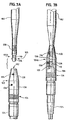
- each end 104a and 104b includes a threaded portion 108 which is threadingly engaged with corresponding threads 142 formed on a portion of the tips 106.
- a cap screw 142 is inserted into an end of the removable tip.
- the cap screw 142 includes a threaded portion 143 and a head 144.
- the threaded portion 143 extends through an opening defined by rotating collar 138 and is screwed into the corresponding threaded portions 108 of one or both ends 104a and 104b to hold or secure the collar 138 to the ends 104a and 104b.
- the handle or grip 112 is connectable to each end 104a and 104b and more specifically, to each tip 106 connected to the ends of the malleable member 102.
- the handle 112 includes an input, button or actuator 114, a spring 116 positioned adjacent to the actuator and an engagement shaft or post 118 which is positioned adjacent to the spring 116.
- the handle defines an opening 120 which is positioned on an axis that is transverse to the axis defined by the engagement shaft or post. As shown in Fig. 3 , the handle defines end openings 113a and 113b and channel 113c.
- the handle 112 is made of 6061 anodized aluminum. It should be appreciated that the handle may be made of any suitable material or materials.
- the post 118 includes a first diameter 119a and a second diameter 119b. In one embodiment, the first diameter is larger than the second diameter. It should be appreciated that the post may have any suitable number of diameters and the diameters may be the same or different.
- the handle further defines a grasping or holding surface 117 which is grasped by a user's hand to forcibly push or pull the malleable member 102.
- the first diameter 119a of the engagement shaft or post 118 engages the groove 110 defined by the tip 106 in such a way that the tip 106 of the malleable member 102 cannot be pulled out of the opening 120 defined by the handle 112.
- the end 104a and more specifically, the tip 106 of the malleable member 102 is secured to the handle 112.
- the button or actuator 114 is activated or pressed to cause the spring 116 to bias the post 118 inwardly within the handle 112. This causes the smaller second diameter section 119b of the post 118 to be positioned over the tip 106 of the malleable member 102.
- a cap, coupler or coupling device 122 is connected to an end 126 of a cable such as an electrical cable associated with an implant device inserted in a person's body to enable one of the tips 106 of the malleable member 102 to be connected or coupled to the cable 124 to move, pull or push the cable through a tunnel or pathway created by the tunneling device 100 in the body and to minimize or prevent tissues and other contaminants from accumulating on an end of the cable.
- the coupler 122 includes an angled or tapered portion 128 which defines an opening 132 to receive the end 104b of the malleable member 102.
- the coupler 122 also includes a straight portion or bottom portion 130 which includes a set screw 134.
- the button 114 is released to secure the handle 112 to the end of the malleable member 102 as described above.
- the handle 112 is attached to an end 104a or 104b, and more specifically, one of the tips 106 of the malleable member 102 using a single hand which saves time during the surgical procedure.
- the user holds onto the grasping surface 117 of the handle and pulls the handle away from the body to correspondingly pull the inserted end 104a or 104b, or tip 106 of the malleable member 102 and the coupled cable 124 through the tunneled pathway.
- the cable 124 is pulled through the tunneled pathway by the tunneling device 100 until the cable is pulled a sufficient distance out of the patient's body so that the cable can be connected to a suitable controller, battery or the like.
- the handle 112 is then connected on the other end of the malleable member 102 (i.e., the inserted end) by pressing the button 114 and inserting that end or tip of the malleable member 102 into the opening 120 defined by the handle 112.
- the present invention therefore enables the tunneling device 100 to be used for any surgical tunneling procedure to create a tunnel or pathway in the patient's body.
- the cable 124 is coupled to the malleable member near the thoracic cavity, and the cable 124 is pulled through the body by pulling on the handle as described above.
- the tunneling device 100 of the present invention is adaptable to be used in any surgical procedure for creating a tunnel or pathway in the tissue of the body.
- the tunneling device 100 of the present invention also enables a user to employ a one-handed operation which saves valuable time during a surgical procedure.
Landscapes
- Health & Medical Sciences (AREA)
- Surgery (AREA)
- Life Sciences & Earth Sciences (AREA)
- Medical Informatics (AREA)
- Nuclear Medicine, Radiotherapy & Molecular Imaging (AREA)
- Engineering & Computer Science (AREA)
- Biomedical Technology (AREA)
- Heart & Thoracic Surgery (AREA)
- Molecular Biology (AREA)
- Animal Behavior & Ethology (AREA)
- General Health & Medical Sciences (AREA)
- Public Health (AREA)
- Veterinary Medicine (AREA)
- Orthopedic Medicine & Surgery (AREA)
- Surgical Instruments (AREA)
- Prostheses (AREA)
Claims (9)
- Tunnelvorrichtung (100) zum Erzeugen eines Pfads in subkutanem Gewebe des Körpers einer Person, wobei die Tunnelvorrichtung Folgendes umfasst:ein Element (102), das zwei Enden (104a, 104b) aufweist, wobei jedes der Enden mit einem Kragen (138) in Eingriff steht, wobei jeder Kragen (138) entfernbar mit einer entsprechenden Spitze (105) verbunden ist, wobei jede Spitze eine entsprechende Einführungsfläche (106) definiert, wobei jede Einführungsfläche konisch oder abgewinkelt ist, um das Einführen der Enden in das subkutane Gewebe des Körpers einer Person zu erleichtern, undeinen auswechselbaren Griff (112), der mit jedem der Enden verbunden werden kann, wobei der Griff eine Greiffläche (117) und eine Öffnung (120) definiert, wobei die Öffnung konfiguriert ist, um eines der Enden aufzunehmen, wobei die Greiffläche konfiguriert ist, damit ein Benutzer den Griff halten kann und dadurch das Element durch das subkutane Gewebe des Körpers einer Person zu bewegen, um den Pfad im subkutanen Gewebe zu erzeugen;dadurch gekennzeichnet, dass jede Spitze und der entsprechende Kragen (138) konfiguriert sind, um sich als Ganzes relativ zum Element (102) zu drehen, wenn sie verbunden sind.
- Tunnelvorrichtung (100) nach Anspruch 1, wobei mindestens ein Abschnitt (108) von jedem der Enden (104a, 104b) eine Vielzahl von Gewinden definiert, und wobei jede der Spitzen (105) mit einem der Enden des Elements (102) in Gewindeeingriff steht.
- Tunnelvorrichtung (100) nach Anspruch 1, die einen Koppler (122) beinhaltet, der mit einem der Enden des Elements (102) entfernbar verbunden ist, wobei der Koppler angepasst ist, um das Element an ein Ende eines Kabels (124) einer Implantatvorrichtung zu koppeln.
- Tunnelvorrichtung (100) nach Anspruch 1, wobei der Griff (112) einen Betätiger beinhaltet, wobei der Betätiger (114) betreibbar ist, um zu bewirken, dass der Griff mit einem der Enden (104a, 104b) in oder außer Eingriff steht.
- Tunnelvorrichtung (100) nach Anspruch 4, wobei der Griff einen Schaft (118) und eine Feder (116) beinhaltet, die zwischen dem Schaft und dem Betätiger (114) positioniert ist, wobei der Betätiger betreibbar ist, um die Feder zu komprimieren und zu bewirken, dass sich der Schaft in eine Position bewegt, wobei eines der Enden (104a, 104b) des Elements (102) in den Griff (112) eingeführt oder von ihm gelöst werden kann.
- Tunnelsystem zum Erzeugen eines Pfads in subkutanem Gewebe des Körpers einer Person, wobei das Tunnelsystem Folgendes umfasst:die Tunnelvorrichtung nach Anspruch 1; undeinen Koppler (122), der betreibbar ist, um eines des ersten und zweiten Endes des verformbaren Elements und ein Ende eines Kabels (124) einer Implantatvorrichtung zu verbinden, um das verformbare Element und das Kabel aneinander zu befestigen,wobei der Griff dem Benutzer erlaubt, das verformbare Element durch das subkutane Gewebe des Körpers einer Person zu bewegen, um den Pfad im subkutanen Gewebe zu erzeugen, und das Kabel der Implantatvorrichtung durch den erzeugten Pfad zu ziehen.
- System nach Anspruch 6, wobei der Griff (112) einen Betätiger (114), einen Stift (118) und eine Feder (116) beinhaltet, wobei die Feder zwischen dem Stift und dem Betätiger positioniert ist, wobei der Stift einen ersten Durchmesser (119a) und einen zweiten kleineren Durchmesser (119b) aufweist,
wobei der Stift anfänglich benachbart zum ersten Ende (104a) des verformbaren Elements (102) positioniert ist, das in den Griff (112) eingeführt wurde, um zu verhindern, dass das erste Ende aus dem Griff gelöst wird, und
wobei die Feder den Stift nach innen vorspannt, um zu bewirken, dass der zweite Durchmesser des Stifts benachbart zum ersten Ende des formbaren Elements positioniert werden kann, so dass das erste Ende des verformbaren Elements angepasst ist, um vom Griff gelöst zu werden. - System nach Anspruch 6, wobei mindestens ein Abschnitt von jeder der Spitzen (105) eine Vielzahl von Gewinden definiert, und wobei jede der Spitzen mit einem der Enden (104a, 104b) des verformbaren Elements (102) in Gewindeeingriff steht.
- System nach Anspruch 6, wobei der Koppler (122) eine Vielzahl von Verbindern (134, 136) beinhaltet, wobei ein erster Verbinder (134) der Vielzahl von Verbindern betreibbar ist, um den Koppler an das Ende des Kabels (124) zu befestigen und ein zweiter Verbinder (136) der Vielzahl von Verbindern betreibbar ist, um eines des ersten und zweiten Endes (104a, 104b) des verformbaren Elements am Koppler zu befestigen.
Applications Claiming Priority (2)
| Application Number | Priority Date | Filing Date | Title |
|---|---|---|---|
| US11/337,708 US8088138B2 (en) | 2006-01-23 | 2006-01-23 | Surgical tool |
| PCT/US2007/001743 WO2007087290A2 (en) | 2006-01-23 | 2007-01-23 | Surgical tool |
Publications (3)
| Publication Number | Publication Date |
|---|---|
| EP1993640A2 EP1993640A2 (de) | 2008-11-26 |
| EP1993640A4 EP1993640A4 (de) | 2015-02-18 |
| EP1993640B1 true EP1993640B1 (de) | 2018-05-16 |
Family
ID=38286492
Family Applications (1)
| Application Number | Title | Priority Date | Filing Date |
|---|---|---|---|
| EP07762580.4A Not-in-force EP1993640B1 (de) | 2006-01-23 | 2007-01-23 | Chirurgisches instrument |
Country Status (4)
| Country | Link |
|---|---|
| US (3) | US8088138B2 (de) |
| EP (1) | EP1993640B1 (de) |
| AU (1) | AU2007208365B2 (de) |
| WO (1) | WO2007087290A2 (de) |
Families Citing this family (28)
| Publication number | Priority date | Publication date | Assignee | Title |
|---|---|---|---|---|
| US9138228B2 (en) | 2004-08-11 | 2015-09-22 | Emory University | Vascular conduit device and system for implanting |
| US7846123B2 (en) | 2007-04-24 | 2010-12-07 | Emory University | Conduit device and system for implanting a conduit device in a tissue wall |
| WO2009014739A1 (en) * | 2007-07-23 | 2009-01-29 | Heartware, Inc. | Improved surgical tool |
| JP2011515159A (ja) * | 2008-03-18 | 2011-05-19 | レイク リージョン マニュファクチュアリング インコーポレイテッド | 皮下トンネル装置 |
| US20110118833A1 (en) * | 2009-11-15 | 2011-05-19 | Thoratec Corporation | Attachment device and method |
| US20110118829A1 (en) * | 2009-11-15 | 2011-05-19 | Thoratec Corporation | Attachment device and method |
| US8152845B2 (en) | 2009-12-30 | 2012-04-10 | Thoratec Corporation | Blood pump system with mounting cuff |
| US9381030B2 (en) | 2010-07-15 | 2016-07-05 | Nuvectra Corporation | Tunneling tool for implantable leads |
| US9968775B2 (en) * | 2010-12-09 | 2018-05-15 | Medtronic, Inc. | Method and apparatus for replacing lead extension without tunneling |
| JP6130302B2 (ja) | 2011-01-28 | 2017-05-17 | アピカ カーディオヴァスキュラー リミテッド | 組織壁の刺し傷を封止するシステム |
| AU2012212215B2 (en) | 2011-02-01 | 2015-07-30 | Emory University | Systems for implanting and using a conduit within a tissue wall |
| EP2995327A1 (de) | 2011-03-02 | 2016-03-16 | Thoratec Corporation | Ventrikuläre manschette |
| US9199019B2 (en) | 2012-08-31 | 2015-12-01 | Thoratec Corporation | Ventricular cuff |
| US9981076B2 (en) | 2012-03-02 | 2018-05-29 | Tc1 Llc | Ventricular cuff |
| US20140188148A1 (en) | 2012-12-27 | 2014-07-03 | Pieter W.C.J. le Blanc | Surgical tunneler |
| WO2014117087A1 (en) | 2013-01-25 | 2014-07-31 | Apica Cardiovascular Limited | Systems and methods for percutaneous access, stabilization and closure of organs |
| US10391303B2 (en) * | 2013-03-14 | 2019-08-27 | Medtronic, Inc. | Tools and methods for implantation of implantable medical lead extensions or catheters |
| JP6302992B2 (ja) | 2013-03-15 | 2018-03-28 | エーピーケー アドバンスド メディカル テクノロジーズ,インコーポレイテッド | 組織壁に移植するためのコネクタ |
| US10449274B2 (en) * | 2013-06-26 | 2019-10-22 | Circulite, Inc. | System and method of facilitating connection between cannulae and a blood pump |
| WO2016070025A1 (en) | 2014-10-31 | 2016-05-06 | Thoratec Corporation | Apical connectors and instruments for use in a heart wall |
| US10117664B2 (en) | 2015-02-13 | 2018-11-06 | Heartware, Inc. | Combined tunneling tools |
| WO2017023847A1 (en) | 2015-07-31 | 2017-02-09 | Heartware, Inc. | Connection system with cleaning |
| CN113143355A (zh) * | 2015-09-04 | 2021-07-23 | 美多斯国际有限公司 | 多护罩脊柱进入系统 |
| US9717830B2 (en) | 2015-10-28 | 2017-08-01 | Circulite, Inc. | Inflow cannula and blood flow assist system |
| WO2018039124A1 (en) | 2016-08-22 | 2018-03-01 | Tc1 Llc | Heart pump cuff |
| US11235137B2 (en) | 2017-02-24 | 2022-02-01 | Tc1 Llc | Minimally invasive methods and devices for ventricular assist device implantation |
| JP6661577B2 (ja) * | 2017-06-29 | 2020-03-11 | 株式会社ハイレックスコーポレーション | トンネルデバイス |
| IT202200007280A1 (it) * | 2022-04-12 | 2023-10-12 | Prysmian Spa | Cavo con giunzioni per la connessione di elementi non metallici di armatura di cavo |
Family Cites Families (24)
| Publication number | Priority date | Publication date | Assignee | Title |
|---|---|---|---|---|
| US3908637A (en) * | 1974-04-22 | 1975-09-30 | Louis W Doroshow | Rigid urethral instrument |
| US4509516A (en) * | 1983-02-24 | 1985-04-09 | Stryker Corporation | Ligament tunneling instrument |
| US4574806A (en) * | 1984-10-01 | 1986-03-11 | Cordis Corporation | Tunnelling device for peripheral vascular reconstruction |
| US4832687A (en) * | 1987-12-31 | 1989-05-23 | Smith Iii Ray C | Subcutaneous tunneling instrument and method |
| US5053043A (en) * | 1990-09-28 | 1991-10-01 | Vance Products Incorporated | Suture guide and method of placing sutures through a severed duct |
| US5607443A (en) * | 1992-06-02 | 1997-03-04 | General Surgical Innovations, Inc. | Expansible tunneling apparatus for creating an anatomic working space with laparoscopic observation |
| US5306240A (en) * | 1993-01-21 | 1994-04-26 | Pilling Co. | Tunneler and method for implanting subcutaneous vascular access grafts |
| US5782841A (en) * | 1993-08-10 | 1998-07-21 | Medtronic, Inc. | Tunneling tool for subcutaneous lead placement |
| JP2933812B2 (ja) | 1993-11-09 | 1999-08-16 | 株式会社三協精機製作所 | マグネットワイヤー絶縁層剥離方法及びその装置 |
| US5579668A (en) * | 1993-12-15 | 1996-12-03 | Kozak; Burton | Multi-function screwdriver |
| US5667510A (en) * | 1995-08-03 | 1997-09-16 | Combs; C. Robert | Joint fixation system and method |
| US6565594B1 (en) * | 1997-09-24 | 2003-05-20 | Atrium Medical Corporation | Tunneling device |
| AUPQ362199A0 (en) * | 1999-10-22 | 1999-11-18 | Kaladelfos, George | Intra-vaginal sling placement device |
| US6605094B1 (en) * | 1999-11-19 | 2003-08-12 | Advanced Bionics Corporation | Integrated subcutaneous tunneling and carrying tool |
| US6468219B1 (en) * | 2000-04-24 | 2002-10-22 | Philip Chidi Njemanze | Implantable telemetric transcranial doppler device |
| US20020147382A1 (en) * | 2001-01-23 | 2002-10-10 | Neisz Johann J. | Surgical articles and methods |
| US6802807B2 (en) * | 2001-01-23 | 2004-10-12 | American Medical Systems, Inc. | Surgical instrument and method |
| US6911003B2 (en) * | 2002-03-07 | 2005-06-28 | Ams Research Corporation | Transobturator surgical articles and methods |
| US7018384B2 (en) * | 2002-08-29 | 2006-03-28 | Medtronic, Inc. | Medical passing device and method |
| US7499757B2 (en) * | 2003-10-24 | 2009-03-03 | Cardiac Pacemakers, Inc. | Absorbable myocardial lead fixation system |
| US9381036B2 (en) * | 2004-12-21 | 2016-07-05 | C. R. Bard, Inc. | Tunneler with an expandable attachment mechanism |
| US8932208B2 (en) * | 2005-05-26 | 2015-01-13 | Maquet Cardiovascular Llc | Apparatus and methods for performing minimally-invasive surgical procedures |
| US20070088343A1 (en) * | 2005-09-19 | 2007-04-19 | Mcintyre John | Flexible surgical shaft having grasping sections |
| WO2009014739A1 (en) * | 2007-07-23 | 2009-01-29 | Heartware, Inc. | Improved surgical tool |
-
2006
- 2006-01-23 US US11/337,708 patent/US8088138B2/en active Active
-
2007
- 2007-01-23 EP EP07762580.4A patent/EP1993640B1/de not_active Not-in-force
- 2007-01-23 AU AU2007208365A patent/AU2007208365B2/en not_active Ceased
- 2007-01-23 WO PCT/US2007/001743 patent/WO2007087290A2/en not_active Ceased
-
2011
- 2011-12-09 US US13/316,291 patent/US9693791B2/en not_active Expired - Lifetime
-
2017
- 2017-06-06 US US15/615,011 patent/US10368889B2/en not_active Expired - Fee Related
Non-Patent Citations (1)
| Title |
|---|
| None * |
Also Published As
| Publication number | Publication date |
|---|---|
| US9693791B2 (en) | 2017-07-04 |
| EP1993640A2 (de) | 2008-11-26 |
| WO2007087290A2 (en) | 2007-08-02 |
| WO2007087290A3 (en) | 2007-11-22 |
| AU2007208365A1 (en) | 2007-08-02 |
| US20070173879A1 (en) | 2007-07-26 |
| EP1993640A4 (de) | 2015-02-18 |
| US10368889B2 (en) | 2019-08-06 |
| AU2007208365B2 (en) | 2012-08-23 |
| US20120083818A1 (en) | 2012-04-05 |
| US8088138B2 (en) | 2012-01-03 |
| US20170265884A1 (en) | 2017-09-21 |
Similar Documents
| Publication | Publication Date | Title |
|---|---|---|
| EP1993640B1 (de) | Chirurgisches instrument | |
| US11577051B2 (en) | Systems and methods for anchoring medical devices | |
| AU758612B2 (en) | Clamping wing for catheter introducer | |
| EP2039298B1 (de) | Vorrichtung zum Erreichen von Knochenmark | |
| US5665093A (en) | Surgical implantation method and apparatus | |
| CN103153380B (zh) | 医疗输送系统和设备 | |
| US8926646B2 (en) | Surgical tool | |
| US20110004163A1 (en) | Method and apparatus for intraosseous infusion | |
| JP7545011B2 (ja) | 骨髄に接近するための骨内空間接近器具及び方法 | |
| JP2008518672A (ja) | 万能カテーテル挿通器 | |
| EP2742871A1 (de) | Vorrichtung zur Herstellung einer implantierten medizinischen Vorrichtung zur Extraktion | |
| CN113692256A (zh) | 拉弦手动驱动骨内注射装置和方法 | |
| CN117084763B (zh) | 皮下隧穿工具 | |
| CN116687531B (zh) | 一种皮下隧穿工具 | |
| CN117694977B (zh) | 隧穿工具 | |
| US7632254B1 (en) | Device for splitting the tubular body of a catheter or sheath | |
| US20250352241A1 (en) | Subcutaneous implantable medical device extraction tool | |
| CN121667818A (zh) | 皮下植入工具套件 | |
| US20170119434A1 (en) | Multi-purpose medical tools and methods for gaining access to extravascular spaces in a patient |
Legal Events
| Date | Code | Title | Description |
|---|---|---|---|
| PUAI | Public reference made under article 153(3) epc to a published international application that has entered the european phase |
Free format text: ORIGINAL CODE: 0009012 |
|
| 17P | Request for examination filed |
Effective date: 20080801 |
|
| AK | Designated contracting states |
Kind code of ref document: A2 Designated state(s): AT BE BG CH CY CZ DE DK EE ES FI FR GB GR HU IE IS IT LI LT LU LV MC NL PL PT RO SE SI SK TR |
|
| DAX | Request for extension of the european patent (deleted) | ||
| A4 | Supplementary search report drawn up and despatched |
Effective date: 20150115 |
|
| RIC1 | Information provided on ipc code assigned before grant |
Ipc: A61M 5/32 20060101AFI20150109BHEP Ipc: A61B 17/34 20060101ALI20150109BHEP Ipc: A61B 17/32 20060101ALI20150109BHEP Ipc: A61B 17/00 20060101ALI20150109BHEP Ipc: A61B 17/06 20060101ALI20150109BHEP |
|
| STAA | Information on the status of an ep patent application or granted ep patent |
Free format text: STATUS: EXAMINATION IS IN PROGRESS |
|
| 17Q | First examination report despatched |
Effective date: 20170221 |
|
| GRAP | Despatch of communication of intention to grant a patent |
Free format text: ORIGINAL CODE: EPIDOSNIGR1 |
|
| STAA | Information on the status of an ep patent application or granted ep patent |
Free format text: STATUS: GRANT OF PATENT IS INTENDED |
|
| INTG | Intention to grant announced |
Effective date: 20171013 |
|
| GRAJ | Information related to disapproval of communication of intention to grant by the applicant or resumption of examination proceedings by the epo deleted |
Free format text: ORIGINAL CODE: EPIDOSDIGR1 |
|
| STAA | Information on the status of an ep patent application or granted ep patent |
Free format text: STATUS: EXAMINATION IS IN PROGRESS |
|
| GRAJ | Information related to disapproval of communication of intention to grant by the applicant or resumption of examination proceedings by the epo deleted |
Free format text: ORIGINAL CODE: EPIDOSDIGR1 |
|
| GRAP | Despatch of communication of intention to grant a patent |
Free format text: ORIGINAL CODE: EPIDOSNIGR1 |
|
| GRAR | Information related to intention to grant a patent recorded |
Free format text: ORIGINAL CODE: EPIDOSNIGR71 |
|
| GRAS | Grant fee paid |
Free format text: ORIGINAL CODE: EPIDOSNIGR3 |
|
| STAA | Information on the status of an ep patent application or granted ep patent |
Free format text: STATUS: GRANT OF PATENT IS INTENDED |
|
| GRAJ | Information related to disapproval of communication of intention to grant by the applicant or resumption of examination proceedings by the epo deleted |
Free format text: ORIGINAL CODE: EPIDOSDIGR1 |
|
| GRAL | Information related to payment of fee for publishing/printing deleted |
Free format text: ORIGINAL CODE: EPIDOSDIGR3 |
|
| STAA | Information on the status of an ep patent application or granted ep patent |
Free format text: STATUS: EXAMINATION IS IN PROGRESS |
|
| INTC | Intention to grant announced (deleted) | ||
| GRAJ | Information related to disapproval of communication of intention to grant by the applicant or resumption of examination proceedings by the epo deleted |
Free format text: ORIGINAL CODE: EPIDOSDIGR1 |
|
| GRAR | Information related to intention to grant a patent recorded |
Free format text: ORIGINAL CODE: EPIDOSNIGR71 |
|
| GRAS | Grant fee paid |
Free format text: ORIGINAL CODE: EPIDOSNIGR3 |
|
| STAA | Information on the status of an ep patent application or granted ep patent |
Free format text: STATUS: GRANT OF PATENT IS INTENDED |
|
| GRAA | (expected) grant |
Free format text: ORIGINAL CODE: 0009210 |
|
| STAA | Information on the status of an ep patent application or granted ep patent |
Free format text: STATUS: THE PATENT HAS BEEN GRANTED |
|
| AK | Designated contracting states |
Kind code of ref document: B1 Designated state(s): AT BE BG CH CY CZ DE DK EE ES FI FR GB GR HU IE IS IT LI LT LU LV MC NL PL PT RO SE SI SK TR |
|
| INTG | Intention to grant announced |
Effective date: 20180410 |
|
| REG | Reference to a national code |
Ref country code: GB Ref legal event code: FG4D |
|
| REG | Reference to a national code |
Ref country code: CH Ref legal event code: EP |
|
| REG | Reference to a national code |
Ref country code: IE Ref legal event code: FG4D |
|
| REG | Reference to a national code |
Ref country code: DE Ref legal event code: R096 Ref document number: 602007054861 Country of ref document: DE |
|
| REG | Reference to a national code |
Ref country code: AT Ref legal event code: REF Ref document number: 998978 Country of ref document: AT Kind code of ref document: T Effective date: 20180615 |
|
| REG | Reference to a national code |
Ref country code: NL Ref legal event code: MP Effective date: 20180516 |
|
| REG | Reference to a national code |
Ref country code: LT Ref legal event code: MG4D |
|
| PG25 | Lapsed in a contracting state [announced via postgrant information from national office to epo] |
Ref country code: BG Free format text: LAPSE BECAUSE OF FAILURE TO SUBMIT A TRANSLATION OF THE DESCRIPTION OR TO PAY THE FEE WITHIN THE PRESCRIBED TIME-LIMIT Effective date: 20180816 Ref country code: LT Free format text: LAPSE BECAUSE OF FAILURE TO SUBMIT A TRANSLATION OF THE DESCRIPTION OR TO PAY THE FEE WITHIN THE PRESCRIBED TIME-LIMIT Effective date: 20180516 Ref country code: FI Free format text: LAPSE BECAUSE OF FAILURE TO SUBMIT A TRANSLATION OF THE DESCRIPTION OR TO PAY THE FEE WITHIN THE PRESCRIBED TIME-LIMIT Effective date: 20180516 Ref country code: SE Free format text: LAPSE BECAUSE OF FAILURE TO SUBMIT A TRANSLATION OF THE DESCRIPTION OR TO PAY THE FEE WITHIN THE PRESCRIBED TIME-LIMIT Effective date: 20180516 Ref country code: ES Free format text: LAPSE BECAUSE OF FAILURE TO SUBMIT A TRANSLATION OF THE DESCRIPTION OR TO PAY THE FEE WITHIN THE PRESCRIBED TIME-LIMIT Effective date: 20180516 |
|
| PG25 | Lapsed in a contracting state [announced via postgrant information from national office to epo] |
Ref country code: NL Free format text: LAPSE BECAUSE OF FAILURE TO SUBMIT A TRANSLATION OF THE DESCRIPTION OR TO PAY THE FEE WITHIN THE PRESCRIBED TIME-LIMIT Effective date: 20180516 Ref country code: GR Free format text: LAPSE BECAUSE OF FAILURE TO SUBMIT A TRANSLATION OF THE DESCRIPTION OR TO PAY THE FEE WITHIN THE PRESCRIBED TIME-LIMIT Effective date: 20180817 Ref country code: LV Free format text: LAPSE BECAUSE OF FAILURE TO SUBMIT A TRANSLATION OF THE DESCRIPTION OR TO PAY THE FEE WITHIN THE PRESCRIBED TIME-LIMIT Effective date: 20180516 |
|
| REG | Reference to a national code |
Ref country code: AT Ref legal event code: MK05 Ref document number: 998978 Country of ref document: AT Kind code of ref document: T Effective date: 20180516 |
|
| PG25 | Lapsed in a contracting state [announced via postgrant information from national office to epo] |
Ref country code: DK Free format text: LAPSE BECAUSE OF FAILURE TO SUBMIT A TRANSLATION OF THE DESCRIPTION OR TO PAY THE FEE WITHIN THE PRESCRIBED TIME-LIMIT Effective date: 20180516 Ref country code: AT Free format text: LAPSE BECAUSE OF FAILURE TO SUBMIT A TRANSLATION OF THE DESCRIPTION OR TO PAY THE FEE WITHIN THE PRESCRIBED TIME-LIMIT Effective date: 20180516 Ref country code: EE Free format text: LAPSE BECAUSE OF FAILURE TO SUBMIT A TRANSLATION OF THE DESCRIPTION OR TO PAY THE FEE WITHIN THE PRESCRIBED TIME-LIMIT Effective date: 20180516 Ref country code: RO Free format text: LAPSE BECAUSE OF FAILURE TO SUBMIT A TRANSLATION OF THE DESCRIPTION OR TO PAY THE FEE WITHIN THE PRESCRIBED TIME-LIMIT Effective date: 20180516 Ref country code: CZ Free format text: LAPSE BECAUSE OF FAILURE TO SUBMIT A TRANSLATION OF THE DESCRIPTION OR TO PAY THE FEE WITHIN THE PRESCRIBED TIME-LIMIT Effective date: 20180516 Ref country code: SK Free format text: LAPSE BECAUSE OF FAILURE TO SUBMIT A TRANSLATION OF THE DESCRIPTION OR TO PAY THE FEE WITHIN THE PRESCRIBED TIME-LIMIT Effective date: 20180516 Ref country code: PL Free format text: LAPSE BECAUSE OF FAILURE TO SUBMIT A TRANSLATION OF THE DESCRIPTION OR TO PAY THE FEE WITHIN THE PRESCRIBED TIME-LIMIT Effective date: 20180516 |
|
| REG | Reference to a national code |
Ref country code: DE Ref legal event code: R097 Ref document number: 602007054861 Country of ref document: DE |
|
| PG25 | Lapsed in a contracting state [announced via postgrant information from national office to epo] |
Ref country code: IT Free format text: LAPSE BECAUSE OF FAILURE TO SUBMIT A TRANSLATION OF THE DESCRIPTION OR TO PAY THE FEE WITHIN THE PRESCRIBED TIME-LIMIT Effective date: 20180516 |
|
| PLBE | No opposition filed within time limit |
Free format text: ORIGINAL CODE: 0009261 |
|
| STAA | Information on the status of an ep patent application or granted ep patent |
Free format text: STATUS: NO OPPOSITION FILED WITHIN TIME LIMIT |
|
| 26N | No opposition filed |
Effective date: 20190219 |
|
| PG25 | Lapsed in a contracting state [announced via postgrant information from national office to epo] |
Ref country code: SI Free format text: LAPSE BECAUSE OF FAILURE TO SUBMIT A TRANSLATION OF THE DESCRIPTION OR TO PAY THE FEE WITHIN THE PRESCRIBED TIME-LIMIT Effective date: 20180516 |
|
| PG25 | Lapsed in a contracting state [announced via postgrant information from national office to epo] |
Ref country code: MC Free format text: LAPSE BECAUSE OF FAILURE TO SUBMIT A TRANSLATION OF THE DESCRIPTION OR TO PAY THE FEE WITHIN THE PRESCRIBED TIME-LIMIT Effective date: 20180516 |
|
| REG | Reference to a national code |
Ref country code: CH Ref legal event code: PL |
|
| GBPC | Gb: european patent ceased through non-payment of renewal fee |
Effective date: 20190123 |
|
| PG25 | Lapsed in a contracting state [announced via postgrant information from national office to epo] |
Ref country code: LU Free format text: LAPSE BECAUSE OF NON-PAYMENT OF DUE FEES Effective date: 20190123 |
|
| REG | Reference to a national code |
Ref country code: BE Ref legal event code: MM Effective date: 20190131 |
|
| REG | Reference to a national code |
Ref country code: IE Ref legal event code: MM4A |
|
| PG25 | Lapsed in a contracting state [announced via postgrant information from national office to epo] |
Ref country code: BE Free format text: LAPSE BECAUSE OF NON-PAYMENT OF DUE FEES Effective date: 20190131 |
|
| PG25 | Lapsed in a contracting state [announced via postgrant information from national office to epo] |
Ref country code: GB Free format text: LAPSE BECAUSE OF NON-PAYMENT OF DUE FEES Effective date: 20190123 Ref country code: LI Free format text: LAPSE BECAUSE OF NON-PAYMENT OF DUE FEES Effective date: 20190131 Ref country code: CH Free format text: LAPSE BECAUSE OF NON-PAYMENT OF DUE FEES Effective date: 20190131 |
|
| PG25 | Lapsed in a contracting state [announced via postgrant information from national office to epo] |
Ref country code: IE Free format text: LAPSE BECAUSE OF NON-PAYMENT OF DUE FEES Effective date: 20190123 |
|
| PG25 | Lapsed in a contracting state [announced via postgrant information from national office to epo] |
Ref country code: TR Free format text: LAPSE BECAUSE OF FAILURE TO SUBMIT A TRANSLATION OF THE DESCRIPTION OR TO PAY THE FEE WITHIN THE PRESCRIBED TIME-LIMIT Effective date: 20180516 |
|
| PG25 | Lapsed in a contracting state [announced via postgrant information from national office to epo] |
Ref country code: PT Free format text: LAPSE BECAUSE OF FAILURE TO SUBMIT A TRANSLATION OF THE DESCRIPTION OR TO PAY THE FEE WITHIN THE PRESCRIBED TIME-LIMIT Effective date: 20180917 |
|
| PGFP | Annual fee paid to national office [announced via postgrant information from national office to epo] |
Ref country code: FR Payment date: 20201217 Year of fee payment: 15 |
|
| PG25 | Lapsed in a contracting state [announced via postgrant information from national office to epo] |
Ref country code: CY Free format text: LAPSE BECAUSE OF FAILURE TO SUBMIT A TRANSLATION OF THE DESCRIPTION OR TO PAY THE FEE WITHIN THE PRESCRIBED TIME-LIMIT Effective date: 20180516 |
|
| PGFP | Annual fee paid to national office [announced via postgrant information from national office to epo] |
Ref country code: DE Payment date: 20201217 Year of fee payment: 15 |
|
| PG25 | Lapsed in a contracting state [announced via postgrant information from national office to epo] |
Ref country code: IS Free format text: LAPSE BECAUSE OF FAILURE TO SUBMIT A TRANSLATION OF THE DESCRIPTION OR TO PAY THE FEE WITHIN THE PRESCRIBED TIME-LIMIT Effective date: 20180916 |
|
| PG25 | Lapsed in a contracting state [announced via postgrant information from national office to epo] |
Ref country code: HU Free format text: LAPSE BECAUSE OF FAILURE TO SUBMIT A TRANSLATION OF THE DESCRIPTION OR TO PAY THE FEE WITHIN THE PRESCRIBED TIME-LIMIT; INVALID AB INITIO Effective date: 20070123 |
|
| REG | Reference to a national code |
Ref country code: DE Ref legal event code: R119 Ref document number: 602007054861 Country of ref document: DE |
|
| PG25 | Lapsed in a contracting state [announced via postgrant information from national office to epo] |
Ref country code: DE Free format text: LAPSE BECAUSE OF NON-PAYMENT OF DUE FEES Effective date: 20220802 |
|
| PG25 | Lapsed in a contracting state [announced via postgrant information from national office to epo] |
Ref country code: FR Free format text: LAPSE BECAUSE OF NON-PAYMENT OF DUE FEES Effective date: 20220131 |