EP1993236A1 - Système et procédé de communication - Google Patents
Système et procédé de communication Download PDFInfo
- Publication number
- EP1993236A1 EP1993236A1 EP08014913A EP08014913A EP1993236A1 EP 1993236 A1 EP1993236 A1 EP 1993236A1 EP 08014913 A EP08014913 A EP 08014913A EP 08014913 A EP08014913 A EP 08014913A EP 1993236 A1 EP1993236 A1 EP 1993236A1
- Authority
- EP
- European Patent Office
- Prior art keywords
- contents
- function
- information
- packet
- external equipment
- Prior art date
- Legal status (The legal status is an assumption and is not a legal conclusion. Google has not performed a legal analysis and makes no representation as to the accuracy of the status listed.)
- Withdrawn
Links
Images


Classifications
-
- H—ELECTRICITY
- H04—ELECTRIC COMMUNICATION TECHNIQUE
- H04L—TRANSMISSION OF DIGITAL INFORMATION, e.g. TELEGRAPHIC COMMUNICATION
- H04L12/00—Data switching networks
- H04L12/28—Data switching networks characterised by path configuration, e.g. LAN [Local Area Networks] or WAN [Wide Area Networks]
- H04L12/2803—Home automation networks
- H04L12/2807—Exchanging configuration information on appliance services in a home automation network
- H04L12/281—Exchanging configuration information on appliance services in a home automation network indicating a format for calling an appliance service function in a home automation network
-
- H—ELECTRICITY
- H04—ELECTRIC COMMUNICATION TECHNIQUE
- H04L—TRANSMISSION OF DIGITAL INFORMATION, e.g. TELEGRAPHIC COMMUNICATION
- H04L12/00—Data switching networks
- H04L12/28—Data switching networks characterised by path configuration, e.g. LAN [Local Area Networks] or WAN [Wide Area Networks]
- H04L12/2803—Home automation networks
-
- H—ELECTRICITY
- H04—ELECTRIC COMMUNICATION TECHNIQUE
- H04L—TRANSMISSION OF DIGITAL INFORMATION, e.g. TELEGRAPHIC COMMUNICATION
- H04L9/00—Cryptographic mechanisms or cryptographic arrangements for secret or secure communications; Network security protocols
- H04L9/40—Network security protocols
-
- H—ELECTRICITY
- H04—ELECTRIC COMMUNICATION TECHNIQUE
- H04L—TRANSMISSION OF DIGITAL INFORMATION, e.g. TELEGRAPHIC COMMUNICATION
- H04L12/00—Data switching networks
- H04L12/28—Data switching networks characterised by path configuration, e.g. LAN [Local Area Networks] or WAN [Wide Area Networks]
- H04L12/2803—Home automation networks
- H04L12/2816—Controlling appliance services of a home automation network by calling their functionalities
- H04L12/282—Controlling appliance services of a home automation network by calling their functionalities based on user interaction within the home
-
- H—ELECTRICITY
- H04—ELECTRIC COMMUNICATION TECHNIQUE
- H04L—TRANSMISSION OF DIGITAL INFORMATION, e.g. TELEGRAPHIC COMMUNICATION
- H04L12/00—Data switching networks
- H04L12/28—Data switching networks characterised by path configuration, e.g. LAN [Local Area Networks] or WAN [Wide Area Networks]
- H04L12/2803—Home automation networks
- H04L2012/2847—Home automation networks characterised by the type of home appliance used
- H04L2012/2849—Audio/video appliances
-
- H—ELECTRICITY
- H04—ELECTRIC COMMUNICATION TECHNIQUE
- H04L—TRANSMISSION OF DIGITAL INFORMATION, e.g. TELEGRAPHIC COMMUNICATION
- H04L12/00—Data switching networks
- H04L12/28—Data switching networks characterised by path configuration, e.g. LAN [Local Area Networks] or WAN [Wide Area Networks]
- H04L12/2803—Home automation networks
- H04L2012/2847—Home automation networks characterised by the type of home appliance used
- H04L2012/285—Generic home appliances, e.g. refrigerators
-
- H—ELECTRICITY
- H04—ELECTRIC COMMUNICATION TECHNIQUE
- H04L—TRANSMISSION OF DIGITAL INFORMATION, e.g. TELEGRAPHIC COMMUNICATION
- H04L69/00—Network arrangements, protocols or services independent of the application payload and not provided for in the other groups of this subclass
- H04L69/30—Definitions, standards or architectural aspects of layered protocol stacks
- H04L69/32—Architecture of open systems interconnection [OSI] 7-layer type protocol stacks, e.g. the interfaces between the data link level and the physical level
- H04L69/322—Intralayer communication protocols among peer entities or protocol data unit [PDU] definitions
- H04L69/329—Intralayer communication protocols among peer entities or protocol data unit [PDU] definitions in the application layer [OSI layer 7]
Definitions
- the present invention relates to a communication method and a communication system for a communication network in which a plurality of equipments allowing communication with each other are connected. More specifically, the present invention relates to a contents transmission apparatus, a contents reception apparatus, a contents processing apparatus, a contents transmission method of a contents transmission apparatus, a contents reception method of a contents reception apparatus and a contents processing method of a contents processing apparatus in which various information including functions of a plurality of equipments connected to the communication network can be shared by respective equipments.
- Japanese Patent Laying-Open No. 8-19060 discloses an AV (Audio Visual) equipment control system to which a plurality of AV equipments are connected for communication and which allows operation of these equipments collectively.
- the new AV equipment transmits a control object to a control apparatus controlling each of the AV equipments.
- the new AV equipment must first designate an address of the control apparatus and then transmit the control object.
- an address or ID (Identification) for designating each AV equipment must be known in advance.
- an address designation of "ALL" is allowed, which address designation is for controlling all the AV equipments connected.
- AV equipment designation using an ID or an address individual AV equipment may be designated, or all AV equipments may be designated. Therefore, when television image display by an AV equipment capable of outputting the television image is desired, a packet is individually transmitted to every AV equipment inquiring whether it has television image output function, and thereafter, a control packet for television image output is transmitted again individually to those AV equipments which have the television image output function. Therefore, the number of packets in transmission paths is considerably large, and therefore efficiency in communication and control is not very high.
- US-A-5 570 085 discloses a programmable distributed appliance control system in which an electronic hardware module having software resident on the module is provided for each appliance.
- Each module provides an interface between the appliances and other elements on a communication system.
- the module interprets data messages sent to the appliance and signals the appliance in a programmed manner.
- the module can be programmed to generate a specific data message for transmission to another appliance.
- the appliances are connected to the communication system in order to control other appliances, to be controlled by other appliances or to report a measured environmental parameter. There is no requirement for the appliances to contain special electronics to use this interface. Appliances without a microprocessor or with a microprocessor that is fully committed to internal appliance functions can be accommodated.
- An object of the present invention is to provide, in a communication network including a plurality of equipments communicating with each other by transmitting, receiving and processing a packet, each of the plurality of equipments having a communication unit implementing communication function and a function unit implementing at least one function other than the communication function, a communication method and communication system capable of more efficiently controlling functions of function units of the equipments through communication.
- the above described object of the present invention is attained by the contents transmission apparatus transmitting contents to an external equipment connected on a network.
- the transmission apparatus comprises function storage means for storing function information organized by the contents transmission apparatus, contents storage means for storing contents information of contents organized by the contents transmission apparatus, and reception means for receiving a command transmitted from the external equipment. At least one of the function information and the contents information is transmitted to the external equipment in accordance with a received command.
- the communication unit of each equipment inquire and confirm the plurality of pieces of function information related to a function of the function unit of another equipment.
- the above described contents transmission apparatus further comprises an information identifier storage unit for storing an information identifier to be presented to a user.
- the information identifier is transmitted to the external equipment based on a received command.
- the information identifier can be set based on an externally applied input.
- the above described contents transmission apparatus includes at least two functions, and function information of the at least two functions is transmitted in accordance with a received command.
- the above described contents transmission apparatus includes at least two functions, and has any one function specified by an externally applied command for control of the specified function.
- the above described contents transmission apparatus further comprises a busy state determination means for determining whether a process in accordance with a control command can be executed or not.
- the data indicating an execution disallowed state is transmitted to the external equipment based on a determination by the busy state determination means.
- ability level information and priority information may be provided and ability level information and priority information may be used appropriately in accordance with the operation performed by implementation of a function or in accordance with the state or time of use.
- a contents reception apparatus receiving contents from an external equipment connected on a network which comprises display means, function inquiry means for inquiring about a function organized by the external equipment, contents inquiry means for inquiring about contents organized by the external equipment, first output means for providing to the display means an answer received in accordance with the function inquiry, and second output means for providing to the display means an answer received in accordance with the contents inquiry.
- an information identifier that identifies the function or the contents organized by the external equipment that has carried out the answer is extracted from the answer, and the extracted identification information is displayed by the display means.
- the answer received from the external equipment in accordance with the inquiry is displayed on an identical screen of the display means.
- the above described contents reception apparatus further comprises selection means for selecting the external equipment, function, or contents in accordance with an applied designation.
- a control command is transmitted to the external equipment corresponding to the external equipment, function, or contents selected by the selection means.
- the above described contents reception apparatus further comprises interpretation means for interpreting an answer received corresponding to the control command that was transmitted.
- the interpretation means determines whether execution of a function is disallowed or allowed.
- the above described object of the present invention is attained by a contents processing apparatus receiving contents from an external equipment connected on a network to carry out a process on received contents.
- the contents processing apparatus comprises function storage means for storing function information organized by the contents processing apparatus, contents storage means for storing contents information of contents organized by the contents processing apparatus, and reception means for receiving a command transmitted from the external equipment, wherein transmission of the function information, or a process on received contents is carried out in accordance with a received command.
- the above described object of the present invention is attained by a contents transmission method of a contents transmission apparatus transmitting contents to an external equipment connected on a network.
- the contents transmission apparatus includes function storage means for storing function information organized by the contents transmission apparatus, and contents storage means for storing contents information of contents organized by the contents transmission apparatus.
- the contents transmission method comprises the steps of receiving a command transmitted from the external equipment, and transmitting at least one of the function information and the contents information to the external equipment in accordance with a received command.
- the above described object of the present invention is attained by a contents reception method of a contents reception apparatus receiving contents from an external equipment connected on a network, wherein the contents reception apparatus includes display means.
- the contents reception method comprises the steps of inquiring about a function organized by the external equipment, inquiring about contents organized by the external equipment, providing to the display means an answer received in accordance with the inquiry about a function, and providing to the display means an answer received in accordance with the inquiry about contents.
- the above described object of the present invention is attained by a contents processing method of a contents processing apparatus receiving contents from an external equipment connected on a network to carry out a process on received contents.
- the contents processing apparatus includes function storage means for storing function information organized by the contents processing apparatus, and contents storage means for storing contents information of contents organized by the contents processing apparatus.
- the contents processing method comprises the steps of receiving a command transmitted from the external equipment, and transmitting the function information, or carrying out a process on received contents, in accordance with a received command.
- each of the electrical appliances are controlled, designated as an object of control, using information of a unique function of respective ones of the appliances.
- the first to eighth embodiments are described in accordance with the content of information related to the functions used for designating respective ones of the appliances as an object of control. Though the object of control is described as one of the electrical appliances for home use in the first to eighth embodiments, the object is not limited thereto.
- each of the plurality of electrical appliances connected to a communication network is designated as an equipment of the object of communication and the object of control, using an address uniquely specifying itself allotted in advance, information and CONTENTS for specifying the function which the equipment has uniquely.
- CONTENTS refers to the information among various types of information held by each equipment, that indicates an object to be controlled by implementation of the function of each equipment.
- Fig. 1 shows an overall configuration of a communication system connecting the electrical appliances in a home applied to the first to eighth embodiments of the present invention.
- the communication system of Fig. 1 includes a transmission path 37 capable of transmitting data packets, provided in an ordinary home.
- the transmission path 37 is connected to a television (TV) 31 and a VCR (Video Cassette Recorder) 37 in the living room on the first floor, a TV 32 and a stereo set 33 in rooms on the second floor, and a microwave oven 34 and a refrigerator 35 in the kitchen, as electrical appliances or equipments having communication function.
- TV television
- VCR Video Cassette Recorder
- Fig. 2 is a hardware block diagram of each of the electrical appliances or equipments of Fig. 1 .
- each of the electrical appliances or equipments of Fig. 1 has a communication control unit 38 for communication with other electrical appliances or equipments through communication path 37 to control other equipments and to be controlled by other equipments, and a function implementing unit 39 for executing the essential function such as image display function for a TV and cooling function for a refrigerator, in association with the communication operation performed by the communication control unit 38.
- Communication control unit 38 includes a CPU (Central Processing Unit) 81, an ROM (Read Only Memory) 82, a memory 83, an RAM (Random Access Memory) 84 and an I/F (Interface) 85 for controlling communication between transmission path 37 and communication control unit 38 and between function implementing unit 39 and communication control unit 38.
- Function implementing unit 39 includes a CPU 91, an ROM 92, a memory 93, an RAM 94, an I/F 95 for controlling communication between communication control unit 38 and function control unit 39, an input section 96 externally operated by an operator for receiving as inputs various data, an output section 97 for outputting various data, and a function section 98 for processing the essential function mentioned above.
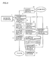
- Fig. 3 shows a system configuration of communication control unit 38 shown in Fig. 2 in accordance with the first embodiment of the present invention.
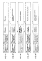
- Figs. 4A to 4E show field configurations of various packets in the first embodiment of the present invention.
- Fig. 4A shows a basic field configuration of a packet.
- Figs. 4B and 4C show inquiry packets
- Figs. 4D and 4E show answer packets.
- the packet includes a transmission source information A1 indicating an electrical equipment as a source of transmission of the packet, transmission destination information A2 indicating an electrical equipment as a transmission destination of the packet, a command A3 and a content A4 related to the command A3.
- Each of the electrical appliances or equipments shown in Fig. 1 has an address for uniquely specifying itself allotted in advance, and in the first embodiment, the address is used for designating the transmission source and destination of the packet.
- the packet of Fig. 4B stores a command for inquiring the function of the electrical equipment and specific content of inquiry, as command A3 and content A4.
- the packet shown in Fig. 4C stores a command inquiring CONTENTS data of the electrical equipment and specific content of the inquiry as command A3 and content A4.
- the data packet shown in Fig. 4D stores a command controlling function implementing unit 98 of the electrical equipment and specific content of control, as command A3 and content A4.
- the packet shown in Fig. 4E stores a command indicating that the packet is an answer packet, and specific content of the answer as command A3 and content A4.
- communication control unit 38 includes a network I/F (hereinafter simply referred to as I/F) 1 for controlling communication between communication control unit 38 and transmission path 37 in relation to I/F 85; a transmission buffer 2 for temporarily storing a packet to be transmitted to other electrical equipment connected to transmission path 37; a reception buffer 3 for temporarily storing a packet received from other electrical equipment connected to transmission path 37; a packet analysis section 4 for analyzing a received packet in reception buffer 3; an address analysis section 5 for comparing transmission destination information of the received packet obtained by the analysis at packet analysis section 4 with self address 71 in address management section 7 which will be described later; a command analysis section 6 for analyzing a command in the received packet obtained by the analysis of the received packet; an address management section 7; an answer packet generating section 8; a function retrieval section 9; a function storage 10; a CONTENTS retrieval section 11; a CONTENTS storage 12; a control packet generating section 13; and a packet generating section 14.
- I/F network I/F
- Transmission buffer 2, reception buffer 3, address management section 7, function storage 10 and CONTENTS storage 12 are provided as regions for storing data on ROM 82, RAM 84 and memory 83 of Fig. 2 .
- Other sections shown in Fig. 3 are stored in advance in ROM 82 as programs and executed under the control of CPU 81, or after the contents of ROM 82 are developed in RAM 84, executed under the control of CPU 81.
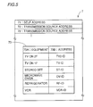
- Fig. 5 shows contents of address management section 7 shown in Fig. 3 .
- Address management section 7 includes a self address 71 allotted in advance for uniquely specifying the electrical equipment itself, a transmission source address 72 which is transmission source information A1 of the received packet, and an address table 73.
- One or more transmission source addresses 72 are stored, and addresses 72 are stored in accordance with the order of reception of packets, respectively.
- addresses 73B corresponding to respective ones of electrical equipments 73A connected to transmission path 37 of Fig. 1 are stored. Addresses 73B correspond to self addresses 71 of respective electrical equipments.
- Fig. 6 shows an example of contents in function storage 10 of Fig. 3 .
- Figs. 7A to 7C show examples of contents of CONTENTS storage 12 shown in Fig. 3 .
- Fig. 8A and 8B show further examples of an answer packet shown in Fig. 4E .
- function storage 10 unique function of an electrical equipment, that is, the function performed by the function unit 98 is stored in the form of information, in advance.
- Fig. 6 shows contents of function storage 10 when the electrical equipment is a videotape recorder with a camera having display function.
- function storage 10 one or more functions B1 and detailed information B2 related to respective functions B1 are stored.
- information indicating "LCD (Liquid Crystal Display)" is stored as detailed information B2 corresponding to the video output function shown in Fig. 6 .
- Function retrieval section 9 retrieves function information stored in function storage 10, in accordance with the content of the received packet.
- CONTENTS storage 12 CONTENTS data held by the electrical equipment is stored in advance.
- the electrical equipment is a VCR
- a genre C1 and a title C2 indicating the recorded content are stored in correspondence to each other in the example shown in Fig. 7A
- time C3 of recording and operation history C4 indicating the channel of the TV designated for recording are stored in correspondence to each other in the example shown in Fig. 7B .
- CONTENTS-data of an equipment such as refrigerator 35 is input by user's manual input or by reading a bar code attached to food, for example.
- Fig. 7C shows an example of CONTENTS storage 12 of refrigerator 35.
- name of food C5 and the data C6 when the food is input to the refrigerator are stored in correspondence to each other.
- CONTENTS retrieval section 11 retrieves CONTENTS data in CONTENTS storage 12 based on the content of the received packet.
- Answer packet generating section 8 generates an answer packet shown in Fig. 4E based on self address 71 stored in address management section 7, transmission source address 72, function information obtained by retrieval by function retrieval section 9 and CONTENTS data obtained by retrieval by CONTENTS retrieval section 11, and stores the packet in transmission buffer 2.
- Control packet generating section 13 generates a control packet shown in Fig. 4D for controlling a desired electric equipment, and stores the generated packet in transmission buffer 2.
- Packet generating section 14 generates an inquiry packet or a control packet such as shown in Fig. 4B or 4C in accordance with the content of instruction applied from function implementing unit 39 through I/F 95, and stores the generated packet in transmission buffer 2.
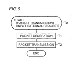
- Fig. 9 is a flow chart showing a packet transmission process in the electronic appliances for home use in accordance with the first embodiment of the present invention.
- a packet is transmitted, first, a user operates input section 96 to input a request and, in response, CPU 91 applies the input request to communication control unit 38 through I/F 95.
- packet generating section 14 of communication control unit 38 When the request is received (T0), packet generating section 14 of communication control unit 38 generates a packet having such a field configuration as shown in Fig. 4A based on the content of request, and stores the generated packet in transmission buffer 2 (T1).
- I/F 1 transmits the packet stored in transmission buffer 2 through transmission path 37.
- Fig. 10 is a flow chart showing packet reception process at each electrical equipment in accordance with the first embodiment of the present invention.
- reception buffer 3 When the packet having such a field configuration as shown in Fig. 4A is received through I/F 1 at each electrical equipment, the received packet is stored in reception buffer 3.
- packet analysis section 4 determines whether or not the packet is a valid packet or not based on header information, not shown, of the received packet in reception buffer 3 (S1). When it is determined that the packet is not a valid packet, the series of processing is completed.
- address analysis section 5 compares the transmission destination address indicated by transmission destination information A2 of the received packet with self address 71 in address management section 7 and determines whether the received packet is addressed to itself. When the addresses match, it means that the received packet is addressed to the equipment itself, and therefore the transmission source address indicated by transmission source information A1 of the received packet is stored as transmission source address 72 in address management section 7 (S2). When the addresses do not match, the processing is completed.
- command analysis section determines whether command A3 of the received packet is a function inquiry command or not (S3).
- function retrieval section 9 retrieves a plurality of functions B1 in function storage 10 based on the content A4 of the received packet, and when a function B1 which corresponds to the inquired function is stored in storage 10, control is passed to answer packet generating section 8 (S4).
- command analysis section 6 determines whether command A3 is a CONTENTS inquiry command or not (S5).
- CONTENTS retrieval section 11 retrieves CONTENTS data in CONTENTS storage 12 based on the content A4 of the received packet. As a result of retrieval, if CONTENTS data which corresponds to the inquired content is found stored in storage 12, the control is passed to answer packet generating section 8.
- command A3 is not a CONTENTS inquiry command (NO in S5)
- the command is applied to I/F 95 of function implementing unit 39, and executed under the control of CPU 91 (S8).
- answer packet generating section 8 generates an answer packet shown in Fig. 4E having self address 71 and transmission source address 72 in address management section 7 as transmission source information A1 and transmission destination information A2, command A3 as a command indicating that it is an answer to an inquiry, content A4 as specific content of answer to the inquiry, and stores the generated packet in transmission buffer 2 (S9).
- I/F 1 transmits the answer packet stored in transmission buffer 2 to transmission path 37.
- answer packet generating section 8 generates the answer packet shown in Fig. 8A when the received packet is the function inquiry packet such as shown in Fig. 4B , and generates an answer packet of Fig. 8B if the received packet is a CONTENTS data inquiry packet such as shown in Fig. 4C .
- the received packet is subjected to process steps S1 to S8 shown in Fig. 10 , applied to function implementing unit 39 from command analysis section 6, and the content of the packet is displayed at output section 97. Therefore, the user can recognize the ID, or address, function and information of CONTENTS of each of the electrical equipments by the display.
- the received packet may be discarded, or an answer packet such as shown in Fig. 4E storing content A4 indicating that the inquired function or CONTENTS is absent, may be transmitted.
- each of the electrical equipments retrieves information related to the function of itself or CONTENTS data stored in itself, and transmits the result of retrieval in the form of an answer packet storing an address specifying the equipment itself, in response to an external inquiry. Therefore, when a function of the electrical equipment or other electrical equipments in the network is to be used, the address of an electrical equipment having the object function or CONTENTS to be controlled can be readily obtained. Therefore, in the network, a table storing addresses of respective electrical equipments and information related to functions of respective electrical equipments in correspondence to each other is unnecessary.
- functions of respective electrical equipments can be shared on the network without the necessity of using a special control apparatus such as a central control unit. Further, function information or CONTENTS data is inquired as needed, and therefore updating of the table at the time of addition or omission of an electrical equipment to and from the network is not necessary.
- Fig. 11 shows a system configuration of communication control unit 38 shown in Fig. 2 in accordance with the second embodiment of the present invention.
- the configuration of Fig. 11 is different from that of Fig. 3 in that address analysis section 5, function retrieval section 9 and CONTENTS retrieval section 11 of Fig. 3 are replaced by address analysis section 5a, function retrieval section 9a and CONTENTS retrieval section 11a as shown in Fig. 11 , so that retrieval of function information and retrieval of CONTENTS data are performed immediately after address analysis of the received packet.
- Other portions of Fig. 11 are common to Fig. 3 , and therefore description thereof is not repeated.
- Fig. 12 is a flow chart of packet reception processing at each of the electrical equipments in accordance with the second embodiment of the present invention.
- Figs. 13A to 13C show control packets and an answer packet in accordance with the second embodiment of the present invention.
- the control packet shown in Fig. 13A stores an address of VCR 36 of Fig. 1 as transmission source information A1, information of the content "equipment having video display function" as transmission destination information A2, "a command for displaying image” as command A3, and image data to be displayed in connection with command A3 as content A4.
- the control packet shown in Fig. 13B stores an address of VCR 36 of Fig.
- the answer packet shown in Fig. 13C stores an address of TV 31 of Fig. 1 as transmission source information A1, an address of VCR 36 as transmission destination information A2, an answer command as command A3, and result of execution of the received command as content A4.
- the answer packet of Fig. 13C is a packet for transmitting result of execution of command A3 in the control packet of Fig. 13A or Fig. 13B .
- control packet shown in Fig. 13A is generated from VCR 36 of Fig. 1 and transmitted to all other electrical equipments through transmission path 37.
- control packet of Fig. 13A is received through I/F 1 and stored in reception buffer 3.
- Packet analysis section 4 determines whether the received packet is a valid packet or not based on header information of the received packet (S11). If it is not a valid packet, the series of processings is completed. When it is a valid packet, address analysis section 5a determines whether transmission destination information A2 of the received packet matches the self address 71 of address management section 7. When the addresses match, the transmission source information A1 of the received packet is stored as transmission source address 72 in address management section 7 (S15), and command A3 is analyzed and executed (S17, S18).
- address analysis section 5a determines whether transmission destination information A2 is indicated by function information or not (S13).
- function retrieval section 9a determines whether the function information indicated by transmission destination information A2 matches with any of the information stored in function storage 10. If the information matches, command A3 is analyzed and executed (S17, S18). If not, the series of processings is completed.
- CONTENTS retrieval section 11a determines whether the information indicated by transmission destination information A2 matches any of the information related to the CONTENTS in CONTENTS storage 12 (S16). When the information matches, command A3 is analyzed and executed (S17, S18). If not, the series of processings is completed.
- command A3 for image display is executed in "equipment having video display function" indicated by transmission destination information A2, that is, TVs 31 and 32 shown in Fig. 1 having the video display function, and image data of content A4 is given on a display of function unit 98, for example.
- the answer packet shown in Fig. 13C may be generated by answer packet generating section 8 to transmit the result of execution of command A3 of the received packet.
- command A3 for transmitting a movie title is executed in "equipment having a movie title" indicated by transmission destination information A2, that is, VCR 36 of Fig. 1 having a movie title as CONTENTS data.
- the answer packet of Fig. 13C storing a movie title in CONTENTS storage 12 as content A4 may be generated and transmitted by answer packet generating section 8.
- the received packet may be discarded.
- an answer packet storing information that the inquired function or CONTENTS data is absent may be transmitted.
- Fig. 14 shows system configuration of communication control unit 38 of Fig. 2 in accordance with the third embodiment.
- the system configuration of Fig. 14 differs from that of Fig. 11 in that answer packet generating section 8 of Fig. 11 is replaced by answer packet generating section 8a, and that an input section 15, an output section 16 and an information identifier storage 17 are added. Except these points, the configuration is the same as that of Fig. 11 , and description thereof is not repeated.
- Information identifier storage 17 stores in advance identifier which can be recognized by the user, such as a character or a numeral for identifying respective ones of the function information and CONTENTS data stored in function storage 10 and CONTENTS storage 12.
- Answer packet generating section 8a stores as content A4, an information identifier in information identifier storage 17 corresponding to the retrieved function information or CONTENTS data in an answer packet, when the answer packet is generated.
- the information identifier may be set in information identifier storage 17 by manual input, or by automatically generating and inputting the identifier from part of the function information and CONTENTS data in function storage 10 and CONTENTS storage 12.
- Input section 15 is for external data input operated by the user, such as a keyboard.
- Output section 16 is for external data output, such as a display.
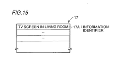
- Fig. 15 shows contents of information identifier storage 17 shown in Fig. 14 .
- Fig. 15 shows an example of information identifier storage 17 of TV 31 shown in Fig. 1 .
- the video output function of TV 31 corresponds to information identifier 17A that "TV screen placed in the living room.”
- Fig. 16 is a flow chart of an answer packet transmission in response to a packet reception in accordance with the third embodiment of the present invention.
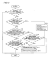
- Fig. 17 is a flow chart of a control packet transmission process in response to a packet reception in accordance with the third embodiment of the present invention.
- Figs. 18A and 18B show examples of an answer packet and a control packet transmitted in accordance with the flow charts of Figs. 16 and 17 .
- VCR 36 generates and transmits an inquiry packet of Fig. 4B to each of the electrical equipments in the system, as in the first embodiment. At this time, each equipment receives and processes the inquiry packet in accordance with the flow chart of Fig. 16 .
- steps S19 to S25 of Fig. 16 are the same as those of steps S1 to S8 of Fig. 10 , and therefore description is not repeated.
- Each equipment generates an answer packet of Fig. 18A at answer packet generating section 8a, when the received inquiry packet is addressed to itself and a function information indicated by content A4 of the inquiry packet is in the function storage 10 (S26).
- Answer packet generating section 8a reads information identifier 17A corresponding to the function information obtained from function storage 10, from information identifier storage 17, and stores the read identifier as content A4 in the answer packet. In this manner, the answer packet of Fig. 18A is generated and transmitted through transmission buffer 2 (S27).
- the answer packet of Fig. 18A storing information identifier 17A in the similar manner is also transmitted from each of the equipments other than TV 31 that has the function information or CONTENTS data matching the inquired content A4. Therefore, VCR 36 receives answer packets from a plurality of equipments.
- information identifier A is extracted by packet analysis section 4 from each of the received answer packets, and the extracted identifier is displayed on output section 16, in VCR 36 (S28, S29).
- the user selects a desired information identifier 17A among the plurality of information identifiers 17A displayed on output section 16, by using input section 15.
- Control packet generating section 13 generates a control packet of Fig. 18B addressed to the equipment which has the selected information identifier 17A, and transmits the control packet through transmission buffer 2 (S30, S31).
- Control packet generating section 13 reads, based on the selected identifier 17A, an address 73B of a corresponding equipment 73A from address table 73 in address management section 7. Based on the read address, the self address 71 and a control command input by the user through input section 15, a control packet of Fig. 18B is generated.
- Fig. 19 shows system configuration of communication control unit 38 shown in Fig. 2 in accordance with the fourth embodiment of the present invention.
- the system configuration of Fig. 19 differs from that of Fig. 14 in that an answer packet generating section 8b is provided in place of answer packet generating section 8a, a control packet generating section 13a and an equipment selecting section 18 are provided in place of control packet generating section 13, input section 15 and output section 16, and an ability level storage 19 is provided in place of information identifier storage 17. Except these points, the configuration of Fig. 19 is the same as that of Fig. 14 , and description thereof is not repeated.
- Fig. 20 shows the content of ability level storage 19 shown in Fig. 19 .
- Ability level storage 19 stores ability level information 19B indicating, by numerical value, for example, how much ability the corresponding equipment has for implementing respective ones of functions 19A.
- ability level information 19b represents relative ability level of the equipments when the function is implemented by respective equipments.
- Answer packet generating section 8b generates an answer packet storing as content A4 the ability level information 19B in ability level storage 19. At this time, the ability level information stored in the answer packet is determined based on the result of retrieval at function retrieval section 9a.
- Function selecting section 18 has a selection reference storage 181 and it compares ability level information 19b of the received packet with a selection reference level stored in advance in storage 181 and selects the equipment as the control packet transmission destination, based on the result of comparison.
- Control packet generating section 13a generates a control packet for controlling the equipment selected by equipment selecting section 18.
- Ability level information 19B in ability level storage 19 may be set by manual input, may be set fixedly equipment by equipment in advance, or may be set when an equipment is connected to the network, and the level, for video output function, for example, may be "5" for a large sized TV and "1" for a small portable TV.
- Fig. 21 is a flow chart of an answer packet transmission in response to a packet reception in accordance with the fourth embodiment of the present invention.
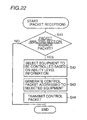
- Fig. 22 is a flow chart of a control packet transmission process in response to a packet reception in accordance with the fourth embodiment of the present invention.
- Figs. 23A and 23B show examples of an inquiry packet and an answer packet processed in accordance with the flow chart of Figs. 21 and 22 .
- VCR 36 generates and transmits an inquiry packet of Fig. 23A to each equipment in the system inquiring "whether the equipment has video output function".
- each equipment receives and processes the inquiry packet in accordance with the flow chart of Fig. 21 .
- the content of processing of steps S32 to S38 of Fig. 21 are the same as those of steps S1 to S8 of Fig. 10 . Therefore, description is not repeated.
- Each equipment generates an answer packet of Fig. 23B at answer packet generating section 8b when the received inquiry packet is addressed to it and function information indicated by content A4 in the inquiry packet is in function information storage 10.
- answer packet generating section 8b generates the answer packet of Fig. 23B storing self address 71 in address management section 7, transmission source address 72, and ability level information 19B corresponding to the inquired function 19A in ability level storage 19 as transmission source information A1, transmission destination information A2 and content A4, respectively (S39).
- the generated answer packet is transmitted through transmission buffer 2 (S40).
- VCR 36 As it transmitted the inquiry packet of Fig. 23A , it receives answer packet of Fig. 23B .
- answer packet of Fig. 23B Referring to Fig. 22 , in packet analysis section 4, ability level information 19B is extracted from the received answer packet and the extracted information is applied to equipment selecting section 18 (S41).
- equipment selecting section 18 based on the applied ability level information 19B and selection reference of selection reference storage 181, whether or not the equipment of the answer packet transmission source is to be selected as the object equipment of control.
- a plurality of answer packets are received and a plurality of pieces of ability level information 19B are obtained, for example, an equipment having the highest level of video output function is selected as the object of control, provided that the selection reference is set to select an equipment of highest ability level (S42).
- Selecting section 18 designates which equipment corresponding to which answer packet received at what order is selected. Accordingly, control packet generating section 13a reads the corresponding transmission source address 72 and self address 71 to that answer packet which is designated by address management section 7, and generates a control packet of Fig. 4D using these read addresses and a control command which has been set or applied in advance (S43).
- the generated control packet is stored in transmission buffer 2, and thereafter transmitted through I/F 1 (S44). Therefore, in the selected equipment, the control packet is received, and process in accordance with the content of the received packet is performed.
- an equipment suitable for realizing the inquired function is automatically selected.
- Fig. 24 shows system configuration of communication control unit 38 of Fig. 2 in accordance with the fifth embodiment of the present invention.
- Fig. 24 The system configuration of Fig. 24 is different from that of Fig. 19 in that an answer packet generating section 8c, a control packet generating section 13b and an equipment selecting section 18a are provided in place of answer packet generating section 8b, control packet generating section 13a and equipment selecting section 18, and that a priority setting section 20 and a priority storage 21 are provided in place of ability level storage 19.
- Other portions of Fig. 24 are the same as those of Fig. 19 , and description thereof is not repeated.
- priority of equipment executing a function is set in advance in priority setting section 20 and stored in priority storage 21, function by function.
- answer packet generating section 8c an answer packet storing priority information in priority storage 21 is generated.
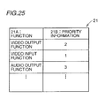
- Fig. 25 shows contents of priority storage 21 of Fig. 24 .
- priority information 21B is stored indicating, in numerical value, for example, priority of implementation of each equipment for respective functions 21A.
- priority information of video output function is set by priority setting section 20 in advance, such that TV 31 placed in the living room shown in Fig. 1 has the priority of "1" and TV 32 placed in a room in the second floor has the priority of "2".
- priority information 21B of implementing the function is set equipment by equipment and stored in priority storage 21. The priority may be determined arbitrarily by manual input, or it may be determined in accordance with the installed place of the equipment.
- the ability level information represents ability of each equipment to implement a function.
- the priority of the present invention is different.
- the priority indicates the equipment which is used with priority when the function is to be implemented. Therefore, both ability level information and priority information may be provided and ability level information and priority information may be used appropriately in accordance with the operation performed by implementation of a function or in accordance with the state or time of use.
- Answer packet generating section 8c generates an answer packet storing as content A4, priority information 21B of priority storage 21. At this time, the stored priority information 21B is determined based on the result of retrieval by function retrieval section 9a.
- Equipment selecting section 18a has selection reference storage 182, and compares priority information 21B of the received packet with the selection reference level stored in advance in storage 182. Based on the result of comparison, the selecting section 18a selects an equipment of control packet transmission destination, and applies the result of selection to control packet generating section 13b.
- Control packet generating section 13b generates a control packet for controlling the equipment selected based on the applied result of selection.
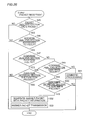
- Fig. 26 is a flow chart of an answer packet transmission in response to a packet reception in accordance with the fifth embodiment of the present invention.
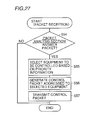
- Fig. 27 is a flow chart of a control packet transmission process in response to a packet reception in accordance with the fifth embodiment of the present invention.
- Figs. 28A and 28B show examples of an inquiry packet and an answer packet processed in accordance with the process flow chart of Figs. 26 and 27 .
- VCR 36 generates and transmits an inquiry packet of Fig. 28A to each of the equipments in the system, the packet storing, as content A4, "whether the equipment has video output function".
- each equipment processes the inquiry packet of 28A in accordance with the flow chart of Fig. 26 .
- the processes in steps S45 to S51 of Fig. 26 are the same as those of steps S1 to S8 of Fig. 10 . Therefore, description thereof is not repeated.
- answer packet generating section 8c generates an answer packet of Fig. 28B in the following manner, when the received inquiry packet is addressed to it and function information indicated by content A4 in the inquiry packet is present in the function storage 10.
- answer packet generating section 8c generates an answer packet of Fig. 28B storing self address 71 in address management section 7, transmission source address 72 and priority information 21B corresponding to the inquired function 21A in priority storage 21 as transmission source information A1, transmission destination information A2 and content A4, respectively (S52).
- the generated answer packet is transmitted through transmission buffer 2 (S53).
- priority information 21B is extracted from each of the successively received answer packets of Fig. 28B , and the extracted information is applied to equipment selecting section 18a (S54).
- Control packet generating section 13b transmits a control packet of Fig. 4D , for example, by reading corresponding transmission source address 72 from address management section 7 and using predetermined control command, read transmission source address 72 and so on based on the result of selection, and stores the packet in transmission buffer 2 (S56).
- the control packet stored in transmission buffer 2 is transmitted through I/F 1 (S57). Therefore, in the equipment selected by priority information 21B, the control packet is received, and process in accordance with the content of the received control packet is performed.
- each equipment has priority information 21B.
- any one of the equipments in the network may have priority information 21B of all the equipments and priority may be inquired of that equipment.
- each equipment may have priority information 21B of all the equipments.
- an equipment to be the object of control can be selected automatically in accordance with the priority information 21B.
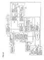
- Fig. 29 shows system configuration of communication control unit 38 of Fig. 2 in accordance with the sixth embodiment of the present invention.
- Fig. 29 The system configuration of Fig. 29 is different from that of Fig. 24 in that an answer packet generating section 8d is provided in place of answer packet generating section 8c, and that a busy state determining section 22, a busy factor storage 23 and a busy packet generating section 24 are provided in place of priority storage 21, priority setting section 20, equipment selecting section 18a and control packet generating section 13b.
- Other portions of Fig. 29 are the same as those of Fig. 24 , and therefore description thereof is not repeated.
- Fig. 30 shows contents of busy factor storage 23 of Fig. 29 .
- Busy data BD indicates uniquely a function which is being processed (implemented) in function implementing unit 39, in the form of a numerical value, for example.
- Busy factor storage 23 has a plurality of busy factors 23A stored in advance as shown in Fig. 30 , and it is accessed based on busy data BD. Therefore, details of the function which is being implemented indicated by busy data BD are given in detail in busy factor 23A corresponding to data BD.
- busy state refers to a state in which a function is being implemented or carried out in function implementing unit 39 of an equipment and therefore other function cannot be implemented.
- Busy data BD refers to data indicating uniquely the function which is the cause of the busy state and it assumes a value "0", for example, when it is not a busy state.
- Busy packet generating section 24 generates a busy packet, which is an answer packet, when it is determined by busy state determination section 22 that the corresponding function implementing unit 39 is in a busy state.
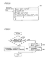
- Fig. 31 is a flow chart of processing in response to reception of a control packet in accordance with the sixth embodiment of the present invention.
- Figs. 32A and 32B show examples of a control packet and an answer packet processed in accordance with the flow chart of Fig. 31 .
- the user operates input section 96 of VCR 36 and inputs a request for displaying image data recorded by function unit 98 on TV 31 in the living room on the first floor.
- control packet of Fig. 32A is generated by packet generating section 14 and transmitted.
- TV 31 processes command at command analysis section 6 in accordance with the processes of steps S1 to S7 of the flow chart similar to those of Fig. 10 (S8).
- Command analysis section 6 interprets that the command in the control packet as a command for displaying image data, and passes control to busy state determination section 22.
- busy state determining section 22 determines whether or not the corresponding function implementing unit 39 is in the busy state, based on applied busy data BD (S58).
- command processing is requested of command analysis section 6 and, by answer packet generating section 8d, an answer packet such as shown in Fig. 13C storing the result of command execution is generated and transmitted (S59).
- busy packet generating section 24 When it is determined that the corresponding function unit 98 is in the busy state as a TV broadcast image is being displayed, for example, busy packet generating section 24 generates a busy packet shown in Fig. 32B by using busy factor 23A obtained by accessing to busy factor storage 23 based on busy data BD, self address 71 and transmission source address 72 obtained with reference to address management section 7 (S60).
- the generated busy packet is stored in transmission buffer 2 and transmitted (S61).
- a busy packet storing the busy factor 32A is transmitted. Therefore, it can be readily determined by the equipment on the controlling side whether the equipment to be controlled does not have the desired function or the equipment to be controlled cannot perform the desired function simply because it is busy. Further the controlling equipment receives busy factor 32A, and therefore it can recognize why the desired function cannot be executed.
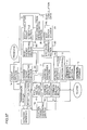
- Fig. 33 shows system configuration of communication control unit 38 of Fig. 2 in accordance with the seventh embodiment of the present invention.
- Fig. 33 The system configuration of Fig. 33 is different from that of Fig. 29 in that an output section 15a for outputting various data, in the form of a display device, for example, an input section 16a for inputting various data and operated by the user, an interruption packet generating section 25 and an interruption executing section 26 are added.
- Other portions of Fig. 33 are the same as those of Fig. 29 , and therefore description thereof is not repeated.
- Interruption packet generating section 25 generates an interruption packet in response to an interruption request input through input section 16a, and stores the generated packet in transmission buffer 2.
- interruption executing section 26 applies a command in the interruption packet to function implementing unit 39 which is in the busy state, through I/F 95. Accordingly, the command is interpreted by CPU 91 in function implementing unit 39, the process which is being carried out by function unit 98 is interrupted and stopped, and new process based on the result of interpretation is started in function implementing unit 39.
- Fig. 34 is a flow chart of a process in response to a busy packet reception in accordance with the seventh embodiment of the present invention.
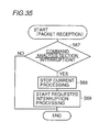
- Fig. 35 is a flow chart of a process in response to an interruption packet reception in accordance with the seventh embodiment of the present invention.
- Fig. 36 is shows an example of an interruption packet in accordance with the seventh embodiment of the present invention.
- the busy packet shown in Fig. 32B generated and transmitted in accordance with the sixth embodiment above is received by VCR 36, subjected to processes of steps S1 to S3 and S5 of Fig. 10 .
- Command analysis section 6 of VCR 36 interprets answer command A3 and content A4 (busy factor 23A) of the received busy packet, and as it is a busy packet, applies the busy factor 23A to output section 15a (S62).
- interruption packet generating section 25 In response to the interruption request from input section 16a, interruption packet generating section 25 reads from address management section 7 self address 71 and transmission source address 72 corresponding to the designated data of the input busy factor, and generates an interruption packet of Fig. 36 based on the read addresses 71 and 72 as well as the input command (S65). The generated interruption packet is stored in transmission buffer 2 and thereafter transmitted (S66).
- the interruption packet of Fig. 36 stores image data as content A4.
- the image data is input from a corresponding function implementing unit 39 through I/F 95.
- Command analysis section 6 determines that command A3 of the interruption packet includes an interruption command (S67). Therefore, in accordance with the result of determination, interruption executing section 26 applies an instruction to function implementing unit 39 through I/F 95 to start a new process in accordance with command A3 and content A4, by interrupting the process which is being carried out in function section 98 (S68).
- CPU 91 interrupts the process which is being carried out or implemented in function unit 98 in response to the applied instruction, and starts new process in accordance with command A3 and content A4 (S69).
- the TV broadcast display is forcefully interrupted, and display of image data in the interruption packet starts.
- the seventh embodiment it is possible to interrupt and stop a process which is being executed in an equipment which is an object of control in accordance with the user's request and to execute with priority a new process desired by the user, by transmission/reception of an interruption packet between each of the equipments.
- Fig. 37 shows system configuration of communication control unit 38 of Fig. 2 in accordance with the eighth embodiment of the present invention.
- Fig. 37 differs from that of Fig. 29 in that a control packet generating section 13c for generating a control packet, a busy cancellation packet generating section 27 and a busy cancellation determination section 28 are added. Other portions of Fig. 37 are the same as those of Fig. 27 , and therefore description thereof is not repeated.
- Busy cancellation determination section 28 determines whether or not the busy state is canceled, based on busy cancellation data BR applied from function implementing unit 39 through I/F 95.
- CPU 91 in function implementing unit 39 monitors the state of function section 98 and when it determines that the busy state is canceled, it outputs in response busy cancellation data BR to busy cancellation determination section 28 in communication control unit 38 through I/F 95.
- Busy cancellation packet generating section 27 generates a busy cancellation packet in response to determination by busy cancellation determination section 28 that the busy state is canceled, and stores the generated packet in transmission buffer 2.
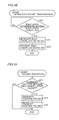
- Fig. 38 is a flow chart related to determination of busy state cancellation after transmission of a busy packet in each equipment in accordance with the eighth embodiment of the present invention.
- Fig. 39 is a flow chart showing a process in response to reception of a busy cancellation packet in each equipment in accordance with the eighth embodiment of the present invention.
- Fig. 40 shows an example of the busy cancellation packet in accordance with the eighth embodiment of the present invention.
- a busy packet when a busy packet is received in TV 31, for example, whether the busy state is canceled or not is determined in accordance with whether busy cancellation data BR is applied or not, at the corresponding function implementing unit 39 by busy cancellation determining section 28 (S70). If it is determined that the busy state is canceled, busy cancellation packet generating section 27 generates a busy cancellation packet shown in Fig. 40 in response (S71). The busy cancellation packet of Fig. 40 stores a busy cancellation command indicating that the busy state is canceled, as command A3.
- the generated busy cancellation packet is transmitted to VCR 36 which has transmitted the busy packet, through transmission buffer 2 (S72).
- VCR 36 receives the busy cancellation packet transmitted from TV 31 through reception buffer 3.
- the received busy cancellation packet is subjected to processes of steps S1 to S3 and S5 of Fig. 10 , and command analysis section 6 determines that command A3 in the received packet is a busy cancellation command (S73).
- control packet generating section 13c generates a control packet addressed to TV 31 which stores a control command applied in advance (S74).
- the generated control packet is transmitted through transmission buffer 2 and received by TV 31 (S75).
- the equipment when an equipment receiving a control instruction from a control packet from another equipment is in the busy state and thereafter the busy state is canceled, the equipment transmits to said another equipment the busy cancellation packet. Therefore, state of other equipment can readily be known without the necessity of transmission process to know whether other equipments are in the busy state or not, such as the process of transmitting the same control packet repeatedly to other equipments.
- each equipment is described as having functions of transmitting, receiving and processing and inquiry packet, transmitting, receiving and processing an answer packet, and transmitting, receiving and processing a control packet.
- the description is not limiting. More specifically, the plurality of equiments connected to transmission path 37 may include an equipment having only a function of transmitting a packet and receiving an answer packet in response, or an equipment having only a function of receiving an inquiry packet and transmitting an answer packet in response.
Landscapes
- Engineering & Computer Science (AREA)
- Automation & Control Theory (AREA)
- Computer Networks & Wireless Communication (AREA)
- Signal Processing (AREA)
- Computer Security & Cryptography (AREA)
- Data Exchanges In Wide-Area Networks (AREA)
- Small-Scale Networks (AREA)
- Communication Control (AREA)
- Selective Calling Equipment (AREA)
Applications Claiming Priority (3)
| Application Number | Priority Date | Filing Date | Title |
|---|---|---|---|
| JP271997 | 1997-01-10 | ||
| JP33165497A JP3586548B2 (ja) | 1997-01-10 | 1997-12-02 | 通信方法、通信システム、通信プログラムを記録したコンピュータで読取可能な記録媒体および通信機器 |
| EP97123048A EP0853401B1 (fr) | 1997-01-10 | 1997-12-31 | Méthode et système de communication |
Related Parent Applications (1)
| Application Number | Title | Priority Date | Filing Date |
|---|---|---|---|
| EP97123048A Division EP0853401B1 (fr) | 1997-01-10 | 1997-12-31 | Méthode et système de communication |
Publications (1)
| Publication Number | Publication Date |
|---|---|
| EP1993236A1 true EP1993236A1 (fr) | 2008-11-19 |
Family
ID=26336178
Family Applications (2)
| Application Number | Title | Priority Date | Filing Date |
|---|---|---|---|
| EP97123048A Expired - Lifetime EP0853401B1 (fr) | 1997-01-10 | 1997-12-31 | Méthode et système de communication |
| EP08014913A Withdrawn EP1993236A1 (fr) | 1997-01-10 | 1997-12-31 | Système et procédé de communication |
Family Applications Before (1)
| Application Number | Title | Priority Date | Filing Date |
|---|---|---|---|
| EP97123048A Expired - Lifetime EP0853401B1 (fr) | 1997-01-10 | 1997-12-31 | Méthode et système de communication |
Country Status (4)
| Country | Link |
|---|---|
| US (1) | US6167046A (fr) |
| EP (2) | EP0853401B1 (fr) |
| JP (1) | JP3586548B2 (fr) |
| DE (1) | DE69738954D1 (fr) |
Families Citing this family (26)
| Publication number | Priority date | Publication date | Assignee | Title |
|---|---|---|---|---|
| US20030179719A1 (en) * | 1998-05-22 | 2003-09-25 | Takashi Kobayashi | Method and apparatus for transmitting packets at a transfer rate that depends on a response from a destination |
| US6559882B1 (en) * | 1999-09-02 | 2003-05-06 | Ncr Corporation | Domestic appliance |
| JP3823585B2 (ja) * | 1999-02-22 | 2006-09-20 | 株式会社日立製作所 | 機器ネットワーク接続方法およびルータ機器 |
| JP2001086572A (ja) * | 1999-07-13 | 2001-03-30 | Matsushita Electric Ind Co Ltd | 家電機器制御ネットワークシステム |
| KR20010072901A (ko) | 1999-07-13 | 2001-07-31 | 모리시타 요이찌 | 가전기기 제어네트워크시스템 |
| KR100620186B1 (ko) | 1999-09-21 | 2006-09-01 | 엘지전자 주식회사 | 디지털 인터페이스에서의 명령 및 응답 프레임 생성장치 및 방법 |
| US7026949B2 (en) * | 2001-05-02 | 2006-04-11 | Lg Electronics Inc. | Method for transmitting and receiving messages in home appliance networking system |
| KR100434270B1 (ko) * | 2001-05-30 | 2004-06-04 | 엘지전자 주식회사 | 가전기기 네트워크 제어시스템 |
| JP2003110961A (ja) * | 2001-09-27 | 2003-04-11 | Sony Corp | 映像表示制御方法及び映像機器 |
| US7933945B2 (en) | 2002-06-27 | 2011-04-26 | Openpeak Inc. | Method, system, and computer program product for managing controlled residential or non-residential environments |
| US6792323B2 (en) | 2002-06-27 | 2004-09-14 | Openpeak Inc. | Method, system, and computer program product for managing controlled residential or non-residential environments |
| US8116889B2 (en) | 2002-06-27 | 2012-02-14 | Openpeak Inc. | Method, system, and computer program product for managing controlled residential or non-residential environments |
| US7024256B2 (en) * | 2002-06-27 | 2006-04-04 | Openpeak Inc. | Method, system, and computer program product for automatically managing components within a controlled environment |
| JP4852226B2 (ja) * | 2002-12-27 | 2012-01-11 | セイコーエプソン株式会社 | デバイス監視システム |
| US7987489B2 (en) | 2003-01-07 | 2011-07-26 | Openpeak Inc. | Legacy device bridge for residential or non-residential networks |
| KR100474930B1 (ko) * | 2003-02-17 | 2005-03-10 | 엘지전자 주식회사 | 홈 네트워크 제품군의 히스토리 모니터링 장치 및 방법 |
| US7668990B2 (en) | 2003-03-14 | 2010-02-23 | Openpeak Inc. | Method of controlling a device to perform an activity-based or an experience-based operation |
| US8042049B2 (en) | 2003-11-03 | 2011-10-18 | Openpeak Inc. | User interface for multi-device control |
| JP4551724B2 (ja) * | 2003-09-30 | 2010-09-29 | キヤノン株式会社 | 放送受信装置、放送受信システム、放送受信装置の制御方法、及び放送受信方法 |
| US7196625B1 (en) | 2003-10-27 | 2007-03-27 | Nguyen Thu H | Advanced food and/or drink organization and/or handling system |
| KR100636784B1 (ko) | 2005-02-22 | 2006-10-20 | 삼성전자주식회사 | 홈네트워크의 서비스 프레임워크 |
| US7907054B1 (en) | 2006-06-05 | 2011-03-15 | Nguyen Thu H | Advanced food and/or drink organization and/or handling system |
| WO2008046141A1 (fr) * | 2006-10-17 | 2008-04-24 | Avega Systems Pty Ltd | Unification de dispositifs multimédia |
| JP4743305B2 (ja) * | 2009-01-06 | 2011-08-10 | ソニー株式会社 | 境界定義による機能制御方法、境界定義による機能制御システム、境界定義による機能制御サーバ及びプログラム |
| JP2013247580A (ja) * | 2012-05-28 | 2013-12-09 | Funai Electric Co Ltd | 電子機器、電子機器システム、及び電子機器制御方法 |
| CN103916781A (zh) * | 2012-12-31 | 2014-07-09 | 广州励丰文化科技股份有限公司 | 高保真有源扬声器的遥控方法 |
Citations (5)
| Publication number | Priority date | Publication date | Assignee | Title |
|---|---|---|---|---|
| JPS59174049A (ja) * | 1983-03-24 | 1984-10-02 | Fujitsu Ltd | アドレスコンパレ−タ診断方式 |
| US5086385A (en) * | 1989-01-31 | 1992-02-04 | Custom Command Systems | Expandable home automation system |
| EP0610630A2 (fr) * | 1992-12-21 | 1994-08-17 | Sony Corporation | Bus bidirectionel et méthodes d'émission, de réception et de communication associées |
| JPH0819060A (ja) | 1994-06-29 | 1996-01-19 | Mitsubishi Electric Corp | Av機器制御システム |
| US5570085A (en) | 1989-06-02 | 1996-10-29 | Ludo A. Bertsch | Programmable distributed appliance control system |
Family Cites Families (6)
| Publication number | Priority date | Publication date | Assignee | Title |
|---|---|---|---|---|
| US4969147A (en) * | 1987-11-10 | 1990-11-06 | Echelon Systems Corporation | Network and intelligent cell for providing sensing, bidirectional communications and control |
| US5341499A (en) * | 1992-04-02 | 1994-08-23 | International Business Machines Corporation | Method and apparatus for processing multiple file system server requests in a data processing network |
| US5467263A (en) * | 1992-06-10 | 1995-11-14 | Euro Cp S.A.R.L. | Process for designating a distant functional object in a circuit, and functional units and installation pertaining thereto |
| US5870554A (en) * | 1996-04-01 | 1999-02-09 | Advanced Micro Devices, Inc. | Server selection method where a client selects a server according to address, operating system and found frame for remote booting |
| GB9623298D0 (en) * | 1996-11-08 | 1997-01-08 | Int Computers Ltd | Updating mechanism for software |
| US5950010A (en) * | 1996-11-25 | 1999-09-07 | J.D. Edwards World Source Co. | System and method for customized application package building and installation |
-
1997
- 1997-12-02 JP JP33165497A patent/JP3586548B2/ja not_active Expired - Fee Related
- 1997-12-31 EP EP97123048A patent/EP0853401B1/fr not_active Expired - Lifetime
- 1997-12-31 EP EP08014913A patent/EP1993236A1/fr not_active Withdrawn
- 1997-12-31 DE DE69738954T patent/DE69738954D1/de not_active Expired - Lifetime
-
1998
- 1998-01-09 US US09/004,861 patent/US6167046A/en not_active Expired - Lifetime
Patent Citations (5)
| Publication number | Priority date | Publication date | Assignee | Title |
|---|---|---|---|---|
| JPS59174049A (ja) * | 1983-03-24 | 1984-10-02 | Fujitsu Ltd | アドレスコンパレ−タ診断方式 |
| US5086385A (en) * | 1989-01-31 | 1992-02-04 | Custom Command Systems | Expandable home automation system |
| US5570085A (en) | 1989-06-02 | 1996-10-29 | Ludo A. Bertsch | Programmable distributed appliance control system |
| EP0610630A2 (fr) * | 1992-12-21 | 1994-08-17 | Sony Corporation | Bus bidirectionel et méthodes d'émission, de réception et de communication associées |
| JPH0819060A (ja) | 1994-06-29 | 1996-01-19 | Mitsubishi Electric Corp | Av機器制御システム |
Also Published As
| Publication number | Publication date |
|---|---|
| DE69738954D1 (de) | 2008-10-16 |
| EP0853401B1 (fr) | 2008-09-03 |
| JP3586548B2 (ja) | 2004-11-10 |
| EP0853401A2 (fr) | 1998-07-15 |
| JPH10257075A (ja) | 1998-09-25 |
| US6167046A (en) | 2000-12-26 |
| EP0853401A3 (fr) | 1999-12-01 |
Similar Documents
| Publication | Publication Date | Title |
|---|---|---|
| EP0853401B1 (fr) | Méthode et système de communication | |
| EP0718786B1 (fr) | Systeme de service d'information et terminal utilisateur | |
| US7376590B2 (en) | Union remote controller, union remote controller information providing system and method for using the same | |
| US6844807B2 (en) | Home electronics system enabling display of state of controlled devices in various manners | |
| JP4891525B2 (ja) | 双方向テレビジョン用の個人チャンネルを効果的に実施するシステム及びその実施方法 | |
| US20030100962A1 (en) | Appliance control system and method using mobile communications terminal, and home gateway | |
| US6856346B1 (en) | Camera operation apparatus | |
| US20030070168A1 (en) | Method and apparatus for editing an electronic program guide | |
| US20030038730A1 (en) | Apparatus and system for controlling appliances | |
| US20040150546A1 (en) | Remote control service processing device using GUI in home network environment | |
| US20110077751A1 (en) | Systems and methods for controlling appliances via a network | |
| US20020073161A1 (en) | Work flow system and client in work flow system | |
| US7890610B2 (en) | Information processing apparatus, network system and network system control method | |
| KR20040005598A (ko) | 가정 전화 제품의 제어 장치, 제어 방법, 제어 프로그램및 가정 전화 제품 | |
| EP1634184A1 (fr) | Systeme permettant le telechargement de contenus par l'intermediaire dun reseau | |
| WO2001099410A2 (fr) | Personnalisation, a base de jetons, d'appareils intelligents | |
| KR20010085438A (ko) | 정보처리장치 및 방법, 네트워크 시스템, 기록매체와프로그램 | |
| MX2007016356A (es) | Metodo y sistema para proveer servicio de transferencia continua en red domestica. | |
| JP2002009807A (ja) | ネットワークサーバおよびネットワークシステム | |
| US20040088364A1 (en) | Apparatus and method for controlling electronic devices | |
| JP2003316676A (ja) | 機器及びネットワークシステム | |
| KR20150110877A (ko) | 사용자 기반 홈 오토메이션 수행 방법 및 장치와 이를 지원하는 방법 및 장치 | |
| EP1006419A1 (fr) | Appareil, méthode et programme pour ajuster le niveau d'automatisation | |
| JPH10198734A (ja) | ネットワーク用家電機器およびネットワークシステム | |
| JP2002007240A (ja) | 情報処理装置、電化製品管理システム及び情報制御方法 |
Legal Events
| Date | Code | Title | Description |
|---|---|---|---|
| PUAI | Public reference made under article 153(3) epc to a published international application that has entered the european phase |
Free format text: ORIGINAL CODE: 0009012 |
|
| AC | Divisional application: reference to earlier application |
Ref document number: 0853401 Country of ref document: EP Kind code of ref document: P |
|
| AK | Designated contracting states |
Kind code of ref document: A1 Designated state(s): DE FR GB |
|
| RIN1 | Information on inventor provided before grant (corrected) |
Inventor name: WAKAI, HIROHISA Inventor name: NISHIMURA, TAKASHI Inventor name: TERADA, SATOSHI Inventor name: UEDA, TORU |
|
| RIN1 | Information on inventor provided before grant (corrected) |
Inventor name: NISHIMURA, TAKASHI Inventor name: WAKAI, HIROHISA Inventor name: UEDA, TORU Inventor name: TERADA, SATOSHI |
|
| 17P | Request for examination filed |
Effective date: 20090519 |
|
| AKX | Designation fees paid |
Designated state(s): DE FR GB |
|
| 17Q | First examination report despatched |
Effective date: 20100426 |
|
| STAA | Information on the status of an ep patent application or granted ep patent |
Free format text: STATUS: THE APPLICATION IS DEEMED TO BE WITHDRAWN |
|
| 18D | Application deemed to be withdrawn |
Effective date: 20130222 |