EP1992775A2 - Profiled connection strip, inparticular profiled connection strip for a reveal - Google Patents
Profiled connection strip, inparticular profiled connection strip for a reveal Download PDFInfo
- Publication number
- EP1992775A2 EP1992775A2 EP08007999A EP08007999A EP1992775A2 EP 1992775 A2 EP1992775 A2 EP 1992775A2 EP 08007999 A EP08007999 A EP 08007999A EP 08007999 A EP08007999 A EP 08007999A EP 1992775 A2 EP1992775 A2 EP 1992775A2
- Authority
- EP
- European Patent Office
- Prior art keywords
- web
- outer leg
- profile strip
- adhesive
- plaster
- Prior art date
- Legal status (The legal status is an assumption and is not a legal conclusion. Google has not performed a legal analysis and makes no representation as to the accuracy of the status listed.)
- Withdrawn
Links
Images


Classifications
-
- E—FIXED CONSTRUCTIONS
- E06—DOORS, WINDOWS, SHUTTERS, OR ROLLER BLINDS IN GENERAL; LADDERS
- E06B—FIXED OR MOVABLE CLOSURES FOR OPENINGS IN BUILDINGS, VEHICLES, FENCES OR LIKE ENCLOSURES IN GENERAL, e.g. DOORS, WINDOWS, BLINDS, GATES
- E06B1/00—Border constructions of openings in walls, floors, or ceilings; Frames to be rigidly mounted in such openings
- E06B1/62—Tightening or covering joints between the border of openings and the frame or between contiguous frames
- E06B1/68—Tightening or covering joints between the border of openings and the frame or between contiguous frames by profiled external parts
-
- E—FIXED CONSTRUCTIONS
- E06—DOORS, WINDOWS, SHUTTERS, OR ROLLER BLINDS IN GENERAL; LADDERS
- E06B—FIXED OR MOVABLE CLOSURES FOR OPENINGS IN BUILDINGS, VEHICLES, FENCES OR LIKE ENCLOSURES IN GENERAL, e.g. DOORS, WINDOWS, BLINDS, GATES
- E06B1/00—Border constructions of openings in walls, floors, or ceilings; Frames to be rigidly mounted in such openings
- E06B1/62—Tightening or covering joints between the border of openings and the frame or between contiguous frames
- E06B2001/624—Tightening or covering joints between the border of openings and the frame or between contiguous frames with parts to be embedded in the stucco layer or otherwise linked to this layer
Definitions
- connection profile strip in particular soffit connection profile strip
- a profile body with an outer leg and with this via connecting webs movably connected frame mounting portion for attaching the bar to a frame or rail component, in particular a door or window frame or a roller blind rail, via an adhesive surface
- said the profiled body is provided at least partially, preferably completely concealing, facing web in the assembly position outer connecting web.
- Such moldings are usually used to produce a transition between a window or door frame or a roller blind rail and an adjoining wall, with known connection profiles either connect to a plaster layer, or serve the inclusion of cladding panels or the like.
- known strips is sometimes a relative mobility of the component mounting portion, so the profile body part, which is attached via the adhesive surface on the frame or the rail to the outer leg, are provided on the example projecting webs or the like, realized via connecting webs, the outer leg and the component mounting portion connect, and which consist of a softer material than the outer leg and the component mounting portion, such as soft PVC, while the other profile body parts made of rigid PVC.
- This relative mobility makes it possible, to a certain extent, to be able to compensate for any movements that occur over time between the frame or rail component and the plaster surface in which the outer leg is anchored and at the same time maintain the connection and sealing realized via the strip hold.
- a substantially vertically projecting from this side web is provided on the outer leg, to which after the application of the plaster layer on the adjacent masonry or the like. the plaster layer connects.
- the bridge is thus visible in the mounting position, it forms a clean connection to the plaster layer.
- the region below the outer leg with the connecting webs and the component fastening section remains optically visible as well comprising, for example, the relatively thick foam adhesive tape.
- a side-projecting sealing lip is formed on the attachment portion, which covers the foam adhesive tape, so that in this case this sealing lip would be visible. The visibility of this area is therefore sometimes not appealing for visual reasons.
- connection profile strip which can be processed visually appealing.
- connection profile of the aforementioned type that on the profile body in the mounting position outer Einputzsteg, which preferably protrudes vertically from the outer leg, is provided, which is formed extended to form the fairing web, the outside of the Einputzstegs and the cladding web is provided with a covering which improves the adhesion of a plaster or paint layer to be applied or with an adhesion-improving three-dimensional surface structure.
- This fairing web which is preferably arranged close to or at the edge of the outer leg, thus extends to some extent laterally of the intended connecting webs and optionally of the foam adhesive tape, so at least partially covers the area located below the outer web. It remains in the mounting position thus a shadow gap to the frame member, which is more or less wide, depending on how far the fairlead is pulled.
- the final joint width is ultimately dependent on the specific design of the profile strip, in particular the actual size or the profile body structure.
- an outer Einputzsteg which preferably protrudes vertically from the outer web, formed extended to form the fairing web.
- This web which connects to the plaster layer as described in the assembly position, is now according to the invention extended downwards, so that the cladding web is formed in the immediate extension.
- the assembly position so that a uniform surface is given, it remains only the narrowest possible shadow gap, from the lying below the outer leg area is no longer visible. This results in a very attractive, homogeneous appearance.
- the exterior in the mounting position Einputzsteg on its outside with a the adhesion of a applied plaster or paint layer improving coating or serving for this surface structure, eg. B. is provided a roughening. It is a Einputzsteg provided, which is so even plastered, so in the mounting position is under plaster. It therefore serves as a plaster or color carrier, that is, it is completely plastered or painted on the outside, so that it is not visible in the mounting position.
- the outside of the plasterboard is provided with a corresponding adhesion-improving coating or structured three-dimensional.
- the cover web provided according to the invention can also be concealed in an optically appealing manner if, as is furthermore provided according to the invention, the cover web also bears the adhesion of the plaster surface to be applied. or color layer improving coating or such an adhesive structure is provided.
- the cover web also bears the adhesion of the plaster surface to be applied. or color layer improving coating or such an adhesive structure is provided.
- the Einputzsteg is extended and merges directly into the panel web, it is easily possible to apply the adhesion-improving coating on the entire profile body outside, formed by the outside of the Einputzsteges and the fairing web, or to provide said side with the structuring.
- the profile strip is then completely gone under plaster or paint, it is only the shadow gap to see.
- the excellent properties of the strip according to the invention with regard to the absorption of longitudinal and transverse forces due to the working structure are retained.
- the pad may be a preferably glued structured band, z.
- a plastic or textile tape or a glued fabric (eg., A glass fiber fabric) or on the type of flocking applied fibers, each in particular of plastic or textile, be.
- a surface structuring is achieved, which makes it possible that in particular the plaster layer can dig into the surface structure.
- the tape or fabric or flakes may be plastic.
- a perforated or otherwise three-dimensionally deformed plastic tape, optionally provided on the back with a self-adhesive layer, are glued.
- the fabric can be, for example, a textile fabric made of synthetic fibers which, for example, is woven very coarsely or consists of thick fibers, so that a corresponding "open-pored" weave structure results.
- synthetic fibers for “flocking” preferably plastic fibers of one or more millimeters in length can be used, which are applied for example to a previously applied adhesive layer, or which are optionally contained in a curing or self-adhesive support material, which is applied to the outside of the Einputzsteges and optionally the panel web ,
- the fibers embedded in the carrier mass protrude from this, thus forming a three-dimensionally structured surface when the carrier material, for example a curing adhesive or synthetic resin, has hardened.
- the carrier material for example a curing adhesive or synthetic resin
- the coating may also be an adhesive or cured carrier medium with particles applied thereto or incorporated therein, in particular quartz powder or sand.
- the structuring is carried out here by on or introduced particles, primarily quartz powder or sand is used, especially quartz powder or sand are alkaline resistant, which is advantageous in terms of applied plaster layers.
- the particles regardless of which particles are introduced or applied, should have a size of at least 0.5 mm, preferably 1 mm or more, to impart sufficient surface roughness.
- the application of the particles can take place in such a way that first an adhesive layer or a carrier medium is applied to the web outside, onto which the particles are then scattered.
- a correspondingly applicable viscous mass consisting of the carrier medium and particles mixed therein, preferably sand, which mass is applied to the web outside and then cured.
- the coating may also be a bonding agent, ie a coating which per se does not have a three-dimensional structure, but on account of its chemical or physical properties offers a particularly adhesive substrate for the plaster or color coat to be applied thereto.
- This adhesive layer coating is applied to the outside in the liquid state and then cured.
- connection profile strip according to the invention is further distinguished by the fact that the connecting webs consisting of a deformable material are designed to be flexible and curved in such a way that they can be deformed in a rolling movement with a horizontal displacement of the fastening section relative to the outer leg. So it is characterized by highly flexible connecting webs, which thus consist of a very soft, elastic very easily deformable material, so that therefore the Connecting webs an acting movement or displacement force oppose a barely noticeable resistance.
- the plastic or rubber material used should therefore have the lowest possible Shore hardness, for example, a hardness Shore ⁇ A50, preferably ⁇ A30.
- connection profile strip is characterized in that the highly flexible connecting webs are formed bent, so that they allow a simple horizontal displacement and carry out a rolling or rolling-like movement in this. That is, the connecting webs are designed bent home, preferably bent outwards. Now acts a force on the connecting webs in a horizontal or transverse direction, they respond immediately because of their high flexibility and roll or roll, following the force, to the side from. About this rolling or Abubal manufactureenschaft a considerable movement distance, along which therefore the relative displacement of the frame mounting portion to the outer leg is possible, can be realized. Movements of 3 - 4 mm to each side, starting from the center position, are readily feasible.
- connection profile strip according to the invention thus allows for motion compensation of the connected structural parts, wherein it reacts even with minimal movements or acting forces in the connecting bridge area and is able to completely accommodate even large construction-side movement distances, without the risk that the connection, for example in the area the bonding of the component mounting portion ruptures.
- the connecting webs open at a small, acute angle on the outer leg or the attachment portion, they are preferably to the outer leg and the attachment portion at an angle ⁇ 45 °, in particular ⁇ 30 °.
- the curved webs thus open as flat as possible, resulting in a relatively large, free curved web length, resulting in a large displacement or Abrollinate.
- the distance of the outer leg to the attachment portion, based on the inner sides, is at least 2 mm. In conjunction with the very shallow angle of the webs relative to the outer leg and the attachment portion resulting from this necessarily large free leg lengths.
- the thickness of the connecting webs should be ⁇ 2 mm, in particular ⁇ 1 mm, and preferably in the range between 0.5 to 0.7 mm.
- the thinner the connecting webs the greater the flexibility of this deformation section, wherein the thickness of the connecting webs of course, taking into account the distance of the outer leg of the mounting portion as well as the distance of the connecting webs from each other, therefore ultimately the size of the profile body can be selected.
- a web width ⁇ 1 mm especially in the specified range between 0.5 - 0.7 mm in the usual connection profile list sizes has been found to be particularly useful. It should be noted here that, of course, all other values above 0.7 mm and below 0.5 mm apply as essential to the invention.
- the connecting webs which consist of the softest possible, elastic plastic or rubber material, are expediently produced together with the other components of the profile body, insofar as they are extruded from plastic, in a coextrusion process, thus also formed.
- the connecting webs are part of a one-piece, arranged on the outer web loop, which forms the or at least a part of the fastening portion.
- the strip is formed on the existing example of hard PVC outer web, for example, a very soft soft PVC integrally formed loop, which is virtually a hollow chamber and forms the two connecting webs.
- the attachment portion itself, then directly on the adhesive layer is applied or, for example a foam tape with the lower-side adhesive layer, or it forms part of the attachment portion, on which part then a further strip or the like of harder material is formed, which then carries the adhesive layer or the foam tape, etc.
- a complete loop is formed on the outer web, which is multifunctional and just forms the connecting webs as well as the attachment portion itself or at least a part thereof.
- the thickness of the loop portion which forms the part or part of the fastening portion may be equal to or greater than the thickness of the connecting web.
- it is sufficient if the loop has a uniform thickness everywhere.
- it may be expedient for example if an adhesive layer or a foam adhesive tape carrying it is glued directly to the part of the loop section forming the fastening section, to make this loop section somewhat stronger, ie more stable.
- a stiffening part forming a further part of the fastening section can also be arranged on the loop in the form of a stiffening strip, ie likewise preferably coextruded.
- a stiffening strip ie likewise preferably coextruded.
- connection of the connecting webs on the outer leg there are two possibilities with regard to the connection of the connecting webs on the outer leg.
- these can be arranged at a distance from one another on the outer limb, that is to say they can therefore be integrally formed on two separate attachment points on the outer limb.
- the adhesive layer can be applied directly to the fastening section, in particular the loop or the loop section or the connecting strip.
- a foam tape exhibiting the foam tape.
- This foam tape is a tape adhesive on both sides, over which an adhesive layer is the fixation of the tape to the attachment portion, be it the loop or the loop portion or the stiffening strip, on the other adhesive layer, the profile strip is fixed to the frame member.
- this adhesive layer is covered with a peelable protective tape, usually a silicone coated tape. It is also conceivable, however, to apply an adhesive layer without foam backing directly on the attachment section and to cover it with a masking tape.
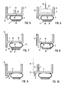
- Fig. 1 shows a connection profile strip 1 according to the invention with a profile body 2 comprising an outer leg 3 and a component mounting portion 4, wherein the outer leg 3 and the component mounting portion 4 via flexible connecting webs 5 vertically to each other and are movable transversely to each other, as shown by the crossed double arrows.
- two substantially vertically projecting Einputzstege 6, 7 are provided, wherein the outer Einsputzsteg 7 is formed extended into the region below the outer leg 3 and a Ver mannerssteg 8 forms, which extends as far to the side next to the outer connecting web 5 So this covers in the mounting position.
- an integrally formed sealing lip is shown at the lower edge of the trim strip 6, which consists of a softer plastic material than the hard profile body parts in the form of the outer leg 3 and the Einputzschenkel 6, 7 and the fairing web 8. While these example Hard PVC, the sealing lip 9, as provided, is formed of very soft, flexible soft PVC with low Shore hardness in a co-extrusion process.
- a cover strip 10 is projecting substantially at right angles thereto over a predetermined breaking point 11, here e.g. in the form of a material weakening, which carries an adhesive element 12, for example in the form of a double-sided adhesive tape (foam adhesive tape), which is glued to the top of Abdecklasche 10.
- the upper adhesive surface is covered with a protective strip, it can be exposed if necessary.
- a protective film can be glued, which serves to cover a subsequent window or the like.
- the cover flap 10 can be separated from the profile body 3 in the region of the predetermined breaking point 11.
- Fig. 1 an applied on the outside of the outer Einputzsteges 7 and the trim strip 8 pad 13, which serves to improve the adhesion of a applied plaster layer, with respect to what Fig. 2 will be discussed in more detail.
- This covering can be an applied fabric or a structured tape or applied fibers or chips etc. Any material which produces sufficient surface texturing or profiling to ensure that the applied plaster or the like adheres well is suitable. Instead of a covering, it would also be conceivable to provide the outside of the webs 7 and 8 themselves with a three-dimensional surface profiling, for. B. roughen or provided with notches or grooves.
- the outer leg 3 and the component mounting portion 4 are connected to each other via the flexible connecting webs 5.
- the connecting webs 5 themselves are part of a one-piece loop 14, which is fastened on the one hand to the outer leg 3 and forms a part of the component mounting section 4 with the lower loop section 15.
- the component mounting portion 4 is formed here from the loop portion 15, in the example shown, a double-sided adhesive foam adhesive tape 16 with a lower adhesive layer 17, which is covered with a protective tape to be deducted for adhering (silicone tape) is glued. About this adhesive layer 17, the attachment to the frame or rail component, which will be discussed below.
- the two connecting webs 5 in the areas 18 are firmly connected to the outer leg.
- the molding of the loop 14 on the outer leg 3 is advantageously also carried out in a co-extrusion process.
- the material of the loop 14 and thus that of the connecting webs 15 is very soft and flexible to choose, it may for example also be soft PVC, with a Shore hardness (eg Shore A ⁇ 30) as low as possible is select, so that the connecting webs 5 are highly flexible and allow a relative movement of the component mounting portion to the outer leg, even at very low acting transverse or longitudinal forces.
- Other soft plastics can be used, as well as a loop or the connecting webs may be made of rubber or a rubber-like material.
- the connecting webs are to be made as thin as possible, the wall thickness of the connecting webs 5 should be ⁇ 1 mm, it should preferably be in the range between 0.5 - 0.7 mm, but it is also not excluded, even thinner wall thicknesses, for example 0 , 3 or 0.4 mm, depending on the material used and the size of the strip as well as the intended use.
- the connecting webs 5 are evidently shaped curved outward. They are at a very shallow angle to the underside of the outer leg 3, so run from this as flat as possible and then go over into the bend. In a corresponding manner they run as flat as possible in the mounting portion 4, so that overall results in a relatively large bend or rounding.
- This geometry in combination with the high flexibility of the connecting webs, realized by the material used and the low web thickness, allows a highly flexible Relative movement of the component mounting portion 4 to the outer leg by the connecting webs 5 can be deformed or deformed in the manner of a rolling motion, which will be discussed below.
- Fig. 2 shows the profile strip 1 Fig. 1 in the assembly position. As can be seen, it is attached via the adhesive layer 17 to a component 19, for example to the window frame, which is connected via an adhesive or insulating layer 20 with a masonry 21.
- the profiled strip 1 is embedded in a plaster layer 22, which surrounds the Einputzstege 6, 7 as well as the U-shaped area between the Einsputzstegen 6, 7 and the outer leg 3 fills.
- the plaster layer 22 is also applied to the outside of the plasterboard 7 and the local coating 13, so that the profiled strip 1 is almost completely hidden.
- the profile body 2 is therefore not visible. It remains only a very narrow shadow gap 23 between the lower edge of the panel web 8 and the component 19.
- This shadow gap is for example 1 - 2 mm, that is, the joint allows a vertical movement of the mounting portion 4 relative to the outer leg in a building movement.
- the size of the shadow gap ultimately depends on the size of the profile strip. Basically, the shadow gap should be in the range of one or less millimeters.
- the outer side of the profiled strip 1 can be placed completely under plaster over the formation of the covering web 8 in conjunction with the applied adhesive coating 13, so that the profile strip is not visible and forms a clean, visually appealing shadow gap 23, which kept so narrow can be that the area behind it is not visible.
- FIGS. 3 and 4 show two views in which the component mounting portion 4 is displaced relative to the outer leg 3.
- Fig. 3 is the component mounting portion 4, as shown by the arrow, moved far to the right.
- the connecting webs 5 are so flexible and can be deformed so easily in the form of their bent geometry that a rolling movement takes place at a force in the horizontal direction.
- the overlapping connecting web sections shift of the two connecting webs 5 in this case, they slide away one above the other, so that there is a total of a rolling or rolling-like movement, as is known per se in such a loop geometry.
- the curved configuration allows a considerable movement or displacement path to the side, be it to the right or (see Fig. 4 ) left to.
- the maximum movement length ultimately depends on the free length of the connecting webs 5, which in turn depends on the distance of the component mounting portion 4 to the outer leg and the bending radius. Movement distances of 2 - 4 mm in each direction are conceivable and feasible, with larger profile strips certainly more. Also, a vertical movement in the range of several millimeters, depending on the distance from the component mounting portion to the outer leg 3, given, wherein the component mounting portion 4 is also moved slightly vertically to the outer leg 3 in a horizontal movement.
- FIGS. 5 to 10 show various embodiments of the invention connecting profiled strips. As far as possible, the same reference numerals are used to designate the same elements. Basically, the structure of each profile strip is essentially the same. In each case, an outer leg 3 made of hard plastic material is provided, with which a fastening section 4 is coupled in a highly flexible manner via the connecting webs 5. In Fig. 5 the connecting webs 5 are connected in the region of attachment to the outer leg 3 via a connecting portion 24, that is, it forms here a total of a tubular loop 14, which is thus completely closed. This results in a very large-scale connection to the outer leg 3 in a single, very wide connection area 18, unlike the embodiment according to Fig. 1 where two separate connection areas 18 are provided.
- a further central anchoring web 25 is here in addition to the two edge Einputzstegen 6, 7 is provided, which is optional.
- the cover tabs 10 are not shown in this and the following embodiments. These can be provided, but not necessarily.
- the adhesive layer 17 is applied here by way of example directly to the loop 14 or the loop section 15, and no foam tape is arranged therebetween.
- the component mounting portion 4 is not formed by a foam adhesive tape 16 with adhesive layer 17 underneath, but rather a relatively stiff, preferably also made of harder material (corresponding to the material of the outer leg 3, eg hard PVC) on the loop portion 15 Stiffening strip 26 arranged, which can also be formed in a co-extrusion process.
- a stiffer attachment portion 4 as compared to the more elastic attachment portion 4 comprising the soft foam adhesive tape 16.
- an adhesive layer 17 is also applied to the stiffening strip 26, in this case directly.
- a plaster fabric 28 added, which is integrated into the plaster layer for even better anchoring.
- the soft plastic loop 14 is again arranged in two separate attachment areas 18 on the outer leg 3. Again, a stiffening strip 26 is placed on the loop portion 15, but here on a foam adhesive tape 16, which carries the adhesive layer 17, is applied.
- the fairing leg 8 is pulled down a little further because of entire structure below the outer leg 3 is slightly stronger to cover this largely to form the shadow gap.
- a further embodiment of a profiled strip 1 according to the invention Fig. 8 also there, the material loop 14 is arranged from highly flexible soft plastic material in a single, large-scale attachment portion on the outer leg 3.
- the ends of the connecting webs 5 are arranged here in separate attachment regions 29 on a stiffening strip 26, so that no central loop section 15 is formed here as in the previously described embodiments.
- the high relative mobility can also be realized in such an embodiment, since here too, the connecting webs 5 can perform the unrolling or rolling movement according to the invention when a transverse force is introduced due to their geometry and highly flexible design. It would also be conceivable to arrange the two connecting webs 5 in this embodiment also on the outer leg 3 in two separate attachment areas 18.
- Fig. 9 shows a further profile strip, the structure of the profile strip 1 Fig. 1 equivalent.
- a separate sealing lip 9 is provided, which is integrally formed on the underside of the outer leg 3 and ends in the mounting position in the shadow gap 23. As described, such a sealing lip is optional.
- Fig. 10 shows a profiled strip according to the invention, the forth from the basic structure, as far as the design of the movement coupling, etc., in the example shown, the bar off Fig. 1 equivalent.
- the outer Einputzsteg 7 is not disposed on the edge of the outer leg 3, but slightly offset inwards, so that there is a quasi-step shape.
- the fairing web 8 in turn is integrally formed on the outer side edge 3. Both are each provided here with an adhesion-improving coating 13 and can, as shown by way of example, be covered with a plaster layer 22.
- FIGS. 11-13 show three further embodiments that show various adhesion-improving coverings.
- Fig. 11 shows a profile strip 1, in which it is can be any profile strip of the type described above.
- the adhesion-improving coating 13 here consists of a structured fabric 30, as indicated by the intersecting fabric threads.
- the fabric 30 is made of plastic, but may also be formed from textile fibers. The use of a glass fiber fabric is conceivable.
- the fabric itself has an adhesive surface on which it is glued to the outside of the Einputzsteges 7. It is also conceivable, however, first to apply an adhesive layer to the outside of the outer web 7, to which the fabric is then glued.
- the fabric which may be woven relatively coarse mesh, for example, so that they open structure as possible, in which the plaster layer can dig, also extends over the panel web 8 so that it can be completely plastered.
- the material used to form the fabric 30 may be any, but care must be taken that the material is chemically resistant in that it can not be attacked by any ingredients contained in the plaster layer.
- Fig. 12 shows a profiled strip 1 with an adhesion-improving coating 13 in the form of a glued, structured band 31.
- This band is for example made of plastic and embossed over the surface to form knob-like elevations 32 in the example shown.
- the tape 31 may be self-adhesive, thus having its own adhesive surface, via which it is glued to the outside of the Einputzsteges 7 and the fairing web 8.
- the respective outer side can be provided with an adhesive layer, on which the tape 31 is then glued.
- the knob-like elevations 32 it would of course also be conceivable to form recesses, that is to say to perforate the band 31 so as to structure the surface.
- longitudinal elevations or obliquely running elevations or grooves can be pronounced etc.
- the type of three-dimensional structuring is arbitrary.
- this plastic band for example, a band of PVC, offers the possibility that the plaster layer firmly anchored. It is also conceivable, however, the use of a textile felt or a flocked, so very thin, dense protruding fibers having tape.
- Fig. 13 shows a connection profile strip 1, in which on the outside of the Einputzsteges 7 and the fairing web 8 particles 33 produce the surface structuring.
- the particles 33 are embedded in a carrier medium 34, for example a cured adhesive or a resin layer. This also results in a rough, textured surface to which the plaster adheres over a large area and safely.
- the carrier medium can first be brought to the outside, for example brushed or sprayed on, after which the particles 33, which are, for example, sand or quartz powder, are sprinkled. It is also conceivable, however, to mix these particles into the still viscous carrier medium and then apply the mixture and cure the carrier medium.
- the sand or quartz flour particles it would also be conceivable to apply glass or plastic or wood or metal particles for structuring.
- Fig. 14 finally also shows a profiled strip 1, in which the coating 13 is formed by fibers 36 fixed in a carrier medium 35.
- the fibers 36 may be, for example, plastic or textile fibers.
- the fibers 36 are drawn relatively coarse, so they can also be very fine, so thin and short, so that a total of flocking forms, as in Fig. 14 is additionally shown by the very short fibers 36 '.
- Fig. 15 shows a further embodiment of a bar according to the invention, in which on the outer leg 3 compared to the connecting webs 5 much firmer, more stable connecting webs 37, a component mounting portion 4 forming stiffening strip 26 is provided with the adhered thereto foam adhesive tape 16 with the adhesive layer 17.
- an adhesion-improving coating 13 of any kind is provided on the outer plaster web 7.
- a holding or clamping section 27 piping inserted between the two webs 6, 7, with a plaster fabric 28.
- the various profile bodies 2 shown or configurations of the structure on the outer leg, etc. can be combined with any desired configurations of the fastening section 4 as well as arbitrary configurations of the connecting webs 5 or their connection to the outer leg 3 or to the fastening section 4.
- the various strips can be provided with a lateral Abdecklasche.
- a three-dimensional surface structure can also be formed on the outer web sides themselves.
- the adhesive layer can be applied directly to the loop portion or the fastening portion.
Abstract
Description
Die Erfindung betrifft eine Anschlussprofilleiste, insbesondere Laibungsanschlussprofilleiste, mit einem Profilkörper mit einem Außenschenkel und einem mit diesem über Verbindungsstege beweglich verbundenen Rahmenbefestigungsabschnitt zum Befestigen der Leiste an einem Rahmen- oder Schienenbauteil, insbesondere einem Tür- oder Fensterrahmen oder einer Rolloschiene, über eine Klebefläche, wobei am Profilkörper ein den in der Montagestellung äußeren Verbindungssteg zumindest teilweise, vorzugsweise vollständig verdeckender Verkleidungssteg vorgesehen ist.The invention relates to a connection profile strip, in particular soffit connection profile strip, with a profile body with an outer leg and with this via connecting webs movably connected frame mounting portion for attaching the bar to a frame or rail component, in particular a door or window frame or a roller blind rail, via an adhesive surface, said the profiled body is provided at least partially, preferably completely concealing, facing web in the assembly position outer connecting web.
Derartige Profilleisten dienen zumeist der Herstellung eines Übergangs zwischen einem Fenster- oder Türrahmen oder einer Rolloschiene und einer daran anschließenden Wand, wobei bekannte Anschlussprofile entweder an eine Putzschicht anschließen, oder aber der Aufnahme von Verkleidungsplatten oder dergleichen dienen. Bei bekannten Leisten ist mitunter eine relative Beweglichkeit des Bauteilbefestigungsabschnitts, also des Profilkörperteils, der über die Klebefläche am Rahmen oder der Schiene befestigt ist, zum Außenschenkel, an dem beispielsweise vorspringende Stege oder dergleichen vorgesehen sind, über Verbindungsstege realisiert, die den Außenschenkel und den Bauteilbefestigungsabschnitt verbinden, und die aus einem weicheren Material als der Außenschenkel und der Bauteilbefestigungsabschnitt bestehen, beispielsweise Weich-PVC, während die anderen Profilkörperteile aus Hart-PVC bestehen. Diese relative Beweglichkeit ermöglicht es zu einem gewissen Grad, etwaige sich im Laufe der Zeit einstellende Bewegungen zwischen dem Rahmen- oder Schienenbauteil und der Putzfläche, in der der Außenschenkel verankert ist, kompensieren zu können und gleichzeitig die über die Leiste realisierte Anbindung und Abdichtung aufrecht zu halten. Häufig ist am Außenschenkel ein von diesem im wesentlichen vertikal abstehender seitlicher Steg vorgesehen, an den sich nach dem Aufbringen der Putzschicht auf das benachbarte Mauerwerk o.dgl. die Putzschicht anschließt. Der Steg ist also in der Montagestellung sichtbar, er bildet einen sauberen Anschluss an die Putzschicht. Optisch sichtbar bleibt weiterhin aber auch der Bereich unterhalb des Außenschenkels mit den Verbindungsstegen und dem Bauteilbefestigungsabschnitt umfassend z.B. das relativ dicke Schaumstoffklebeband. Mitunter ist am Befestigungsabschnitt eine zur Seite vorspringende Dichtlippe angeformt, die das Schaumstoffklebeband überdeckt, so dass in diesem Fall diese Dichtlippe sichtbar wäre. Die Sichtbarkeit dieses Bereichs ist somit mitunter aus optischen Gründen nicht ansprechend.Such moldings are usually used to produce a transition between a window or door frame or a roller blind rail and an adjoining wall, with known connection profiles either connect to a plaster layer, or serve the inclusion of cladding panels or the like. In known strips is sometimes a relative mobility of the component mounting portion, so the profile body part, which is attached via the adhesive surface on the frame or the rail to the outer leg, are provided on the example projecting webs or the like, realized via connecting webs, the outer leg and the component mounting portion connect, and which consist of a softer material than the outer leg and the component mounting portion, such as soft PVC, while the other profile body parts made of rigid PVC. This relative mobility makes it possible, to a certain extent, to be able to compensate for any movements that occur over time between the frame or rail component and the plaster surface in which the outer leg is anchored and at the same time maintain the connection and sealing realized via the strip hold. Frequently, a substantially vertically projecting from this side web is provided on the outer leg, to which after the application of the plaster layer on the adjacent masonry or the like. the plaster layer connects. The bridge is thus visible in the mounting position, it forms a clean connection to the plaster layer. However, the region below the outer leg with the connecting webs and the component fastening section remains optically visible as well comprising, for example, the relatively thick foam adhesive tape. Occasionally, a side-projecting sealing lip is formed on the attachment portion, which covers the foam adhesive tape, so that in this case this sealing lip would be visible. The visibility of this area is therefore sometimes not appealing for visual reasons.
Der Erfindung liegt damit das Problem zugrunde, eine Anschlussprofilleiste anzugeben, die optisch ansprechender verarbeitet werden kann.The invention is thus based on the problem of specifying a connection profile strip, which can be processed visually appealing.
Zur Lösung dieses Problems ist bei einer Anschlussprofilleite der eingangs genannten Art erfindungsgemäß vorgesehen, dass am Profilkörper ein in der Montagestellung äußerer Einputzsteg, der vorzugsweise vertikal vom Außenschenkel absteht, vorgesehen ist, der zur Bildung des Verkleidungsstegs verlängert ausgebildet ist, wobei die Außenseite des Einputzstegs und des Verkleidungsstegs mit einem die Haftung einer aufzubringenden Putz- oder Farbschicht verbessernden Belag oder einer haftungsverbessernden dreidimensionalen Oberflächenstruktur versehen ist.To solve this problem is provided according to the invention in a connection profile of the aforementioned type that on the profile body in the mounting position outer Einputzsteg, which preferably protrudes vertically from the outer leg, is provided, which is formed extended to form the fairing web, the outside of the Einputzstegs and the cladding web is provided with a covering which improves the adhesion of a plaster or paint layer to be applied or with an adhesion-improving three-dimensional surface structure.
Dieser Verkleidungssteg, der bevorzugt nahe der oder an der Kante des Außenschenkels angeordnet ist, erstreckt sich also um ein gewisses Stück seitlich der vorgesehenen Verbindungsstege und gegebenenfalls des Schaumstoffklebebands, deckt also den unterhalb des Außenstegs befindlichen Bereich zumindest teilweise ab. Es verbleibt in der Montagestellung damit eine Schattenfuge zum Rahmenbauteil, die je nachdem, wie weit der Verkleidungssteg gezogen ist, mehr oder weniger breit ist. Die endgültige Fugenbreite ist letztlich von der konkreten Ausgestaltung der Profilleiste, insbesondere der eigentlichen Größe bzw. dem Profilkörperaufbau abhängig. Sie liegt z.B. im Bereich zwischen ca. 1 - 10 mm, vorzugsweise zwischen 1 - 5 mm, insbesondere zwischen 1 - 3 mm, wobei bei kleineren Leisten eine Fugenbreite von beispielsweise 1 - 3 mm realisierbar ist, da die von diesen Leisten aufzunehmenden Bauteilverschiebungen anzunehmenderweise nicht allzu groß sind, während bei großen Profilleisten auch Fugen von beispielsweise 5 mm und mehr verbleiben können. Diese verbleibende Schattenfuge, die jedoch in der Montagestellung grundsätzlich möglichst klein gehalten werden sollte, ist optisch ansprechend, sichtseitig ist also letztlich lediglich der Verkleidungssteg als geradliniges Sichtelement zu sehen, was optisch ansprechend ist.This fairing web, which is preferably arranged close to or at the edge of the outer leg, thus extends to some extent laterally of the intended connecting webs and optionally of the foam adhesive tape, so at least partially covers the area located below the outer web. It remains in the mounting position thus a shadow gap to the frame member, which is more or less wide, depending on how far the fairlead is pulled. The final joint width is ultimately dependent on the specific design of the profile strip, in particular the actual size or the profile body structure. It is for example in the range between about 1 - 10 mm, preferably between 1 - 5 mm, in particular between 1 - 3 mm, with smaller strips a joint width of, for example, 1 - 3 mm can be realized, as assumed by these strips component displacements not too large, while with large moldings and joints, for example, 5 mm and more may remain. This remaining shadow gap, which are, however, kept as small as possible in the mounting position should, is visually appealing, so in the end, therefore, only the fairing web is to be seen as a straight-line visual element, which is visually appealing.
Dabei ist ein äußerer Einputzsteg, der vorzugsweise vertikal vom Außensteg absteht, zur Bildung des Verkleidungsstegs verlängert ausgebildet. Dieser Steg, der an der Putzschicht wie beschrieben in der Montagestellung anschließt, wird nun erfindungsgemäß nach unten verlängert, so dass der Verkleidungssteg in unmittelbarer Verlängerung ausgebildet wird. In der Montagestellung ist damit eine einheitliche Fläche gegeben, es bleibt lediglich die möglichst schmale Schattenfuge, vom unterhalb des Außenschenkels liegenden Bereich ist nichts mehr sichtbar. Hieraus ergibt sich ein sehr ansprechendes, homogenes Erscheinungsbild.In this case, an outer Einputzsteg, which preferably protrudes vertically from the outer web, formed extended to form the fairing web. This web, which connects to the plaster layer as described in the assembly position, is now according to the invention extended downwards, so that the cladding web is formed in the immediate extension. In the assembly position so that a uniform surface is given, it remains only the narrowest possible shadow gap, from the lying below the outer leg area is no longer visible. This results in a very attractive, homogeneous appearance.
Ferner ist vorgesehen sein, dass der in der Montagestellung äußere Einputzsteg an seiner Außenseite mit einem die Haftung einer aufzubringenden Putz- oder Farbschicht verbessernden Belag oder eine hierfür dienende Oberflächenstruktur, z. B. einer Aufrauung versehen ist. Es ist ein Einputzsteg vorgesehen, der also selbst eingeputzt wird, in der Montagestellung also unter Putz liegt. Er dient also als Putz- oder Farbträger, das heißt, er wird außenseitig vollständig eingeputzt oder gestrichen, so dass er in der Montagestellung nicht sichtbar ist. Um eine optimale Haftung des Putzes oder einer Farbschicht zu er-möglichen, ist die Außenseite des Einputzsteges mit einem entsprechenden haftungsverbessernden Belag versehen oder dreidimensionale strukturiert. Über diesen Belag oder die Oberflächenstruktur wird eine sichere Verankerung der aufgebrachten Putz- oder Farbschicht auf der Einputzstegaußenfläche gewährleistet, so dass vermieden wird, dass es im Laufe der Zeit zu einem Ablösen der Putz- oder Farbschicht kommt. In der Montagestellung ist damit von der Profilleiste wenn überhaupt nur noch der unterhalb des Außenstegs anschließende Leistenteil sichtbar.Furthermore, it can be provided that the exterior in the mounting position Einputzsteg on its outside with a the adhesion of a applied plaster or paint layer improving coating or serving for this surface structure, eg. B. is provided a roughening. It is a Einputzsteg provided, which is so even plastered, so in the mounting position is under plaster. It therefore serves as a plaster or color carrier, that is, it is completely plastered or painted on the outside, so that it is not visible in the mounting position. In order to ensure optimum adhesion of the plaster or a layer of paint, the outside of the plasterboard is provided with a corresponding adhesion-improving coating or structured three-dimensional. Over this covering or the surface structure a secure anchoring of the applied plaster or paint layer is ensured on the Einputzstegaußenfläche, so that it is avoided that in the course of time to a detachment of the plaster or paint layer. In the assembly position is thus visible from the profile strip if at all only the subsequent below the outer web strip part.
Auch der erfindungsgemäß vorgesehene Verkleidungssteg kann optisch ansprechend versteckt werden, wenn, wie erfindungsgemäß ferner vorgesehen ist, auch der Verkleidungssteg mit einem solchen die Haftung der aufzubringenden Putz- oder Farbschicht verbessernden Belag oder einer solchen Haftstruktur versehen ist. Insbesondere wenn der Einputzsteg verlängert ist und unmittelbar in den Verkleidungssteg übergeht, ist es ohne weiteres möglich, den haftungsverbessernden Belag auf der gesamten Profilkörperaußenseite, gebildet durch die Außenseite des Einputzsteges und des Verkleidungssteges, aufzubringen oder die genannte Seite mit der Strukturierung zu versehen. Die Profilleiste ist dann vollständig unter Putz oder Farbe verschwunden, es ist lediglich noch die Schattenfuge zu sehen. Gleichzeitig aber bleiben die hervorragenden Eigenschaften der erfindungsgemäßen Leiste hinsichtlich der Aufnahme von Längs- und Querkräften aufgrund des arbeitenden Bauwerks erhalten.The cover web provided according to the invention can also be concealed in an optically appealing manner if, as is furthermore provided according to the invention, the cover web also bears the adhesion of the plaster surface to be applied. or color layer improving coating or such an adhesive structure is provided. In particular, if the Einputzsteg is extended and merges directly into the panel web, it is easily possible to apply the adhesion-improving coating on the entire profile body outside, formed by the outside of the Einputzsteges and the fairing web, or to provide said side with the structuring. The profile strip is then completely gone under plaster or paint, it is only the shadow gap to see. At the same time, however, the excellent properties of the strip according to the invention with regard to the absorption of longitudinal and transverse forces due to the working structure are retained.
Hinsichtlich des verwendbaren Belags sind unterschiedliche Möglichkeiten gegeben. Nach einer ersten Erfindungsalternative kann der Belag ein vorzugsweise aufgeklebtes strukturiertes Band, z. B. ein Kunststoff- oder Textilband, oder ein aufgeklebtes Gewebe (z. B. ein Glasfasergewebe) oder nach Art einer Beflockung aufgebrachte Fasern, jeweils insbesondere aus Kunststoff oder Textil, sein. Über das Band oder Gewebe oder die Fasern wird eine Oberflächenstrukturierung erreicht, die es ermöglicht, dass sich insbesondere die Putzschicht fest in die Oberflächenstruktur verkrallen kann. Das Band oder das Gewebe bzw. die Flocken können aus Kunststoff sein. Beispielsweise kann ein perforiertes oder anderweitig dreidimensional verformtes Kunststoffband, gegebenenfalls rückseitig mit einer selbstklebenden Schicht versehen, aufgeklebt werden. Das Gewebe kann beispielsweise ein aus Kunstfasern hergestelltes Textilgewebe sein, das beispielsweise sehr grob gewebt ist bzw. aus dicken Fasern besteht, so dass sich eine entsprechende "offenporige" Webstruktur ergibt. Zur "Beflockung" können bevorzugt Kunststofffasern von einem oder mehreren Millimetern Länge verwendet werden, die beispielsweise auf eine zuvor aufgebrachte Klebeschicht aufgebracht werden, oder die gegebenenfalls in einer aushärtenden oder selbstklebenden Trägermasse enthalten sind, die auf die Außenseite des Einputzsteges und gegebenenfalls des Verkleidungsstegs aufgetragen wird. Die in die Trägermasse eingebetteten Fasern stehen aus dieser vor, bilden also eine dreidimensional strukturierte Oberfläche, wenn das Trägermaterial, beispielsweise ein aushärtender Klebstoff oder Kunstharz, ausgehärtet ist. Hinsichtlich des verwendeten Bandes bzw. Gewebes bzw. der Fasern sind keine Beschränkungen gegeben, so lange sich die haftungsverbessernde Strukturierung der Stegoberfläche erzielen lässt.With regard to the usable surface different possibilities are given. According to a first alternative of the invention, the pad may be a preferably glued structured band, z. Example, a plastic or textile tape, or a glued fabric (eg., A glass fiber fabric) or on the type of flocking applied fibers, each in particular of plastic or textile, be. Over the tape or fabric or fibers, a surface structuring is achieved, which makes it possible that in particular the plaster layer can dig into the surface structure. The tape or fabric or flakes may be plastic. For example, a perforated or otherwise three-dimensionally deformed plastic tape, optionally provided on the back with a self-adhesive layer, are glued. The fabric can be, for example, a textile fabric made of synthetic fibers which, for example, is woven very coarsely or consists of thick fibers, so that a corresponding "open-pored" weave structure results. For "flocking" preferably plastic fibers of one or more millimeters in length can be used, which are applied for example to a previously applied adhesive layer, or which are optionally contained in a curing or self-adhesive support material, which is applied to the outside of the Einputzsteges and optionally the panel web , The fibers embedded in the carrier mass protrude from this, thus forming a three-dimensionally structured surface when the carrier material, for example a curing adhesive or synthetic resin, has hardened. With regard to the used band or tissue or There are no restrictions on the fibers as long as the adhesion-enhancing structuring of the web surface can be achieved.
Alternativ zu den beschriebenen Belägen kann der Belag auch ein klebendes oder ausgehärtetes Trägermedium mit darauf aufgebrachten oder darin eingebrachten Partikeln, insbesondere Quarzmehl oder Sand, sein. Die Strukturierung erfolgt hier über auf- oder eingebrachte Partikel, wobei vornehmlich Quarzmehl oder Sand verwendet wird, zumal Quarzmehl oder Sand alkalisch beständig sind, was im Hinblick auf aufzubringende Putzschichten von Vorteil ist. Die Partikel, unabhängig davon, welche Partikel eingebracht oder aufgebracht werden, sollten eine Größe von wenigstens 0,5 mm, vorzugsweise 1 mm oder mehr, haben, um eine hinreichende Oberflächenrauigkeit zu verleihen. Dabei kann das Aufbringen der Partikel derart erfolgen, dass zunächst auf die Stegaußenseite eine Klebeschicht oder ein Trägermedium aufgebracht wird, auf das dann die Partikel gestreut werden. Denkbar ist aber auch die Verwendung einer entsprechend applizierbaren viskosen Masse, bestehend aus dem Trägermedium und darin eingemischten Partikeln, vorzugsweise Sand, welche Masse auf die Stegaußenseite aufgebracht wird und anschließend aushärtet.As an alternative to the coatings described, the coating may also be an adhesive or cured carrier medium with particles applied thereto or incorporated therein, in particular quartz powder or sand. The structuring is carried out here by on or introduced particles, primarily quartz powder or sand is used, especially quartz powder or sand are alkaline resistant, which is advantageous in terms of applied plaster layers. The particles, regardless of which particles are introduced or applied, should have a size of at least 0.5 mm, preferably 1 mm or more, to impart sufficient surface roughness. In this case, the application of the particles can take place in such a way that first an adhesive layer or a carrier medium is applied to the web outside, onto which the particles are then scattered. However, it is also conceivable to use a correspondingly applicable viscous mass, consisting of the carrier medium and particles mixed therein, preferably sand, which mass is applied to the web outside and then cured.
Schließlich kann der Belag auch eine Haftbrücke sein, also eine Beschichtung, die per se keine dreidimensionale Strukturierung aufweist, sondern aufgrund ihrer chemischen oder physikalischen Eigenschaften einen besonders haftfähigen Untergrund für die darauf aufzubringende Putz- oder Farbschicht bietet. Diese Haftbrückenbeschichtung wird im flüssigen Zustand auf die Außenseite aufgetragen und härtet anschließend aus.Finally, the coating may also be a bonding agent, ie a coating which per se does not have a three-dimensional structure, but on account of its chemical or physical properties offers a particularly adhesive substrate for the plaster or color coat to be applied thereto. This adhesive layer coating is applied to the outside in the liquid state and then cured.
Gemäß einer zweckmäßigen Weiterbildung zeichnet sich die erfindungsgemäße Anschlussprofilleiste ferner dadurch aus, dass die aus einem verformbaren Material bestehenden Verbindungsstege derart flexibel und gebogen ausgebildet sind, dass sie bei einer horizontalen Verschiebung des Befestigungsabschnitts relativ zum Außenschenkel in einer abrollartigen Bewegung verformbar sind. Sie zeichnet sich also durch hochflexible Verbindungsstege aus, die also aus einem sehr weichen, elastisch sehr leicht verformbarem Material bestehen, so dass mithin die Verbindungsstege einer einwirkenden Bewegungs- oder Verschiebekraft einen kaum merklichen Widerstand entgegensetzen. Das verwendete Kunststoff- oder Gummimaterial sollte also eine möglichst niedrige Shore-Härte aufweisen, beispielsweise eine Härte Shore ≤ A50, vorzugsweise ≤ A30. Diese hohe Flexibilität ermöglicht es, dass sich die Profilleiste sehr einfach und vollständig einer etwaigen Bauwerksbewegung anpassen kann und insbesondere auf den Verbindungsbereich des Bauteilbefestigungsabschnitts zum Rahmen- oder Schienenbauteil bei einer Verschiebung wenn überhaupt nur minimale Kräfte einwirken, da die Verbindungsstege aufgrund ihrer sehr leichten Verformbarkeit keine Spannungen oder Kräfte auf den Rahmenbefestigungsabschnitt und über diesen die Klebeverbindung zum Rahmen- oder Schienenbauteil ausüben.According to an expedient development, the connection profile strip according to the invention is further distinguished by the fact that the connecting webs consisting of a deformable material are designed to be flexible and curved in such a way that they can be deformed in a rolling movement with a horizontal displacement of the fastening section relative to the outer leg. So it is characterized by highly flexible connecting webs, which thus consist of a very soft, elastic very easily deformable material, so that therefore the Connecting webs an acting movement or displacement force oppose a barely noticeable resistance. The plastic or rubber material used should therefore have the lowest possible Shore hardness, for example, a hardness Shore ≤ A50, preferably ≤ A30. This high flexibility allows the profile strip can very easily and completely adapt to any building movement and in particular the connection region of the component mounting portion to the frame or rail component in a shift if at all minimal forces act, since the connecting webs due to their very easy deformability no Apply stresses or forces on the frame attachment portion and over this the adhesive bond to the frame or rail component.
Weiterhin zeichnet sich die Anschlussprofilleiste dadurch aus, dass die hochflexiblen Verbindungsstege gebogen ausgebildet sind, so dass sie eine einfache Horizontalverschiebung ermöglichen und bei dieser eine abroll- oder abwälzartige Bewegung durchführen. Das heißt, die Verbindungsstege sind von Haus aus gebogen ausgeführt, bevorzugt nach außen gebogen. Wirkt nun eine Kraft auf die Verbindungsstege in Horizontal- oder Querrichtung ein, so reagieren diese aufgrund ihrer hohen Flexibilität sofort und rollen oder wälzen sich, der Kraft folgend, zur Seite hin ab. Über diese Abroll- oder Abwälzeigenschaft kann eine beachtliche Bewegungsstrecke, längs welcher also die Relativverschiebung des Rahmenbefestigungsabschnitts zum Außenschenkel möglich ist, realisiert werden. Bewegungsstrecken von 3 - 4 mm nach jeder Seite, ausgehend von der Mittenstellung, sind ohne weiteres realisierbar. Die erfindungsgemäße Anschlussprofilleiste lässt also eine Bewegungskompensation der verbundenen Bauwerksteile zu, wobei sie bereits bei minimalen Bewegungen bzw. einwirkenden Kräften im Verbindungsstegbereich reagiert und imstande ist, auch große bauwerksseitige Bewegungsstrecken vollständig aufnehmen zu können, ohne dass die Gefahr besteht, dass der Anschluss beispielsweise im Bereich der Verklebung des Bauteilbefestigungsabschnitts aufreißt.Furthermore, the connection profile strip is characterized in that the highly flexible connecting webs are formed bent, so that they allow a simple horizontal displacement and carry out a rolling or rolling-like movement in this. That is, the connecting webs are designed bent home, preferably bent outwards. Now acts a force on the connecting webs in a horizontal or transverse direction, they respond immediately because of their high flexibility and roll or roll, following the force, to the side from. About this rolling or Abwälzeigenschaft a considerable movement distance, along which therefore the relative displacement of the frame mounting portion to the outer leg is possible, can be realized. Movements of 3 - 4 mm to each side, starting from the center position, are readily feasible. The connection profile strip according to the invention thus allows for motion compensation of the connected structural parts, wherein it reacts even with minimal movements or acting forces in the connecting bridge area and is able to completely accommodate even large construction-side movement distances, without the risk that the connection, for example in the area the bonding of the component mounting portion ruptures.
Um eine möglichst große Abroll- oder Abwälzstrecke zu realisieren, münden die Verbindungsstege unter einem möglichst kleinen, spitzen Winkel am Außenschenkel bzw. dem Befestigungsabschnitt, bevorzugt stehen sie zum Außenschenkel und zum Befestigungsabschnitt unter einem Winkel ≤ 45°, insbesondere ≤ 30°. Die gebogenen Stege münden also möglichst flach, woraus sich eine relativ große, freie gebogene Steglänge ergibt, und daraus resultierend eine große Verschiebe- oder Abrolllänge. Der Abstand des Außenschenkels zum Befestigungsabschnitt, bezogen auf die Innenseiten, beträgt wenigstens 2 mm. In Verbindung mit dem sehr flachen Winkel der Stege relativ zu dem Außenschenkel und dem Befestigungsabschnitt ergeben sich hieraus zwangsläufig große freie Schenkellängen. Die Dicke der Verbindungsstege sollte ≤ 2 mm, insbesondere ≤ 1 mm, und vorzugsweise im Bereich zwischen 0,5 - 0,7 mm liegen. Je dünner die Verbindungsstege sind, um so größer ist die Flexibilität dieses Verformungsabschnitts, wobei die Dicke der Verbindungsstege natürlich auch unter Berücksichtigung des Abstands des Außenschenkels vom Befestigungsabschnitt wie auch des Abstands der Verbindungsstege voneinander selbst, mithin also letztlich der Größe des Profilkörpers gewählt werden kann. Jedoch hat sich eine Stegbreite ≤ 1 mm, insbesondere im angegebenen Bereich zwischen 0,5 - 0,7 mm bei den üblichen Anschlussprofilleistengrößen als besonders zweckmäßig erachtet. Dabei ist hier darauf hinzuweisen, dass selbstverständlich auch alle anderen Werte oberhalb von 0,7 mm und unterhalb von 0,5 mm als erfindungswesentlich offenbart gelten.In order to realize the largest possible rolling or rolling distance, the connecting webs open at a small, acute angle on the outer leg or the attachment portion, they are preferably to the outer leg and the attachment portion at an angle ≤ 45 °, in particular ≤ 30 °. The curved webs thus open as flat as possible, resulting in a relatively large, free curved web length, resulting in a large displacement or Abrolllänge. The distance of the outer leg to the attachment portion, based on the inner sides, is at least 2 mm. In conjunction with the very shallow angle of the webs relative to the outer leg and the attachment portion resulting from this necessarily large free leg lengths. The thickness of the connecting webs should be ≦ 2 mm, in particular ≦ 1 mm, and preferably in the range between 0.5 to 0.7 mm. The thinner the connecting webs, the greater the flexibility of this deformation section, wherein the thickness of the connecting webs of course, taking into account the distance of the outer leg of the mounting portion as well as the distance of the connecting webs from each other, therefore ultimately the size of the profile body can be selected. However, a web width ≤ 1 mm, especially in the specified range between 0.5 - 0.7 mm in the usual connection profile list sizes has been found to be particularly useful. It should be noted here that, of course, all other values above 0.7 mm and below 0.5 mm apply as essential to the invention.
Die Verbindungsstege, die aus einem möglichst weichen, elastischen Kunststoff- oder Gummimaterial bestehen, werden zweckmäßigerweise mit den sonstigen Bauteilen des Profilkörpers, soweit diese aus Kunststoff extrudiert werden, gemeinsam in einem Coextrusionsverfahren hergestellt, mithin also angeformt. Dies gilt bezüglich jeder erfindungsgemäßen Ausgestaltung der Anschlussprofilleite. Dabei kann nach einer ersten Erfindungsalternative vorgesehen sein, dass die Verbindungsstege Teil einer einstückigen, am Außensteg angeordneten Schlaufe sind, die den oder zumindest einen Teil des Befestigungsabschnitts bildet. Bei dieser Ausgestaltung der Leiste ist am beispielsweise aus Hart-PVC bestehenden Außensteg eine beispielsweise aus sehr weichem Weich-PVC einstückig ausgebildete Schlaufe angeformt, die quasi eine Hohlkammer darstellt und die beiden Verbindungsstege bildet. Ferner bildet sie auch entweder den Befestigungsabschnitt selbst, auf den dann unmittelbar die Klebeschicht aufgebracht ist oder beispielsweise ein Schaumstoffband mit der unterseitigen Klebeschicht, oder sie bildet einen Teil des Befestigungsabschnitts, an welchem Teil dann eine weitere Leiste oder dergleichen aus härterem Material angeformt ist, die dann die Klebeschicht oder das Schaumstoffband etc. trägt. Hierauf wird nachfolgend noch eingegangen. Bei dieser Erfindungsausgestaltung wird also am Außensteg eine komplette Schlaufe angeformt, die multifunktional ist und eben die Verbindungsstege wie auch den Befestigungsabschnitt selbst bzw. zumindest eines Teils davon bildet. Dabei kann die Dicke des Schlaufenabschnitts, der den oder einen Teil des Befestigungsabschnitts bildet, gleicher oder größer als die Dicke des Verbindungssteges sein. Aus Stabilitäts- oder Festigkeitsgründen ist es ausreichend, wenn die Schlaufe überall eine einheitliche Dicke aufweist. Mitunter kann es aber, beispielsweise wenn auf dem den Befestigungsabschnitt bildenden Teil des Schlaufenabschnitts unmittelbar eine Klebeschicht oder ein diese tragendes Schaumstoffklebeband aufgeklebt wird, zweckmäßig sein, diesen Schlaufenabschnitt etwas stärker, also stabiler auszuführen.The connecting webs, which consist of the softest possible, elastic plastic or rubber material, are expediently produced together with the other components of the profile body, insofar as they are extruded from plastic, in a coextrusion process, thus also formed. This applies with respect to each embodiment of the invention the Anschlussprofilleite. It can be provided according to a first alternative of the invention that the connecting webs are part of a one-piece, arranged on the outer web loop, which forms the or at least a part of the fastening portion. In this embodiment, the strip is formed on the existing example of hard PVC outer web, for example, a very soft soft PVC integrally formed loop, which is virtually a hollow chamber and forms the two connecting webs. Further, it also forms either the attachment portion itself, then directly on the adhesive layer is applied or, for example a foam tape with the lower-side adhesive layer, or it forms part of the attachment portion, on which part then a further strip or the like of harder material is formed, which then carries the adhesive layer or the foam tape, etc. This will be discussed below. In this embodiment of the invention, therefore, a complete loop is formed on the outer web, which is multifunctional and just forms the connecting webs as well as the attachment portion itself or at least a part thereof. In this case, the thickness of the loop portion which forms the part or part of the fastening portion may be equal to or greater than the thickness of the connecting web. For stability or strength reasons, it is sufficient if the loop has a uniform thickness everywhere. Sometimes, however, it may be expedient, for example if an adhesive layer or a foam adhesive tape carrying it is glued directly to the part of the loop section forming the fastening section, to make this loop section somewhat stronger, ie more stable.
Alternativ oder zusätzlich hierzu kann, wie bereits beschrieben, an der Schlaufe auch ein einen weiteren Teil des Befestigungsabschnitts bildendes versteifendes Teil in Form einer Versteifungsleiste angeordnet, also ebenfalls bevorzugt coextrudiert sein. Dies ist beispielsweise dann denkbar, wenn die Schlaufe insgesamt überall die gleiche Dicke aufweist, mithin also auch im mittleren Schlaufenabschnitt, der einen Teil des Befestigungsabschnitts bildet, sehr dünn ist. Über diese Versteifungsleiste, beispielsweise wiederum aus Hart-PVC, kann dann, wenn gewünscht, eine noch größere Festigkeit oder Steifigkeit im Befestigungsabschnittsbereich realisiert werden.As an alternative or in addition to this, as already described, a stiffening part forming a further part of the fastening section can also be arranged on the loop in the form of a stiffening strip, ie likewise preferably coextruded. This is conceivable, for example, if the loop as a whole has the same thickness overall, and therefore is also very thin in the central loop section, which forms part of the fastening section. If desired, an even greater strength or rigidity in the fastening section region can then be achieved by way of this stiffening strip, again made of rigid PVC.
Neben der Erfindungsalternative mit einer am Außenschenkel einstückig angeformten, hoch elastischen bzw. flexiblen Schlaufe ist es auch denkbar, am Außenschenkel lediglich die beiden Verbindungsstege anzuordnen, und diese unter Bildung des Befestigungsabschnitts am anderen Ende an einer Schenkelleiste, die bevorzugt wiederum entsprechend dem restlichen Profilkörper aus einem härteren Material wie Hart-PVC gebildet ist, anzubinden. Bei dieser Ausgestaltung ist wiederum eine Hohlkammer gebildet, jedoch in Verbindung mit der zusätzlichen Schenkelleiste.In addition to the invention alternative with an integrally formed on the outer leg, highly elastic or flexible loop, it is also conceivable to arrange only the two connecting webs on the outer leg, and this to form the attachment portion at the other end to a side rail, which in turn preferably according to the rest of the profile body a harder material such as hard PVC is formed to bind. In this embodiment, in turn a hollow chamber formed, but in conjunction with the additional leg strip.
Grundsätzlich sind auch hinsichtlich der Anbindung der Verbindungsstege am Außenschenkel zwei Möglichkeiten gegeben. Zum einen können diese voneinander beabstandet am Außenschenkel angeordnet sein, mithin also an zwei separaten Befestigungspunkten am Außenschenkel angeformt sein. Alternativ ist es, insbesondere bei Ausbildung einer Schlaufe, aber auch möglich, die Verbindungsstege in einen Verbindungsabschnitt übergehen zu lassen, der dann großflächig am Außenschenkel angeformt ist. Wenn eine Schlaufe ausgebildet wird, ist es möglich, diese also in zwei separaten Punkten am Außenschenkel zu fixieren, oder aber vollflächig über einen Verbindungsabschnitt, das heißt, die Schlaufe selbst ist quasi ein angeformter Schlauch.Basically, there are two possibilities with regard to the connection of the connecting webs on the outer leg. On the one hand, these can be arranged at a distance from one another on the outer limb, that is to say they can therefore be integrally formed on two separate attachment points on the outer limb. Alternatively, it is also possible, especially when forming a loop, to allow the connecting webs to merge into a connecting section, which is then integrally formed on the outer limb. If a loop is formed, it is possible to fix them in two separate points on the outer leg, or over the entire surface via a connecting portion, that is, the loop itself is virtually a molded hose.
Wie bereits beschrieben, kann unmittelbar auf dem Befestigungsabschnitt, insbesondere der Schlaufe oder dem Schlaufenabschnitt oder der Verbindungsleiste, die Klebeschicht aufgebracht sein. Alternativ ist es auch denkbar, daran ein die Klebeschicht aufweisendes Schaumstoffband anzuordnen. Dieses Schaumstoffband ist ein beidseits klebendes Band, über die eine Klebeschicht erfolgt die Fixierung des Bandes an dem Befestigungsabschnitt, sei es die Schlaufe bzw. der Schlaufenabschnitt oder die Versteifungsleiste, über die andere Klebeschicht wird die Profilleiste an dem Rahmenbauteil fixiert. Selbstverständlich ist diese Klebeschicht mit einem abziehbaren Schutzband, üblicherweise einem Silikon beschichteten Band, abgedeckt. Denkbar ist es aber auch, unmittelbar auf dem Befestigungsabschnitt eine Klebeschicht ohne Schaumstoffträger aufzubringen und mit einem Abdeckband abzudecken.As already described, the adhesive layer can be applied directly to the fastening section, in particular the loop or the loop section or the connecting strip. Alternatively, it is also conceivable to arrange a foam tape exhibiting the foam tape. This foam tape is a tape adhesive on both sides, over which an adhesive layer is the fixation of the tape to the attachment portion, be it the loop or the loop portion or the stiffening strip, on the other adhesive layer, the profile strip is fixed to the frame member. Of course, this adhesive layer is covered with a peelable protective tape, usually a silicone coated tape. It is also conceivable, however, to apply an adhesive layer without foam backing directly on the attachment section and to cover it with a masking tape.
Weitere Vorteile, Merkmale und Einzelheiten der Erfindung ergeben sich aus den im folgenden beschriebenen Ausführungsbeispielen sowie anhand der Zeichnungen. Dabei zeigen:
- Fig. 1
- eine Schnittansicht einer erfindungsgemäßen Anschlussprofilleiste einer ersten Ausführungsform,
- Fig. 2
- die Anschlussprofilleiste aus
Fig. 1 in der Montagestellung, - Fig. 3 + 4
- zwei Ansichten der Anschlussprofilleiste aus
Fig. 1 mit nach rechts und links verschobenem Bauteilbefestigungsabschnitt, - Fig. 5 - 10
- verschiedene weitere erfindungsgemäße Anschlussprofilleisten unterschiedlicher Ausführungsformen,
- Fig. 11
- eine Prinzipdarstellung einer erfindungsgemäßen Anschlussprofilleiste mit einem haftungsverbessernden Belag in Form eines Gewebes,
- Fig. 12
- eine Prinzipdarstellung einer erfindungsgemäßen Anschlussprofilleiste mit einem haftungsverbessernden Belag in Form eines strukturierten Bandes,
- Fig. 13
- eine Perspektivansicht einer erfindungsgemäßen Anschlussprofilleiste mit einem haftungsverbessernden Belag in Form von eingebundenen Partikeln,
- Fig. 14
- eine erfindungsgemäße Anschlussprofilleiste mit einem haftungsverbessernden Belag in Form aufgebrachter Fasern, und
- Fig. 15
- eine weitere Ausführungsform einer erfindungsgemäßen Anschlussprofilleiste.
- Fig. 1
- a sectional view of a connection profile strip according to the invention of a first embodiment,
- Fig. 2
- the connection profile strip
Fig. 1 in the assembly position, - Fig. 3 + 4
- two views of the connection profile strip
Fig. 1 with component mounting section shifted to the right and left, - Fig. 5-10
- various further connecting profile strips according to the invention of different embodiments,
- Fig. 11
- a schematic representation of a connection profile strip according to the invention with an adhesion-improving covering in the form of a fabric,
- Fig. 12
- a schematic representation of a connection profile strip according to the invention with an adhesion-improving coating in the form of a structured band,
- Fig. 13
- a perspective view of a connection profile strip according to the invention with an adhesion-improving coating in the form of incorporated particles,
- Fig. 14
- a connection profile strip according to the invention with an adhesion-improving covering in the form of applied fibers, and
- Fig. 15
- a further embodiment of a connection profile strip according to the invention.
Am Außenschenkel 3 sind zwei im Wesentlichen vertikal abstehende Einputzstege 6, 7 vorgesehen, wobei der äußere Einsputzsteg 7 bis in den Bereich unterhalb des Außenschenkels 3 verlängert ausgebildet ist und einen Verkleidungssteg 8 bildet, der sich ersichtlich bis weit seitlich neben dem äußeren Verbindungssteg 5 erstreckt, diesen also in der Montagestellung abdeckt. Im gezeigten Ausführungsbeispiel ist an der Unterkante des Verkleidungssteges 6, gestrichelt dargestellt, eine angeformte Dichtlippe dargestellt, die aus einem weicheren Kunststoffmaterial besteht, als die harten Profilkörperteile in Form des Außenschenkels 3 sowie der Einputzschenkel 6, 7 und des Verkleidungsstegs 8. Während diese beispielsweise aus Hart-PVC bestehen, ist die Dichtlippe 9, so sie vorgesehen ist, aus sehr weichem, flexiblem Weich-PVC mit niedriger Shore-Härte in einem Coextrusionsverfahren angeformt. An dem Verkleidungssteg 8 ist, im Wesentlichen rechtwinklig dazu abstehend, eine Abdecklasche 10 über eine Sollbruchstelle 11, hier z.B. in Form einer Materialschwächung, angeformt, die ein Klebeelement 12, beispielsweise in Form eines doppelseitig klebenden Klebebandes (Schaumstoffklebeband) trägt, das auf die Oberseite der Abdecklasche 10 aufgeklebt ist. Die obere Klebefläche ist mit einem Schutzstreifen abgedeckt, sie kann bei Bedarf freigelegt werden. Auf diese Abdecklasche 10 kann eine Schutzfolie aufgeklebt werden, die zum Abdecken eines anschließenden Fensters oder dergleichen dient. Nach Gebrauch kann die Abdecklasche 10 im Bereich der Sollbruchstelle 11 vom Profilkörper 3 abgetrennt werden.On the
Weiterhin zeigt
Wie beschrieben ist der Außenschenkel 3 und der Bauteilbefestigungsabschnitt 4 über die flexiblen Verbindungsstege 5 miteinander verbunden. Die Verbindungsstege 5 selbst sind Teil einer einstückigen Schlaufe 14, die einerseits am Außenschenkel 3 befestigt ist und mit dem unteren Schlaufenabschnitt 15 einen Teil des Bauteilbefestigungsabschnitts 4 bildet. Der Bauteilbefestigungsabschnitt 4 wird hier aus dem Schlaufenabschnitt 15 gebildet, auf den im gezeigten Beispiel ein doppelseitig klebendes Schaumstoffklebeband 16 mit einer unteren Klebeschicht 17, die mit einem zum Ankleben abzuziehenden Schutzband (Silikonband) abgedeckt ist, aufgeklebt ist. Über diese Klebeschicht 17 erfolgt die Befestigung an dem Rahmen- oder Schienenbauteil, worauf nachfolgend noch eingegangen wird. Am Außenschenkel 3 sind die beiden Verbindungsstege 5 in den Bereichen 18 fest mit dem Außenschenkel verbunden. Das Anformen der Schlaufe 14 an den Außenschenkel 3 erfolgt zweckmäßigerweise ebenfalls in einem Coextrusionsverfahren. Das Material der Schlaufe 14 und damit das der Verbindungsstege 15 ist sehr weich und flexibel zu wählen, es kann sich beispielsweise ebenfalls um Weich-PVC handeln, wobei auch hier eine möglichst niedrige Shore-Härte (z. B. Shore A ≤ 30) zu wählen ist, damit die Verbindungsstege 5 hochflexibel sind und eine Relativbewegung des Bauteilbefestigungsabschnitts zum Außenschenkel auch bei sehr niedrigen einwirkenden Quer- oder Längskräften ermöglichen. Auch andere weiche Kunststoffe sind verwendbar, wie auch eine Schlaufe oder die Verbindungsstege aus Gummi oder einem gummiartigen Material sein können. Hierzu sind die Verbindungsstege auch möglichst dünn auszuführen, die Wandstärke der Verbindungsstege 5 sollte ≤ 1 mm sein, sie sollte vorzugsweise im Bereich zwischen 0,5 - 0,7 mm liegen, wobei es aber auch nicht ausgeschlossen ist, noch dünnere Wandstärken von beispielsweise 0,3 oder 0,4 mm zu verwenden, je nach verwendetem Material und Größe der Leiste sowie Einsatzzweck. Die Verbindungsstege 5 sind ersichtlich nach außen gebogen geformt. Sie stehen unter einem sehr flachen Winkel zur Unterseite des Außenschenkels 3, laufen also von diesem möglichst flach aus und gehen dann in die Biegung über. In entsprechender Weise laufen sie möglichst flach auch in den Befestigungsabschnitt 4 ein, so dass sich insgesamt eine relativ große Biegung oder Rundung ergibt. Diese Geometrie in Verbindung mit der hohen Flexibilität der Verbindungsstege, realisiert über das verwendete Material und die geringe Stegstärke, lässt eine hochflexible Relativbewegung des Bauteilbefestigungsabschnitts 4 zum Außenschenkel zu, indem die Verbindungsstege 5 nach Art einer Rollbewegung deformiert bzw. verformt werden können, worauf nachfolgend noch eingegangen wird.As described, the
In jedem Fall kann über die Ausbildung des Verkleidungssteges 8 in Verbindung mit dem aufgebrachten Haftbelag 13 die Außenseite der Profilleiste 1 vollständig unter Putz gelegt werden, so dass die Profilleiste nicht sichtbar ist und sich eine saubere, optisch ansprechende Schattenfuge 23 ausbildet, die so schmal gehalten werden kann, dass der Bereich dahinter nicht einsehbar ist.In any case, the outer side of the profiled
Die
Die
Bei der Profilleiste 1 aus
Bei Ausgestaltung nach
Eine weitere Ausgestaltung einer erfindungsgemäßen Profilleiste 1 zeigt
Die
Wenngleich in den Figuren nicht gezeigt, bestünde auch die Möglichkeit, bei einer erfindungsgemäßen Leiste am äußeren Steg 7 keinen haftungsverbessernden Belag aufzubringen, den Steg 7 also in der Montagestellung nicht unter Putz zu legen. Seine Vorderseite wäre dann, wie bisher, sichtbar, sie würde an der Putzschicht anschließen. Gleichwohl kann er im erfindungsgemäßen Sinn nach unten verlängert sein, um den Verkleidungssteg 8 zu bilden.Although not shown in the figures, there would also be the possibility, in a strip according to the invention on the
An dieser Stelle ist darauf hinzuweisen, dass die beschriebenen unterschiedlichen Ausgestaltungen selbstverständlich nicht abschließend sind. So können die verschiedenen gezeigten Profilkörper 2 bzw. Ausgestaltungen des Aufbaus am Außenschenkel etc. mit beliebigen Ausgestaltungen des Befestigungsabschnitts 4 wie auch beliebigen Ausgestaltungen der Verbindungsstege 5 bzw. deren Anbindung am Außenschenkel 3 oder am Befestigungsabschnitt 4 kombiniert werden. Auch sind selbstverständlich Ausgestaltungen anderer Form hinsichtlich der am Außenschenkel 3 angeordneten Stege oder Verankerungsstege etc. denkbar. Auch können die verschiedenen Leisten mit jeweils einer seitlichen Abdecklasche versehen sein. Alternativ zu dem Haftbelag kann auch eine dreidimensionale Oberflächenstruktur an den Stegaußenseiten selbst ausgebildet werden. Ferner kann auch anstelle eines Schaumstoffbands mit Klebeschicht die Klebeschicht unmittelbar auf den Schlaufenabschnitt bzw. den Befestigungsabschnitt aufgebracht werden.It should be noted at this point that the described different embodiments are of course not exhaustive. Thus, the
Claims (5)
Applications Claiming Priority (1)
| Application Number | Priority Date | Filing Date | Title |
|---|---|---|---|
| DE200710023433 DE102007023433B4 (en) | 2007-05-16 | 2007-05-16 | Connection profile strip, in particular soffit connection profile strip |
Publications (2)
| Publication Number | Publication Date |
|---|---|
| EP1992775A2 true EP1992775A2 (en) | 2008-11-19 |
| EP1992775A3 EP1992775A3 (en) | 2011-11-09 |
Family
ID=39386429
Family Applications (1)
| Application Number | Title | Priority Date | Filing Date |
|---|---|---|---|
| EP08007999A Withdrawn EP1992775A3 (en) | 2007-05-16 | 2008-04-25 | Profiled connection strip, inparticular profiled connection strip for a reveal |
Country Status (2)
| Country | Link |
|---|---|
| EP (1) | EP1992775A3 (en) |
| DE (1) | DE102007023433B4 (en) |
Cited By (1)
| Publication number | Priority date | Publication date | Assignee | Title |
|---|---|---|---|---|
| EP1992777A3 (en) * | 2007-05-16 | 2011-11-09 | Roman Zahner | Connecting moulded part, in particular embrasure connecting moulded part |
Families Citing this family (3)
| Publication number | Priority date | Publication date | Assignee | Title |
|---|---|---|---|---|
| DE102014009433A1 (en) * | 2014-06-25 | 2015-12-31 | Jörg Krüger | Connection or plaster profile strip |
| DE102015121431A1 (en) * | 2015-12-09 | 2017-06-14 | Roman Zahner | Connection profile strip, in particular soffit connection profile strip |
| DE102019125064A1 (en) * | 2019-09-18 | 2021-03-18 | Protektorwerk Florenz Maisch Gmbh & Co. Kg | PROFILE ELEMENT |
Citations (2)
| Publication number | Priority date | Publication date | Assignee | Title |
|---|---|---|---|---|
| US5086598A (en) * | 1989-03-23 | 1992-02-11 | Derrell J. Weldy | Wall board joint reinforcing system |
| US5752353A (en) * | 1996-12-02 | 1998-05-19 | Trim-Tex, Inc. | Drywall-trimming article having curved surface covered with discrete fibers |
Family Cites Families (7)
| Publication number | Priority date | Publication date | Assignee | Title |
|---|---|---|---|---|
| AT6500U1 (en) * | 2002-12-19 | 2003-11-25 | Peter Kassmannhuber | Soffit |
| AT6819U1 (en) * | 2003-05-22 | 2004-04-26 | Peter Kassmannhuber | Reveal reveal profile for components adjacent to plaster |
| DE202004012859U1 (en) * | 2004-08-17 | 2004-10-14 | Wörner, Elisabeth | connection profile |
| DE102005022826B4 (en) * | 2005-05-12 | 2010-04-15 | Roman Zahner | Connection profile strip, in particular soffit connection profile strip |
| DE202005020164U1 (en) * | 2005-12-23 | 2006-03-16 | Vws-Befestigungstechnik Gmbh | Motion compensation profile |
| DE202007001697U1 (en) * | 2007-02-06 | 2007-04-05 | Vws-Befestigungstechnik Gmbh | Connecting profile for plastering has fixing strip and covering part to cover gap between connecting profile and structural part wherein a contact bearing section forms movable expansion member |
| DE102007023432B4 (en) * | 2007-05-16 | 2012-07-26 | Roman Zahner | Connection profile strip, in particular soffit connection profile strip |
-
2007
- 2007-05-16 DE DE200710023433 patent/DE102007023433B4/en not_active Expired - Fee Related
-
2008
- 2008-04-25 EP EP08007999A patent/EP1992775A3/en not_active Withdrawn
Patent Citations (2)
| Publication number | Priority date | Publication date | Assignee | Title |
|---|---|---|---|---|
| US5086598A (en) * | 1989-03-23 | 1992-02-11 | Derrell J. Weldy | Wall board joint reinforcing system |
| US5752353A (en) * | 1996-12-02 | 1998-05-19 | Trim-Tex, Inc. | Drywall-trimming article having curved surface covered with discrete fibers |
Cited By (1)
| Publication number | Priority date | Publication date | Assignee | Title |
|---|---|---|---|---|
| EP1992777A3 (en) * | 2007-05-16 | 2011-11-09 | Roman Zahner | Connecting moulded part, in particular embrasure connecting moulded part |
Also Published As
| Publication number | Publication date |
|---|---|
| DE102007023433A1 (en) | 2008-11-27 |
| EP1992775A3 (en) | 2011-11-09 |
| DE102007023433B4 (en) | 2012-07-26 |
Similar Documents
| Publication | Publication Date | Title |
|---|---|---|
| EP1992776B1 (en) | Profiled connection strip, in particular profiled connection strip for a reveal | |
| EP0530653B1 (en) | Sealing strip | |
| EP1627982B1 (en) | Connecting section | |
| EP2404008B1 (en) | Sealing arrangement on a joint in a construction | |
| DE102007010997A1 (en) | Joint tape for sanitary facilities | |
| DE10228324A1 (en) | Seal over moving joints, used in bridging construction in bridge or car park, comprises loop of supporting tape with overhanging sealing layer of synthetic fleece impregnated with liquid resin and metal angled profile | |
| WO2001088303A9 (en) | Profile strip | |
| DE102005057778A1 (en) | Cleaning edge strip for a plaster layer on a thermal insulation | |
| EP1722064B1 (en) | Connecting section member, in particular reveal connecting member | |
| DE102007023432B4 (en) | Connection profile strip, in particular soffit connection profile strip | |
| AT521044B1 (en) | cover strip | |
| WO2015028686A1 (en) | Profiled section, especially for a motor vehicle, and method for the production thereof | |
| DE102007023433B4 (en) | Connection profile strip, in particular soffit connection profile strip | |
| EP1956158A2 (en) | Connection profile, in particular plastering profile | |
| AT504237A1 (en) | LOCATION CONNECTION PROFILE FOR COMPONENTS TO BE ADJUSTED TO PUTZ | |
| EP3085563A1 (en) | Injection molded water drain strip and arrangement for a vehicle trim | |
| EP1224096B1 (en) | Method for production of a flexible shaped strip | |
| AT501199B1 (en) | TWO-PIECE LAYOUT CONNECTION PROFILE FOR COMPONENTS TO BE ADJUSTED TO PUTZ | |
| DE102007032081B4 (en) | Connection profile strip, in particular soffit connection profile strip | |
| WO2004062831A2 (en) | Laminated decorative strip comprising a structure in relief and an aluminium layer and method for producing said strip | |
| DE102009004690B4 (en) | Connection profile strip, in particular soffit connection profile strip | |
| EP3569807B1 (en) | Joint covering profile | |
| AT520284A1 (en) | Anputzprofil for the lower portion of a wall opening for windows or doors, insulation and / or sealing device comprising at least one such Anputzprofil and method for installing such an insulating and / or sealing device in the lower region of a wall opening for windows or doors | |
| EP4036347B1 (en) | Plaster profile with a plasterable foil on one of its plastering legs | |
| EP2003266A1 (en) | Connection profile |
Legal Events
| Date | Code | Title | Description |
|---|---|---|---|
| PUAI | Public reference made under article 153(3) epc to a published international application that has entered the european phase |
Free format text: ORIGINAL CODE: 0009012 |
|
| AK | Designated contracting states |
Kind code of ref document: A2 Designated state(s): AT BE BG CH CY CZ DE DK EE ES FI FR GB GR HR HU IE IS IT LI LT LU LV MC MT NL NO PL PT RO SE SI SK TR |
|
| AX | Request for extension of the european patent |
Extension state: AL BA MK RS |
|
| PUAL | Search report despatched |
Free format text: ORIGINAL CODE: 0009013 |
|
| AK | Designated contracting states |
Kind code of ref document: A3 Designated state(s): AT BE BG CH CY CZ DE DK EE ES FI FR GB GR HR HU IE IS IT LI LT LU LV MC MT NL NO PL PT RO SE SI SK TR |
|
| AX | Request for extension of the european patent |
Extension state: AL BA MK RS |
|
| RIC1 | Information provided on ipc code assigned before grant |
Ipc: E06B 1/68 20060101ALI20111006BHEP Ipc: E06B 1/62 20060101AFI20111006BHEP |
|
| 17P | Request for examination filed |
Effective date: 20120118 |
|
| AKX | Designation fees paid |
Designated state(s): AT BE BG CH CY CZ DE DK EE ES FI FR GB GR HR HU IE IS IT LI LT LU LV MC MT NL NO PL PT RO SE SI SK TR |
|
| 17Q | First examination report despatched |
Effective date: 20140313 |
|
| STAA | Information on the status of an ep patent application or granted ep patent |
Free format text: STATUS: THE APPLICATION HAS BEEN WITHDRAWN |
|
| 18W | Application withdrawn |
Effective date: 20140528 |