EP1991728B1 - Schuhstabilisierungsmaterial und aufgebaut damit barriereeinheit, schuhsohlenverbund und schuhwerk - Google Patents
Schuhstabilisierungsmaterial und aufgebaut damit barriereeinheit, schuhsohlenverbund und schuhwerk Download PDFInfo
- Publication number
- EP1991728B1 EP1991728B1 EP07723014A EP07723014A EP1991728B1 EP 1991728 B1 EP1991728 B1 EP 1991728B1 EP 07723014 A EP07723014 A EP 07723014A EP 07723014 A EP07723014 A EP 07723014A EP 1991728 B1 EP1991728 B1 EP 1991728B1
- Authority
- EP
- European Patent Office
- Prior art keywords
- shoe
- fiber
- composite
- shaft
- sole
- Prior art date
- Legal status (The legal status is an assumption and is not a legal conclusion. Google has not performed a legal analysis and makes no representation as to the accuracy of the status listed.)
- Not-in-force
Links
- 239000002131 composite material Substances 0.000 title claims description 270
- 230000004888 barrier function Effects 0.000 title claims description 78
- 239000012779 reinforcing material Substances 0.000 title 1
- 239000000835 fiber Substances 0.000 claims description 357
- 239000000463 material Substances 0.000 claims description 326
- XLYOFNOQVPJJNP-UHFFFAOYSA-N water Chemical compound O XLYOFNOQVPJJNP-UHFFFAOYSA-N 0.000 claims description 177
- 239000002346 layers by function Substances 0.000 claims description 120
- 238000002844 melting Methods 0.000 claims description 72
- 230000008018 melting Effects 0.000 claims description 71
- 230000035699 permeability Effects 0.000 claims description 64
- 230000001070 adhesive effect Effects 0.000 claims description 38
- 239000000853 adhesive Substances 0.000 claims description 37
- 229920000728 polyester Polymers 0.000 claims description 33
- 238000004519 manufacturing process Methods 0.000 claims description 19
- 238000000034 method Methods 0.000 claims description 17
- 238000007725 thermal activation Methods 0.000 claims description 8
- 239000011258 core-shell material Substances 0.000 claims description 6
- 230000035515 penetration Effects 0.000 claims description 6
- 230000002787 reinforcement Effects 0.000 claims description 5
- 238000009499 grossing Methods 0.000 claims description 3
- 238000002360 preparation method Methods 0.000 claims 1
- 230000000087 stabilizing effect Effects 0.000 description 147
- 230000006641 stabilisation Effects 0.000 description 125
- 238000011105 stabilization Methods 0.000 description 125
- 239000003381 stabilizer Substances 0.000 description 74
- 239000010410 layer Substances 0.000 description 60
- 239000012528 membrane Substances 0.000 description 42
- 210000004744 fore-foot Anatomy 0.000 description 41
- 238000012360 testing method Methods 0.000 description 26
- 239000004753 textile Substances 0.000 description 25
- 238000005299 abrasion Methods 0.000 description 24
- 210000002683 foot Anatomy 0.000 description 23
- -1 polyacrylic Polymers 0.000 description 23
- 210000000452 mid-foot Anatomy 0.000 description 21
- 238000010276 construction Methods 0.000 description 20
- 238000005259 measurement Methods 0.000 description 17
- 238000007711 solidification Methods 0.000 description 17
- 230000008023 solidification Effects 0.000 description 17
- 238000013016 damping Methods 0.000 description 14
- 238000007596 consolidation process Methods 0.000 description 12
- 230000006870 function Effects 0.000 description 10
- 230000002093 peripheral effect Effects 0.000 description 10
- 229920000642 polymer Polymers 0.000 description 10
- 239000004743 Polypropylene Substances 0.000 description 9
- 238000004026 adhesive bonding Methods 0.000 description 9
- 239000010985 leather Substances 0.000 description 9
- 239000004745 nonwoven fabric Substances 0.000 description 9
- 229920001155 polypropylene Polymers 0.000 description 9
- 239000004433 Thermoplastic polyurethane Substances 0.000 description 8
- 230000006835 compression Effects 0.000 description 8
- 238000007906 compression Methods 0.000 description 8
- 239000004744 fabric Substances 0.000 description 8
- 229920002803 thermoplastic polyurethane Polymers 0.000 description 8
- 239000004952 Polyamide Substances 0.000 description 7
- 239000004698 Polyethylene Substances 0.000 description 7
- 238000001746 injection moulding Methods 0.000 description 7
- 239000000203 mixture Substances 0.000 description 7
- 230000036961 partial effect Effects 0.000 description 7
- 229920002647 polyamide Polymers 0.000 description 7
- 229920000573 polyethylene Polymers 0.000 description 7
- 229920001343 polytetrafluoroethylene Polymers 0.000 description 7
- 239000004810 polytetrafluoroethylene Substances 0.000 description 7
- 230000008569 process Effects 0.000 description 7
- 239000011162 core material Substances 0.000 description 6
- 239000007788 liquid Substances 0.000 description 6
- 210000001872 metatarsal bone Anatomy 0.000 description 6
- 239000004814 polyurethane Substances 0.000 description 6
- 239000011241 protective layer Substances 0.000 description 6
- 239000000243 solution Substances 0.000 description 6
- 229920001169 thermoplastic Polymers 0.000 description 6
- 239000004416 thermosoftening plastic Substances 0.000 description 6
- 230000000694 effects Effects 0.000 description 5
- 238000002347 injection Methods 0.000 description 5
- 239000007924 injection Substances 0.000 description 5
- 239000000155 melt Substances 0.000 description 5
- 229920003023 plastic Polymers 0.000 description 5
- 239000004033 plastic Substances 0.000 description 5
- 239000003566 sealing material Substances 0.000 description 5
- 230000008901 benefit Effects 0.000 description 4
- 230000005540 biological transmission Effects 0.000 description 4
- 229910052799 carbon Inorganic materials 0.000 description 4
- 229920001971 elastomer Polymers 0.000 description 4
- 238000005538 encapsulation Methods 0.000 description 4
- 230000004048 modification Effects 0.000 description 4
- 238000012986 modification Methods 0.000 description 4
- 239000011148 porous material Substances 0.000 description 4
- 230000002940 repellent Effects 0.000 description 4
- 239000005871 repellent Substances 0.000 description 4
- 239000005060 rubber Substances 0.000 description 4
- 229920002725 thermoplastic elastomer Polymers 0.000 description 4
- OKTJSMMVPCPJKN-UHFFFAOYSA-N Carbon Chemical compound [C] OKTJSMMVPCPJKN-UHFFFAOYSA-N 0.000 description 3
- 239000003795 chemical substances by application Substances 0.000 description 3
- 239000011248 coating agent Substances 0.000 description 3
- 238000000576 coating method Methods 0.000 description 3
- 230000000052 comparative effect Effects 0.000 description 3
- 150000001875 compounds Chemical class 0.000 description 3
- 230000000670 limiting effect Effects 0.000 description 3
- 238000000465 moulding Methods 0.000 description 3
- 229920000098 polyolefin Polymers 0.000 description 3
- 229920002635 polyurethane Polymers 0.000 description 3
- 238000010998 test method Methods 0.000 description 3
- XEEYBQQBJWHFJM-UHFFFAOYSA-N Iron Chemical compound [Fe] XEEYBQQBJWHFJM-UHFFFAOYSA-N 0.000 description 2
- 229920005372 Plexiglas® Polymers 0.000 description 2
- 239000004721 Polyphenylene oxide Substances 0.000 description 2
- 230000000844 anti-bacterial effect Effects 0.000 description 2
- 229920006018 co-polyamide Polymers 0.000 description 2
- 239000012153 distilled water Substances 0.000 description 2
- 238000005516 engineering process Methods 0.000 description 2
- 150000002148 esters Chemical class 0.000 description 2
- 239000002657 fibrous material Substances 0.000 description 2
- 238000010438 heat treatment Methods 0.000 description 2
- 239000011159 matrix material Substances 0.000 description 2
- 238000000691 measurement method Methods 0.000 description 2
- 239000002184 metal Substances 0.000 description 2
- 229910052751 metal Inorganic materials 0.000 description 2
- 239000012982 microporous membrane Substances 0.000 description 2
- 229920001707 polybutylene terephthalate Polymers 0.000 description 2
- 229920000570 polyether Polymers 0.000 description 2
- 239000004926 polymethyl methacrylate Substances 0.000 description 2
- 239000004800 polyvinyl chloride Substances 0.000 description 2
- 238000012545 processing Methods 0.000 description 2
- 230000002829 reductive effect Effects 0.000 description 2
- 238000007789 sealing Methods 0.000 description 2
- 229920006126 semicrystalline polymer Polymers 0.000 description 2
- 239000002689 soil Substances 0.000 description 2
- 238000005507 spraying Methods 0.000 description 2
- 239000006228 supernatant Substances 0.000 description 2
- 230000035900 sweating Effects 0.000 description 2
- 230000007704 transition Effects 0.000 description 2
- 238000005303 weighing Methods 0.000 description 2
- 238000003466 welding Methods 0.000 description 2
- 210000002268 wool Anatomy 0.000 description 2
- 229920000049 Carbon (fiber) Polymers 0.000 description 1
- 229920001875 Ebonite Polymers 0.000 description 1
- 241001295925 Gegenes Species 0.000 description 1
- 229910000760 Hardened steel Inorganic materials 0.000 description 1
- 229920000297 Rayon Polymers 0.000 description 1
- 206010040844 Skin exfoliation Diseases 0.000 description 1
- 239000004809 Teflon Substances 0.000 description 1
- 229920006362 Teflon® Polymers 0.000 description 1
- 238000010521 absorption reaction Methods 0.000 description 1
- 230000009471 action Effects 0.000 description 1
- 230000006978 adaptation Effects 0.000 description 1
- 238000004220 aggregation Methods 0.000 description 1
- 230000002776 aggregation Effects 0.000 description 1
- 239000003242 anti bacterial agent Substances 0.000 description 1
- 230000000845 anti-microbial effect Effects 0.000 description 1
- 239000004599 antimicrobial Substances 0.000 description 1
- 238000003490 calendering Methods 0.000 description 1
- 239000004917 carbon fiber Substances 0.000 description 1
- 230000008859 change Effects 0.000 description 1
- 238000005253 cladding Methods 0.000 description 1
- 230000001427 coherent effect Effects 0.000 description 1
- 230000000295 complement effect Effects 0.000 description 1
- 230000001010 compromised effect Effects 0.000 description 1
- 230000001143 conditioned effect Effects 0.000 description 1
- 230000003750 conditioning effect Effects 0.000 description 1
- 238000010227 cup method (microbiological evaluation) Methods 0.000 description 1
- 238000005520 cutting process Methods 0.000 description 1
- 230000001419 dependent effect Effects 0.000 description 1
- 238000011161 development Methods 0.000 description 1
- 230000018109 developmental process Effects 0.000 description 1
- 238000007598 dipping method Methods 0.000 description 1
- 238000001035 drying Methods 0.000 description 1
- 230000009977 dual effect Effects 0.000 description 1
- 238000004453 electron probe microanalysis Methods 0.000 description 1
- 230000008030 elimination Effects 0.000 description 1
- 238000003379 elimination reaction Methods 0.000 description 1
- UFZOPKFMKMAWLU-UHFFFAOYSA-N ethoxy(methyl)phosphinic acid Chemical compound CCOP(C)(O)=O UFZOPKFMKMAWLU-UHFFFAOYSA-N 0.000 description 1
- 239000005038 ethylene vinyl acetate Substances 0.000 description 1
- 239000011094 fiberboard Substances 0.000 description 1
- 230000009969 flowable effect Effects 0.000 description 1
- 239000012530 fluid Substances 0.000 description 1
- 239000006260 foam Substances 0.000 description 1
- 239000003205 fragrance Substances 0.000 description 1
- 230000004927 fusion Effects 0.000 description 1
- 239000003365 glass fiber Substances 0.000 description 1
- 239000003292 glue Substances 0.000 description 1
- 230000002209 hydrophobic effect Effects 0.000 description 1
- 238000007373 indentation Methods 0.000 description 1
- 238000003780 insertion Methods 0.000 description 1
- 230000037431 insertion Effects 0.000 description 1
- 229910052742 iron Inorganic materials 0.000 description 1
- FJQXCDYVZAHXNS-UHFFFAOYSA-N methadone hydrochloride Chemical compound Cl.C=1C=CC=CC=1C(CC(C)N(C)C)(C(=O)CC)C1=CC=CC=C1 FJQXCDYVZAHXNS-UHFFFAOYSA-N 0.000 description 1
- 238000010327 methods by industry Methods 0.000 description 1
- 239000000123 paper Substances 0.000 description 1
- 239000002245 particle Substances 0.000 description 1
- 230000000149 penetrating effect Effects 0.000 description 1
- 229920001296 polysiloxane Polymers 0.000 description 1
- 238000003825 pressing Methods 0.000 description 1
- 230000009993 protective function Effects 0.000 description 1
- 238000004080 punching Methods 0.000 description 1
- 238000011160 research Methods 0.000 description 1
- 229920006395 saturated elastomer Polymers 0.000 description 1
- 238000009958 sewing Methods 0.000 description 1
- 230000035939 shock Effects 0.000 description 1
- KSAVQLQVUXSOCR-UHFFFAOYSA-M sodium lauroyl sarcosinate Chemical compound [Na+].CCCCCCCCCCCC(=O)N(C)CC([O-])=O KSAVQLQVUXSOCR-UHFFFAOYSA-M 0.000 description 1
- 239000007779 soft material Substances 0.000 description 1
- 239000007921 spray Substances 0.000 description 1
- 230000003068 static effect Effects 0.000 description 1
- 229920002994 synthetic fiber Polymers 0.000 description 1
- 239000012209 synthetic fiber Substances 0.000 description 1
- 238000009864 tensile test Methods 0.000 description 1
- 239000012815 thermoplastic material Substances 0.000 description 1
- 210000001519 tissue Anatomy 0.000 description 1
- 238000009423 ventilation Methods 0.000 description 1
- 238000004073 vulcanization Methods 0.000 description 1
- 230000003313 weakening effect Effects 0.000 description 1
- 239000002759 woven fabric Substances 0.000 description 1
Images


Classifications
-
- A—HUMAN NECESSITIES
- A43—FOOTWEAR
- A43B—CHARACTERISTIC FEATURES OF FOOTWEAR; PARTS OF FOOTWEAR
- A43B13/00—Soles; Sole-and-heel integral units
- A43B13/02—Soles; Sole-and-heel integral units characterised by the material
- A43B13/12—Soles with several layers of different materials
-
- A—HUMAN NECESSITIES
- A43—FOOTWEAR
- A43B—CHARACTERISTIC FEATURES OF FOOTWEAR; PARTS OF FOOTWEAR
- A43B7/00—Footwear with health or hygienic arrangements
- A43B7/12—Special watertight footwear
- A43B7/125—Special watertight footwear provided with a vapour permeable member, e.g. a membrane
-
- A—HUMAN NECESSITIES
- A43—FOOTWEAR
- A43B—CHARACTERISTIC FEATURES OF FOOTWEAR; PARTS OF FOOTWEAR
- A43B1/00—Footwear characterised by the material
- A43B1/0045—Footwear characterised by the material made at least partially of deodorant means
-
- B—PERFORMING OPERATIONS; TRANSPORTING
- B32—LAYERED PRODUCTS
- B32B—LAYERED PRODUCTS, i.e. PRODUCTS BUILT-UP OF STRATA OF FLAT OR NON-FLAT, e.g. CELLULAR OR HONEYCOMB, FORM
- B32B5/00—Layered products characterised by the non- homogeneity or physical structure, i.e. comprising a fibrous, filamentary, particulate or foam layer; Layered products characterised by having a layer differing constitutionally or physically in different parts
- B32B5/02—Layered products characterised by the non- homogeneity or physical structure, i.e. comprising a fibrous, filamentary, particulate or foam layer; Layered products characterised by having a layer differing constitutionally or physically in different parts characterised by structural features of a fibrous or filamentary layer
- B32B5/08—Layered products characterised by the non- homogeneity or physical structure, i.e. comprising a fibrous, filamentary, particulate or foam layer; Layered products characterised by having a layer differing constitutionally or physically in different parts characterised by structural features of a fibrous or filamentary layer the fibres or filaments of a layer being of different substances, e.g. conjugate fibres, mixture of different fibres
-
- D—TEXTILES; PAPER
- D04—BRAIDING; LACE-MAKING; KNITTING; TRIMMINGS; NON-WOVEN FABRICS
- D04H—MAKING TEXTILE FABRICS, e.g. FROM FIBRES OR FILAMENTARY MATERIAL; FABRICS MADE BY SUCH PROCESSES OR APPARATUS, e.g. FELTS, NON-WOVEN FABRICS; COTTON-WOOL; WADDING ; NON-WOVEN FABRICS FROM STAPLE FIBRES, FILAMENTS OR YARNS, BONDED WITH AT LEAST ONE WEB-LIKE MATERIAL DURING THEIR CONSOLIDATION
- D04H1/00—Non-woven fabrics formed wholly or mainly of staple fibres or like relatively short fibres
- D04H1/40—Non-woven fabrics formed wholly or mainly of staple fibres or like relatively short fibres from fleeces or layers composed of fibres without existing or potential cohesive properties
- D04H1/44—Non-woven fabrics formed wholly or mainly of staple fibres or like relatively short fibres from fleeces or layers composed of fibres without existing or potential cohesive properties the fleeces or layers being consolidated by mechanical means, e.g. by rolling
- D04H1/46—Non-woven fabrics formed wholly or mainly of staple fibres or like relatively short fibres from fleeces or layers composed of fibres without existing or potential cohesive properties the fleeces or layers being consolidated by mechanical means, e.g. by rolling by needling or like operations to cause entanglement of fibres
- D04H1/48—Non-woven fabrics formed wholly or mainly of staple fibres or like relatively short fibres from fleeces or layers composed of fibres without existing or potential cohesive properties the fleeces or layers being consolidated by mechanical means, e.g. by rolling by needling or like operations to cause entanglement of fibres in combination with at least one other method of consolidation
- D04H1/485—Non-woven fabrics formed wholly or mainly of staple fibres or like relatively short fibres from fleeces or layers composed of fibres without existing or potential cohesive properties the fleeces or layers being consolidated by mechanical means, e.g. by rolling by needling or like operations to cause entanglement of fibres in combination with at least one other method of consolidation in combination with weld-bonding
-
- D—TEXTILES; PAPER
- D04—BRAIDING; LACE-MAKING; KNITTING; TRIMMINGS; NON-WOVEN FABRICS
- D04H—MAKING TEXTILE FABRICS, e.g. FROM FIBRES OR FILAMENTARY MATERIAL; FABRICS MADE BY SUCH PROCESSES OR APPARATUS, e.g. FELTS, NON-WOVEN FABRICS; COTTON-WOOL; WADDING ; NON-WOVEN FABRICS FROM STAPLE FIBRES, FILAMENTS OR YARNS, BONDED WITH AT LEAST ONE WEB-LIKE MATERIAL DURING THEIR CONSOLIDATION
- D04H1/00—Non-woven fabrics formed wholly or mainly of staple fibres or like relatively short fibres
- D04H1/40—Non-woven fabrics formed wholly or mainly of staple fibres or like relatively short fibres from fleeces or layers composed of fibres without existing or potential cohesive properties
- D04H1/54—Non-woven fabrics formed wholly or mainly of staple fibres or like relatively short fibres from fleeces or layers composed of fibres without existing or potential cohesive properties by welding together the fibres, e.g. by partially melting or dissolving
- D04H1/541—Composite fibres, e.g. sheath-core, sea-island or side-by-side; Mixed fibres
-
- D—TEXTILES; PAPER
- D04—BRAIDING; LACE-MAKING; KNITTING; TRIMMINGS; NON-WOVEN FABRICS
- D04H—MAKING TEXTILE FABRICS, e.g. FROM FIBRES OR FILAMENTARY MATERIAL; FABRICS MADE BY SUCH PROCESSES OR APPARATUS, e.g. FELTS, NON-WOVEN FABRICS; COTTON-WOOL; WADDING ; NON-WOVEN FABRICS FROM STAPLE FIBRES, FILAMENTS OR YARNS, BONDED WITH AT LEAST ONE WEB-LIKE MATERIAL DURING THEIR CONSOLIDATION
- D04H13/00—Other non-woven fabrics
Definitions
- This invention relates to shoe stabilizing material for use in footwear, to a barrier unit constructed with such shoe stabilizing material, to a shoe sole composite constructed with such shoe stabilizing material or barrier unit, to footwear constructed with such composite shoe sole, and to a method of making such footwear.
- the aim of the present invention is to make available footwear having a shoe bottom construction with a particularly high water vapor permeability, without unduly impairing its stability.
- Sole constructions according to EP 959 704 B1 and WO 2004/028 284 A1 which have an outsole in place of a number of separate outsole lugs substantially consisting of only one peripheral frame for the encapsulation of water vapor permeable material, which is an overlying membrane prior to the passage of foreign bodies in favor of a higher water vapor permeability how to protect small stones, but is not very stable itself does not provide a degree of stabilization of the sole structure, as it is desired for many types of footwear.
- a better stabilization of the shoe bottom structure is in accordance with a sports shoe DE 100 36 100 C1 whose outsole is formed from outsole parts with large openings, has been achieved in that the outsole parts are arranged on the underside of a pressure-resistant plastic carrier layer, which is provided at the locations which lie over the large perforations of the outsole parts, with lattice-like openings and thus as the outsole parts is permeable to water vapor.
- a membrane is arranged with which not only waterproofness is to be reached with water vapor permeability but also to prevent small stones that can not keep the grid openings of the support layer, enter the shoe interior.
- the membrane which is easily damaged by mechanical influences, should thus provide protection which it actually requires itself.
- the membrane and the protective layer are connected to one another by means of a point bond, ie by means of an adhesive pattern applied as a dot matrix. Only the one not covered by adhesive Area fraction of the membrane is still available for steam transport.
- the membrane and the protective layer form an adhesive bond which forms either with an outsole a composite sole, which is attached as such to the shaft bottom of the shoe, or forms part of the shaft bottom, to which then only one outsole is to be attached.
- both outsole layers are provided with relatively small diameter aligned perforations and the protective layer is arranged between the two outsole layers.
- the membrane is at the finished footwear on top of this outsole. Since only the Perforations vomanteil this outsole is available for a water vapor passage, only a correspondingly small proportion of the membrane area for the water vapor passage can be affected. In addition, it has been proven that standing air volumes hinder the transport of water vapor. Such stagnant volumes of air form in the perforations of this outsole and their elimination by air circulation through the outsole is compromised by the protective layer.
- Out WO 2005/063069 A2 is a composite shoe sole known, the outsole is provided with openings and thus made permeable to water vapor. Waterproofness in spite of these breakthroughs is achieved by means of a plasma-deposited waterproof and breathable coating on top of an over-outsole. Layer of a felt, fleece, textile or net or by means of a above this layer arranged waterproof, water vapor permeable membrane.
- Out DE 2 279 138 are stiffening caps, as they are used in shoes in the heel area and also in the toe area of shoe stocks, known from a melt fiber composite.
- Out EP 0 754 414 A2 is an insole that is said to have a supporting function in the sense of a footbed, known from a fusion fiber composite that has a bactericidal finish.
- US 6,723,428 discloses a variant of an insole according to EP 0 754 414 A2 from a melt fiber composite, wherein an anti-microbial property is achieved by using a thermally activatable fiber component of the melt fiber composite as a carrier for an antimicrobial agent.
- shoe sole manufacturers are usually less equipped and experienced in dealing with watertight, water-vapor-permeable membranes, shoe floor concepts are desirable in which the shoe sole composite as such is free of a membrane and the membrane forms part of the shaft bottom on which the composite shoe sole is placed ,
- the invention provides a water vapor permeable barrier unit according to claim 1, a water vapor permeable composite shoe sole according to claim 9, a footwear according to claim 12 and a method for producing footwear according to claim 14. Further developments of these objects and methods are in the respective dependent claims specified.
- a shoe stabilizer material for the barrier unit of the invention comprising a fiber composite having a first fiber component and a second fiber component having two fiber portions, the first fiber component having a first melting temperature and a first softening temperature range thereunder and a second fiber portion of the first fiber component second fiber component has a second melting temperature and an underlying second softening temperature range, the first melting temperature and the first softening temperature range are higher than the second melting temperature and the second softening temperature range, the first fiber content of the second fiber component has a higher melting temperature and a higher underlying softening temperature than the second Has fiber content, and the fiber composite due to thermal activation of the second fiber portion of the second fiber component is thermally bonded with a lying in the second softening temperature range adhesive softening temperature while maintaining water vapor permeability in the thermally bonded area.
- the melting temperature is understood to be a narrow temperature range in which the crystalline regions of the polymer or fiber structure melt and the polymer changes to the liquid state. It is above the softening temperature range and is an essential parameter for semicrystalline polymers.
- the softening temperature range is understood to mean a temperature range of different temperatures occurring before reaching the melting point Bandwidth at which softening but no melting occurs.
- the adhesive softening temperature can also be chosen so that a softening of the second fiber content of the second fiber component takes place to such an extent that bonding not only of second fiber portions of the second fiber component with each other but also a partial or total sheathing of individual points of the fibers of the first fiber component Softened material of the second fiber portion of the second fiber component is formed, so a partial or total embedding such locations of fibers of the first fiber component in material of the second fiber portion of the second fiber component, whereby a correspondingly increased stabilization solidification of the fiber composite arises.
- the second fiber component is a fiber structure having two axially extending, side-by-side fiber portions, one of which has a higher melting temperature and a higher softening temperature range and the other a lower melting temperature and a lower Has softening temperature range. Then, with an adhesive softening of the second fiber portion of the second fiber component to the extent mentioned, partial or total sheathing may occur not only of individual locations of the fibers of the first fiber component but also of the first fiber portion of the second fiber component.
- the thermal bonding of the fiber composite achieved by using the adhesive softening temperature is to be selected such that there is sufficient water vapor permeability of the fiber composite, i. the fiber bonds always remain limited to individual bonding sites, so that sufficient unverkginge sites remain for the transport of water vapor.
- the choice of the adhesive softening temperature can be made according to the desired requirements of the respective practical embodiment, in particular with regard to the stability properties and the water vapor permeability.
- fibers with lower melting temperature and lower softening temperature range are generally less mechanically strong and stable than fibers with higher melting temperature and higher softening temperature range.
- additional mechanical weakening of the lower melting temperature fiber component may occur, for example, by reducing the fiber cross-section due to tensile forces that may occur during the gluing-softening process.
- both fibrous components are constructed with fibrous material having a higher first melting temperature and a higher first softening temperature range
- the first fibrous component as a whole has the lower second melting temperature and the lower second softening temperature range for the second fibrous component and only the second fiber component for the second fibrous component
- Both fiber components preserve a characterized by the fiber material having the higher melting temperature and the higher softening temperature range mechanical stability, resulting in a mechanically particularly stable fiber composite.
- the first fiber component and the first fiber portion of the second fiber component each a stabilizing carrier component, wherein only the second fiber portion of the second fiber component forms the solidification component of the barrier material.
- the fiber composite achieves a strength which makes it particularly suitable as a shoe stabilizing material which is used, in particular, in places in the shoe bottom of footwear on which water vapor permeability is important.
- the shoe stabilization material according to the invention in the area of the shoe bottom are insoles, brand or shaft mounting soles and protective layer layers.
- the shoe stabilization material according to the invention is particularly suitable as an intermediate layer in a composite shoe sole with large openings to obtain a high water vapor permeability, especially as a barrier material to protect a membrane located above against the pushing of foreign bodies such as stones through such an opening to to the membrane.
- the ratio between the fibers having the higher melting temperature and the fiber portion having the lower melting temperature and by selecting the adhesive softening temperature and thus the degree of softening properties of the shoe stabilization material can be adjusted such as air permeability, water vapor permeability and mechanical stability of the shoe stabilization material.
- the fiber composite thereof is a textile fabric, which may be a woven fabric, a knitted fabric, a knitted fabric, a fleece, a felt, a net or a scrim.
- the fiber composite is a mechanically stabilized nonwoven, wherein the mechanical consolidation can be achieved by needling the fiber composite.
- a hydroentanglement can be used, in which instead of real needles water jets are used for mechanically consolidating confusion of the fibers of the fiber composite.
- the first fiber component and the first fiber portion of the second fiber component each form a carrier component and the second fiber portion of the second fiber component forms a solidification component of the shoe stabilization material.
- the selection of the materials for the fiber components is chosen in one embodiment such that the second fiber content of the second fiber component having the lower melting temperature and the lower softening temperature range is activatable at a temperature in the range between 80 ° C and 230 ° C for adhesive softening.
- the second softening temperature range is between 60 ° C and 220 ° C.
- the first fiber component and the first fiber content of the second fiber component at a temperature of at least 130 ° C melt-resistant, wherein in practical embodiments, a melt resistance at a temperature of at least 170 ° C or even at least 250 ° C by appropriate selection of the materials for the first fiber component and for the first fiber content of the second fiber component is selected.
- first fiber component and the first fiber portion of the second fiber component materials such as natural fibers, plastic fibers, metal fibers, glass fibers, carbon fibers and mixtures thereof are suitable.
- plastic fibers metal fibers
- glass fibers glass fibers
- carbon fibers carbon fibers and mixtures thereof.
- leather fibers represent a suitable material.
- the second fiber portion of the second fiber component is constructed with at least one plastic fiber suitable for thermal consolidation at a suitable temperature.
- At least one of the two fiber components and at least one of the two fiber portions of the second fiber component is selected from the group consisting of polyolefins, polyamide, co-polyamide, viscose, polyurethane, polyacrylic, polybutylene terephthalate, and mixtures thereof.
- the polyolefin may be selected from polyethylene and polypropylene.
- the first fiber component and the first fiber portion of the second fiber component are selected from the polyester and co-polyester material group.
- At least the second fiber portion of the second fiber component is constructed with at least one thermoplastic.
- the second fiber component of the second fiber component can be selected from the material group polyamide, co-polyamide, polybutylene terephthalate and polyolefins or else from the material group polyester and co-polyester.
- thermoplastics examples include polyethylene, polyamide (PA), polyester (PET), polyethylene (PE), polypropylene (PP) and polyvinyl chloride (PVC).
- suitable materials are rubber, thermoplastic rubber (TR, from Thermoplastic Rubber) and polyurethane (PU).
- thermoplastic polyurethane (TPU) whose parameters (hardness, color, elasticity, etc.) are very variably adjustable.
- both fiber portions of the second fiber component are made of polyester, wherein the polyester of the second fiber portion has a lower melting temperature than the polyester of the first fiber portion.
- Polyester polymers have a melting temperature in the range of 256 ° C to 292 ° C (see Textilpraxis International, Denkendorfer Fiber Board 1986, ITV (Institute of Textile and Process Engineering)).
- a polyester having a softening temperature of about 230 ° C is selected for the first fiber component and a polyester having an adhesive softening temperature of about 200 ° C for the second fiber content of the second fiber component.
- the second fiber component has a core-shell structure, i. a structure in which a core material of the fiber component is coaxially surrounded by a cladding layer.
- the first fiber portion having a higher melting temperature forms the core and the second fiber portion having a lower melting temperature forms the jacket.
- the second fiber component on a side-by-side structure ie, there are two each extending in the fiber longitudinal different fiber components, each having an example semi-circular cross-section, set to each other, that the two fiber components side Side adjacent to each other are connected.
- One side forms the first fiber portion having a higher melting temperature and the second side forms the second fiber portion having a lower melting temperature.
- one side forms the first fiber portion having a higher melting temperature and the second side forms the second fiber portion of the second fiber component of the shoe stabilization material having a lower melting temperature.
- the second fiber component has a weight percent based on the basis weight of the fiber composite in the range of 10% to 90%. In one embodiment, the weight percent of the second fiber component is in the range of 10% to 60%. In practical Embodiments, the weight percentage of the second fiber component is 50% or 20%.
- the materials for the first fiber component and for the second fiber portion of the second fiber component are selected such that their melting temperatures differ by at least 20 ° C.
- the shoe stabilizer material may be thermally consolidated throughout its thickness. Depending on the requirements to be achieved, in particular with regard to air permeability, water vapor permeability and stability, one can choose an embodiment in which only a part of the thickness of the shoe-stabilizing material is thermally bonded. In one embodiment of the invention, the shoe-stabilizing material thermally bonded over at least part of its thickness is additionally pressed on at least one surface by means of pressure and temperature to smooth the surface of the surface. When using the shoe stabilization material as an insole, this leads to the advantage that the foot of the user of the footwear hits a smooth insole surface.
- the shoe-stabilizing material when using the shoe-stabilizing material as a barrier material to protect an overlying membrane, it may be advantageous to smooth the underside of the shoe-stabilizing material facing the tread of the shoe sole composite by surface compression, because then dirt which passes through apertures of the composite shoe sole to the underside of the shoe-stabilizing material will be less easily sticks. At the same time, the abrasion resistance of the shoe-stabilizing material increases.
- the shoe stabilizer material of the present invention is provided with one or more of the material group water repellents, soil release agents, oil repellents, antibacterial agents, anti-odorants, and combinations thereof.
- the shoe stabilizer material is water repellent, stain resistant, oil repellent, antibacterial and / or odor treated.
- the shoe stabilizer material has a water vapor permeability of at least 4,000 g / m 2 .24 h. In practical According to embodiments, a water vapor permeability of at least 7,000 g / m 2 ⁇ 24 h or even 10,000 g / m 2 ⁇ 24 h is chosen.
- the shoe stabilizing material has a thickness in the range of at least 1 mm to 5 mm, with practical embodiments in particular in the range of 1 mm to 2.5 mm or even in the range of 1 mm to 1.5 mm, wherein the specifically chosen thickness depends on the particular application of the shoe stabilizing material and also on which surface smoothness, air permeability, water vapor permeability and mechanical strength one wishes to provide.
- the shoe stabilizer material comprises a fiber composite having two fiber components, wherein a first fiber component is polyester and has a first melting temperature and a first softening temperature range thereunder, the second fiber component has a core-shell structure and forming the core
- the second fiber portion has a second melting temperature and an underlying second softening temperature range, wherein the first melting temperature and the first softening temperature range are higher than the second melting temperature and the second softening temperature range, the first Fiber content has a higher melting temperature and a higher softening temperature range than the second fiber content, the fiber composite due to thermal activation of the second Fa
- a portion of the second fiber component having a bonding softening temperature in the second softening temperature range is thermally bonded while maintaining water vapor permeability in the thermally bonded area and the fiber composite is a needled nonwoven pressed against at least one of its surfaces by means of pressure and temperature.
- such a shoe stabilization material is obtainable by surface compression of a surface of the fiber composite with a surface pressure in the range of 1.5 N / cm 2 to 4 N / cm 2 at a heating plate temperature of 230 ° C for 10 s.
- the surface compression of a surface of the fiber composite takes place with a surface pressure of 3.3 N / cm 2 at a temperature of the heating plate of 230 ° C at 10 s.
- the shoe stabilizer material is made with a puncture resistance in the range of 290 N to 320 N, so that it provides good protection for a waterproof, water vapor permeable membrane overlying it, against the pressing of foreign bodies such as small pebbles.
- Shoe stabilizing material according to the invention can be used in a water-vapor-permeable composite shoe sole, for example as a water vapor-permeable barrier layer which stabilizes the shoe sole composite and protects a membrane located above it.
- the invention provides a moisture vapor permeable barrier unit constructed with at least one piece of shoe stabilizing material having a fiber composite having at least two fiber components different in melting temperature, at least a portion of a first fiber component having a first melting temperature and an underlying first softening temperature range and at least a portion of a second fibrous component having a second melting temperature and an underlying second softening temperature range and the first melting temperature and the first softening temperature range are higher than the second melting temperature and the second softening temperature range, wherein the fiber composite due to thermal activation of the second Fiber component is thermally bonded with a lying in the second softening temperature range adhesive softening temperature while maintaining water vapor permeability in the thermally consolidated area and wherein the barrier unit is formed at least as part of a water vapor permeable composite shoe with at least one through the composite shoe sole thickness extending through opening and the barrier unit is designed such that the shoe stabilization material after creating the shoe sole composite whose at least one opening as a barrier closes against a
- At least one stabilizing device is associated with the at least one piece of the shoe-stabilizing material. This ensures that the inherent stability, which has the shoe stabilization material due to its thermal solidification and optionally surface compression, additional stabilization is added, which can be specifically effected at certain points of the barrier unit, especially in the area of openings of the composite shoe sole that makes you large area, to provide a high water vapor permeability of the composite shoe sole.
- the forefoot and midfoot area of the shoe sole composite speech In the human foot, the forefoot of the toe and ball to the beginning of the medial arch extending comfortablyllinds Society and the metatarsal is theticianlteils Scheme between the ball and the heel.
- forefoot and midfoot region In the context of the composite shoe sole according to the invention, by “forefoot and midfoot region” is meant that longitudinal region of the composite shoe sole over which the forefoot or the midfoot of the wearer of the footwear extends when wearing a footwear provided with such a composite shoe sole.
- the at least one stabilization device is designed such that at least 15% of the area of the forefoot region of the composite shoe sole is permeable to water vapor.
- the at least one stabilization device is designed such that at least 25% of the area of the forefoot region of the composite shoe sole is permeable to water vapor.
- the at least one stabilization device is designed such that at least 40% of the area of the forefoot region of the composite shoe sole is permeable to water vapor.
- the at least one stabilization device is designed such that at least 50% of the area of the forefoot region of the composite shoe sole is permeable to water vapor.
- the at least one stabilization device is designed such that at least 60% of the area of the forefoot region of the composite shoe sole is permeable to water vapor.
- the at least one stabilization device is designed so that at least 75% of the area of the forefoot region of the composite shoe sole is permeable to water vapor.
- the at least one stabilizing device is designed such that at least 30% of the area of the midfoot region of the composite shoe sole is permeable to water vapor.
- the at least one stabilization device is designed such that at least 50% of the area of the midfoot region of the composite shoe sole is permeable to water vapor.
- the at least one stabilization device is designed such that at least 60% of the area of the midfoot region of the composite shoe sole is water vapor permeable.
- the at least one stabilization device is designed such that at least 75% of the area of the midfoot region of the composite shoe sole is permeable to water vapor.
- the at least one stabilizing device is designed such that at least 15% of the front half of the longitudinal extent of the composite shoe sole is permeable to water vapor.
- the at least one stabilizing device is designed such that at least 25% of the front half of the longitudinal extension of the composite shoe sole is permeable to water vapor.
- the at least one stabilizing device is designed such that at least 40% of the front half of the longitudinal extent of the composite shoe sole is permeable to water vapor.
- the at least one stabilizing device is designed such that at least 60% of the front half of the longitudinal extension of the composite shoe sole is permeable to water vapor.
- the at least one stabilizing device is designed such that at least 75% of the front half of the longitudinal extent of the composite shoe sole is permeable to water vapor.
- the at least one stabilizing device is designed such that at least 15% of the longitudinal extension of the composite shoe sole minus the heel region is permeable to water vapor.
- the at least one stabilizing device is designed such that at least 25% of the longitudinal extension of the composite shoe sole minus the heel region is permeable to water vapor.
- the at least one stabilizing device is designed such that at least 40% of the longitudinal extension of the composite shoe sole minus the heel region is permeable to water vapor.
- the at least one stabilizing device is designed such that at least 60% of the longitudinal extent of the composite shoe sole minus the heel region is permeable to water vapor.
- the at least one stabilizing device is designed so that at least 75% of the longitudinal extension of the composite shoe sole minus the heel region is permeable to water vapor.
- the abovementioned percentages in connection with the water vapor permeability relate to that part of the entire composite shoe sole which corresponds to the area within the outer contour of the sole of the wearer of the shoe, ie essentially to that surface part of the composite shoe sole which in the finished footwear measures from the inner circumference of the shoe sole is surrounded on the sole side lower shaft end (sole side shaft contour).
- a shoe sole edge, which projects radially outwards beyond the sole-side shaft contour, that is, over the sole of the wearer of the footwear survives, does not need to have water vapor permeability, because there is no sch spaabgeder foot area.
- the stated percentages therefore relate, with respect to the forefoot area, to the portion of the area enclosed by the sole-side upper contour and, with respect to the metatarsal area, to the portion of the area enclosed by the sole-side upper contour.
- the outsole has a relatively far beyond the outer side of the sole-side shank contour protruding outsole peripheral edge, which is firmly sewn, for example, on a mounting frame, which also rotates around the outside of the sole-side shank contour needs in the region of this outsole circumference edge no water vapor permeability, since this Area outside of the foot stepped part of the composite shoe sole and thus no sweating occurs in this area.
- the percentages given in the preceding paragraphs refer to footwear that does not have the above-mentioned, for business shoes typical protruding outsole edge.
- this outsole area of a business shoe can account for about 20% of the total footprint, for business shoes one can deduct about 20% of the total footprint area and refer the abovementioned percentages of water vapor permeability of the composite shoe sole to the remaining approximately 80% of the total footprint area.
- the stabilization device can consist of one or more stabilizing webs, which are arranged, for example, on the outsole-side underside of the shoe-stabilizing material.
- the stabilization device is provided with at least one opening, which forms at least one part of the opening after creation of the composite shoe sole and is closed with shoe stabilization material.
- the abovementioned percentages of water vapor permeability in the forefoot region and / or in the midfoot region are provided predominantly or even exclusively in the region of the at least one opening of the stabilization device.
- At least one support element which extends from the tread-side of the shoe-stabilizing material to the level of the tread, is associated with the shoe-stabilizing material in the opening or in at least one of the apertures, such that the shoe-stabilizing material passes over the supporting element when running supported on the ground.
- at least one of the stabilizing webs may be formed simultaneously as a support element.
- the through-openings of the outsole or outsole parts and of the barrier unit may have the same or different surface area. It is important that these passage openings at least partially overlap, wherein a sectional area of the respective passage opening of the barrier unit and the respective passage opening of the outsole or of the respective outsole part forms an opening through the entire composite shoe sole.
- the extent of the opening is greatest when the associated passage opening of the barrier unit is at least equal and extends over the entire extent of the associated passage opening of the outsole or outsole part, or the other way around.
- the shoe stabilizer material used for the barrier unit can be provided with substantially greater inherent stability than thermal stabilization and surface consolidation material due to thermal consolidation and optionally additional surface compression, the shoe stabilizer material of the barrier unit can provide sufficient stabilization to the apertured shoe sole composite Even if the one or more openings of the composite shoe sole are designed to be very large in favor of a high water vapor permeability. This inherent stability can be achieved by using the previously mentioned mentioned additional stabilizer be increased, and selectively in particularly stabilized areas of the shoe sole composite.
- the stabilization device is provided with a plurality of openings, these can be closed either as a whole with one piece of the shoe-stabilizing material or one piece each of the shoe-stabilizing material.
- the stabilizing device may be designed to be sole-shaped, if it is to extend over the entire surface of the shoe sole composite, or partially insole, if it is to be provided only in a part of the composite shoe sole surface.
- the stabilizing device of the barrier unit has at least one stabilizing frame stabilizing at least the composite shoe sole, so that the composite shoe sole undergoes further stabilization in addition to the stabilizing effect of the shoe stabilizing material according to the invention.
- a particularly good stabilizing effect is achieved if the stabilization frame fits into the at least one opening or into at least one of the apertures of the composite shoe sole so that the stability of the sole of the shoe sole has been weakened in its stability by the largest possible breakthrough levels with the aid of the stabilizing frame Nevertheless, a good stabilization of the composite shoe sole is ensured.
- the at least one opening of the stabilization device has an area of at least 1 cm 2 .
- an opening area of the at least one opening of at least 5 cm 2 for example in the range of 8-15 cm 2 or even at least 10 cm 2 or even at least 20 cm 2 or at least 40 cm 2 is selected.
- the stabilization device has at least one stabilizing web, which is arranged on at least one surface of the shoe stabilization material and at least partially traverses the surface of the at least one opening. If the stabilizing device is provided with a stabilizing frame, the Stabilization bar to be arranged on the stabilization frame. There may be provided a plurality of stabilizing webs which form a grid-like structure on at least one surface of the shoe-stabilizing material. Such a lattice structure leads to a particularly good stabilization of the shoe sole composite on the one hand and can also prevent larger foreign bodies such as larger stones or soil elevations push through to the shoe stabilization material and could be felt by the user of the equipped with such a barrier unit footwear when they occur.
- the stabilization device of the barrier unit according to the invention is constructed with at least one thermoplastic.
- thermoplastic materials of the type already mentioned above can be used.
- the stabilizer and the shoe stabilizer material are at least partially bonded together, for example, by gluing, welding, molding, overmolding, scorching and recoloring.
- fastening between the stabilization device and the shoe-stabilizing material predominantly takes place on opposite surface areas of both.
- a circumferential encasing of the shoe stabilization material with the stabilization device takes place predominantly.
- the stabilizing device of the composite shoe sole is designed as an outsole.
- the barrier unit forms the composite shoe sole.
- the stabilization device of the barrier unit can be designed as an outsole. But there is also the possibility that the barrier unit and an outsole form the composite shoe sole.
- the barrier unit is permeable to water.
- a footwear-trained, water vapor-pervious composite shoe sole having at least one aperture extending through the composite sole of the shoe sole closed by a shoe stabilizing material comprising a fiber composite having at least two fiber components facing each other wherein at least a portion of a first fiber component has a first melting temperature and an underlying first softening temperature range and at least a portion of a second fiber component has a second melting temperature and an underlying second softening temperature range, and the first melting temperature and the first softening temperature range are higher than the second melting temperature and the second softening temperature range are, and wherein the fiber composite is thermally solidified due to thermal activation of the second fiber component having an adhesive softening temperature in the second softening temperature range while maintaining water vapor permeability in the thermally consolidated region.
- the composite shoe sole according to the invention is constructed with a barrier unit according to the invention, for example in accordance with one or more of the embodiments given above for the barrier unit.
- the composite shoe sole is permeable to water.
- an upper side of the barrier unit at least partially forms an upper side of the composite shoe sole.
- the invention makes available footwear with a composite shoe sole according to the invention, which can be constructed, for example, according to one or more of the embodiments mentioned above in connection with the composite shoe sole.
- the footwear on a shaft which is provided on a sole side Schaftend Scheme with a waterproof and water vapor permeable shaft bottom functional layer, wherein the composite shoe sole is connected to the provided with the Schaftêtfunktons Anlagentend Scheme such that the Schaftêtfunktions slaughter at least in the region of at least one opening of the composite shoe sole with the Shoe stabilization material is unconnected.
- the shank bottom functional layer on the sole side shank end region and the shoe stabilization material in the composite shoe sole according to the invention leads to several advantages.
- the handling of the shaft bottom functional layer in manufacturing is in the area of shaft production and in the field of production held out of the shoe sole composite. This takes account of the practice that often shank manufacturers and composite sole producers are different manufacturers or at least different production areas and the shank manufacturers are usually better prepared to deal with functional layer material and problems than shoe sole manufacturers or composite shoe sole manufacturers.
- the shaft bottom functional layer and the shoe stabilizing material if they are not housed in the same composite but divided on the shaft bottom and the composite shoe sole, even after attachment of the shoe sole composite at the lower Schaftend Scheme can be kept substantially unconnected with each other, since their positioning relative to each other in the finished Footwear is accomplished by the attachment (by gluing or spraying) of Schuhsohlenverbundes at the lower end of the shaft.
- the shaft bottom functional layer and the shoe stabilization material completely or largely unconnected with each other means that between the two no bonding must take place, which would lead to blockage of a part of the active surface of the functional layer in the water vapor permeability even when gluing with a puncture dot-shaped adhesive.
- the shaft is constructed with at least one shaft material which has a watertight shaft functional layer at least in the region of the sole side shaft end region, wherein a watertight seal exists between the shaft functional layer and the shaft bottom functional layer.
- the shaft bottom functional layer is associated with a water vapor permeable shaft mounting sole, wherein the shaft bottom functional layer may be part of a multilayer laminate.
- the shaft mounting sole itself may also be formed by the shaft bottom functional layer constructed with the laminate.
- the shaft bottom functional layer and optionally the shaft functional layer may be formed by a waterproof, water vapor permeable coating or by a waterproof, water vapor permeable membrane, which may be either may be a microporous membrane or a non-porous membrane.
- the membrane comprises stretched polytetrafluoroethylene (ePTFE).
- Suitable materials for the waterproof, water-vapor-permeable functional layer are in particular polyurethane, polypropylene and polyester, including polyether esters and their laminates, as described in the publications US-A-4,725,418 and US-A-4,493,870 are described.
- stretched microporous polytetrafluoroethylene ePTFE
- ePTFE stretched microporous polytetrafluoroethylene
- a microporous functional layer is understood to be a functional layer whose average pore size is between about 0.2 ⁇ m and about 0.3 ⁇ m. The pore size can be measured with the Coulter Porometer (trade name) manufactured by Coulter Electronics, Inc., Hialeath, Florida, USA.
- the invention provides a method for the production of footwear which, in addition to a water vapor-permeable composite shoe sole according to one or more of the embodiments given above for the composite shoe sole, has a shaft which is attached to a sole-side upper end region with a watertight and water-vapor-permeable shaft bottom functional layer is provided.
- a water vapor-permeable composite shoe sole according to one or more of the embodiments given above for the composite shoe sole, has a shaft which is attached to a sole-side upper end region with a watertight and water-vapor-permeable shaft bottom functional layer is provided.
- first the shoe sole composite and the shaft are provided.
- the shaft is provided on the sole side end region with a waterproof and water vapor permeable shaft bottom functional layer.
- the composite shoe sole and the sole-side functional shaft end region provided with the shaft bottom functional layer are connected to one another such that the shaft bottom functional layer remains unconnected to the shoe stabilization material at least in the region of the at least one opening.
- the sole-side shaft end region is closed with the shaft bottom functional layer.
- the shaft is provided with a shaft functional layer, a watertight connection is made between the shaft functional layer and the shaft bottom functional layer produced. This leads to an all-round waterproof and water vapor permeable footwear.
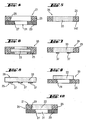
- FIGS. 1 to 3 An embodiment of the shoe stabilization material according to the invention will first be explained. This is followed by reference to the FIGS. 4 to 12 Explanations of embodiments of a barrier unit according to the invention. Based on FIGS. 13 to 29 Embodiments of the footwear according to the invention and shoe sole composites according to the invention will be explained.
- the in the FIGS. 1 to 3 illustrated embodiment of the invention shoe stabilization material consists of a fiber composite 1 in the form of a thermally bonded and additionally thermally surface-bonded nonwoven fabric.
- This fiber composite 1 consists of two fiber components 2, 3, which are each constructed, for example, with polyester fibers.
- a first fiber component 2 which serves as a carrier component of the fiber composite 1
- a higher melting temperature than the second fiber component 3 which serves as a solidification component.
- polyester polymers that have different melting temperatures and corresponding underlying softening temperatures.
- a polyester polymer having a melting temperature of about 230 ° C is selected for the first component, while a polyester polymer having a melting temperature of about 200 ° C is selected for at least one fiber portion of the second fiber component 3.
- the core 4 of this fiber component consists of a polyester having a softening temperature of about 230 ° C and the sheath of this fiber component is polyester having an adhesive softening temperature of about 200 ° C ( FIG. 2b ).
- Such a fiber component with two fiber portions of different melting temperature is also referred to as "bico" for short. In the following, this abbreviation will also be used.
- the fibers of the two fiber components are each staple fibers having the above-mentioned specific characteristics.
- the weight fraction of the first fiber component is about 50%.
- the weight fraction of the second fiber component is also about 50% based on the basis weight of the fiber composite 1.
- the fineness of the first fiber component is 6.7 dtex, whereas the bico second fiber component 3 has a higher fineness of 4.4 dtex.
- the fiber components present as staple fibers are mixed. Thereafter, a plurality of individual layers of this staple fiber mixture in the form of several individual nonwoven layers are placed on each other until the target weight of the fiber composite 1 is reached, whereby one arrives at a fleece package.
- This fleece package has very little mechanical stability and must therefore undergo some solidification processes.
- the fiber composite 1 according to the invention is further treated. It uses thermal energy and pressure.
- the advantageous composition of the fiber mixture is exploited, wherein for the thermal solidification of the fiber mixture is chosen such that it is at least in the range of the adhesive softening temperature of the lower melting temperature shell 5 of the core-shell bicos, to this extent in to soften a viscous state, that the fiber portions of the first fiber component, which are located in the vicinity of the softened mass of the jacket 5 of each Bicos, can be partially enclosed in this viscous mass.
- the two fiber components are permanently connected to each other, without changing the basic structure and structure of the nonwoven.
- the advantageous properties of this nonwoven fabric can be utilized, in particular its good water vapor permeability, combined with a permanent mechanical stabilizing property.
- FIG. 2 Such a thermally bonded nonwoven fabric is shown in a schematic representation in FIG. 2 shown in FIG. 2a a detailed view of a section on a greatly enlarged scale is shown, in which adhesive connection points between individual fibers are represented by flat black spots, and FIG. 2b shows an area of this section on an even larger scale.
- thermal surface compression may still be performed on at least one surface of the nonwoven material by simultaneously exposing this nonwoven material surface to pressure and temperature, for example by means of heated press plates or press rolls. The result is an even stronger solidification than in the remaining volume of the nonwoven material and a smoothing of the thermally pressed surface.
- FIG. 3 A nonwoven fabric which is mechanically consolidated by needling, then thermally consolidated and finally thermally surface pressed on one of its surfaces is in FIG. 3 shown schematically.
- the longitudinal strain values and the transverse strain values show by what percentage the respective material stretches when subjected to an expansion force of 50 N, 100 N or 150 N respectively.
- the puncture resistance is important.
- sole split leather has a high tensile strength, a relatively good resistance to stretching forces and a high puncture resistance, but that it has only a moderate abrasion resistance in wet samples and in particular a very moderate water vapor permeability.
- needle-bonded nonwoven materials material 2 and material 3
- material 2 and material 3 are relatively light and have a high water vapor transmission value compared to leather, they have a relatively low resistance to stretching forces, have only low puncture resistance and have only a moderate abrasion resistance.
- the needle-bonded and thermally bonded nonwoven fabric (material 4) has a smaller basis weight than the materials 2 and 3 and is therefore more compact.
- the water vapor permeability of the material 4 is higher than that of the material 2 and about the same as that of the material 3, but almost three times as large as that of the leather according to material 1.
- the longitudinal and transverse expansion resistances of the material 4 are significantly higher than those of only needle-bonded nonwoven materials 2 and 3, and the longitudinal and transverse load to break is also significantly higher than for the materials 2 and 3. Substantially higher than for the materials 2 and 3 are also the puncture resistance and abrasion resistance in material 4.
- the material 5, so needle-bonded, thermally bonded and thermally pressed on a surface nonwoven material has a smaller thickness than the material 4 due to the thermal fatiguenverpressung with the same basis weight, thus contributes less in a composite shoe sole.
- the water vapor permeability of the material 5 is still higher than that of the material 4.
- the material 5 is also superior to the material 4, since it shows no elongation at the applied longitudinal and transverse tensile forces of 50 N to 150 N.
- the tear strength is higher with respect to longitudinal load and lower than that of the material 4 in terms of transverse load.
- the puncture resistance is slightly below that of the material 4, which is caused by the smaller thickness of the material 5.
- a particular superiority over all materials 1 to 4 has the material 5 in terms of abrasion resistance.
- the comparison table thus shows that when it comes to shoe material to a high water vapor permeability, high dimensional stability and thus stabilizing effect and high abrasion resistance, the material 4, in particular the material 5 is quite particularly well suited.
- the needle-bonded and thermally bonded nonwoven which already has a very good stabilization, in one embodiment of the invention is then further subjected to a hydrophobing finish, for example by a dipping operation in a hydrophobizing liquid to minimize suction effects of the nonwoven material.
- a hydrophobing finish for example by a dipping operation in a hydrophobizing liquid to minimize suction effects of the nonwoven material.
- the nonwoven is dried under heat, whereby the hydrophobic property of the applied equipment is further improved.
- the nonwoven passes through a calibrator, whereby the final thickness of, for example, 1.5 mm is set.
- the nonwoven is then again subjected to temperature and pressure in order to remelt the fusible fiber components, namely in the jacket 5 of the bicomponent of the second fiber component, to the surface of the nonwoven fabric and with the aid of simultaneously applied pressure against a very smooth surface to press.
- a Trennmateriallage can be introduced, which is, for example, silicone paper or Teflon.
- the nonwoven thus produced has a high resistance to tearing load and has a good puncture resistance, which is important in the use of the shoe stabilization material as a barrier material for protecting a membrane.
- the material 5 described above represents a first embodiment of shoe stabilization material according to the invention, in which both fiber components are made of polyester, both fiber components have a weight percentage of 50% on the total fiber composite and the second fiber component is a polyester core-sheath fiber of Bico type acts.
- Shoe stabilization material in which both fiber components are made of polyester and have a weight percentage of 50% on the entire fiber composite and the second fiber component 3 is a bico of side-by-side polyester.
- the shoe stabilizing material according to Embodiment 2 is manufactured in the same manner and has the same properties as the shoe stabilizing material according to Embodiment 1 with a core-sheath type bico.
- Shoe stabilizing material in which both fiber components have a weight percentage of 50% each and the first fiber component 2 is made of polyester and the second fiber component 3 is made of polypropylene.
- the second fiber component 3 no bico but a monocomponent fiber is used.
- the polyester fiber having a melting temperature of about 230 ° C
- the carrier component while the polypropylene fiber with a weight fraction of 50% also has a lower melting temperature of about 130 ° C and thus the adhesive-capable solidification component represents.
- the manufacturing process otherwise proceeds as in the embodiment 1.
- the nonwoven according to Embodiment 3 has a lower thermal stability, but can also be produced using lower temperatures.
- Shoe stabilizing material containing 80% polyester as the first fiber component 2 and a polyester core-sheath bico as the second fiber component 3.
- the production is again as in the embodiment 1, but with the difference that the proportion of the hardening component forming second fiber component is changed.
- Their weight content is only 20% compared to 80% of the weight, which is formed by the higher-melting first fiber component 2.
- the stabilizing effect of the obtained shoe-stabilizing material is reduced. This can be advantageous if a nonwoven with high mechanical durability combined with increased flexibility is required.
- the temperature resistance of this nonwoven corresponds to that of the first embodiment.
- FIGS. 4 to 12 Now some embodiments of a shoe sole composite or a barrier unit or details thereof are considered.
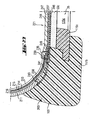
- FIG. 4 shows a partial cross-section through a composite shoe sole 21 with a lower sole 23 and a stabilizing device 25 located above before this shoe sole composite 21 is provided with a shoe stabilization material.
- the outsole 23 and the stabilizing device 25 each have passage openings 27 and 29, the total of an opening 31 form through the total thickness of the shoe sole composite 21.
- the opening 31 is thus formed by the sectional area of the two passage openings 27 and 29.
- shoe stabilization material 33 placed in the through hole 29 or arranged above this.
- FIG. 5 shows an example of a barrier unit 35 with a piece of shoe stabilization material 33, which is bordered by a stabilizer 25.
- the stabilizer is sprayed or sprayed around the length of shoe stabilizer material 33 such that the stabilizer material 25 penetrates and cures the fiber structure of the shoe stabilizer material 33 to form a strong bond.
- Thermoplastic polyurethane for example, which leads to a very good enclosure of the barrier material and bonds well with it, is suitable as the material for the encapsulation of the stabilization device or the injection molding onto the stabilization device.
- the shoe stabilization material 33 is adhered to the stabilizer 25.
- the stabilization device 25 preferably has a stabilizing frame 147 stabilizing at least the composite shoe sole 21.
- FIG. 6 shows a barrier unit 35, in which a piece of shoe stabilization material 33 is bordered by a stabilizer 25 in the sense that the edge region of the shoe stabilization material 33 is not only surrounded by the stabilizer 25, but also overlapped on both surfaces.
- FIG. 7 shows a barrier unit 35, in which a piece of stabilizing material 33 is enclosed by a stabilizer 25. At least one surface of the shoe stabilizing material 33 is provided with at least one stabilizing web 37 which at least partially traverses the surface of the opening. Preferably, the at least one stabilizing web 37 is arranged on a lower side, which is directed towards the outsole.
- FIG. 8 shows a barrier unit 35, in which a piece of shoe stabilization material 33 is provided with a stabilizing device 25 in the form of at least one stabilizing web 37.
- the stabilizing web 37 is arranged on at least one surface of the shoe-stabilizing material 33, preferably on the surface directed downwards towards the outsole 23.
- FIG. 9 1 shows a barrier unit 35 in which a piece of shoe stabilization material 33 is provided with a stabilizer 25 such that the shoe stabilizer material 33 is mounted on at least one surface of the stabilizer 25. In this case, the shoe stabilization material 33 covers the passage opening 29.
- FIG. 10 shows a composite shoe sole 21 according to FIG. 4 , the above the outsole 23 a barrier unit 35 according to FIG. 5 having.
- the bonding material during injection molding, encapsulation or gluing between stabilizing material 33 and stabilizer 25 not only adheres to the surfaces to be joined, but penetrates into the fiber structure and cures there.
- the fiber structure is additionally reinforced in their connection area.
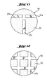
- FIGS. 11 and 12 Two embodiments of stabilizing web patterns 37 of stabilizing webs 37 applied to a surface of the shoe stabilizing material 33 are shown. While in the case of FIG. 11 on a circular surface 43 of the example underside of the shoe stabilizing material 33, which corresponds for example to an opening of the shoe sole composite 21, three individual webs 37a, 37b and 37c are arranged in a T-shaped mutual arrangement, for example by sticking to the underside of the shoe stabilization material 33, in the case of FIG. 12 a stabilization web 37 provided in the form of a stabilizing grid 37d.
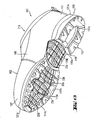
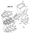
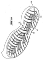
- FIG. 13 shows in perspective oblique view from below an embodiment of a shoe 101 according to the invention with a shaft 103 and a composite shoe sole 105.
- the shoe 101 has a forefoot portion 107, a midfoot portion 109, a heel portion 111 and a predominantlyeinschlüpfö réelle 113.
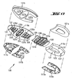
- the composite shoe sole 105 has on its underside a multi-part outsole 117, which has a outsole part 117a in the heel area, a outsole part 117b in the ball of the foot area and a outsole part 117c in the toe area of the composite shoe sole 105.
- outsole parts 117 are attached to the underside of a stabilizer 119 having a heel region 119a, a midfoot region 119b, and a forefoot region 119c.
- the composite shoe sole 105 will be explained in more detail with reference to the following figures.
- Further components of the composite shoe sole 105 may be damping sole parts 121 a and 121 b, which are applied in the heel region 111 and in the forefoot region 107 on the upper side of the stabilization device 119.
- the outsole 117 and the stabilizing device 119 each have passage openings which form openings through the composite shoe sole. These openings are covered by shoe stabilizing material parts 33a-33d in a water vapor permeable manner.
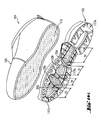
- Figure 14a shows the shoe 101 according to FIG. 13 in a manufacturing stage, in which the shaft 103 and the composite shoe sole 105 are still separated from each other.
- the shaft 103 is provided at its bottom-side lower end portion with a shaft bottom 115 having a waterproof, water vapor-permeable shaft bottom functional layer, which may be a waterproof, water vapor permeable membrane.
- the functional layer is preferably part of a multilayer functional layer laminate which, in addition to the functional layer, has at least one support layer, for example a textile side for processing protection.
- the shaft bottom 115 may be provided with a shaft mounting sole.
- the composite shoe sole has the already in FIG.
- openings 31 which are covered with shoe stabilization material parts 33a-33d.
- the webs 37 are shown within the peripheral edge of the respective openings. In further embodiments, three openings or two openings or an opening may be provided. In a another embodiment, more than four openings are provided.
- the composite shoe sole 105 may be attached to the sole-side shaft end either by injection molding or by gluing in order to obtain the state according to FIG FIG. 13 manufacture. For a detailed explanation of the functional layer and its laminate, and the connection with the mounting sole is on the description and the FIGS. 22 to 27 directed.
- FIG. 14b shows the same shoe structure as in Figure 14a , with the difference that the shoe is in Figure 14a has four openings 31, while the shoe after FIG. 14b equipped with two openings 31.
- the webs 37 are arranged within the peripheral edge of the respective aperture 31 and form no limitation of the aperture 31. The area of an opening is determined less the total area of the webs crossing it, since this land area blocks the transport of water vapor.
- FIG. 14c also shows the same shoe structure as in Figure 14a wherein the four apertures 31 in this embodiment are free of stabilizing webs 37.
- the openings 31 as well as in Fig. 14a and 14b be closed with one or more pieces of stabilizing material 33.
- FIG. 15 shows a composite shoe sole 105 with a top remote from the outsole 117 top.
- the stabilizer 119 is covered in its central portion 119b and in its forefoot portion 119c with a plurality of pieces 33a, 33b, 33c and 33d of a shoe-stabilizing material 33, with which FIG. 15 not visible openings of the shoe sole composite 105 are covered.
- a damping sole part 121a and 121b are respectively applied on the upper side of the stabilizing device 119, in the heel area substantially over the entire area and in the forefoot area with recesses where the shoe stabilizing material parts 33b, 33c and 33d are located.
- the outsole parts of the outsole 117, the stabilizer 119 and the damping sole parts 121 a and 121 b have different functions within the composite shoe sole, they are expediently constructed with different materials.
- the outsole parts which are to have a good abrasion resistance, for example, consist of an outsole material suitable thermoplastic polyurethane (TPU) or rubber.
- the damping sole parts 121 a and 121 b which are to cause a shock absorption in the walking movements for the user of the shoe, consist of correspondingly elastically yielding material, such as ethylene-vinyl acetate (EVA) or polyurethane (PU).
- the stabilization device 119 which serves as a support for the non-contiguous outsole parts 117a, 117b, 117c and for the likewise non-coherent damping sole parts 121a, 121b as a holder and for the entire shoe sole dressing 105 and should have a corresponding elastic stiffness, consists for example of at least a thermoplastic.
- suitable thermoplastics are polyethylene, polyamide, polyamide (PA), polyester (PET), polyethylene (PE), polypropylene (PP) and polyvinyl chloride (PVC).
- Other suitable materials are rubber, thermoplastic rubber (TR, from Thermoplastic Rubber) and polyurethane (PU). Also suitable is thermoplastic polyurethane (TPU).
- FIG. 15 Shoe sole composite shown is in FIG. 16 shown in exploded view, ie in a representation in which the individual parts of the shoe sole composite 105 are shown separately from each other, with the exception of the Schuhstabilmaschinesmaterialmaschine 33a, 33b, 33c and 33d, which are shown as already arranged on the Stabilmaschiness noticeds kind 119b and 119c.
- the stabilizing device 119 has its parts 119a, 119b and 119c as initially separate parts, which are connected to one another in the course of assembly of the shoe sole composite 105 to the stabilizing device 119, which can be done by welding or gluing the three stabilizer parts together.
- FIG. 16 shown in exploded view, ie in a representation in which the individual parts of the shoe sole composite 105 are shown separately from each other, with the exception of the Schuhstabilmaschinesmaterialmaschine 33a, 33b, 33c and 33d, which are shown as already arranged on the Stabilmaschiness noticed 119b and 119c.
- a passage opening 125 in the heel part 119 a of the stabilization device 119 is not closed with shoe stabilization material 33 but with the full-surface damping sole part 121 a. This achieves a better damping effect of the composite shoe sole 105 in the heel region of the shoe, where perspiration moisture removal may under certain circumstances be less necessary since foot perspiration forms predominantly in the forefoot and midfoot region, but not in the heel region.
- the cushioning sole portion 121b is provided with through holes 127a, 127b and 127c dimensioned so that the shoe stabilizing material portions 33b, 33c, 33d surrounding boundary edges 129a, 129b and 129c of the stabilizer portion 119c can be received in the through holes 127a, 127b and 127c, respectively.
- the parts of the stabilizer 119a, 119b and 119c have a planar surface without a delimiting edge 129a, 129b, 129c, so that the stabilizing material 33 is placed flush with the surface of the stabilizer in its openings.
- the sole composite is formed only by the barrier unit constructed of shoe stabilizing material 33 and the stabilizer 119, and the outsole.
- FIG. 16 shoe sole composite parts 105 shown obliquely above are shown in FIG. 17 also shown in a separate arrangement, but in an oblique view from below.
- the outsole parts 117a to 117c are provided in the usual way with an outsole profile in order to reduce the risk of slipping.
- the undersides of the stabilizer means 119a and 119c have on their underside a plurality of knob-like projections 131 which are adapted to receive in FIG. 16 to see complementary recesses 133 in the tops of the outsole parts 117a, 117b and 117c for positionally correct connection of the outsole parts 117a to 117c with the associated Stabilmaschines Rheins kind 119a and 119c serve.
- openings 135a, 135b, 135c and 135d can be seen in the stabilizer means 119b and 119c which are covered with the respective shoe stabilization material part 33a, 33b, 33c and 33d in a water vapor permeable manner, whereby the openings 31 (FIG. FIG. 4 ) of the composite shoe sole 105 are closed in a way permeable to water vapor.
- the shoe stabilization material parts are arranged with their smooth surface facing the outsole.
- the openings 135a to 135d are each bridged with a stabilizing grid 137a, 137b, 137c and 137d, which each form a stabilizing structure in the region of the respectively associated opening of the stabilizing device 119.
- these stabilizing gratings 137a-137d act against the penetration of larger foreign objects up to the shoe stabilizing material 33 or beyond, which could be unpleasantly felt by the user of the shoe.
- the barrier unit is additionally designed as an outsole with an outsole profile.
- connecting elements 139 provided at the axial ends of the stabilizer device part 119b on the middle side which, when the stabilizer 119 is assembled from the three stabilizer parts 119a to 119c, overlap on the upper sides of the stabilizer parts 119a and 119c facing away from the outsole side to be, for example, by Verschwei- hybrid or bonding.
- FIG. 18 shows in opposite FIG. 17 enlarged representation of the two stabilizing device parts 119c and 119b before their attachment to each other, the openings 135b to 135d of the forefoot stabilization device part 119c and the stabilizing grid structures therein are particularly well visible.
- the middle stabilization device part 119b shows bent-up frame and lattice parts on the longitudinal sides.
- the shoe stabilizing material piece 33a to be placed on the stabilizing device part 119b is provided on its longitudinal sides with correspondingly curved side wings 141.
- FIG. 19 shows another embodiment of the forefoot portion 107 and the midfoot portion 109 according to FIG. 17 ,
- the stabilizer 119 is formed without stabilizing webs 37.
- the surface of the stabilizing material 33 terminates flush with the surface of the stabilizing device 119.
- the openings 135 ad are each provided with circumferential support projections 150 for receiving the stabilizing material 33, so that it can be fitted into the openings 135 ad.
- the at least one opening 135 a-135d of the stabilizer 119b and 119c is bounded by the frame 147 of the stabilizer 119 and not by possibly present webs 37 in the openings 135a-135d.
- limiting edges 129 a-129c represent in this embodiment, a part of the respective frame 147.
- FIGS. 20 and 21 Another modification of the barrier foot portion provided with the stabilizer portion 119b and the shoe stabilizing material portion 33a is provided in FIGS FIGS. 20 and 21 shown in FIG. 20 in the assembled state and in FIG. 21 while these two parts are still separated.
- the stabilization device part 119b provided for the midfoot area is provided only in the central area with an opening and a stabilizing grid 137a therein, while the two wing parts 143 are continuous on the longitudinal sides of the stabilizing device part 119b, ie they have no opening but only on their underside with stabilizing ribs 145 are provided.
- the shoe stabilizing material piece 33a provided for this barrier unit part is narrower than in the variants of FIGS Figures 18 and 19 because it is not the side wings 141 according to the Figures 18 and 19 needed.
- FIGS 22 to 29 is constructed with a composite shoe sole according to the invention.
- the show Figures 22 . 24 and 25 an embodiment of the footwear according to the invention, in which the shaft bottom 221 has a shaft mounting base 233 and additionally a functional layer laminate 237, while the Figures 26 and 27 show an embodiment of footwear according to the invention, in which a Schaftêtfunktions slaughterlamintechnik 237 simultaneously the function of a shaft mounting base 233 takes over.
- the FIG. 28 shows a further embodiment of the shoe sole composite 105th
- the shoe 101 in accordance with the Figures 13 and 14 a - c has a shank 103, which has an outer material layer 211 on the outside, an inner lining layer 213 and a waterproof, water vapor permeable, shank functional layer layer 215 located therebetween, for example in the form of a membrane.
- the shank functional layer layer 215 may be in composite with the lining layer 213 as a 2-ply laminate or as a 3-ply laminate with the sheath-functional layer layer 215 embedded between the lining ply 213 and a textile downside 214.
- the upper shank end 217 is depending on whether the cutting plane in the Figures 22 and 26 illustrated cross-sectional view in the forefoot or midfoot area, closed or additionallyeinschlüpfö réelle 113 (Figure 13) open.
- the shaft 103 is provided with a shaft bottom 221, with which the sole-side lower end of the shaft 103 is closed.
- the shaft bottom 221 has a shaft mounting sole 233 which is connected to the sole side shaft end portion 219, which in the embodiments according to FIGS FIGS. 22 to 27 done by means of a Strobelnaht 235.
- a shaft bottom functional layer laminate 237 disposed below the shaft mounting sole 233 and extending beyond the circumference of the shaft mounting sole 233 to the sole side shaft end region 219.
- the shaft bottom functional layer laminate 237 may be a 3-layer laminate, with the shaft bottom functional layer 247 is embedded between a textile side and a further textile layer. It is also possible to provide the Schaftêtfuntions Mrs 247 only with the textile side.
- the upper material layer 211 is shorter than the shank functional layer layer 215, so that there is provided a projection of the shank functional layer layer 215 opposite the upper material layer 211 and the outer surface of the shank functional layer layer 215 is exposed there.
- a mesh 241 or other material permeable to sealing material is arranged between the sole side end 238 of the upper material layer 211 and the sole end 239 of the shaft functional layer layer 215.
- the mesh band 241 is preferably made of a monofilament material so that it has no water conductivity.
- the mesh band is preferably used for injection-molded soles. If the sole composite is attached to the shaft by means of adhesive, instead of the mesh belt, the sole-side end 238 of the upper material layer 211 can be fastened by means of adhesive 249 to the Zwickschaftfunktions slaughterlaminat ( FIG. 24 ).
- a sealing material 248 is arranged between the shaft bottom functional layer laminate 237 and the sole end 239 of the shaft functional layer layer 215, by means of which a watertight connection between the sole end 239 of the shaft functional layer layer 215 and the peripheral portion 245 of the shaft bottom functional layer laminate 237 is made, this seal acts through the net 241 therethrough.
- net band solution serves to prevent water that runs down or creeps on the Obermateriallage 211, reaches the Strobelnaht 235 and penetrates from there into the shoe interior. This is prevented by the fact that the sole-side end 238 of the upper material layer 211 terminates at a distance from the sole-side end 239 of the shaft functional layer layer 215, which is bridged with the non-water-conducting net 241, and in the region of the supernatant of the Schaftfunktions harshlage 215, the sealing material 248 is provided.
- the network tape solution is known per se from the document EP 0298360 B1 ,
- connection technologies used in the shoe industry can be used for preferably watertight connection of the shaft to the shaft bottom.
- the illustrated mesh tape solution in the Figures 22 . 25-27 and the nipped solution in FIG. 24 are exemplary embodiments.
- FIG. 26 shown shaft construction is consistent with the in FIG. 22 shown shaft construction, with the exception that there is no separate shaft mounting base 233 is provided, but that the Schaftêtfunktions Anlagenlaminat 237 simultaneously assumes the function of a shaft mounting base 233 with. Accordingly, the circumference of the shaft bottom functional layer laminate 237 is that in FIG FIG. 26 in the region of this strobe seam 235 so that the transition between the sole-side end 239 of the shank functional layer layer 215 and the peripheral region of the shank bottom functional layer laminate 237 is completely sealed, including the strobe seam 235.
- the sectional view of the shoe sole composite 105 shows the stabilizer device part 119c with its opening 135c, a bridge of the associated stabilizing grid 137c bridging this opening, the upwardly upstanding boundary edge 129b, the shoe stabilizing material piece 33c inserted in this limiting edge 129b, the damping sole part 121b on the upper side the stabilizer portion 119c and the outsole portion 117b on the underside of the stabilizer portion 119c.
- both embodiments of the agree Figures 22 and 26 match.
- FIG. 23 shows an example of a barrier unit 35, in which a piece of shoe stabilization material 33 is provided on its underside with at least one stabilizing web 37.
- an adhesive 39 is applied, via which the shoe stabilizing material 33 is connected to the waterproof, water vapor permeable shaft bottom 221, which is located outside of the composite shoe sole above the barrier unit 35.
- the adhesive 39 is applied in such a way that the shaft bottom 221 remains unconnected to the shoe stabilizing material 33 wherever it abuts the underside of the shoe stabilizing material 33 no material of the stabilizing web 37 is located. In this way, it is ensured that the water vapor permeability function of the shaft bottom 115 is disturbed by adhesive 39 only where the shoe stabilizing material 33 can not allow any water vapor transport anyway due to the arrangement of the stabilizing web 37.
- the shaft bottom functional layer 247 of the shaft bottom functional layer laminate 237 in all embodiments is preferably a microporous functional layer, for example of stretched polytetrafluoroethylene (ePTFE).
- ePTFE stretched polytetrafluoroethylene
- FIG. 24 shows an embodiment in which the composite sole 105 according to the invention is attached by means of fastening adhesive 250 on the shaft bottom 221.
- the sheath functional layer laminate 216 is a three-layer composite having a fabric layer 214, a shank functional layer 215, and a liner 213.
- the sole-side end 238 of the topsheet 211 is attached to the sheath-functional layer laminate 216 with pinch adhesive 249.
- the fastening adhesive 250 is applied flat on the surface of the composite sole with the exception of the perforations 135c and the shoe stabilizing material 33c arranged in the region of the perforations 135c.
- the attachment adhesive 250 penetrates up to and partially into the shaft functional layer laminate 216 and at and partially into edge regions of the shaft bottom functional layer laminate 237.
- FIG. 25 is an illustration of the shaft structure according to FIG. 22 with a molded soles composite.
- the three-ply shaft bottom functional layer laminate 237 is attached to the shaft mounting base 233 such that the textile side 246 points to the composite sole. This is advantageous because the sole spray 260 may more readily penetrate and anchor into the thin textile backing, thus providing a strong bond to the shaft bottom functional layer 237.
- the barrier unit with the at least one opening 135c and the at least one piece of shoe stabilization material 33c is present as a prefabricated unit and is inserted into the injection mold before the injection process.
- the sole injection material 260 is correspondingly injection molded onto the shaft bottom, penetrating through the net 241 to the shaft functional layer laminate 216.
- FIG. 27 shows an enlarged and fragmentary view of FIG. 26
- the sole compound 105 shows a further embodiment of the barrier unit 35 according to the invention.
- the shoe stabilizer 119c forms part of the sole composite 105 and does not extend to the outer periphery of the sole composite 105.
- a piece of shoe stabilizing material 33c is attached so that the material 33c rests on the peripheral continuous plan shaped boundary edge 129 of the opening 135c.
- the sole composite 105 can be fastened with attachment adhesive 250 on the shaft bottom 221 or sprayed with sole injection material 260.
- FIG. 27 also clearly shows that in the embodiment in which the shaft bottom functional layer laminate 237 takes over the function of the shaft mounting sole, laminate immediately above the opposite top of the shoe stabilization material piece 33c comes to rest, which is particularly advantageous.
- the shaft bottom functional layer laminate 237 and the shoe stabilizing material piece 33c there can not form an air cushion which might impair the water vapor removal, and the shoe stabilizing material piece 33c and especially the shaft bottom functional layer 247 are particularly close to the foot sole of the user of such shoe, facilitating water vapor removal which is co-determined by the existing temperature gradient between shoe interior and shoe exterior.
- the composite shoe sole 105 and the shaft 103 are provided, wherein the sole-side lower region of the shaft can still be open.
- the shank 103 is provided at its sole-side shank end portion 219 with a shank bottom 221 formed by either the shank-bottom-function-layer laminate 237 or such shank-bottom-function-layer laminate 237 and a separate shaft-mounting sole 233.
- a shaft provided with a shaft bottom functional layer laminate 237 from the beginning in the sole side shaft end portion 219 may be provided.
- the composite shoe sole 105 is attached to the sole side shaft end 219, which can be done either by gluing the shoe sole composite 105 with the lower shaft end by means of an adhesive 250 or by a shoe sole composite 105 is molded onto the underside of the shaft.
- the connection between the lower shaft end and composite shoe sole 105 occurs such that the shaft bottom functional layer 239 remains unconnected to the shoe stabilizing material 33c of the shaft bottom composite 221 at least in the region of the openings of the composite shoe sole 105.
- FIG. 28 is an illustration of another embodiment of the composite sole according to the invention.
- the perspective view shows a plurality of openings 135 in the shoe stabilizer 119, which are arranged from the toe area to the heel area of the composite sole.
- the stabilizing material 33 is also present in the heel area.
- FIG. 29 is a representation of another embodiment of the composite sole according to the invention in cross-sectional view.
- the sole composite 105 of this embodiment is the in FIG. 26 Similar to the soles shown.
- the sole composite 105 according to FIG. 29 has an outsole, wherein in this figure a cross section through the ball of the foot region of the composite sole 105 is shown and therefore a cross section through the corresponding outsole part 117b.
- the teaching according to FIG. 29 But also applies to the other areas of the composite sole 105, so also for the foot middle part and the heel part.
- the outsole part 117b has a tread 153, which committed while running the Ground touched.
- the stabilizing device part 119c with its opening 135c, its upwardly upstanding boundary edge 129b, the shoe stabilizing material piece 33c inserted into the limiting edge 129b, the damping sole part 121b on the upper side of the stabilizer part 119c and the sole part 117b on the lower side of the stabilizer part 119c.
- a supporting member 151 is attached at the bottom of the shoe stabilizing material piece 33c. This extends from the tread-facing side of the shoe-stabilizing material 33 to the level of the tread 153, such that the shoe-stabilizing material 33 is supported when running on the support member 151 on the ground committed. That means that an in FIG.
- a plurality of support members 151 may be arranged to increase the support action for the shoe stabilizing material piece 33c and to make more uniform over the surface extension thereof.
- the support function can also be obtained by using the in FIG. 26 stabilizing web 137c shown at the same time forms as a support member 151 by the stabilizer bar 137c can not end at a distance from the underside of the outsole part 117b serving as a running surface but extended to the level of this underside.
- the stabilizing land 137c is given the dual function of stabilizing and supporting the shoe stabilizing material piece 33c.
- the in FIG. 11 stabilizing webs 37c or the stabilizing grid 37d shown in FIG. 12 are formed entirely or partially as supporting elements 151.
- a high water vapor permeability value is achieved because large openings are provided in the composite shoe sole 105 and these are closed with material of high water vapor permeability and because also at least in the area of the openings no water vapor exchange obstructing connection between the water vapor permeable shoe stabilizing material 33 and the shank bottom functional layer is and such a compound is present at most in the areas outside the apertures of the shoe sole composite 105, which are not actively involved in water vapor exchange, such as the edge regions of the shoe sole composite 105.
- the shaft bottom functional layer is arranged close to the foot in the structure according to the invention, which leads to accelerated water vapor removal.
- Shaft bottom functional layer laminate 237 may be a multilayer laminate having two, three, or more layers. Contained is at least one functional layer with at least one textile support for the functional layer, wherein the functional layer can be formed by a waterproof, water vapor permeable membrane 247, which is preferably microporous.
- the thickness of the shoe stabilization material according to the invention is tested according to DIN ISO 5084 (10/1996).
- the puncture resistance of a fabric can be measured with a measuring method used by the EMPA (Swiss Federal Laboratories for Materials Testing and Research) using a testing machine of the Instron tensile testing machine (model 4465).
- EMPA Error tensile testing machine
- a punching iron By means of a punching iron, a round textile piece with a diameter of 13 cm is punched out and fastened on a support plate in which there are 17 holes.
- the force for piercing the textile piece is measured by means of a load cell (a force transducer). The result is determined from a sample number of three samples.
- a functional layer is considered to be "waterproof", if appropriate including seams provided on the functional layer, if it ensures a water inlet pressure of at least 1x10 4 Pa.
- the functional layer material ensures a water inlet pressure of over 1x10 5 Pa.
- the water inlet pressure shall be measured by a test method in which distilled water is applied at 20 ⁇ 2 ° C to a sample of 100 cm 2 of the functional layer with increasing pressure. The pressure increase of the water is 60 ⁇ 3 cm Ws per minute. The water inlet pressure then corresponds to the pressure at which water first appears on the other side of the sample. Details of the procedure are specified in the ISO standard 0811 from the year 1981.
- Whether a shoe is waterproof for example, with a centrifuge assembly in the US-A-5,329,807 be tested type tested.
- the water vapor permeability values shoe stabilization material according to the invention are tested using the so-called cup method according to DIN EN ISO 15496 (09/2004).
- a functional layer As a "water vapor permeable" a functional layer is considered, if it has a water vapor transmission rate Ret of less than 150 m2 ⁇ Pa ⁇ W -1 .
- the water vapor permeability is tested according to the Hohenstein skin model. This test method is described in DIN EN 31092 (02/94) or ISO 11092 (1993).
- the shoe bottom structure has a Moisture Vapor Transmission Rate (MVTR) in the range of 0.4 g / h to 3 g / h , which may range from 0.8 g / h to 1.5 g / h, and in one practical embodiment is 1 g / h.
- MVTR Moisture Vapor Transmission Rate
- the degree of water vapor permeability of the shoe bottom structure can be compared with that in the document EP 0396716 B1 determined measurement method, which has been designed to measure the water vapor permeability of an entire shoe.
- the measuring method according to EP 0 396 716 B1 also be used by with the in Fig. 1 of the EP 0 396 716 B1 the measurement setup shown is measured in two consecutive measurement scenarios, namely once the shoe with a water vapor permeable shoe bottom construction and another time the otherwise identical shoe with a water vapor-resistant shoe bottom construction. From the difference between the two measured values then the proportion of water vapor permeability can be determined, which goes back to the water vapor permeability of the water vapor permeable shoe bottom structure.
- abrasion resistance for the abrasion measurements for obtaining the abrasion values in the comparative table
- two measuring methods have been used.
- testing was carried out with a Martindale abrasion tester (in the table "Abrasion Carbon") in which according to the standard DIN EN ISO 124947-1; -2; (04/1999) scrubbed the sample to be tested against sandpaper.
- grit 180 plus standard foam was clamped in the sample holder.
- standard felt plus the test specimen were clamped in the sample table.
- the sample was inspected every 700 tours and the sandpaper replaced.
- Lissajous figures represent a periodically repeating overall picture with a suitable choice of the ratio of the frequencies involved, which is composed of relatively individual figures.
- the passage through one of these individual figures is referred to as a tour in the context of the abrasion test.
- a tour in the context of the abrasion test.
- the comparison table there are two tour values for each of the materials, which were created from two abrasion tests each with the same material.
- the hardness according to Shore is the resistance to the penetration of a certain shape of a body under a defined spring force.
- the Shore hardness is the difference between the numerical value 100 and the indentation depth of the indenter divided by the scale value 0.025 mm in mm under the effect of the test load.
- a truncated cone with an opening angle of 35 ° is used as the indenter, and in Shore D a cone with an opening angle of 30 ° and a tip radius of 0.1 mm.
- the indenters are made of polished, hardened steel.
- materials with a Shore A hardness> 80 should be suitably tested to Shore D and materials with a Shore D hardness ⁇ 30 to Shore A.
- Material which is associated with the shoe (s) / materials present in the shoe such as the upper, sole, membrane, mechanical protection and resistance to deformation, as well as the penetration of external objects / foreign bodies / objects e.g. through the sole allows, while maintaining a high water vapor transport, i. a high climate comfort in the shoe.
- the mechanical protection and resistance to deformation is mainly due to the low elongation of the shoe stabilizer material.
- the fiber composite must have at least two fiber components. These components may be fibers (eg, staple fibers), filaments, fiber elements, yarns, strands, and the like. act. Each fiber component is either made of one material or contains at least two different proportions of material, one of which softens / melts at a lower temperature than the other fiber portion (Bico). Such bico-fibers may have a core-shell structure - here a core fiber portion is sheathed with a sheath fiber portion - having a side-by-side structure or an islands-in-the-sea structure. Such processes and machines are available from Rieter Ingolstadt, Germany and / or Schalfhorst in Mönchengladbach, Germany. The fibers can be simply spun, multifilament, or multiple ruptured fibers with intertwined frayed ends. The fiber components can be distributed uniformly or unevenly in the fiber composite.
- the entire fiber composite must preferably be temperature stable at least 180 ° C.
- a uniform and smooth surface on at least one side of the fiber composite is achieved by means of pressure and temperature. This smooth surface shows "down" to the ground / floor, thus ensuring that the smooth surface particles / foreign bodies bounce off better or are easily rejected.
- the properties of the surface or of the overall structure of the fiber composite or stabilizing material depend on the fibers selected, the temperature, the pressure and the time over which the fiber composite was subjected to temperature and pressure.
- the fibers are deposited on a conveyor belt and confused.
- Sheets made with warp and weft threads made with warp and weft threads.
- the melting temperature is the temperature at which the fiber component or portion becomes liquid. In the field of polymer or fiber structures, the melting temperature is understood to be a narrow temperature range in which the crystalline regions of the polymer or fiber structure melt and the polymer changes to the liquid state. It is above the softening temperature range and is an essential parameter for semicrystalline polymers. Melted is the change in the state of aggregation of the fiber or parts of the fiber at a characteristic temperature of too viscous / flowable.
- the second fiber component or the second fiber portion must only be soft / plastic, but not liquid. That the softening temperature used is below the melting temperature at which the component / fraction dissolves.
- the fiber component or parts thereof are softened such that the more temperature-stable component is embedded in the softened parts.
- the first softening temperature range of the first fiber component is higher than the second softening temperature range of the second fiber component or the second fiber portion of the second fiber component.
- the lower limit of the first softening range may be below the upper limit of the second softening range.
- the adhesive softening temperature can also be chosen so that a softening of the fibers of the second fiber component takes place to such an extent that an adhesion not only of fibers of the second fiber component with each other but also a partial or total sheathing of individual points of the fibers of the first fiber composite with softened material
- the fibers of the second fiber composite arises, so a partial or total embedding such locations of fibers of the first fiber composite in the material of fibers of the second fiber component, that a correspondingly increased stabilization solidification of the fiber composite arises.
- the shoe stabilizer material must be temperature stable for injection molding. The same applies to injection molding (about 170 ° C - 180 ° C) or vulcanization of the shoe sole. If the stabilizing device is to be injection-molded, the shoe stabilizing material must have a structure such that the stabilizing device can at least penetrate into the structure of the shoe-stabilizing material or, if appropriate, penetrate it.
- the shaft bottom functional layer and optionally the shaft functional layer may be formed by a waterproof, water vapor permeable coating or by a waterproof, water vapor permeable membrane, which may be either a microporous membrane or a nonporous membrane.
- the membrane comprises stretched polytetrafluoroethylene (ePTFE).
- Suitable materials for the waterproof, water-vapor-permeable functional layer are in particular polyurethane, polypropylene and polyester, including polyether esters and their laminates, as described in the publications US-A-4,725,418 and US-A-4,493,870 are described.
- stretched microporous polytetrafluoroethylene ePTFE
- ePTFE stretched microporous polytetrafluoroethylene
- a microporous functional layer is understood to be a functional layer whose average pore size is between about 0.2 ⁇ m and about 0.3 ⁇ m. The pore size can be measured with the Coulter Porometer (trade name) manufactured by Coulter Electronics, Inc., Hialeath, Florida, USA.
- the barrier unit is formed by the shoe stabilization material and optionally by the stabilization device in the form of at least one web and / or a frame.
- the barrier unit may be in the form of a prefabricated component.
- the composite shoe sole consists of shoe stabilizing material and at least one stabilizing device and / or at least one outsole and possibly further sole layers, the shoe stabilizing material closing the at least one opening extending through the composite shoe sole thickness.
- An opening is the area of the composite shoe sole through which water vapor transport is possible.
- the outsole and the stabilizing device each have passage openings, which together form an opening through the total thickness of the composite shoe sole.
- the opening is thus formed by the sectional area of the two passage openings. Possibly existing webs are arranged within the peripheral edge of the respective opening and form no limitation of the opening.
- the area of an opening is determined less the area of all webs crossing it, since this land area blocks the transport of water vapor and thus does not constitute a breakthrough area.
- the stabilizer acts as additional stabilization of the shoe stabilizer material, is shaped and attached to the shoe stabilizer material such that the water vapor transmission rate of the shoe stabilizer material is only marginally affected, if at all. This is achieved by covering only a small area of the shoe-stabilizing material with the stabilizing device.
- the stabilizer is directed down to the ground.
- the stabilization device is not a protective function but a stabilization device.
- the at least one opening of the stabilization device is limited by its at least one frame.
- the area of an opening is determined less the area of all webs crossing it.
- Footwear consisting of a composite shoe sole and a closed top (shaft).
- the shoe bottom covers all layers below the foot.
- the thermal activation takes place by applying energy to the fiber composite, which leads to an increase in the temperature of the material up to the softening temperature range.
- Tested is a composite shoe sole according to centrifuge arrangement in the US-A-5,329,807 Before testing it must be ensured that a possibly existing shaft bottom functional layer is made permeable to water. From a water-permeable composite shoe sole one goes off if this test is failed. Optionally, the colored liquid test is performed to identify the path of the fluid through the composite shoe sole.
- Laminate is a composite consisting of a waterproof, water vapor permeable functional layer with at least one textile layer.
- the at least one textile layer also called the side, serves mainly to protect the functional layer during its processing.
- This is called a 2-layer laminate.
- a 3-layer laminate consists of a waterproof, water-vapor-permeable functional layer, which is embedded between two textile layers, wherein a point-like adhesive can be applied between these layers.
- a functional layer is considered to be "waterproof”, if appropriate including seams provided on the functional layer, if it ensures a water inlet pressure of at least 1x10 4 Pa.
- Outsole means the part of the composite shoe sole that touches the ground / subfloor or makes the main contact with the ground / subfloor:
Landscapes
- Engineering & Computer Science (AREA)
- Textile Engineering (AREA)
- Mechanical Engineering (AREA)
- Health & Medical Sciences (AREA)
- Epidemiology (AREA)
- General Health & Medical Sciences (AREA)
- Public Health (AREA)
- Chemical & Material Sciences (AREA)
- Materials Engineering (AREA)
- Footwear And Its Accessory, Manufacturing Method And Apparatuses (AREA)
Priority Applications (1)
| Application Number | Priority Date | Filing Date | Title |
|---|---|---|---|
| PL07723014T PL1991728T3 (pl) | 2006-03-03 | 2007-03-02 | Materiał do stabilizacji butów i zmontowana za jego pomocą wyściółka, zespolenie zelówki i obuwie |
Applications Claiming Priority (4)
| Application Number | Priority Date | Filing Date | Title |
|---|---|---|---|
| DE102006009974A DE102006009974A1 (de) | 2006-03-03 | 2006-03-03 | Schuhstabilisierungsmaterial, Barriereeinheit, Schuhsohlenverbund und Schuhwerk |
| DE202006018138U DE202006018138U1 (de) | 2006-03-03 | 2006-11-29 | Schuhstabilisierungsmaterial, Barriereeinheit, Schuhsohlenverbund und Schuhwerk |
| DE202007000668U DE202007000668U1 (de) | 2006-03-03 | 2007-01-17 | Schuhsohlenstabilisierungsmaterial |
| PCT/EP2007/001819 WO2007101624A1 (de) | 2006-03-03 | 2007-03-02 | Schuhstabilisierungsmaterial und aufgebaut damit barriereeinheit, schuhsohlenverbund und schuhwerk |
Publications (2)
| Publication Number | Publication Date |
|---|---|
| EP1991728A1 EP1991728A1 (de) | 2008-11-19 |
| EP1991728B1 true EP1991728B1 (de) | 2013-01-23 |
Family
ID=37913367
Family Applications (1)
| Application Number | Title | Priority Date | Filing Date |
|---|---|---|---|
| EP07723014A Not-in-force EP1991728B1 (de) | 2006-03-03 | 2007-03-02 | Schuhstabilisierungsmaterial und aufgebaut damit barriereeinheit, schuhsohlenverbund und schuhwerk |
Country Status (12)
| Country | Link |
|---|---|
| US (1) | US8312644B2 (enExample) |
| EP (1) | EP1991728B1 (enExample) |
| JP (1) | JP5086279B2 (enExample) |
| KR (1) | KR101229018B1 (enExample) |
| AU (1) | AU2007222643B2 (enExample) |
| CA (1) | CA2644526C (enExample) |
| DE (1) | DE202007000668U1 (enExample) |
| DK (1) | DK1991728T3 (enExample) |
| ES (1) | ES2404287T3 (enExample) |
| NO (1) | NO20083796L (enExample) |
| PL (1) | PL1991728T3 (enExample) |
| WO (1) | WO2007101624A1 (enExample) |
Cited By (4)
| Publication number | Priority date | Publication date | Assignee | Title |
|---|---|---|---|---|
| US11744322B2 (en) | 2018-05-08 | 2023-09-05 | Puma SE | Sole of a shoe, particularly an athletic shoe |
| US11926115B2 (en) | 2018-05-08 | 2024-03-12 | Puma SE | Method for producing a sole of a shoe, in particular of a sports shoe |
| US12109775B2 (en) | 2021-12-22 | 2024-10-08 | Puma SE | Method for producing a sole of a shoe |
| US12478134B2 (en) | 2019-10-21 | 2025-11-25 | Puma SE | Article of footwear |
Families Citing this family (37)
| Publication number | Priority date | Publication date | Assignee | Title |
|---|---|---|---|---|
| JP2562819B2 (ja) * | 1987-08-12 | 1996-12-11 | パイオニア株式会社 | ラジオデータ受信機 |
| EP3001922B1 (de) | 2006-03-03 | 2020-05-27 | W.L. Gore & Associates GmbH | Schuhsohlenverbund, damit aufgebautes schuhwerk und verfahren zu dessen herstellung |
| DE102006010007A1 (de) * | 2006-03-03 | 2007-09-06 | W.L. Gore & Associates Gmbh | Schuhsohlenverbund und damit aufgebautes Schuhwerk |
| DE102006009974A1 (de) * | 2006-03-03 | 2007-09-06 | W.L. Gore & Associates Gmbh | Schuhstabilisierungsmaterial, Barriereeinheit, Schuhsohlenverbund und Schuhwerk |
| DE102008027856A1 (de) | 2008-06-11 | 2009-12-24 | W. L. Gore & Associates Gmbh | Schuh mit Belüftung im unteren Schaftbereich und dafür verwendbares luftdurchlässiges Abstandsgebilde |
| DE202008009455U1 (de) * | 2008-06-20 | 2009-08-06 | W. L. Gore & Associates Gmbh | Sohleneinheit für Schuhwerk |
| NZ706870A (en) * | 2008-12-10 | 2016-11-25 | Resmed Ltd | Headgear for masks |
| IT1392520B1 (it) * | 2008-12-22 | 2012-03-09 | Geox Spa | Struttura di calzatura impermeabile e traspirante |
| US20100199406A1 (en) * | 2009-02-06 | 2010-08-12 | Nike, Inc. | Thermoplastic Non-Woven Textile Elements |
| DE102009015890A1 (de) | 2009-04-01 | 2010-10-14 | W. L. Gore & Associates Gmbh | Sohleneinheit für Schuhwerk und damit versehenes Schuhwerk |
| IT1395121B1 (it) * | 2009-07-29 | 2012-09-05 | Lenzi Tecnologie S R L | Soletta modulare per calzature ed inserto modulare per capi di abbigliamento |
| US20110067272A1 (en) * | 2009-09-23 | 2011-03-24 | Wen-Shan Lin | Ventilative pu midsole or sole pad |
| DE102010006150A1 (de) * | 2010-01-29 | 2011-08-04 | W. L. Gore & Associates GmbH, 85640 | Schaftanordnung für Schuhwerk sowie Schuhwerk damit |
| IT1398094B1 (it) * | 2010-02-10 | 2013-02-07 | Geox Spa | Calzatura con tomaia e suola impermeabili |
| DE102010044260A1 (de) * | 2010-09-03 | 2012-03-08 | Ecco Sko A/S | Schaftanordnung für Schuhwerk sowie Schuhwerk damit |
| KR101737163B1 (ko) | 2010-09-03 | 2017-05-17 | 더블유.엘.고어 앤드 어소시에이츠 게엠베하 | 신발, 신발용 밑창 조립체, 밑창 조립체 제조 방법, 및 신발 제조 방법 |
| USD635753S1 (en) * | 2010-11-04 | 2011-04-12 | Deckers Outdoor Corporation | Footwear outsole |
| USD634527S1 (en) * | 2010-11-08 | 2011-03-22 | Deckers Outdoor Corporation | Footwear outsole |
| US9150986B2 (en) | 2011-05-04 | 2015-10-06 | Nike, Inc. | Knit component bonding |
| US20120311887A1 (en) * | 2011-06-10 | 2012-12-13 | Peter Wong | Therapeutic Shoe Sole and Methods of Manufacturing the Same |
| WO2013017155A1 (en) * | 2011-07-29 | 2013-02-07 | W. L. Gore & Associates Gmbh | Upper assembly for footwear and footwear including the same |
| US20130061496A1 (en) * | 2011-09-08 | 2013-03-14 | Kevin B. Lawlor | Footwear support structures |
| USD672124S1 (en) * | 2012-08-31 | 2012-12-11 | Nike, Inc. | Shoe outsole |
| CN105188444B (zh) * | 2013-03-13 | 2017-12-12 | Tbl许可有限责任公司 | 安全鞋 |
| USD697297S1 (en) * | 2013-05-08 | 2014-01-14 | Columbia Insurance Company | Outsole for a shoe |
| DE202013009049U1 (de) | 2013-10-11 | 2013-10-21 | W. L. Gore & Associates Gmbh | Schuhwerk |
| US9145629B2 (en) * | 2014-02-03 | 2015-09-29 | Nike, Inc. | Article of footwear including a monofilament knit element with a fusible strand |
| US8997529B1 (en) | 2014-02-03 | 2015-04-07 | Nike, Inc. | Article of footwear including a monofilament knit element with peripheral knit portions |
| US11206897B2 (en) * | 2016-02-23 | 2021-12-28 | Nike, Inc. | Ground-engaging structures for articles of footwear |
| JP6346217B2 (ja) * | 2016-04-15 | 2018-06-20 | ダブリュ.エル.ゴア アンド アソシエーツ,ゲゼルシャフト ミット ベシュレンクテル ハフツングW.L. Gore & Associates, Gesellschaft Mit Beschrankter Haftung | 靴、靴用のソール組立体、ソール組立体を製造する方法及び靴を製造する方法 |
| US11006696B2 (en) * | 2017-05-25 | 2021-05-18 | Nike, Inc. | Footwear with soles having auxetic structures |
| US10842221B2 (en) * | 2017-08-10 | 2020-11-24 | Converse Inc. | Method of forming a strobel |
| CN116211020A (zh) * | 2018-10-19 | 2023-06-06 | 耐克创新有限合伙公司 | 具有复合元件的鞋类鞋底结构及用于制造其的方法 |
| CN110315781B (zh) * | 2019-06-30 | 2024-06-14 | 德州瑞拓通风设备有限公司 | 一种玻镁复合板废料回收再利用方法及其产品 |
| WO2022125119A1 (en) | 2020-12-12 | 2022-06-16 | Worthen Industries | Adhesive composite |
| FR3142380A1 (fr) * | 2022-11-28 | 2024-05-31 | Actimage | Procédé de fabrication d’un support de reprographie et utilisation du support pour de la communication visuelle et œuvres artistiques à effet hyperréaliste |
| CN116121891A (zh) * | 2023-02-22 | 2023-05-16 | 晋江市懋鸿纺织科技有限公司 | 一种化学纤维弹性涤纶丝及其制备工艺 |
Family Cites Families (24)
| Publication number | Priority date | Publication date | Assignee | Title |
|---|---|---|---|---|
| DE1922089A1 (de) | 1969-04-30 | 1970-11-05 | Artos Meier Windhorst Kg | Verfahren zur Herstellung von Faservliesen |
| CA962021A (en) * | 1970-05-21 | 1975-02-04 | Robert W. Gore | Porous products and process therefor |
| DE2249138A1 (de) | 1972-10-06 | 1974-04-11 | Giulini Gmbh Geb | Neue versteifungsmaterialien |
| CA1191439A (en) * | 1982-12-02 | 1985-08-06 | Cornelius M.F. Vrouenraets | Flexible layered product |
| US4551378A (en) * | 1984-07-11 | 1985-11-05 | Minnesota Mining And Manufacturing Company | Nonwoven thermal insulating stretch fabric and method for producing same |
| ES2132221T3 (es) * | 1992-01-31 | 1999-08-16 | Ogden Inc | Material en lamina resistente al deslizamiento. |
| US5482772A (en) * | 1992-12-28 | 1996-01-09 | Kimberly-Clark Corporation | Polymeric strands including a propylene polymer composition and nonwoven fabric and articles made therewith |
| DE19525858C1 (de) * | 1995-07-15 | 1996-11-14 | Freudenberg Carl Fa | Einlegesohle für Schuhe und Verfahren zur Herstellung |
| DE29601932U1 (de) * | 1996-02-08 | 1996-07-25 | Gore W L & Ass Gmbh | Atmungsaktive Schuhsohle |
| US5779847A (en) * | 1996-04-22 | 1998-07-14 | Hoechst Celanese Corporation | Process for high performance, permeable fibrous structure |
| US5738937A (en) * | 1996-11-12 | 1998-04-14 | Baychar; | Waterproof/breathable liner and in-line skate employing the liner |
| US6723428B1 (en) * | 1999-05-27 | 2004-04-20 | Foss Manufacturing Co., Inc. | Anti-microbial fiber and fibrous products |
| IT1317329B1 (it) | 2000-04-13 | 2003-06-16 | Nottington Holding Bv | Calzatura traspirante. |
| ATE298209T1 (de) * | 2000-06-26 | 2005-07-15 | Dassler Puma Sportschuh | Als zwischensohle, innensohle oder einlegesohle ausgebildete sohle für einen schuh und schuh mit einer derartigen sohle |
| US20040163724A1 (en) * | 2001-09-06 | 2004-08-26 | Mark Trabbold | Formaldehyde-free duct liner |
| US20050160711A1 (en) * | 2004-01-28 | 2005-07-28 | Alain Yang | Air filtration media |
| US20030060113A1 (en) * | 2001-09-20 | 2003-03-27 | Christie Peter A. | Thermo formable acoustical panel |
| KR100561275B1 (ko) * | 2002-10-12 | 2006-03-14 | 에스케이케미칼주식회사 | 표면 열처리 견면 |
| US6910288B2 (en) * | 2002-12-18 | 2005-06-28 | Nike, Inc. | Footwear incorporating a textile with fusible filaments and fibers |
| ITPD20030312A1 (it) | 2003-12-30 | 2005-06-30 | Geox Spa | Suola traspirante ed impermeabile per calzature |
| DE202004000307U1 (de) * | 2004-01-09 | 2004-10-14 | Tendenza Schuhhandelsgesellschaft Mbh & Co. Kg | Schuh mit atmungsaktiver Sohle, atmungsaktive Einheit hierfür sowie Vorrichtung zum Herstellen einer atmungsaktiven Sohle |
| ITVR20040062A1 (it) * | 2004-04-16 | 2004-07-16 | Stefano Gerlin | Suola per calzature |
| US7438777B2 (en) * | 2005-04-01 | 2008-10-21 | North Carolina State University | Lightweight high-tensile, high-tear strength bicomponent nonwoven fabrics |
| DE202008009455U1 (de) * | 2008-06-20 | 2009-08-06 | W. L. Gore & Associates Gmbh | Sohleneinheit für Schuhwerk |
-
2007
- 2007-01-17 DE DE202007000668U patent/DE202007000668U1/de not_active Expired - Lifetime
- 2007-03-02 DK DK07723014.2T patent/DK1991728T3/da active
- 2007-03-02 JP JP2008556722A patent/JP5086279B2/ja not_active Expired - Fee Related
- 2007-03-02 AU AU2007222643A patent/AU2007222643B2/en not_active Ceased
- 2007-03-02 KR KR1020087024273A patent/KR101229018B1/ko not_active Expired - Fee Related
- 2007-03-02 US US12/281,510 patent/US8312644B2/en not_active Expired - Fee Related
- 2007-03-02 ES ES07723014T patent/ES2404287T3/es active Active
- 2007-03-02 EP EP07723014A patent/EP1991728B1/de not_active Not-in-force
- 2007-03-02 CA CA2644526A patent/CA2644526C/en active Active
- 2007-03-02 WO PCT/EP2007/001819 patent/WO2007101624A1/de not_active Ceased
- 2007-03-02 PL PL07723014T patent/PL1991728T3/pl unknown
-
2008
- 2008-09-03 NO NO20083796A patent/NO20083796L/no not_active Application Discontinuation
Cited By (4)
| Publication number | Priority date | Publication date | Assignee | Title |
|---|---|---|---|---|
| US11744322B2 (en) | 2018-05-08 | 2023-09-05 | Puma SE | Sole of a shoe, particularly an athletic shoe |
| US11926115B2 (en) | 2018-05-08 | 2024-03-12 | Puma SE | Method for producing a sole of a shoe, in particular of a sports shoe |
| US12478134B2 (en) | 2019-10-21 | 2025-11-25 | Puma SE | Article of footwear |
| US12109775B2 (en) | 2021-12-22 | 2024-10-08 | Puma SE | Method for producing a sole of a shoe |
Also Published As
| Publication number | Publication date |
|---|---|
| AU2007222643A1 (en) | 2007-09-13 |
| JP2009528104A (ja) | 2009-08-06 |
| DK1991728T3 (da) | 2013-05-06 |
| US20090300942A1 (en) | 2009-12-10 |
| WO2007101624A1 (de) | 2007-09-13 |
| ES2404287T3 (es) | 2013-05-27 |
| PL1991728T3 (pl) | 2013-06-28 |
| AU2007222643B2 (en) | 2011-07-28 |
| JP5086279B2 (ja) | 2012-11-28 |
| KR101229018B1 (ko) | 2013-02-01 |
| HK1126259A1 (en) | 2009-08-28 |
| KR20090010163A (ko) | 2009-01-29 |
| NO20083796L (no) | 2008-10-10 |
| US8312644B2 (en) | 2012-11-20 |
| EP1991728A1 (de) | 2008-11-19 |
| CA2644526A1 (en) | 2007-09-13 |
| CA2644526C (en) | 2013-02-26 |
| DE202007000668U1 (de) | 2007-03-29 |
Similar Documents
| Publication | Publication Date | Title |
|---|---|---|
| EP1991728B1 (de) | Schuhstabilisierungsmaterial und aufgebaut damit barriereeinheit, schuhsohlenverbund und schuhwerk | |
| EP3001922B1 (de) | Schuhsohlenverbund, damit aufgebautes schuhwerk und verfahren zu dessen herstellung | |
| DE202006018138U1 (de) | Schuhstabilisierungsmaterial, Barriereeinheit, Schuhsohlenverbund und Schuhwerk | |
| DE102006010007A1 (de) | Schuhsohlenverbund und damit aufgebautes Schuhwerk | |
| EP2413728B1 (de) | Sohleneinheit für schuhwerk und damit versehenes schuhwerk | |
| EP2317885B1 (de) | Schuh mit belüftung im unteren schaftbereich | |
| DE102008029296A1 (de) | Sohleneinheit für Schuhwerk | |
| DE60003546T2 (de) | Bekleidungsstück | |
| DE3345640A1 (de) | Brandsohle und ihre herstellung | |
| WO2012028714A1 (de) | Schaftanordnung für schuhwerk sowie schuhwerk damit | |
| EP0959704A1 (de) | Atmungsaktive laufsohle | |
| DE102010006150A1 (de) | Schaftanordnung für Schuhwerk sowie Schuhwerk damit | |
| DE29518124U1 (de) | Schutzschuh | |
| EP2763561B1 (de) | Verbundstoff mit verbesserter feuchtigkeitsableitung | |
| DE102010006151A1 (de) | Schaftanordnung für Schuhwerk sowie Schuhwerk damit | |
| DE202013009049U1 (de) | Schuhwerk | |
| DE102009009117A1 (de) | Kleidungsstück mit gesintertem Kunststoff |
Legal Events
| Date | Code | Title | Description |
|---|---|---|---|
| PUAI | Public reference made under article 153(3) epc to a published international application that has entered the european phase |
Free format text: ORIGINAL CODE: 0009012 |
|
| 17P | Request for examination filed |
Effective date: 20080929 |
|
| AK | Designated contracting states |
Kind code of ref document: A1 Designated state(s): AT BE BG CH CY CZ DE DK EE ES FI FR GB GR HU IE IS IT LI LT LU LV MC MT NL PL PT RO SE SI SK TR |
|
| REG | Reference to a national code |
Ref country code: HK Ref legal event code: DE Ref document number: 1126259 Country of ref document: HK |
|
| 17Q | First examination report despatched |
Effective date: 20110120 |
|
| DAX | Request for extension of the european patent (deleted) | ||
| GRAP | Despatch of communication of intention to grant a patent |
Free format text: ORIGINAL CODE: EPIDOSNIGR1 |
|
| GRAS | Grant fee paid |
Free format text: ORIGINAL CODE: EPIDOSNIGR3 |
|
| GRAA | (expected) grant |
Free format text: ORIGINAL CODE: 0009210 |
|
| AK | Designated contracting states |
Kind code of ref document: B1 Designated state(s): AT BE BG CH CY CZ DE DK EE ES FI FR GB GR HU IE IS IT LI LT LU LV MC MT NL PL PT RO SE SI SK TR |
|
| REG | Reference to a national code |
Ref country code: GB Ref legal event code: FG4D Free format text: NOT ENGLISH |
|
| REG | Reference to a national code |
Ref country code: CH Ref legal event code: EP |
|
| REG | Reference to a national code |
Ref country code: CH Ref legal event code: EP Ref country code: AT Ref legal event code: REF Ref document number: 595043 Country of ref document: AT Kind code of ref document: T Effective date: 20130215 |
|
| REG | Reference to a national code |
Ref country code: IE Ref legal event code: FG4D Free format text: LANGUAGE OF EP DOCUMENT: GERMAN |
|
| REG | Reference to a national code |
Ref country code: DE Ref legal event code: R096 Ref document number: 502007011259 Country of ref document: DE Effective date: 20130321 |
|
| REG | Reference to a national code |
Ref country code: DK Ref legal event code: T3 |
|
| REG | Reference to a national code |
Ref country code: SE Ref legal event code: TRGR |
|
| REG | Reference to a national code |
Ref country code: CH Ref legal event code: NV Representative=s name: PATENTANWAELTE SCHAAD, BALASS, MENZL AND PARTN, CH |
|
| REG | Reference to a national code |
Ref country code: ES Ref legal event code: FG2A Ref document number: 2404287 Country of ref document: ES Kind code of ref document: T3 Effective date: 20130527 |
|
| REG | Reference to a national code |
Ref country code: LT Ref legal event code: MG4D |
|
| REG | Reference to a national code |
Ref country code: NL Ref legal event code: VDEP Effective date: 20130123 |
|
| REG | Reference to a national code |
Ref country code: PL Ref legal event code: T3 |
|
| PG25 | Lapsed in a contracting state [announced via postgrant information from national office to epo] |
Ref country code: LT Free format text: LAPSE BECAUSE OF FAILURE TO SUBMIT A TRANSLATION OF THE DESCRIPTION OR TO PAY THE FEE WITHIN THE PRESCRIBED TIME-LIMIT Effective date: 20130123 Ref country code: BG Free format text: LAPSE BECAUSE OF FAILURE TO SUBMIT A TRANSLATION OF THE DESCRIPTION OR TO PAY THE FEE WITHIN THE PRESCRIBED TIME-LIMIT Effective date: 20130423 Ref country code: IS Free format text: LAPSE BECAUSE OF FAILURE TO SUBMIT A TRANSLATION OF THE DESCRIPTION OR TO PAY THE FEE WITHIN THE PRESCRIBED TIME-LIMIT Effective date: 20130523 Ref country code: CY Free format text: LAPSE BECAUSE OF FAILURE TO SUBMIT A TRANSLATION OF THE DESCRIPTION OR TO PAY THE FEE WITHIN THE PRESCRIBED TIME-LIMIT Effective date: 20130123 |
|
| PG25 | Lapsed in a contracting state [announced via postgrant information from national office to epo] |
Ref country code: LV Free format text: LAPSE BECAUSE OF FAILURE TO SUBMIT A TRANSLATION OF THE DESCRIPTION OR TO PAY THE FEE WITHIN THE PRESCRIBED TIME-LIMIT Effective date: 20130123 Ref country code: SI Free format text: LAPSE BECAUSE OF FAILURE TO SUBMIT A TRANSLATION OF THE DESCRIPTION OR TO PAY THE FEE WITHIN THE PRESCRIBED TIME-LIMIT Effective date: 20130123 Ref country code: PT Free format text: LAPSE BECAUSE OF FAILURE TO SUBMIT A TRANSLATION OF THE DESCRIPTION OR TO PAY THE FEE WITHIN THE PRESCRIBED TIME-LIMIT Effective date: 20130523 Ref country code: NL Free format text: LAPSE BECAUSE OF FAILURE TO SUBMIT A TRANSLATION OF THE DESCRIPTION OR TO PAY THE FEE WITHIN THE PRESCRIBED TIME-LIMIT Effective date: 20130123 Ref country code: GR Free format text: LAPSE BECAUSE OF FAILURE TO SUBMIT A TRANSLATION OF THE DESCRIPTION OR TO PAY THE FEE WITHIN THE PRESCRIBED TIME-LIMIT Effective date: 20130424 Ref country code: FI Free format text: LAPSE BECAUSE OF FAILURE TO SUBMIT A TRANSLATION OF THE DESCRIPTION OR TO PAY THE FEE WITHIN THE PRESCRIBED TIME-LIMIT Effective date: 20130123 |
|
| REG | Reference to a national code |
Ref country code: HK Ref legal event code: GR Ref document number: 1126259 Country of ref document: HK |
|
| BERE | Be: lapsed |
Owner name: W.L. GORE & ASSOCIATES G.M.B.H. Effective date: 20130331 |
|
| PG25 | Lapsed in a contracting state [announced via postgrant information from national office to epo] |
Ref country code: CZ Free format text: LAPSE BECAUSE OF FAILURE TO SUBMIT A TRANSLATION OF THE DESCRIPTION OR TO PAY THE FEE WITHIN THE PRESCRIBED TIME-LIMIT Effective date: 20130123 Ref country code: SK Free format text: LAPSE BECAUSE OF FAILURE TO SUBMIT A TRANSLATION OF THE DESCRIPTION OR TO PAY THE FEE WITHIN THE PRESCRIBED TIME-LIMIT Effective date: 20130123 Ref country code: EE Free format text: LAPSE BECAUSE OF FAILURE TO SUBMIT A TRANSLATION OF THE DESCRIPTION OR TO PAY THE FEE WITHIN THE PRESCRIBED TIME-LIMIT Effective date: 20130123 Ref country code: RO Free format text: LAPSE BECAUSE OF FAILURE TO SUBMIT A TRANSLATION OF THE DESCRIPTION OR TO PAY THE FEE WITHIN THE PRESCRIBED TIME-LIMIT Effective date: 20130123 Ref country code: MC Free format text: LAPSE BECAUSE OF NON-PAYMENT OF DUE FEES Effective date: 20130331 |
|
| PLBE | No opposition filed within time limit |
Free format text: ORIGINAL CODE: 0009261 |
|
| STAA | Information on the status of an ep patent application or granted ep patent |
Free format text: STATUS: NO OPPOSITION FILED WITHIN TIME LIMIT |
|
| 26N | No opposition filed |
Effective date: 20131024 |
|
| REG | Reference to a national code |
Ref country code: IE Ref legal event code: MM4A |
|
| PG25 | Lapsed in a contracting state [announced via postgrant information from national office to epo] |
Ref country code: IE Free format text: LAPSE BECAUSE OF NON-PAYMENT OF DUE FEES Effective date: 20130302 Ref country code: BE Free format text: LAPSE BECAUSE OF NON-PAYMENT OF DUE FEES Effective date: 20130331 |
|
| REG | Reference to a national code |
Ref country code: DE Ref legal event code: R097 Ref document number: 502007011259 Country of ref document: DE Effective date: 20131024 |
|
| PG25 | Lapsed in a contracting state [announced via postgrant information from national office to epo] |
Ref country code: MT Free format text: LAPSE BECAUSE OF FAILURE TO SUBMIT A TRANSLATION OF THE DESCRIPTION OR TO PAY THE FEE WITHIN THE PRESCRIBED TIME-LIMIT Effective date: 20130123 |
|
| PG25 | Lapsed in a contracting state [announced via postgrant information from national office to epo] |
Ref country code: TR Free format text: LAPSE BECAUSE OF FAILURE TO SUBMIT A TRANSLATION OF THE DESCRIPTION OR TO PAY THE FEE WITHIN THE PRESCRIBED TIME-LIMIT Effective date: 20130123 |
|
| PG25 | Lapsed in a contracting state [announced via postgrant information from national office to epo] |
Ref country code: HU Free format text: LAPSE BECAUSE OF FAILURE TO SUBMIT A TRANSLATION OF THE DESCRIPTION OR TO PAY THE FEE WITHIN THE PRESCRIBED TIME-LIMIT; INVALID AB INITIO Effective date: 20070302 Ref country code: LU Free format text: LAPSE BECAUSE OF NON-PAYMENT OF DUE FEES Effective date: 20130302 |
|
| REG | Reference to a national code |
Ref country code: FR Ref legal event code: PLFP Year of fee payment: 10 |
|
| REG | Reference to a national code |
Ref country code: FR Ref legal event code: PLFP Year of fee payment: 11 |
|
| REG | Reference to a national code |
Ref country code: DE Ref legal event code: R082 Ref document number: 502007011259 Country of ref document: DE Representative=s name: SCHMITT-NILSON SCHRAUD WAIBEL WOHLFROM PATENTA, DE |
|
| REG | Reference to a national code |
Ref country code: FR Ref legal event code: PLFP Year of fee payment: 12 |
|
| PGFP | Annual fee paid to national office [announced via postgrant information from national office to epo] |
Ref country code: GB Payment date: 20220225 Year of fee payment: 16 Ref country code: DK Payment date: 20220218 Year of fee payment: 16 Ref country code: DE Payment date: 20220217 Year of fee payment: 16 Ref country code: CH Payment date: 20220218 Year of fee payment: 16 Ref country code: AT Payment date: 20220218 Year of fee payment: 16 |
|
| PGFP | Annual fee paid to national office [announced via postgrant information from national office to epo] |
Ref country code: SE Payment date: 20220217 Year of fee payment: 16 Ref country code: PL Payment date: 20220222 Year of fee payment: 16 Ref country code: IT Payment date: 20220217 Year of fee payment: 16 Ref country code: FR Payment date: 20220221 Year of fee payment: 16 |
|
| PGFP | Annual fee paid to national office [announced via postgrant information from national office to epo] |
Ref country code: ES Payment date: 20220401 Year of fee payment: 16 |
|
| REG | Reference to a national code |
Ref country code: DE Ref legal event code: R119 Ref document number: 502007011259 Country of ref document: DE |
|
| REG | Reference to a national code |
Ref country code: SE Ref legal event code: EUG Ref country code: CH Ref legal event code: PL |
|
| REG | Reference to a national code |
Ref country code: DK Ref legal event code: EBP Effective date: 20230331 |
|
| REG | Reference to a national code |
Ref country code: AT Ref legal event code: MM01 Ref document number: 595043 Country of ref document: AT Kind code of ref document: T Effective date: 20230302 |
|
| GBPC | Gb: european patent ceased through non-payment of renewal fee |
Effective date: 20230302 |
|
| PG25 | Lapsed in a contracting state [announced via postgrant information from national office to epo] |
Ref country code: GB Free format text: LAPSE BECAUSE OF NON-PAYMENT OF DUE FEES Effective date: 20230302 |
|
| PG25 | Lapsed in a contracting state [announced via postgrant information from national office to epo] |
Ref country code: SE Free format text: LAPSE BECAUSE OF NON-PAYMENT OF DUE FEES Effective date: 20230303 Ref country code: LI Free format text: LAPSE BECAUSE OF NON-PAYMENT OF DUE FEES Effective date: 20230331 Ref country code: GB Free format text: LAPSE BECAUSE OF NON-PAYMENT OF DUE FEES Effective date: 20230302 Ref country code: FR Free format text: LAPSE BECAUSE OF NON-PAYMENT OF DUE FEES Effective date: 20230331 Ref country code: DE Free format text: LAPSE BECAUSE OF NON-PAYMENT OF DUE FEES Effective date: 20231003 Ref country code: CH Free format text: LAPSE BECAUSE OF NON-PAYMENT OF DUE FEES Effective date: 20230331 Ref country code: AT Free format text: LAPSE BECAUSE OF NON-PAYMENT OF DUE FEES Effective date: 20230302 |
|
| PG25 | Lapsed in a contracting state [announced via postgrant information from national office to epo] |
Ref country code: ES Free format text: LAPSE BECAUSE OF NON-PAYMENT OF DUE FEES Effective date: 20230303 |
|
| REG | Reference to a national code |
Ref country code: ES Ref legal event code: FD2A Effective date: 20240426 |
|
| PG25 | Lapsed in a contracting state [announced via postgrant information from national office to epo] |
Ref country code: IT Free format text: LAPSE BECAUSE OF NON-PAYMENT OF DUE FEES Effective date: 20230302 Ref country code: ES Free format text: LAPSE BECAUSE OF NON-PAYMENT OF DUE FEES Effective date: 20230303 Ref country code: DK Free format text: LAPSE BECAUSE OF NON-PAYMENT OF DUE FEES Effective date: 20230331 |
|
| PG25 | Lapsed in a contracting state [announced via postgrant information from national office to epo] |
Ref country code: PL Free format text: LAPSE BECAUSE OF NON-PAYMENT OF DUE FEES Effective date: 20230302 |
|
| PG25 | Lapsed in a contracting state [announced via postgrant information from national office to epo] |
Ref country code: PL Free format text: LAPSE BECAUSE OF NON-PAYMENT OF DUE FEES Effective date: 20230302 |