EP1991728B1 - Shoe reinforcing material and barrier unit, composite shoe sole and footwear constituted thereof - Google Patents
Shoe reinforcing material and barrier unit, composite shoe sole and footwear constituted thereof Download PDFInfo
- Publication number
- EP1991728B1 EP1991728B1 EP07723014A EP07723014A EP1991728B1 EP 1991728 B1 EP1991728 B1 EP 1991728B1 EP 07723014 A EP07723014 A EP 07723014A EP 07723014 A EP07723014 A EP 07723014A EP 1991728 B1 EP1991728 B1 EP 1991728B1
- Authority
- EP
- European Patent Office
- Prior art keywords
- shoe
- fiber
- composite
- shaft
- sole
- Prior art date
- Legal status (The legal status is an assumption and is not a legal conclusion. Google has not performed a legal analysis and makes no representation as to the accuracy of the status listed.)
- Not-in-force
Links
- 239000002131 composite material Substances 0.000 title claims description 270
- 230000004888 barrier function Effects 0.000 title claims description 78
- 239000012779 reinforcing material Substances 0.000 title 1
- 239000000835 fiber Substances 0.000 claims description 357
- 239000000463 material Substances 0.000 claims description 326
- XLYOFNOQVPJJNP-UHFFFAOYSA-N water Chemical compound O XLYOFNOQVPJJNP-UHFFFAOYSA-N 0.000 claims description 177
- 239000002346 layers by function Substances 0.000 claims description 120
- 238000002844 melting Methods 0.000 claims description 72
- 230000008018 melting Effects 0.000 claims description 71
- 230000035699 permeability Effects 0.000 claims description 64
- 230000001070 adhesive effect Effects 0.000 claims description 38
- 239000000853 adhesive Substances 0.000 claims description 37
- 229920000728 polyester Polymers 0.000 claims description 33
- 238000004519 manufacturing process Methods 0.000 claims description 19
- 238000000034 method Methods 0.000 claims description 17
- 238000007725 thermal activation Methods 0.000 claims description 8
- 239000011258 core-shell material Substances 0.000 claims description 6
- 230000035515 penetration Effects 0.000 claims description 6
- 230000002787 reinforcement Effects 0.000 claims description 5
- 238000009499 grossing Methods 0.000 claims description 3
- 238000002360 preparation method Methods 0.000 claims 1
- 230000000087 stabilizing effect Effects 0.000 description 147
- 230000006641 stabilisation Effects 0.000 description 125
- 238000011105 stabilization Methods 0.000 description 125
- 239000003381 stabilizer Substances 0.000 description 74
- 239000010410 layer Substances 0.000 description 60
- 239000012528 membrane Substances 0.000 description 42
- 210000004744 fore-foot Anatomy 0.000 description 41
- 238000012360 testing method Methods 0.000 description 26
- 239000004753 textile Substances 0.000 description 25
- 238000005299 abrasion Methods 0.000 description 24
- 210000002683 foot Anatomy 0.000 description 23
- -1 polyacrylic Polymers 0.000 description 23
- 210000000452 mid-foot Anatomy 0.000 description 21
- 238000010276 construction Methods 0.000 description 20
- 238000005259 measurement Methods 0.000 description 17
- 238000007711 solidification Methods 0.000 description 17
- 230000008023 solidification Effects 0.000 description 17
- 238000013016 damping Methods 0.000 description 14
- 238000007596 consolidation process Methods 0.000 description 12
- 230000006870 function Effects 0.000 description 10
- 230000002093 peripheral effect Effects 0.000 description 10
- 229920000642 polymer Polymers 0.000 description 10
- 239000004743 Polypropylene Substances 0.000 description 9
- 238000004026 adhesive bonding Methods 0.000 description 9
- 239000010985 leather Substances 0.000 description 9
- 239000004745 nonwoven fabric Substances 0.000 description 9
- 229920001155 polypropylene Polymers 0.000 description 9
- 239000004433 Thermoplastic polyurethane Substances 0.000 description 8
- 230000006835 compression Effects 0.000 description 8
- 238000007906 compression Methods 0.000 description 8
- 239000004744 fabric Substances 0.000 description 8
- 229920002803 thermoplastic polyurethane Polymers 0.000 description 8
- 239000004952 Polyamide Substances 0.000 description 7
- 239000004698 Polyethylene Substances 0.000 description 7
- 238000001746 injection moulding Methods 0.000 description 7
- 239000000203 mixture Substances 0.000 description 7
- 230000036961 partial effect Effects 0.000 description 7
- 229920002647 polyamide Polymers 0.000 description 7
- 229920000573 polyethylene Polymers 0.000 description 7
- 229920001343 polytetrafluoroethylene Polymers 0.000 description 7
- 239000004810 polytetrafluoroethylene Substances 0.000 description 7
- 230000008569 process Effects 0.000 description 7
- 239000011162 core material Substances 0.000 description 6
- 239000007788 liquid Substances 0.000 description 6
- 210000001872 metatarsal bone Anatomy 0.000 description 6
- 239000004814 polyurethane Substances 0.000 description 6
- 239000011241 protective layer Substances 0.000 description 6
- 239000000243 solution Substances 0.000 description 6
- 229920001169 thermoplastic Polymers 0.000 description 6
- 239000004416 thermosoftening plastic Substances 0.000 description 6
- 230000000694 effects Effects 0.000 description 5
- 238000002347 injection Methods 0.000 description 5
- 239000007924 injection Substances 0.000 description 5
- 239000000155 melt Substances 0.000 description 5
- 229920003023 plastic Polymers 0.000 description 5
- 239000004033 plastic Substances 0.000 description 5
- 239000003566 sealing material Substances 0.000 description 5
- 230000008901 benefit Effects 0.000 description 4
- 230000005540 biological transmission Effects 0.000 description 4
- 229910052799 carbon Inorganic materials 0.000 description 4
- 229920001971 elastomer Polymers 0.000 description 4
- 238000005538 encapsulation Methods 0.000 description 4
- 230000004048 modification Effects 0.000 description 4
- 238000012986 modification Methods 0.000 description 4
- 239000011148 porous material Substances 0.000 description 4
- 230000002940 repellent Effects 0.000 description 4
- 239000005871 repellent Substances 0.000 description 4
- 239000005060 rubber Substances 0.000 description 4
- 229920002725 thermoplastic elastomer Polymers 0.000 description 4
- OKTJSMMVPCPJKN-UHFFFAOYSA-N Carbon Chemical compound [C] OKTJSMMVPCPJKN-UHFFFAOYSA-N 0.000 description 3
- 239000003795 chemical substances by application Substances 0.000 description 3
- 239000011248 coating agent Substances 0.000 description 3
- 238000000576 coating method Methods 0.000 description 3
- 230000000052 comparative effect Effects 0.000 description 3
- 150000001875 compounds Chemical class 0.000 description 3
- 230000000670 limiting effect Effects 0.000 description 3
- 238000000465 moulding Methods 0.000 description 3
- 229920000098 polyolefin Polymers 0.000 description 3
- 229920002635 polyurethane Polymers 0.000 description 3
- 238000010998 test method Methods 0.000 description 3
- XEEYBQQBJWHFJM-UHFFFAOYSA-N Iron Chemical compound [Fe] XEEYBQQBJWHFJM-UHFFFAOYSA-N 0.000 description 2
- 229920005372 Plexiglas® Polymers 0.000 description 2
- 239000004721 Polyphenylene oxide Substances 0.000 description 2
- 230000000844 anti-bacterial effect Effects 0.000 description 2
- 229920006018 co-polyamide Polymers 0.000 description 2
- 239000012153 distilled water Substances 0.000 description 2
- 238000005516 engineering process Methods 0.000 description 2
- 150000002148 esters Chemical class 0.000 description 2
- 239000002657 fibrous material Substances 0.000 description 2
- 238000010438 heat treatment Methods 0.000 description 2
- 239000011159 matrix material Substances 0.000 description 2
- 238000000691 measurement method Methods 0.000 description 2
- 239000002184 metal Substances 0.000 description 2
- 229910052751 metal Inorganic materials 0.000 description 2
- 239000012982 microporous membrane Substances 0.000 description 2
- 229920001707 polybutylene terephthalate Polymers 0.000 description 2
- 229920000570 polyether Polymers 0.000 description 2
- 239000004926 polymethyl methacrylate Substances 0.000 description 2
- 239000004800 polyvinyl chloride Substances 0.000 description 2
- 238000012545 processing Methods 0.000 description 2
- 230000002829 reductive effect Effects 0.000 description 2
- 238000007789 sealing Methods 0.000 description 2
- 229920006126 semicrystalline polymer Polymers 0.000 description 2
- 239000002689 soil Substances 0.000 description 2
- 238000005507 spraying Methods 0.000 description 2
- 239000006228 supernatant Substances 0.000 description 2
- 230000035900 sweating Effects 0.000 description 2
- 230000007704 transition Effects 0.000 description 2
- 238000005303 weighing Methods 0.000 description 2
- 238000003466 welding Methods 0.000 description 2
- 210000002268 wool Anatomy 0.000 description 2
- 229920000049 Carbon (fiber) Polymers 0.000 description 1
- 229920001875 Ebonite Polymers 0.000 description 1
- 241001295925 Gegenes Species 0.000 description 1
- 229910000760 Hardened steel Inorganic materials 0.000 description 1
- 229920000297 Rayon Polymers 0.000 description 1
- 206010040844 Skin exfoliation Diseases 0.000 description 1
- 239000004809 Teflon Substances 0.000 description 1
- 229920006362 Teflon® Polymers 0.000 description 1
- 238000010521 absorption reaction Methods 0.000 description 1
- 230000009471 action Effects 0.000 description 1
- 230000006978 adaptation Effects 0.000 description 1
- 238000004220 aggregation Methods 0.000 description 1
- 230000002776 aggregation Effects 0.000 description 1
- 239000003242 anti bacterial agent Substances 0.000 description 1
- 230000000845 anti-microbial effect Effects 0.000 description 1
- 239000004599 antimicrobial Substances 0.000 description 1
- 238000003490 calendering Methods 0.000 description 1
- 239000004917 carbon fiber Substances 0.000 description 1
- 230000008859 change Effects 0.000 description 1
- 238000005253 cladding Methods 0.000 description 1
- 230000001427 coherent effect Effects 0.000 description 1
- 230000000295 complement effect Effects 0.000 description 1
- 230000001010 compromised effect Effects 0.000 description 1
- 230000001143 conditioned effect Effects 0.000 description 1
- 230000003750 conditioning effect Effects 0.000 description 1
- 238000010227 cup method (microbiological evaluation) Methods 0.000 description 1
- 238000005520 cutting process Methods 0.000 description 1
- 230000001419 dependent effect Effects 0.000 description 1
- 238000011161 development Methods 0.000 description 1
- 230000018109 developmental process Effects 0.000 description 1
- 238000007598 dipping method Methods 0.000 description 1
- 238000001035 drying Methods 0.000 description 1
- 230000009977 dual effect Effects 0.000 description 1
- 238000004453 electron probe microanalysis Methods 0.000 description 1
- 230000008030 elimination Effects 0.000 description 1
- 238000003379 elimination reaction Methods 0.000 description 1
- UFZOPKFMKMAWLU-UHFFFAOYSA-N ethoxy(methyl)phosphinic acid Chemical compound CCOP(C)(O)=O UFZOPKFMKMAWLU-UHFFFAOYSA-N 0.000 description 1
- 239000005038 ethylene vinyl acetate Substances 0.000 description 1
- 239000011094 fiberboard Substances 0.000 description 1
- 230000009969 flowable effect Effects 0.000 description 1
- 239000012530 fluid Substances 0.000 description 1
- 239000006260 foam Substances 0.000 description 1
- 239000003205 fragrance Substances 0.000 description 1
- 230000004927 fusion Effects 0.000 description 1
- 239000003365 glass fiber Substances 0.000 description 1
- 239000003292 glue Substances 0.000 description 1
- 230000002209 hydrophobic effect Effects 0.000 description 1
- 238000007373 indentation Methods 0.000 description 1
- 238000003780 insertion Methods 0.000 description 1
- 230000037431 insertion Effects 0.000 description 1
- 229910052742 iron Inorganic materials 0.000 description 1
- FJQXCDYVZAHXNS-UHFFFAOYSA-N methadone hydrochloride Chemical compound Cl.C=1C=CC=CC=1C(CC(C)N(C)C)(C(=O)CC)C1=CC=CC=C1 FJQXCDYVZAHXNS-UHFFFAOYSA-N 0.000 description 1
- 238000010327 methods by industry Methods 0.000 description 1
- 239000000123 paper Substances 0.000 description 1
- 239000002245 particle Substances 0.000 description 1
- 230000000149 penetrating effect Effects 0.000 description 1
- 229920001296 polysiloxane Polymers 0.000 description 1
- 238000003825 pressing Methods 0.000 description 1
- 230000009993 protective function Effects 0.000 description 1
- 238000004080 punching Methods 0.000 description 1
- 238000011160 research Methods 0.000 description 1
- 229920006395 saturated elastomer Polymers 0.000 description 1
- 238000009958 sewing Methods 0.000 description 1
- 230000035939 shock Effects 0.000 description 1
- KSAVQLQVUXSOCR-UHFFFAOYSA-M sodium lauroyl sarcosinate Chemical compound [Na+].CCCCCCCCCCCC(=O)N(C)CC([O-])=O KSAVQLQVUXSOCR-UHFFFAOYSA-M 0.000 description 1
- 239000007779 soft material Substances 0.000 description 1
- 239000007921 spray Substances 0.000 description 1
- 230000003068 static effect Effects 0.000 description 1
- 229920002994 synthetic fiber Polymers 0.000 description 1
- 239000012209 synthetic fiber Substances 0.000 description 1
- 238000009864 tensile test Methods 0.000 description 1
- 239000012815 thermoplastic material Substances 0.000 description 1
- 210000001519 tissue Anatomy 0.000 description 1
- 238000009423 ventilation Methods 0.000 description 1
- 238000004073 vulcanization Methods 0.000 description 1
- 230000003313 weakening effect Effects 0.000 description 1
- 239000002759 woven fabric Substances 0.000 description 1
Images


Classifications
-
- A—HUMAN NECESSITIES
- A43—FOOTWEAR
- A43B—CHARACTERISTIC FEATURES OF FOOTWEAR; PARTS OF FOOTWEAR
- A43B13/00—Soles; Sole-and-heel integral units
- A43B13/02—Soles; Sole-and-heel integral units characterised by the material
- A43B13/12—Soles with several layers of different materials
-
- A—HUMAN NECESSITIES
- A43—FOOTWEAR
- A43B—CHARACTERISTIC FEATURES OF FOOTWEAR; PARTS OF FOOTWEAR
- A43B7/00—Footwear with health or hygienic arrangements
- A43B7/12—Special watertight footwear
- A43B7/125—Special watertight footwear provided with a vapour permeable member, e.g. a membrane
-
- A—HUMAN NECESSITIES
- A43—FOOTWEAR
- A43B—CHARACTERISTIC FEATURES OF FOOTWEAR; PARTS OF FOOTWEAR
- A43B1/00—Footwear characterised by the material
- A43B1/0045—Footwear characterised by the material made at least partially of deodorant means
-
- B—PERFORMING OPERATIONS; TRANSPORTING
- B32—LAYERED PRODUCTS
- B32B—LAYERED PRODUCTS, i.e. PRODUCTS BUILT-UP OF STRATA OF FLAT OR NON-FLAT, e.g. CELLULAR OR HONEYCOMB, FORM
- B32B5/00—Layered products characterised by the non- homogeneity or physical structure, i.e. comprising a fibrous, filamentary, particulate or foam layer; Layered products characterised by having a layer differing constitutionally or physically in different parts
- B32B5/02—Layered products characterised by the non- homogeneity or physical structure, i.e. comprising a fibrous, filamentary, particulate or foam layer; Layered products characterised by having a layer differing constitutionally or physically in different parts characterised by structural features of a fibrous or filamentary layer
- B32B5/08—Layered products characterised by the non- homogeneity or physical structure, i.e. comprising a fibrous, filamentary, particulate or foam layer; Layered products characterised by having a layer differing constitutionally or physically in different parts characterised by structural features of a fibrous or filamentary layer the fibres or filaments of a layer being of different substances, e.g. conjugate fibres, mixture of different fibres
-
- D—TEXTILES; PAPER
- D04—BRAIDING; LACE-MAKING; KNITTING; TRIMMINGS; NON-WOVEN FABRICS
- D04H—MAKING TEXTILE FABRICS, e.g. FROM FIBRES OR FILAMENTARY MATERIAL; FABRICS MADE BY SUCH PROCESSES OR APPARATUS, e.g. FELTS, NON-WOVEN FABRICS; COTTON-WOOL; WADDING ; NON-WOVEN FABRICS FROM STAPLE FIBRES, FILAMENTS OR YARNS, BONDED WITH AT LEAST ONE WEB-LIKE MATERIAL DURING THEIR CONSOLIDATION
- D04H1/00—Non-woven fabrics formed wholly or mainly of staple fibres or like relatively short fibres
- D04H1/40—Non-woven fabrics formed wholly or mainly of staple fibres or like relatively short fibres from fleeces or layers composed of fibres without existing or potential cohesive properties
- D04H1/44—Non-woven fabrics formed wholly or mainly of staple fibres or like relatively short fibres from fleeces or layers composed of fibres without existing or potential cohesive properties the fleeces or layers being consolidated by mechanical means, e.g. by rolling
- D04H1/46—Non-woven fabrics formed wholly or mainly of staple fibres or like relatively short fibres from fleeces or layers composed of fibres without existing or potential cohesive properties the fleeces or layers being consolidated by mechanical means, e.g. by rolling by needling or like operations to cause entanglement of fibres
- D04H1/48—Non-woven fabrics formed wholly or mainly of staple fibres or like relatively short fibres from fleeces or layers composed of fibres without existing or potential cohesive properties the fleeces or layers being consolidated by mechanical means, e.g. by rolling by needling or like operations to cause entanglement of fibres in combination with at least one other method of consolidation
- D04H1/485—Non-woven fabrics formed wholly or mainly of staple fibres or like relatively short fibres from fleeces or layers composed of fibres without existing or potential cohesive properties the fleeces or layers being consolidated by mechanical means, e.g. by rolling by needling or like operations to cause entanglement of fibres in combination with at least one other method of consolidation in combination with weld-bonding
-
- D—TEXTILES; PAPER
- D04—BRAIDING; LACE-MAKING; KNITTING; TRIMMINGS; NON-WOVEN FABRICS
- D04H—MAKING TEXTILE FABRICS, e.g. FROM FIBRES OR FILAMENTARY MATERIAL; FABRICS MADE BY SUCH PROCESSES OR APPARATUS, e.g. FELTS, NON-WOVEN FABRICS; COTTON-WOOL; WADDING ; NON-WOVEN FABRICS FROM STAPLE FIBRES, FILAMENTS OR YARNS, BONDED WITH AT LEAST ONE WEB-LIKE MATERIAL DURING THEIR CONSOLIDATION
- D04H1/00—Non-woven fabrics formed wholly or mainly of staple fibres or like relatively short fibres
- D04H1/40—Non-woven fabrics formed wholly or mainly of staple fibres or like relatively short fibres from fleeces or layers composed of fibres without existing or potential cohesive properties
- D04H1/54—Non-woven fabrics formed wholly or mainly of staple fibres or like relatively short fibres from fleeces or layers composed of fibres without existing or potential cohesive properties by welding together the fibres, e.g. by partially melting or dissolving
- D04H1/541—Composite fibres, e.g. sheath-core, sea-island or side-by-side; Mixed fibres
-
- D—TEXTILES; PAPER
- D04—BRAIDING; LACE-MAKING; KNITTING; TRIMMINGS; NON-WOVEN FABRICS
- D04H—MAKING TEXTILE FABRICS, e.g. FROM FIBRES OR FILAMENTARY MATERIAL; FABRICS MADE BY SUCH PROCESSES OR APPARATUS, e.g. FELTS, NON-WOVEN FABRICS; COTTON-WOOL; WADDING ; NON-WOVEN FABRICS FROM STAPLE FIBRES, FILAMENTS OR YARNS, BONDED WITH AT LEAST ONE WEB-LIKE MATERIAL DURING THEIR CONSOLIDATION
- D04H13/00—Other non-woven fabrics
Definitions
- This invention relates to shoe stabilizing material for use in footwear, to a barrier unit constructed with such shoe stabilizing material, to a shoe sole composite constructed with such shoe stabilizing material or barrier unit, to footwear constructed with such composite shoe sole, and to a method of making such footwear.
- the aim of the present invention is to make available footwear having a shoe bottom construction with a particularly high water vapor permeability, without unduly impairing its stability.
- Sole constructions according to EP 959 704 B1 and WO 2004/028 284 A1 which have an outsole in place of a number of separate outsole lugs substantially consisting of only one peripheral frame for the encapsulation of water vapor permeable material, which is an overlying membrane prior to the passage of foreign bodies in favor of a higher water vapor permeability how to protect small stones, but is not very stable itself does not provide a degree of stabilization of the sole structure, as it is desired for many types of footwear.
- a better stabilization of the shoe bottom structure is in accordance with a sports shoe DE 100 36 100 C1 whose outsole is formed from outsole parts with large openings, has been achieved in that the outsole parts are arranged on the underside of a pressure-resistant plastic carrier layer, which is provided at the locations which lie over the large perforations of the outsole parts, with lattice-like openings and thus as the outsole parts is permeable to water vapor.
- a membrane is arranged with which not only waterproofness is to be reached with water vapor permeability but also to prevent small stones that can not keep the grid openings of the support layer, enter the shoe interior.
- the membrane which is easily damaged by mechanical influences, should thus provide protection which it actually requires itself.
- the membrane and the protective layer are connected to one another by means of a point bond, ie by means of an adhesive pattern applied as a dot matrix. Only the one not covered by adhesive Area fraction of the membrane is still available for steam transport.
- the membrane and the protective layer form an adhesive bond which forms either with an outsole a composite sole, which is attached as such to the shaft bottom of the shoe, or forms part of the shaft bottom, to which then only one outsole is to be attached.
- both outsole layers are provided with relatively small diameter aligned perforations and the protective layer is arranged between the two outsole layers.
- the membrane is at the finished footwear on top of this outsole. Since only the Perforations vomanteil this outsole is available for a water vapor passage, only a correspondingly small proportion of the membrane area for the water vapor passage can be affected. In addition, it has been proven that standing air volumes hinder the transport of water vapor. Such stagnant volumes of air form in the perforations of this outsole and their elimination by air circulation through the outsole is compromised by the protective layer.
- Out WO 2005/063069 A2 is a composite shoe sole known, the outsole is provided with openings and thus made permeable to water vapor. Waterproofness in spite of these breakthroughs is achieved by means of a plasma-deposited waterproof and breathable coating on top of an over-outsole. Layer of a felt, fleece, textile or net or by means of a above this layer arranged waterproof, water vapor permeable membrane.
- Out DE 2 279 138 are stiffening caps, as they are used in shoes in the heel area and also in the toe area of shoe stocks, known from a melt fiber composite.
- Out EP 0 754 414 A2 is an insole that is said to have a supporting function in the sense of a footbed, known from a fusion fiber composite that has a bactericidal finish.
- US 6,723,428 discloses a variant of an insole according to EP 0 754 414 A2 from a melt fiber composite, wherein an anti-microbial property is achieved by using a thermally activatable fiber component of the melt fiber composite as a carrier for an antimicrobial agent.
- shoe sole manufacturers are usually less equipped and experienced in dealing with watertight, water-vapor-permeable membranes, shoe floor concepts are desirable in which the shoe sole composite as such is free of a membrane and the membrane forms part of the shaft bottom on which the composite shoe sole is placed ,
- the invention provides a water vapor permeable barrier unit according to claim 1, a water vapor permeable composite shoe sole according to claim 9, a footwear according to claim 12 and a method for producing footwear according to claim 14. Further developments of these objects and methods are in the respective dependent claims specified.
- a shoe stabilizer material for the barrier unit of the invention comprising a fiber composite having a first fiber component and a second fiber component having two fiber portions, the first fiber component having a first melting temperature and a first softening temperature range thereunder and a second fiber portion of the first fiber component second fiber component has a second melting temperature and an underlying second softening temperature range, the first melting temperature and the first softening temperature range are higher than the second melting temperature and the second softening temperature range, the first fiber content of the second fiber component has a higher melting temperature and a higher underlying softening temperature than the second Has fiber content, and the fiber composite due to thermal activation of the second fiber portion of the second fiber component is thermally bonded with a lying in the second softening temperature range adhesive softening temperature while maintaining water vapor permeability in the thermally bonded area.
- the melting temperature is understood to be a narrow temperature range in which the crystalline regions of the polymer or fiber structure melt and the polymer changes to the liquid state. It is above the softening temperature range and is an essential parameter for semicrystalline polymers.
- the softening temperature range is understood to mean a temperature range of different temperatures occurring before reaching the melting point Bandwidth at which softening but no melting occurs.
- the adhesive softening temperature can also be chosen so that a softening of the second fiber content of the second fiber component takes place to such an extent that bonding not only of second fiber portions of the second fiber component with each other but also a partial or total sheathing of individual points of the fibers of the first fiber component Softened material of the second fiber portion of the second fiber component is formed, so a partial or total embedding such locations of fibers of the first fiber component in material of the second fiber portion of the second fiber component, whereby a correspondingly increased stabilization solidification of the fiber composite arises.
- the second fiber component is a fiber structure having two axially extending, side-by-side fiber portions, one of which has a higher melting temperature and a higher softening temperature range and the other a lower melting temperature and a lower Has softening temperature range. Then, with an adhesive softening of the second fiber portion of the second fiber component to the extent mentioned, partial or total sheathing may occur not only of individual locations of the fibers of the first fiber component but also of the first fiber portion of the second fiber component.
- the thermal bonding of the fiber composite achieved by using the adhesive softening temperature is to be selected such that there is sufficient water vapor permeability of the fiber composite, i. the fiber bonds always remain limited to individual bonding sites, so that sufficient unverkginge sites remain for the transport of water vapor.
- the choice of the adhesive softening temperature can be made according to the desired requirements of the respective practical embodiment, in particular with regard to the stability properties and the water vapor permeability.
- fibers with lower melting temperature and lower softening temperature range are generally less mechanically strong and stable than fibers with higher melting temperature and higher softening temperature range.
- additional mechanical weakening of the lower melting temperature fiber component may occur, for example, by reducing the fiber cross-section due to tensile forces that may occur during the gluing-softening process.
- both fibrous components are constructed with fibrous material having a higher first melting temperature and a higher first softening temperature range
- the first fibrous component as a whole has the lower second melting temperature and the lower second softening temperature range for the second fibrous component and only the second fiber component for the second fibrous component
- Both fiber components preserve a characterized by the fiber material having the higher melting temperature and the higher softening temperature range mechanical stability, resulting in a mechanically particularly stable fiber composite.
- the first fiber component and the first fiber portion of the second fiber component each a stabilizing carrier component, wherein only the second fiber portion of the second fiber component forms the solidification component of the barrier material.
- the fiber composite achieves a strength which makes it particularly suitable as a shoe stabilizing material which is used, in particular, in places in the shoe bottom of footwear on which water vapor permeability is important.
- the shoe stabilization material according to the invention in the area of the shoe bottom are insoles, brand or shaft mounting soles and protective layer layers.
- the shoe stabilization material according to the invention is particularly suitable as an intermediate layer in a composite shoe sole with large openings to obtain a high water vapor permeability, especially as a barrier material to protect a membrane located above against the pushing of foreign bodies such as stones through such an opening to to the membrane.
- the ratio between the fibers having the higher melting temperature and the fiber portion having the lower melting temperature and by selecting the adhesive softening temperature and thus the degree of softening properties of the shoe stabilization material can be adjusted such as air permeability, water vapor permeability and mechanical stability of the shoe stabilization material.
- the fiber composite thereof is a textile fabric, which may be a woven fabric, a knitted fabric, a knitted fabric, a fleece, a felt, a net or a scrim.
- the fiber composite is a mechanically stabilized nonwoven, wherein the mechanical consolidation can be achieved by needling the fiber composite.
- a hydroentanglement can be used, in which instead of real needles water jets are used for mechanically consolidating confusion of the fibers of the fiber composite.
- the first fiber component and the first fiber portion of the second fiber component each form a carrier component and the second fiber portion of the second fiber component forms a solidification component of the shoe stabilization material.
- the selection of the materials for the fiber components is chosen in one embodiment such that the second fiber content of the second fiber component having the lower melting temperature and the lower softening temperature range is activatable at a temperature in the range between 80 ° C and 230 ° C for adhesive softening.
- the second softening temperature range is between 60 ° C and 220 ° C.
- the first fiber component and the first fiber content of the second fiber component at a temperature of at least 130 ° C melt-resistant, wherein in practical embodiments, a melt resistance at a temperature of at least 170 ° C or even at least 250 ° C by appropriate selection of the materials for the first fiber component and for the first fiber content of the second fiber component is selected.
- first fiber component and the first fiber portion of the second fiber component materials such as natural fibers, plastic fibers, metal fibers, glass fibers, carbon fibers and mixtures thereof are suitable.
- plastic fibers metal fibers
- glass fibers glass fibers
- carbon fibers carbon fibers and mixtures thereof.
- leather fibers represent a suitable material.
- the second fiber portion of the second fiber component is constructed with at least one plastic fiber suitable for thermal consolidation at a suitable temperature.
- At least one of the two fiber components and at least one of the two fiber portions of the second fiber component is selected from the group consisting of polyolefins, polyamide, co-polyamide, viscose, polyurethane, polyacrylic, polybutylene terephthalate, and mixtures thereof.
- the polyolefin may be selected from polyethylene and polypropylene.
- the first fiber component and the first fiber portion of the second fiber component are selected from the polyester and co-polyester material group.
- At least the second fiber portion of the second fiber component is constructed with at least one thermoplastic.
- the second fiber component of the second fiber component can be selected from the material group polyamide, co-polyamide, polybutylene terephthalate and polyolefins or else from the material group polyester and co-polyester.
- thermoplastics examples include polyethylene, polyamide (PA), polyester (PET), polyethylene (PE), polypropylene (PP) and polyvinyl chloride (PVC).
- suitable materials are rubber, thermoplastic rubber (TR, from Thermoplastic Rubber) and polyurethane (PU).
- thermoplastic polyurethane (TPU) whose parameters (hardness, color, elasticity, etc.) are very variably adjustable.
- both fiber portions of the second fiber component are made of polyester, wherein the polyester of the second fiber portion has a lower melting temperature than the polyester of the first fiber portion.
- Polyester polymers have a melting temperature in the range of 256 ° C to 292 ° C (see Textilpraxis International, Denkendorfer Fiber Board 1986, ITV (Institute of Textile and Process Engineering)).
- a polyester having a softening temperature of about 230 ° C is selected for the first fiber component and a polyester having an adhesive softening temperature of about 200 ° C for the second fiber content of the second fiber component.
- the second fiber component has a core-shell structure, i. a structure in which a core material of the fiber component is coaxially surrounded by a cladding layer.
- the first fiber portion having a higher melting temperature forms the core and the second fiber portion having a lower melting temperature forms the jacket.
- the second fiber component on a side-by-side structure ie, there are two each extending in the fiber longitudinal different fiber components, each having an example semi-circular cross-section, set to each other, that the two fiber components side Side adjacent to each other are connected.
- One side forms the first fiber portion having a higher melting temperature and the second side forms the second fiber portion having a lower melting temperature.
- one side forms the first fiber portion having a higher melting temperature and the second side forms the second fiber portion of the second fiber component of the shoe stabilization material having a lower melting temperature.
- the second fiber component has a weight percent based on the basis weight of the fiber composite in the range of 10% to 90%. In one embodiment, the weight percent of the second fiber component is in the range of 10% to 60%. In practical Embodiments, the weight percentage of the second fiber component is 50% or 20%.
- the materials for the first fiber component and for the second fiber portion of the second fiber component are selected such that their melting temperatures differ by at least 20 ° C.
- the shoe stabilizer material may be thermally consolidated throughout its thickness. Depending on the requirements to be achieved, in particular with regard to air permeability, water vapor permeability and stability, one can choose an embodiment in which only a part of the thickness of the shoe-stabilizing material is thermally bonded. In one embodiment of the invention, the shoe-stabilizing material thermally bonded over at least part of its thickness is additionally pressed on at least one surface by means of pressure and temperature to smooth the surface of the surface. When using the shoe stabilization material as an insole, this leads to the advantage that the foot of the user of the footwear hits a smooth insole surface.
- the shoe-stabilizing material when using the shoe-stabilizing material as a barrier material to protect an overlying membrane, it may be advantageous to smooth the underside of the shoe-stabilizing material facing the tread of the shoe sole composite by surface compression, because then dirt which passes through apertures of the composite shoe sole to the underside of the shoe-stabilizing material will be less easily sticks. At the same time, the abrasion resistance of the shoe-stabilizing material increases.
- the shoe stabilizer material of the present invention is provided with one or more of the material group water repellents, soil release agents, oil repellents, antibacterial agents, anti-odorants, and combinations thereof.
- the shoe stabilizer material is water repellent, stain resistant, oil repellent, antibacterial and / or odor treated.
- the shoe stabilizer material has a water vapor permeability of at least 4,000 g / m 2 .24 h. In practical According to embodiments, a water vapor permeability of at least 7,000 g / m 2 ⁇ 24 h or even 10,000 g / m 2 ⁇ 24 h is chosen.
- the shoe stabilizing material has a thickness in the range of at least 1 mm to 5 mm, with practical embodiments in particular in the range of 1 mm to 2.5 mm or even in the range of 1 mm to 1.5 mm, wherein the specifically chosen thickness depends on the particular application of the shoe stabilizing material and also on which surface smoothness, air permeability, water vapor permeability and mechanical strength one wishes to provide.
- the shoe stabilizer material comprises a fiber composite having two fiber components, wherein a first fiber component is polyester and has a first melting temperature and a first softening temperature range thereunder, the second fiber component has a core-shell structure and forming the core
- the second fiber portion has a second melting temperature and an underlying second softening temperature range, wherein the first melting temperature and the first softening temperature range are higher than the second melting temperature and the second softening temperature range, the first Fiber content has a higher melting temperature and a higher softening temperature range than the second fiber content, the fiber composite due to thermal activation of the second Fa
- a portion of the second fiber component having a bonding softening temperature in the second softening temperature range is thermally bonded while maintaining water vapor permeability in the thermally bonded area and the fiber composite is a needled nonwoven pressed against at least one of its surfaces by means of pressure and temperature.
- such a shoe stabilization material is obtainable by surface compression of a surface of the fiber composite with a surface pressure in the range of 1.5 N / cm 2 to 4 N / cm 2 at a heating plate temperature of 230 ° C for 10 s.
- the surface compression of a surface of the fiber composite takes place with a surface pressure of 3.3 N / cm 2 at a temperature of the heating plate of 230 ° C at 10 s.
- the shoe stabilizer material is made with a puncture resistance in the range of 290 N to 320 N, so that it provides good protection for a waterproof, water vapor permeable membrane overlying it, against the pressing of foreign bodies such as small pebbles.
- Shoe stabilizing material according to the invention can be used in a water-vapor-permeable composite shoe sole, for example as a water vapor-permeable barrier layer which stabilizes the shoe sole composite and protects a membrane located above it.
- the invention provides a moisture vapor permeable barrier unit constructed with at least one piece of shoe stabilizing material having a fiber composite having at least two fiber components different in melting temperature, at least a portion of a first fiber component having a first melting temperature and an underlying first softening temperature range and at least a portion of a second fibrous component having a second melting temperature and an underlying second softening temperature range and the first melting temperature and the first softening temperature range are higher than the second melting temperature and the second softening temperature range, wherein the fiber composite due to thermal activation of the second Fiber component is thermally bonded with a lying in the second softening temperature range adhesive softening temperature while maintaining water vapor permeability in the thermally consolidated area and wherein the barrier unit is formed at least as part of a water vapor permeable composite shoe with at least one through the composite shoe sole thickness extending through opening and the barrier unit is designed such that the shoe stabilization material after creating the shoe sole composite whose at least one opening as a barrier closes against a
- At least one stabilizing device is associated with the at least one piece of the shoe-stabilizing material. This ensures that the inherent stability, which has the shoe stabilization material due to its thermal solidification and optionally surface compression, additional stabilization is added, which can be specifically effected at certain points of the barrier unit, especially in the area of openings of the composite shoe sole that makes you large area, to provide a high water vapor permeability of the composite shoe sole.
- the forefoot and midfoot area of the shoe sole composite speech In the human foot, the forefoot of the toe and ball to the beginning of the medial arch extending comfortablyllinds Society and the metatarsal is theticianlteils Scheme between the ball and the heel.
- forefoot and midfoot region In the context of the composite shoe sole according to the invention, by “forefoot and midfoot region” is meant that longitudinal region of the composite shoe sole over which the forefoot or the midfoot of the wearer of the footwear extends when wearing a footwear provided with such a composite shoe sole.
- the at least one stabilization device is designed such that at least 15% of the area of the forefoot region of the composite shoe sole is permeable to water vapor.
- the at least one stabilization device is designed such that at least 25% of the area of the forefoot region of the composite shoe sole is permeable to water vapor.
- the at least one stabilization device is designed such that at least 40% of the area of the forefoot region of the composite shoe sole is permeable to water vapor.
- the at least one stabilization device is designed such that at least 50% of the area of the forefoot region of the composite shoe sole is permeable to water vapor.
- the at least one stabilization device is designed such that at least 60% of the area of the forefoot region of the composite shoe sole is permeable to water vapor.
- the at least one stabilization device is designed so that at least 75% of the area of the forefoot region of the composite shoe sole is permeable to water vapor.
- the at least one stabilizing device is designed such that at least 30% of the area of the midfoot region of the composite shoe sole is permeable to water vapor.
- the at least one stabilization device is designed such that at least 50% of the area of the midfoot region of the composite shoe sole is permeable to water vapor.
- the at least one stabilization device is designed such that at least 60% of the area of the midfoot region of the composite shoe sole is water vapor permeable.
- the at least one stabilization device is designed such that at least 75% of the area of the midfoot region of the composite shoe sole is permeable to water vapor.
- the at least one stabilizing device is designed such that at least 15% of the front half of the longitudinal extent of the composite shoe sole is permeable to water vapor.
- the at least one stabilizing device is designed such that at least 25% of the front half of the longitudinal extension of the composite shoe sole is permeable to water vapor.
- the at least one stabilizing device is designed such that at least 40% of the front half of the longitudinal extent of the composite shoe sole is permeable to water vapor.
- the at least one stabilizing device is designed such that at least 60% of the front half of the longitudinal extension of the composite shoe sole is permeable to water vapor.
- the at least one stabilizing device is designed such that at least 75% of the front half of the longitudinal extent of the composite shoe sole is permeable to water vapor.
- the at least one stabilizing device is designed such that at least 15% of the longitudinal extension of the composite shoe sole minus the heel region is permeable to water vapor.
- the at least one stabilizing device is designed such that at least 25% of the longitudinal extension of the composite shoe sole minus the heel region is permeable to water vapor.
- the at least one stabilizing device is designed such that at least 40% of the longitudinal extension of the composite shoe sole minus the heel region is permeable to water vapor.
- the at least one stabilizing device is designed such that at least 60% of the longitudinal extent of the composite shoe sole minus the heel region is permeable to water vapor.
- the at least one stabilizing device is designed so that at least 75% of the longitudinal extension of the composite shoe sole minus the heel region is permeable to water vapor.
- the abovementioned percentages in connection with the water vapor permeability relate to that part of the entire composite shoe sole which corresponds to the area within the outer contour of the sole of the wearer of the shoe, ie essentially to that surface part of the composite shoe sole which in the finished footwear measures from the inner circumference of the shoe sole is surrounded on the sole side lower shaft end (sole side shaft contour).
- a shoe sole edge, which projects radially outwards beyond the sole-side shaft contour, that is, over the sole of the wearer of the footwear survives, does not need to have water vapor permeability, because there is no sch spaabgeder foot area.
- the stated percentages therefore relate, with respect to the forefoot area, to the portion of the area enclosed by the sole-side upper contour and, with respect to the metatarsal area, to the portion of the area enclosed by the sole-side upper contour.
- the outsole has a relatively far beyond the outer side of the sole-side shank contour protruding outsole peripheral edge, which is firmly sewn, for example, on a mounting frame, which also rotates around the outside of the sole-side shank contour needs in the region of this outsole circumference edge no water vapor permeability, since this Area outside of the foot stepped part of the composite shoe sole and thus no sweating occurs in this area.
- the percentages given in the preceding paragraphs refer to footwear that does not have the above-mentioned, for business shoes typical protruding outsole edge.
- this outsole area of a business shoe can account for about 20% of the total footprint, for business shoes one can deduct about 20% of the total footprint area and refer the abovementioned percentages of water vapor permeability of the composite shoe sole to the remaining approximately 80% of the total footprint area.
- the stabilization device can consist of one or more stabilizing webs, which are arranged, for example, on the outsole-side underside of the shoe-stabilizing material.
- the stabilization device is provided with at least one opening, which forms at least one part of the opening after creation of the composite shoe sole and is closed with shoe stabilization material.
- the abovementioned percentages of water vapor permeability in the forefoot region and / or in the midfoot region are provided predominantly or even exclusively in the region of the at least one opening of the stabilization device.
- At least one support element which extends from the tread-side of the shoe-stabilizing material to the level of the tread, is associated with the shoe-stabilizing material in the opening or in at least one of the apertures, such that the shoe-stabilizing material passes over the supporting element when running supported on the ground.
- at least one of the stabilizing webs may be formed simultaneously as a support element.
- the through-openings of the outsole or outsole parts and of the barrier unit may have the same or different surface area. It is important that these passage openings at least partially overlap, wherein a sectional area of the respective passage opening of the barrier unit and the respective passage opening of the outsole or of the respective outsole part forms an opening through the entire composite shoe sole.
- the extent of the opening is greatest when the associated passage opening of the barrier unit is at least equal and extends over the entire extent of the associated passage opening of the outsole or outsole part, or the other way around.
- the shoe stabilizer material used for the barrier unit can be provided with substantially greater inherent stability than thermal stabilization and surface consolidation material due to thermal consolidation and optionally additional surface compression, the shoe stabilizer material of the barrier unit can provide sufficient stabilization to the apertured shoe sole composite Even if the one or more openings of the composite shoe sole are designed to be very large in favor of a high water vapor permeability. This inherent stability can be achieved by using the previously mentioned mentioned additional stabilizer be increased, and selectively in particularly stabilized areas of the shoe sole composite.
- the stabilization device is provided with a plurality of openings, these can be closed either as a whole with one piece of the shoe-stabilizing material or one piece each of the shoe-stabilizing material.
- the stabilizing device may be designed to be sole-shaped, if it is to extend over the entire surface of the shoe sole composite, or partially insole, if it is to be provided only in a part of the composite shoe sole surface.
- the stabilizing device of the barrier unit has at least one stabilizing frame stabilizing at least the composite shoe sole, so that the composite shoe sole undergoes further stabilization in addition to the stabilizing effect of the shoe stabilizing material according to the invention.
- a particularly good stabilizing effect is achieved if the stabilization frame fits into the at least one opening or into at least one of the apertures of the composite shoe sole so that the stability of the sole of the shoe sole has been weakened in its stability by the largest possible breakthrough levels with the aid of the stabilizing frame Nevertheless, a good stabilization of the composite shoe sole is ensured.
- the at least one opening of the stabilization device has an area of at least 1 cm 2 .
- an opening area of the at least one opening of at least 5 cm 2 for example in the range of 8-15 cm 2 or even at least 10 cm 2 or even at least 20 cm 2 or at least 40 cm 2 is selected.
- the stabilization device has at least one stabilizing web, which is arranged on at least one surface of the shoe stabilization material and at least partially traverses the surface of the at least one opening. If the stabilizing device is provided with a stabilizing frame, the Stabilization bar to be arranged on the stabilization frame. There may be provided a plurality of stabilizing webs which form a grid-like structure on at least one surface of the shoe-stabilizing material. Such a lattice structure leads to a particularly good stabilization of the shoe sole composite on the one hand and can also prevent larger foreign bodies such as larger stones or soil elevations push through to the shoe stabilization material and could be felt by the user of the equipped with such a barrier unit footwear when they occur.
- the stabilization device of the barrier unit according to the invention is constructed with at least one thermoplastic.
- thermoplastic materials of the type already mentioned above can be used.
- the stabilizer and the shoe stabilizer material are at least partially bonded together, for example, by gluing, welding, molding, overmolding, scorching and recoloring.
- fastening between the stabilization device and the shoe-stabilizing material predominantly takes place on opposite surface areas of both.
- a circumferential encasing of the shoe stabilization material with the stabilization device takes place predominantly.
- the stabilizing device of the composite shoe sole is designed as an outsole.
- the barrier unit forms the composite shoe sole.
- the stabilization device of the barrier unit can be designed as an outsole. But there is also the possibility that the barrier unit and an outsole form the composite shoe sole.
- the barrier unit is permeable to water.
- a footwear-trained, water vapor-pervious composite shoe sole having at least one aperture extending through the composite sole of the shoe sole closed by a shoe stabilizing material comprising a fiber composite having at least two fiber components facing each other wherein at least a portion of a first fiber component has a first melting temperature and an underlying first softening temperature range and at least a portion of a second fiber component has a second melting temperature and an underlying second softening temperature range, and the first melting temperature and the first softening temperature range are higher than the second melting temperature and the second softening temperature range are, and wherein the fiber composite is thermally solidified due to thermal activation of the second fiber component having an adhesive softening temperature in the second softening temperature range while maintaining water vapor permeability in the thermally consolidated region.
- the composite shoe sole according to the invention is constructed with a barrier unit according to the invention, for example in accordance with one or more of the embodiments given above for the barrier unit.
- the composite shoe sole is permeable to water.
- an upper side of the barrier unit at least partially forms an upper side of the composite shoe sole.
- the invention makes available footwear with a composite shoe sole according to the invention, which can be constructed, for example, according to one or more of the embodiments mentioned above in connection with the composite shoe sole.
- the footwear on a shaft which is provided on a sole side Schaftend Scheme with a waterproof and water vapor permeable shaft bottom functional layer, wherein the composite shoe sole is connected to the provided with the Schaftêtfunktons Anlagentend Scheme such that the Schaftêtfunktions slaughter at least in the region of at least one opening of the composite shoe sole with the Shoe stabilization material is unconnected.
- the shank bottom functional layer on the sole side shank end region and the shoe stabilization material in the composite shoe sole according to the invention leads to several advantages.
- the handling of the shaft bottom functional layer in manufacturing is in the area of shaft production and in the field of production held out of the shoe sole composite. This takes account of the practice that often shank manufacturers and composite sole producers are different manufacturers or at least different production areas and the shank manufacturers are usually better prepared to deal with functional layer material and problems than shoe sole manufacturers or composite shoe sole manufacturers.
- the shaft bottom functional layer and the shoe stabilizing material if they are not housed in the same composite but divided on the shaft bottom and the composite shoe sole, even after attachment of the shoe sole composite at the lower Schaftend Scheme can be kept substantially unconnected with each other, since their positioning relative to each other in the finished Footwear is accomplished by the attachment (by gluing or spraying) of Schuhsohlenverbundes at the lower end of the shaft.
- the shaft bottom functional layer and the shoe stabilization material completely or largely unconnected with each other means that between the two no bonding must take place, which would lead to blockage of a part of the active surface of the functional layer in the water vapor permeability even when gluing with a puncture dot-shaped adhesive.
- the shaft is constructed with at least one shaft material which has a watertight shaft functional layer at least in the region of the sole side shaft end region, wherein a watertight seal exists between the shaft functional layer and the shaft bottom functional layer.
- the shaft bottom functional layer is associated with a water vapor permeable shaft mounting sole, wherein the shaft bottom functional layer may be part of a multilayer laminate.
- the shaft mounting sole itself may also be formed by the shaft bottom functional layer constructed with the laminate.
- the shaft bottom functional layer and optionally the shaft functional layer may be formed by a waterproof, water vapor permeable coating or by a waterproof, water vapor permeable membrane, which may be either may be a microporous membrane or a non-porous membrane.
- the membrane comprises stretched polytetrafluoroethylene (ePTFE).
- Suitable materials for the waterproof, water-vapor-permeable functional layer are in particular polyurethane, polypropylene and polyester, including polyether esters and their laminates, as described in the publications US-A-4,725,418 and US-A-4,493,870 are described.
- stretched microporous polytetrafluoroethylene ePTFE
- ePTFE stretched microporous polytetrafluoroethylene
- a microporous functional layer is understood to be a functional layer whose average pore size is between about 0.2 ⁇ m and about 0.3 ⁇ m. The pore size can be measured with the Coulter Porometer (trade name) manufactured by Coulter Electronics, Inc., Hialeath, Florida, USA.
- the invention provides a method for the production of footwear which, in addition to a water vapor-permeable composite shoe sole according to one or more of the embodiments given above for the composite shoe sole, has a shaft which is attached to a sole-side upper end region with a watertight and water-vapor-permeable shaft bottom functional layer is provided.
- a water vapor-permeable composite shoe sole according to one or more of the embodiments given above for the composite shoe sole, has a shaft which is attached to a sole-side upper end region with a watertight and water-vapor-permeable shaft bottom functional layer is provided.
- first the shoe sole composite and the shaft are provided.
- the shaft is provided on the sole side end region with a waterproof and water vapor permeable shaft bottom functional layer.
- the composite shoe sole and the sole-side functional shaft end region provided with the shaft bottom functional layer are connected to one another such that the shaft bottom functional layer remains unconnected to the shoe stabilization material at least in the region of the at least one opening.
- the sole-side shaft end region is closed with the shaft bottom functional layer.
- the shaft is provided with a shaft functional layer, a watertight connection is made between the shaft functional layer and the shaft bottom functional layer produced. This leads to an all-round waterproof and water vapor permeable footwear.
- FIGS. 1 to 3 An embodiment of the shoe stabilization material according to the invention will first be explained. This is followed by reference to the FIGS. 4 to 12 Explanations of embodiments of a barrier unit according to the invention. Based on FIGS. 13 to 29 Embodiments of the footwear according to the invention and shoe sole composites according to the invention will be explained.
- the in the FIGS. 1 to 3 illustrated embodiment of the invention shoe stabilization material consists of a fiber composite 1 in the form of a thermally bonded and additionally thermally surface-bonded nonwoven fabric.
- This fiber composite 1 consists of two fiber components 2, 3, which are each constructed, for example, with polyester fibers.
- a first fiber component 2 which serves as a carrier component of the fiber composite 1
- a higher melting temperature than the second fiber component 3 which serves as a solidification component.
- polyester polymers that have different melting temperatures and corresponding underlying softening temperatures.
- a polyester polymer having a melting temperature of about 230 ° C is selected for the first component, while a polyester polymer having a melting temperature of about 200 ° C is selected for at least one fiber portion of the second fiber component 3.
- the core 4 of this fiber component consists of a polyester having a softening temperature of about 230 ° C and the sheath of this fiber component is polyester having an adhesive softening temperature of about 200 ° C ( FIG. 2b ).
- Such a fiber component with two fiber portions of different melting temperature is also referred to as "bico" for short. In the following, this abbreviation will also be used.
- the fibers of the two fiber components are each staple fibers having the above-mentioned specific characteristics.
- the weight fraction of the first fiber component is about 50%.
- the weight fraction of the second fiber component is also about 50% based on the basis weight of the fiber composite 1.
- the fineness of the first fiber component is 6.7 dtex, whereas the bico second fiber component 3 has a higher fineness of 4.4 dtex.
- the fiber components present as staple fibers are mixed. Thereafter, a plurality of individual layers of this staple fiber mixture in the form of several individual nonwoven layers are placed on each other until the target weight of the fiber composite 1 is reached, whereby one arrives at a fleece package.
- This fleece package has very little mechanical stability and must therefore undergo some solidification processes.
- the fiber composite 1 according to the invention is further treated. It uses thermal energy and pressure.
- the advantageous composition of the fiber mixture is exploited, wherein for the thermal solidification of the fiber mixture is chosen such that it is at least in the range of the adhesive softening temperature of the lower melting temperature shell 5 of the core-shell bicos, to this extent in to soften a viscous state, that the fiber portions of the first fiber component, which are located in the vicinity of the softened mass of the jacket 5 of each Bicos, can be partially enclosed in this viscous mass.
- the two fiber components are permanently connected to each other, without changing the basic structure and structure of the nonwoven.
- the advantageous properties of this nonwoven fabric can be utilized, in particular its good water vapor permeability, combined with a permanent mechanical stabilizing property.
- FIG. 2 Such a thermally bonded nonwoven fabric is shown in a schematic representation in FIG. 2 shown in FIG. 2a a detailed view of a section on a greatly enlarged scale is shown, in which adhesive connection points between individual fibers are represented by flat black spots, and FIG. 2b shows an area of this section on an even larger scale.
- thermal surface compression may still be performed on at least one surface of the nonwoven material by simultaneously exposing this nonwoven material surface to pressure and temperature, for example by means of heated press plates or press rolls. The result is an even stronger solidification than in the remaining volume of the nonwoven material and a smoothing of the thermally pressed surface.
- FIG. 3 A nonwoven fabric which is mechanically consolidated by needling, then thermally consolidated and finally thermally surface pressed on one of its surfaces is in FIG. 3 shown schematically.
- the longitudinal strain values and the transverse strain values show by what percentage the respective material stretches when subjected to an expansion force of 50 N, 100 N or 150 N respectively.
- the puncture resistance is important.
- sole split leather has a high tensile strength, a relatively good resistance to stretching forces and a high puncture resistance, but that it has only a moderate abrasion resistance in wet samples and in particular a very moderate water vapor permeability.
- needle-bonded nonwoven materials material 2 and material 3
- material 2 and material 3 are relatively light and have a high water vapor transmission value compared to leather, they have a relatively low resistance to stretching forces, have only low puncture resistance and have only a moderate abrasion resistance.
- the needle-bonded and thermally bonded nonwoven fabric (material 4) has a smaller basis weight than the materials 2 and 3 and is therefore more compact.
- the water vapor permeability of the material 4 is higher than that of the material 2 and about the same as that of the material 3, but almost three times as large as that of the leather according to material 1.
- the longitudinal and transverse expansion resistances of the material 4 are significantly higher than those of only needle-bonded nonwoven materials 2 and 3, and the longitudinal and transverse load to break is also significantly higher than for the materials 2 and 3. Substantially higher than for the materials 2 and 3 are also the puncture resistance and abrasion resistance in material 4.
- the material 5, so needle-bonded, thermally bonded and thermally pressed on a surface nonwoven material has a smaller thickness than the material 4 due to the thermal fatiguenverpressung with the same basis weight, thus contributes less in a composite shoe sole.
- the water vapor permeability of the material 5 is still higher than that of the material 4.
- the material 5 is also superior to the material 4, since it shows no elongation at the applied longitudinal and transverse tensile forces of 50 N to 150 N.
- the tear strength is higher with respect to longitudinal load and lower than that of the material 4 in terms of transverse load.
- the puncture resistance is slightly below that of the material 4, which is caused by the smaller thickness of the material 5.
- a particular superiority over all materials 1 to 4 has the material 5 in terms of abrasion resistance.
- the comparison table thus shows that when it comes to shoe material to a high water vapor permeability, high dimensional stability and thus stabilizing effect and high abrasion resistance, the material 4, in particular the material 5 is quite particularly well suited.
- the needle-bonded and thermally bonded nonwoven which already has a very good stabilization, in one embodiment of the invention is then further subjected to a hydrophobing finish, for example by a dipping operation in a hydrophobizing liquid to minimize suction effects of the nonwoven material.
- a hydrophobing finish for example by a dipping operation in a hydrophobizing liquid to minimize suction effects of the nonwoven material.
- the nonwoven is dried under heat, whereby the hydrophobic property of the applied equipment is further improved.
- the nonwoven passes through a calibrator, whereby the final thickness of, for example, 1.5 mm is set.
- the nonwoven is then again subjected to temperature and pressure in order to remelt the fusible fiber components, namely in the jacket 5 of the bicomponent of the second fiber component, to the surface of the nonwoven fabric and with the aid of simultaneously applied pressure against a very smooth surface to press.
- a Trennmateriallage can be introduced, which is, for example, silicone paper or Teflon.
- the nonwoven thus produced has a high resistance to tearing load and has a good puncture resistance, which is important in the use of the shoe stabilization material as a barrier material for protecting a membrane.
- the material 5 described above represents a first embodiment of shoe stabilization material according to the invention, in which both fiber components are made of polyester, both fiber components have a weight percentage of 50% on the total fiber composite and the second fiber component is a polyester core-sheath fiber of Bico type acts.
- Shoe stabilization material in which both fiber components are made of polyester and have a weight percentage of 50% on the entire fiber composite and the second fiber component 3 is a bico of side-by-side polyester.
- the shoe stabilizing material according to Embodiment 2 is manufactured in the same manner and has the same properties as the shoe stabilizing material according to Embodiment 1 with a core-sheath type bico.
- Shoe stabilizing material in which both fiber components have a weight percentage of 50% each and the first fiber component 2 is made of polyester and the second fiber component 3 is made of polypropylene.
- the second fiber component 3 no bico but a monocomponent fiber is used.
- the polyester fiber having a melting temperature of about 230 ° C
- the carrier component while the polypropylene fiber with a weight fraction of 50% also has a lower melting temperature of about 130 ° C and thus the adhesive-capable solidification component represents.
- the manufacturing process otherwise proceeds as in the embodiment 1.
- the nonwoven according to Embodiment 3 has a lower thermal stability, but can also be produced using lower temperatures.
- Shoe stabilizing material containing 80% polyester as the first fiber component 2 and a polyester core-sheath bico as the second fiber component 3.
- the production is again as in the embodiment 1, but with the difference that the proportion of the hardening component forming second fiber component is changed.
- Their weight content is only 20% compared to 80% of the weight, which is formed by the higher-melting first fiber component 2.
- the stabilizing effect of the obtained shoe-stabilizing material is reduced. This can be advantageous if a nonwoven with high mechanical durability combined with increased flexibility is required.
- the temperature resistance of this nonwoven corresponds to that of the first embodiment.
- FIGS. 4 to 12 Now some embodiments of a shoe sole composite or a barrier unit or details thereof are considered.
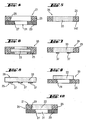
- FIG. 4 shows a partial cross-section through a composite shoe sole 21 with a lower sole 23 and a stabilizing device 25 located above before this shoe sole composite 21 is provided with a shoe stabilization material.
- the outsole 23 and the stabilizing device 25 each have passage openings 27 and 29, the total of an opening 31 form through the total thickness of the shoe sole composite 21.
- the opening 31 is thus formed by the sectional area of the two passage openings 27 and 29.
- shoe stabilization material 33 placed in the through hole 29 or arranged above this.
- FIG. 5 shows an example of a barrier unit 35 with a piece of shoe stabilization material 33, which is bordered by a stabilizer 25.
- the stabilizer is sprayed or sprayed around the length of shoe stabilizer material 33 such that the stabilizer material 25 penetrates and cures the fiber structure of the shoe stabilizer material 33 to form a strong bond.
- Thermoplastic polyurethane for example, which leads to a very good enclosure of the barrier material and bonds well with it, is suitable as the material for the encapsulation of the stabilization device or the injection molding onto the stabilization device.
- the shoe stabilization material 33 is adhered to the stabilizer 25.
- the stabilization device 25 preferably has a stabilizing frame 147 stabilizing at least the composite shoe sole 21.
- FIG. 6 shows a barrier unit 35, in which a piece of shoe stabilization material 33 is bordered by a stabilizer 25 in the sense that the edge region of the shoe stabilization material 33 is not only surrounded by the stabilizer 25, but also overlapped on both surfaces.
- FIG. 7 shows a barrier unit 35, in which a piece of stabilizing material 33 is enclosed by a stabilizer 25. At least one surface of the shoe stabilizing material 33 is provided with at least one stabilizing web 37 which at least partially traverses the surface of the opening. Preferably, the at least one stabilizing web 37 is arranged on a lower side, which is directed towards the outsole.
- FIG. 8 shows a barrier unit 35, in which a piece of shoe stabilization material 33 is provided with a stabilizing device 25 in the form of at least one stabilizing web 37.
- the stabilizing web 37 is arranged on at least one surface of the shoe-stabilizing material 33, preferably on the surface directed downwards towards the outsole 23.
- FIG. 9 1 shows a barrier unit 35 in which a piece of shoe stabilization material 33 is provided with a stabilizer 25 such that the shoe stabilizer material 33 is mounted on at least one surface of the stabilizer 25. In this case, the shoe stabilization material 33 covers the passage opening 29.
- FIG. 10 shows a composite shoe sole 21 according to FIG. 4 , the above the outsole 23 a barrier unit 35 according to FIG. 5 having.
- the bonding material during injection molding, encapsulation or gluing between stabilizing material 33 and stabilizer 25 not only adheres to the surfaces to be joined, but penetrates into the fiber structure and cures there.
- the fiber structure is additionally reinforced in their connection area.
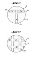
- FIGS. 11 and 12 Two embodiments of stabilizing web patterns 37 of stabilizing webs 37 applied to a surface of the shoe stabilizing material 33 are shown. While in the case of FIG. 11 on a circular surface 43 of the example underside of the shoe stabilizing material 33, which corresponds for example to an opening of the shoe sole composite 21, three individual webs 37a, 37b and 37c are arranged in a T-shaped mutual arrangement, for example by sticking to the underside of the shoe stabilization material 33, in the case of FIG. 12 a stabilization web 37 provided in the form of a stabilizing grid 37d.
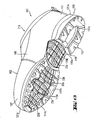
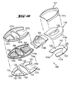
- FIG. 13 shows in perspective oblique view from below an embodiment of a shoe 101 according to the invention with a shaft 103 and a composite shoe sole 105.
- the shoe 101 has a forefoot portion 107, a midfoot portion 109, a heel portion 111 and a predominantlyeinschlüpfö réelle 113.
- the composite shoe sole 105 has on its underside a multi-part outsole 117, which has a outsole part 117a in the heel area, a outsole part 117b in the ball of the foot area and a outsole part 117c in the toe area of the composite shoe sole 105.
- outsole parts 117 are attached to the underside of a stabilizer 119 having a heel region 119a, a midfoot region 119b, and a forefoot region 119c.
- the composite shoe sole 105 will be explained in more detail with reference to the following figures.
- Further components of the composite shoe sole 105 may be damping sole parts 121 a and 121 b, which are applied in the heel region 111 and in the forefoot region 107 on the upper side of the stabilization device 119.
- the outsole 117 and the stabilizing device 119 each have passage openings which form openings through the composite shoe sole. These openings are covered by shoe stabilizing material parts 33a-33d in a water vapor permeable manner.
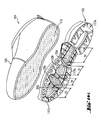
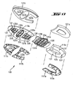
- Figure 14a shows the shoe 101 according to FIG. 13 in a manufacturing stage, in which the shaft 103 and the composite shoe sole 105 are still separated from each other.
- the shaft 103 is provided at its bottom-side lower end portion with a shaft bottom 115 having a waterproof, water vapor-permeable shaft bottom functional layer, which may be a waterproof, water vapor permeable membrane.
- the functional layer is preferably part of a multilayer functional layer laminate which, in addition to the functional layer, has at least one support layer, for example a textile side for processing protection.
- the shaft bottom 115 may be provided with a shaft mounting sole.
- the composite shoe sole has the already in FIG.
- openings 31 which are covered with shoe stabilization material parts 33a-33d.
- the webs 37 are shown within the peripheral edge of the respective openings. In further embodiments, three openings or two openings or an opening may be provided. In a another embodiment, more than four openings are provided.
- the composite shoe sole 105 may be attached to the sole-side shaft end either by injection molding or by gluing in order to obtain the state according to FIG FIG. 13 manufacture. For a detailed explanation of the functional layer and its laminate, and the connection with the mounting sole is on the description and the FIGS. 22 to 27 directed.
- FIG. 14b shows the same shoe structure as in Figure 14a , with the difference that the shoe is in Figure 14a has four openings 31, while the shoe after FIG. 14b equipped with two openings 31.
- the webs 37 are arranged within the peripheral edge of the respective aperture 31 and form no limitation of the aperture 31. The area of an opening is determined less the total area of the webs crossing it, since this land area blocks the transport of water vapor.
- FIG. 14c also shows the same shoe structure as in Figure 14a wherein the four apertures 31 in this embodiment are free of stabilizing webs 37.
- the openings 31 as well as in Fig. 14a and 14b be closed with one or more pieces of stabilizing material 33.
- FIG. 15 shows a composite shoe sole 105 with a top remote from the outsole 117 top.
- the stabilizer 119 is covered in its central portion 119b and in its forefoot portion 119c with a plurality of pieces 33a, 33b, 33c and 33d of a shoe-stabilizing material 33, with which FIG. 15 not visible openings of the shoe sole composite 105 are covered.
- a damping sole part 121a and 121b are respectively applied on the upper side of the stabilizing device 119, in the heel area substantially over the entire area and in the forefoot area with recesses where the shoe stabilizing material parts 33b, 33c and 33d are located.
- the outsole parts of the outsole 117, the stabilizer 119 and the damping sole parts 121 a and 121 b have different functions within the composite shoe sole, they are expediently constructed with different materials.
- the outsole parts which are to have a good abrasion resistance, for example, consist of an outsole material suitable thermoplastic polyurethane (TPU) or rubber.
- the damping sole parts 121 a and 121 b which are to cause a shock absorption in the walking movements for the user of the shoe, consist of correspondingly elastically yielding material, such as ethylene-vinyl acetate (EVA) or polyurethane (PU).
- the stabilization device 119 which serves as a support for the non-contiguous outsole parts 117a, 117b, 117c and for the likewise non-coherent damping sole parts 121a, 121b as a holder and for the entire shoe sole dressing 105 and should have a corresponding elastic stiffness, consists for example of at least a thermoplastic.
- suitable thermoplastics are polyethylene, polyamide, polyamide (PA), polyester (PET), polyethylene (PE), polypropylene (PP) and polyvinyl chloride (PVC).
- Other suitable materials are rubber, thermoplastic rubber (TR, from Thermoplastic Rubber) and polyurethane (PU). Also suitable is thermoplastic polyurethane (TPU).
- FIG. 15 Shoe sole composite shown is in FIG. 16 shown in exploded view, ie in a representation in which the individual parts of the shoe sole composite 105 are shown separately from each other, with the exception of the Schuhstabilmaschinesmaterialmaschine 33a, 33b, 33c and 33d, which are shown as already arranged on the Stabilmaschiness noticeds kind 119b and 119c.
- the stabilizing device 119 has its parts 119a, 119b and 119c as initially separate parts, which are connected to one another in the course of assembly of the shoe sole composite 105 to the stabilizing device 119, which can be done by welding or gluing the three stabilizer parts together.
- FIG. 16 shown in exploded view, ie in a representation in which the individual parts of the shoe sole composite 105 are shown separately from each other, with the exception of the Schuhstabilmaschinesmaterialmaschine 33a, 33b, 33c and 33d, which are shown as already arranged on the Stabilmaschiness noticed 119b and 119c.
- a passage opening 125 in the heel part 119 a of the stabilization device 119 is not closed with shoe stabilization material 33 but with the full-surface damping sole part 121 a. This achieves a better damping effect of the composite shoe sole 105 in the heel region of the shoe, where perspiration moisture removal may under certain circumstances be less necessary since foot perspiration forms predominantly in the forefoot and midfoot region, but not in the heel region.
- the cushioning sole portion 121b is provided with through holes 127a, 127b and 127c dimensioned so that the shoe stabilizing material portions 33b, 33c, 33d surrounding boundary edges 129a, 129b and 129c of the stabilizer portion 119c can be received in the through holes 127a, 127b and 127c, respectively.
- the parts of the stabilizer 119a, 119b and 119c have a planar surface without a delimiting edge 129a, 129b, 129c, so that the stabilizing material 33 is placed flush with the surface of the stabilizer in its openings.
- the sole composite is formed only by the barrier unit constructed of shoe stabilizing material 33 and the stabilizer 119, and the outsole.
- FIG. 16 shoe sole composite parts 105 shown obliquely above are shown in FIG. 17 also shown in a separate arrangement, but in an oblique view from below.
- the outsole parts 117a to 117c are provided in the usual way with an outsole profile in order to reduce the risk of slipping.
- the undersides of the stabilizer means 119a and 119c have on their underside a plurality of knob-like projections 131 which are adapted to receive in FIG. 16 to see complementary recesses 133 in the tops of the outsole parts 117a, 117b and 117c for positionally correct connection of the outsole parts 117a to 117c with the associated Stabilmaschines Rheins kind 119a and 119c serve.
- openings 135a, 135b, 135c and 135d can be seen in the stabilizer means 119b and 119c which are covered with the respective shoe stabilization material part 33a, 33b, 33c and 33d in a water vapor permeable manner, whereby the openings 31 (FIG. FIG. 4 ) of the composite shoe sole 105 are closed in a way permeable to water vapor.
- the shoe stabilization material parts are arranged with their smooth surface facing the outsole.
- the openings 135a to 135d are each bridged with a stabilizing grid 137a, 137b, 137c and 137d, which each form a stabilizing structure in the region of the respectively associated opening of the stabilizing device 119.
- these stabilizing gratings 137a-137d act against the penetration of larger foreign objects up to the shoe stabilizing material 33 or beyond, which could be unpleasantly felt by the user of the shoe.
- the barrier unit is additionally designed as an outsole with an outsole profile.
- connecting elements 139 provided at the axial ends of the stabilizer device part 119b on the middle side which, when the stabilizer 119 is assembled from the three stabilizer parts 119a to 119c, overlap on the upper sides of the stabilizer parts 119a and 119c facing away from the outsole side to be, for example, by Verschwei- hybrid or bonding.
- FIG. 18 shows in opposite FIG. 17 enlarged representation of the two stabilizing device parts 119c and 119b before their attachment to each other, the openings 135b to 135d of the forefoot stabilization device part 119c and the stabilizing grid structures therein are particularly well visible.
- the middle stabilization device part 119b shows bent-up frame and lattice parts on the longitudinal sides.
- the shoe stabilizing material piece 33a to be placed on the stabilizing device part 119b is provided on its longitudinal sides with correspondingly curved side wings 141.
- FIG. 19 shows another embodiment of the forefoot portion 107 and the midfoot portion 109 according to FIG. 17 ,
- the stabilizer 119 is formed without stabilizing webs 37.
- the surface of the stabilizing material 33 terminates flush with the surface of the stabilizing device 119.
- the openings 135 ad are each provided with circumferential support projections 150 for receiving the stabilizing material 33, so that it can be fitted into the openings 135 ad.
- the at least one opening 135 a-135d of the stabilizer 119b and 119c is bounded by the frame 147 of the stabilizer 119 and not by possibly present webs 37 in the openings 135a-135d.
- limiting edges 129 a-129c represent in this embodiment, a part of the respective frame 147.
- FIGS. 20 and 21 Another modification of the barrier foot portion provided with the stabilizer portion 119b and the shoe stabilizing material portion 33a is provided in FIGS FIGS. 20 and 21 shown in FIG. 20 in the assembled state and in FIG. 21 while these two parts are still separated.
- the stabilization device part 119b provided for the midfoot area is provided only in the central area with an opening and a stabilizing grid 137a therein, while the two wing parts 143 are continuous on the longitudinal sides of the stabilizing device part 119b, ie they have no opening but only on their underside with stabilizing ribs 145 are provided.
- the shoe stabilizing material piece 33a provided for this barrier unit part is narrower than in the variants of FIGS Figures 18 and 19 because it is not the side wings 141 according to the Figures 18 and 19 needed.
- FIGS 22 to 29 is constructed with a composite shoe sole according to the invention.
- the show Figures 22 . 24 and 25 an embodiment of the footwear according to the invention, in which the shaft bottom 221 has a shaft mounting base 233 and additionally a functional layer laminate 237, while the Figures 26 and 27 show an embodiment of footwear according to the invention, in which a Schaftêtfunktions slaughterlamintechnik 237 simultaneously the function of a shaft mounting base 233 takes over.
- the FIG. 28 shows a further embodiment of the shoe sole composite 105th
- the shoe 101 in accordance with the Figures 13 and 14 a - c has a shank 103, which has an outer material layer 211 on the outside, an inner lining layer 213 and a waterproof, water vapor permeable, shank functional layer layer 215 located therebetween, for example in the form of a membrane.
- the shank functional layer layer 215 may be in composite with the lining layer 213 as a 2-ply laminate or as a 3-ply laminate with the sheath-functional layer layer 215 embedded between the lining ply 213 and a textile downside 214.
- the upper shank end 217 is depending on whether the cutting plane in the Figures 22 and 26 illustrated cross-sectional view in the forefoot or midfoot area, closed or additionallyeinschlüpfö réelle 113 (Figure 13) open.
- the shaft 103 is provided with a shaft bottom 221, with which the sole-side lower end of the shaft 103 is closed.
- the shaft bottom 221 has a shaft mounting sole 233 which is connected to the sole side shaft end portion 219, which in the embodiments according to FIGS FIGS. 22 to 27 done by means of a Strobelnaht 235.
- a shaft bottom functional layer laminate 237 disposed below the shaft mounting sole 233 and extending beyond the circumference of the shaft mounting sole 233 to the sole side shaft end region 219.
- the shaft bottom functional layer laminate 237 may be a 3-layer laminate, with the shaft bottom functional layer 247 is embedded between a textile side and a further textile layer. It is also possible to provide the Schaftêtfuntions Mrs 247 only with the textile side.
- the upper material layer 211 is shorter than the shank functional layer layer 215, so that there is provided a projection of the shank functional layer layer 215 opposite the upper material layer 211 and the outer surface of the shank functional layer layer 215 is exposed there.
- a mesh 241 or other material permeable to sealing material is arranged between the sole side end 238 of the upper material layer 211 and the sole end 239 of the shaft functional layer layer 215.
- the mesh band 241 is preferably made of a monofilament material so that it has no water conductivity.
- the mesh band is preferably used for injection-molded soles. If the sole composite is attached to the shaft by means of adhesive, instead of the mesh belt, the sole-side end 238 of the upper material layer 211 can be fastened by means of adhesive 249 to the Zwickschaftfunktions slaughterlaminat ( FIG. 24 ).
- a sealing material 248 is arranged between the shaft bottom functional layer laminate 237 and the sole end 239 of the shaft functional layer layer 215, by means of which a watertight connection between the sole end 239 of the shaft functional layer layer 215 and the peripheral portion 245 of the shaft bottom functional layer laminate 237 is made, this seal acts through the net 241 therethrough.
- net band solution serves to prevent water that runs down or creeps on the Obermateriallage 211, reaches the Strobelnaht 235 and penetrates from there into the shoe interior. This is prevented by the fact that the sole-side end 238 of the upper material layer 211 terminates at a distance from the sole-side end 239 of the shaft functional layer layer 215, which is bridged with the non-water-conducting net 241, and in the region of the supernatant of the Schaftfunktions harshlage 215, the sealing material 248 is provided.
- the network tape solution is known per se from the document EP 0298360 B1 ,
- connection technologies used in the shoe industry can be used for preferably watertight connection of the shaft to the shaft bottom.
- the illustrated mesh tape solution in the Figures 22 . 25-27 and the nipped solution in FIG. 24 are exemplary embodiments.
- FIG. 26 shown shaft construction is consistent with the in FIG. 22 shown shaft construction, with the exception that there is no separate shaft mounting base 233 is provided, but that the Schaftêtfunktions Anlagenlaminat 237 simultaneously assumes the function of a shaft mounting base 233 with. Accordingly, the circumference of the shaft bottom functional layer laminate 237 is that in FIG FIG. 26 in the region of this strobe seam 235 so that the transition between the sole-side end 239 of the shank functional layer layer 215 and the peripheral region of the shank bottom functional layer laminate 237 is completely sealed, including the strobe seam 235.
- the sectional view of the shoe sole composite 105 shows the stabilizer device part 119c with its opening 135c, a bridge of the associated stabilizing grid 137c bridging this opening, the upwardly upstanding boundary edge 129b, the shoe stabilizing material piece 33c inserted in this limiting edge 129b, the damping sole part 121b on the upper side the stabilizer portion 119c and the outsole portion 117b on the underside of the stabilizer portion 119c.
- both embodiments of the agree Figures 22 and 26 match.
- FIG. 23 shows an example of a barrier unit 35, in which a piece of shoe stabilization material 33 is provided on its underside with at least one stabilizing web 37.
- an adhesive 39 is applied, via which the shoe stabilizing material 33 is connected to the waterproof, water vapor permeable shaft bottom 221, which is located outside of the composite shoe sole above the barrier unit 35.
- the adhesive 39 is applied in such a way that the shaft bottom 221 remains unconnected to the shoe stabilizing material 33 wherever it abuts the underside of the shoe stabilizing material 33 no material of the stabilizing web 37 is located. In this way, it is ensured that the water vapor permeability function of the shaft bottom 115 is disturbed by adhesive 39 only where the shoe stabilizing material 33 can not allow any water vapor transport anyway due to the arrangement of the stabilizing web 37.
- the shaft bottom functional layer 247 of the shaft bottom functional layer laminate 237 in all embodiments is preferably a microporous functional layer, for example of stretched polytetrafluoroethylene (ePTFE).
- ePTFE stretched polytetrafluoroethylene
- FIG. 24 shows an embodiment in which the composite sole 105 according to the invention is attached by means of fastening adhesive 250 on the shaft bottom 221.
- the sheath functional layer laminate 216 is a three-layer composite having a fabric layer 214, a shank functional layer 215, and a liner 213.
- the sole-side end 238 of the topsheet 211 is attached to the sheath-functional layer laminate 216 with pinch adhesive 249.
- the fastening adhesive 250 is applied flat on the surface of the composite sole with the exception of the perforations 135c and the shoe stabilizing material 33c arranged in the region of the perforations 135c.
- the attachment adhesive 250 penetrates up to and partially into the shaft functional layer laminate 216 and at and partially into edge regions of the shaft bottom functional layer laminate 237.
- FIG. 25 is an illustration of the shaft structure according to FIG. 22 with a molded soles composite.
- the three-ply shaft bottom functional layer laminate 237 is attached to the shaft mounting base 233 such that the textile side 246 points to the composite sole. This is advantageous because the sole spray 260 may more readily penetrate and anchor into the thin textile backing, thus providing a strong bond to the shaft bottom functional layer 237.
- the barrier unit with the at least one opening 135c and the at least one piece of shoe stabilization material 33c is present as a prefabricated unit and is inserted into the injection mold before the injection process.
- the sole injection material 260 is correspondingly injection molded onto the shaft bottom, penetrating through the net 241 to the shaft functional layer laminate 216.
- FIG. 27 shows an enlarged and fragmentary view of FIG. 26
- the sole compound 105 shows a further embodiment of the barrier unit 35 according to the invention.
- the shoe stabilizer 119c forms part of the sole composite 105 and does not extend to the outer periphery of the sole composite 105.
- a piece of shoe stabilizing material 33c is attached so that the material 33c rests on the peripheral continuous plan shaped boundary edge 129 of the opening 135c.
- the sole composite 105 can be fastened with attachment adhesive 250 on the shaft bottom 221 or sprayed with sole injection material 260.
- FIG. 27 also clearly shows that in the embodiment in which the shaft bottom functional layer laminate 237 takes over the function of the shaft mounting sole, laminate immediately above the opposite top of the shoe stabilization material piece 33c comes to rest, which is particularly advantageous.
- the shaft bottom functional layer laminate 237 and the shoe stabilizing material piece 33c there can not form an air cushion which might impair the water vapor removal, and the shoe stabilizing material piece 33c and especially the shaft bottom functional layer 247 are particularly close to the foot sole of the user of such shoe, facilitating water vapor removal which is co-determined by the existing temperature gradient between shoe interior and shoe exterior.
- the composite shoe sole 105 and the shaft 103 are provided, wherein the sole-side lower region of the shaft can still be open.
- the shank 103 is provided at its sole-side shank end portion 219 with a shank bottom 221 formed by either the shank-bottom-function-layer laminate 237 or such shank-bottom-function-layer laminate 237 and a separate shaft-mounting sole 233.
- a shaft provided with a shaft bottom functional layer laminate 237 from the beginning in the sole side shaft end portion 219 may be provided.
- the composite shoe sole 105 is attached to the sole side shaft end 219, which can be done either by gluing the shoe sole composite 105 with the lower shaft end by means of an adhesive 250 or by a shoe sole composite 105 is molded onto the underside of the shaft.
- the connection between the lower shaft end and composite shoe sole 105 occurs such that the shaft bottom functional layer 239 remains unconnected to the shoe stabilizing material 33c of the shaft bottom composite 221 at least in the region of the openings of the composite shoe sole 105.
- FIG. 28 is an illustration of another embodiment of the composite sole according to the invention.
- the perspective view shows a plurality of openings 135 in the shoe stabilizer 119, which are arranged from the toe area to the heel area of the composite sole.
- the stabilizing material 33 is also present in the heel area.
- FIG. 29 is a representation of another embodiment of the composite sole according to the invention in cross-sectional view.
- the sole composite 105 of this embodiment is the in FIG. 26 Similar to the soles shown.
- the sole composite 105 according to FIG. 29 has an outsole, wherein in this figure a cross section through the ball of the foot region of the composite sole 105 is shown and therefore a cross section through the corresponding outsole part 117b.
- the teaching according to FIG. 29 But also applies to the other areas of the composite sole 105, so also for the foot middle part and the heel part.
- the outsole part 117b has a tread 153, which committed while running the Ground touched.
- the stabilizing device part 119c with its opening 135c, its upwardly upstanding boundary edge 129b, the shoe stabilizing material piece 33c inserted into the limiting edge 129b, the damping sole part 121b on the upper side of the stabilizer part 119c and the sole part 117b on the lower side of the stabilizer part 119c.
- a supporting member 151 is attached at the bottom of the shoe stabilizing material piece 33c. This extends from the tread-facing side of the shoe-stabilizing material 33 to the level of the tread 153, such that the shoe-stabilizing material 33 is supported when running on the support member 151 on the ground committed. That means that an in FIG.
- a plurality of support members 151 may be arranged to increase the support action for the shoe stabilizing material piece 33c and to make more uniform over the surface extension thereof.
- the support function can also be obtained by using the in FIG. 26 stabilizing web 137c shown at the same time forms as a support member 151 by the stabilizer bar 137c can not end at a distance from the underside of the outsole part 117b serving as a running surface but extended to the level of this underside.
- the stabilizing land 137c is given the dual function of stabilizing and supporting the shoe stabilizing material piece 33c.
- the in FIG. 11 stabilizing webs 37c or the stabilizing grid 37d shown in FIG. 12 are formed entirely or partially as supporting elements 151.
- a high water vapor permeability value is achieved because large openings are provided in the composite shoe sole 105 and these are closed with material of high water vapor permeability and because also at least in the area of the openings no water vapor exchange obstructing connection between the water vapor permeable shoe stabilizing material 33 and the shank bottom functional layer is and such a compound is present at most in the areas outside the apertures of the shoe sole composite 105, which are not actively involved in water vapor exchange, such as the edge regions of the shoe sole composite 105.
- the shaft bottom functional layer is arranged close to the foot in the structure according to the invention, which leads to accelerated water vapor removal.
- Shaft bottom functional layer laminate 237 may be a multilayer laminate having two, three, or more layers. Contained is at least one functional layer with at least one textile support for the functional layer, wherein the functional layer can be formed by a waterproof, water vapor permeable membrane 247, which is preferably microporous.
- the thickness of the shoe stabilization material according to the invention is tested according to DIN ISO 5084 (10/1996).
- the puncture resistance of a fabric can be measured with a measuring method used by the EMPA (Swiss Federal Laboratories for Materials Testing and Research) using a testing machine of the Instron tensile testing machine (model 4465).
- EMPA Error tensile testing machine
- a punching iron By means of a punching iron, a round textile piece with a diameter of 13 cm is punched out and fastened on a support plate in which there are 17 holes.
- the force for piercing the textile piece is measured by means of a load cell (a force transducer). The result is determined from a sample number of three samples.
- a functional layer is considered to be "waterproof", if appropriate including seams provided on the functional layer, if it ensures a water inlet pressure of at least 1x10 4 Pa.
- the functional layer material ensures a water inlet pressure of over 1x10 5 Pa.
- the water inlet pressure shall be measured by a test method in which distilled water is applied at 20 ⁇ 2 ° C to a sample of 100 cm 2 of the functional layer with increasing pressure. The pressure increase of the water is 60 ⁇ 3 cm Ws per minute. The water inlet pressure then corresponds to the pressure at which water first appears on the other side of the sample. Details of the procedure are specified in the ISO standard 0811 from the year 1981.
- Whether a shoe is waterproof for example, with a centrifuge assembly in the US-A-5,329,807 be tested type tested.
- the water vapor permeability values shoe stabilization material according to the invention are tested using the so-called cup method according to DIN EN ISO 15496 (09/2004).
- a functional layer As a "water vapor permeable" a functional layer is considered, if it has a water vapor transmission rate Ret of less than 150 m2 ⁇ Pa ⁇ W -1 .
- the water vapor permeability is tested according to the Hohenstein skin model. This test method is described in DIN EN 31092 (02/94) or ISO 11092 (1993).
- the shoe bottom structure has a Moisture Vapor Transmission Rate (MVTR) in the range of 0.4 g / h to 3 g / h , which may range from 0.8 g / h to 1.5 g / h, and in one practical embodiment is 1 g / h.
- MVTR Moisture Vapor Transmission Rate
- the degree of water vapor permeability of the shoe bottom structure can be compared with that in the document EP 0396716 B1 determined measurement method, which has been designed to measure the water vapor permeability of an entire shoe.
- the measuring method according to EP 0 396 716 B1 also be used by with the in Fig. 1 of the EP 0 396 716 B1 the measurement setup shown is measured in two consecutive measurement scenarios, namely once the shoe with a water vapor permeable shoe bottom construction and another time the otherwise identical shoe with a water vapor-resistant shoe bottom construction. From the difference between the two measured values then the proportion of water vapor permeability can be determined, which goes back to the water vapor permeability of the water vapor permeable shoe bottom structure.
- abrasion resistance for the abrasion measurements for obtaining the abrasion values in the comparative table
- two measuring methods have been used.
- testing was carried out with a Martindale abrasion tester (in the table "Abrasion Carbon") in which according to the standard DIN EN ISO 124947-1; -2; (04/1999) scrubbed the sample to be tested against sandpaper.
- grit 180 plus standard foam was clamped in the sample holder.
- standard felt plus the test specimen were clamped in the sample table.
- the sample was inspected every 700 tours and the sandpaper replaced.
- Lissajous figures represent a periodically repeating overall picture with a suitable choice of the ratio of the frequencies involved, which is composed of relatively individual figures.
- the passage through one of these individual figures is referred to as a tour in the context of the abrasion test.
- a tour in the context of the abrasion test.
- the comparison table there are two tour values for each of the materials, which were created from two abrasion tests each with the same material.
- the hardness according to Shore is the resistance to the penetration of a certain shape of a body under a defined spring force.
- the Shore hardness is the difference between the numerical value 100 and the indentation depth of the indenter divided by the scale value 0.025 mm in mm under the effect of the test load.
- a truncated cone with an opening angle of 35 ° is used as the indenter, and in Shore D a cone with an opening angle of 30 ° and a tip radius of 0.1 mm.
- the indenters are made of polished, hardened steel.
- materials with a Shore A hardness> 80 should be suitably tested to Shore D and materials with a Shore D hardness ⁇ 30 to Shore A.
- Material which is associated with the shoe (s) / materials present in the shoe such as the upper, sole, membrane, mechanical protection and resistance to deformation, as well as the penetration of external objects / foreign bodies / objects e.g. through the sole allows, while maintaining a high water vapor transport, i. a high climate comfort in the shoe.
- the mechanical protection and resistance to deformation is mainly due to the low elongation of the shoe stabilizer material.
- the fiber composite must have at least two fiber components. These components may be fibers (eg, staple fibers), filaments, fiber elements, yarns, strands, and the like. act. Each fiber component is either made of one material or contains at least two different proportions of material, one of which softens / melts at a lower temperature than the other fiber portion (Bico). Such bico-fibers may have a core-shell structure - here a core fiber portion is sheathed with a sheath fiber portion - having a side-by-side structure or an islands-in-the-sea structure. Such processes and machines are available from Rieter Ingolstadt, Germany and / or Schalfhorst in Mönchengladbach, Germany. The fibers can be simply spun, multifilament, or multiple ruptured fibers with intertwined frayed ends. The fiber components can be distributed uniformly or unevenly in the fiber composite.
- the entire fiber composite must preferably be temperature stable at least 180 ° C.
- a uniform and smooth surface on at least one side of the fiber composite is achieved by means of pressure and temperature. This smooth surface shows "down" to the ground / floor, thus ensuring that the smooth surface particles / foreign bodies bounce off better or are easily rejected.
- the properties of the surface or of the overall structure of the fiber composite or stabilizing material depend on the fibers selected, the temperature, the pressure and the time over which the fiber composite was subjected to temperature and pressure.
- the fibers are deposited on a conveyor belt and confused.
- Sheets made with warp and weft threads made with warp and weft threads.
- the melting temperature is the temperature at which the fiber component or portion becomes liquid. In the field of polymer or fiber structures, the melting temperature is understood to be a narrow temperature range in which the crystalline regions of the polymer or fiber structure melt and the polymer changes to the liquid state. It is above the softening temperature range and is an essential parameter for semicrystalline polymers. Melted is the change in the state of aggregation of the fiber or parts of the fiber at a characteristic temperature of too viscous / flowable.
- the second fiber component or the second fiber portion must only be soft / plastic, but not liquid. That the softening temperature used is below the melting temperature at which the component / fraction dissolves.
- the fiber component or parts thereof are softened such that the more temperature-stable component is embedded in the softened parts.
- the first softening temperature range of the first fiber component is higher than the second softening temperature range of the second fiber component or the second fiber portion of the second fiber component.
- the lower limit of the first softening range may be below the upper limit of the second softening range.
- the adhesive softening temperature can also be chosen so that a softening of the fibers of the second fiber component takes place to such an extent that an adhesion not only of fibers of the second fiber component with each other but also a partial or total sheathing of individual points of the fibers of the first fiber composite with softened material
- the fibers of the second fiber composite arises, so a partial or total embedding such locations of fibers of the first fiber composite in the material of fibers of the second fiber component, that a correspondingly increased stabilization solidification of the fiber composite arises.
- the shoe stabilizer material must be temperature stable for injection molding. The same applies to injection molding (about 170 ° C - 180 ° C) or vulcanization of the shoe sole. If the stabilizing device is to be injection-molded, the shoe stabilizing material must have a structure such that the stabilizing device can at least penetrate into the structure of the shoe-stabilizing material or, if appropriate, penetrate it.
- the shaft bottom functional layer and optionally the shaft functional layer may be formed by a waterproof, water vapor permeable coating or by a waterproof, water vapor permeable membrane, which may be either a microporous membrane or a nonporous membrane.
- the membrane comprises stretched polytetrafluoroethylene (ePTFE).
- Suitable materials for the waterproof, water-vapor-permeable functional layer are in particular polyurethane, polypropylene and polyester, including polyether esters and their laminates, as described in the publications US-A-4,725,418 and US-A-4,493,870 are described.
- stretched microporous polytetrafluoroethylene ePTFE
- ePTFE stretched microporous polytetrafluoroethylene
- a microporous functional layer is understood to be a functional layer whose average pore size is between about 0.2 ⁇ m and about 0.3 ⁇ m. The pore size can be measured with the Coulter Porometer (trade name) manufactured by Coulter Electronics, Inc., Hialeath, Florida, USA.
- the barrier unit is formed by the shoe stabilization material and optionally by the stabilization device in the form of at least one web and / or a frame.
- the barrier unit may be in the form of a prefabricated component.
- the composite shoe sole consists of shoe stabilizing material and at least one stabilizing device and / or at least one outsole and possibly further sole layers, the shoe stabilizing material closing the at least one opening extending through the composite shoe sole thickness.
- An opening is the area of the composite shoe sole through which water vapor transport is possible.
- the outsole and the stabilizing device each have passage openings, which together form an opening through the total thickness of the composite shoe sole.
- the opening is thus formed by the sectional area of the two passage openings. Possibly existing webs are arranged within the peripheral edge of the respective opening and form no limitation of the opening.
- the area of an opening is determined less the area of all webs crossing it, since this land area blocks the transport of water vapor and thus does not constitute a breakthrough area.
- the stabilizer acts as additional stabilization of the shoe stabilizer material, is shaped and attached to the shoe stabilizer material such that the water vapor transmission rate of the shoe stabilizer material is only marginally affected, if at all. This is achieved by covering only a small area of the shoe-stabilizing material with the stabilizing device.
- the stabilizer is directed down to the ground.
- the stabilization device is not a protective function but a stabilization device.
- the at least one opening of the stabilization device is limited by its at least one frame.
- the area of an opening is determined less the area of all webs crossing it.
- Footwear consisting of a composite shoe sole and a closed top (shaft).
- the shoe bottom covers all layers below the foot.
- the thermal activation takes place by applying energy to the fiber composite, which leads to an increase in the temperature of the material up to the softening temperature range.
- Tested is a composite shoe sole according to centrifuge arrangement in the US-A-5,329,807 Before testing it must be ensured that a possibly existing shaft bottom functional layer is made permeable to water. From a water-permeable composite shoe sole one goes off if this test is failed. Optionally, the colored liquid test is performed to identify the path of the fluid through the composite shoe sole.
- Laminate is a composite consisting of a waterproof, water vapor permeable functional layer with at least one textile layer.
- the at least one textile layer also called the side, serves mainly to protect the functional layer during its processing.
- This is called a 2-layer laminate.
- a 3-layer laminate consists of a waterproof, water-vapor-permeable functional layer, which is embedded between two textile layers, wherein a point-like adhesive can be applied between these layers.
- a functional layer is considered to be "waterproof”, if appropriate including seams provided on the functional layer, if it ensures a water inlet pressure of at least 1x10 4 Pa.
- Outsole means the part of the composite shoe sole that touches the ground / subfloor or makes the main contact with the ground / subfloor:
Landscapes
- Engineering & Computer Science (AREA)
- Textile Engineering (AREA)
- Mechanical Engineering (AREA)
- Health & Medical Sciences (AREA)
- Epidemiology (AREA)
- General Health & Medical Sciences (AREA)
- Public Health (AREA)
- Chemical & Material Sciences (AREA)
- Materials Engineering (AREA)
- Footwear And Its Accessory, Manufacturing Method And Apparatuses (AREA)
Description
Die Erfindung betrifft Schuhstabilisierungsmaterial zum Einsatz in Schuhwerk, eine mit solchem Schuhstabilisierungsmaterial aufgebaute Barriereeinheit, einen mit solchem Schuhstabilisierungsmaterial oder der Barriereeinheit aufgebauten Schuhsohlenverbund, mit einem solchen Schuhsohlenverbund aufgebautes Schuhwerk und ein Verfahren zur Herstellung von solchem Schuhwerk.This invention relates to shoe stabilizing material for use in footwear, to a barrier unit constructed with such shoe stabilizing material, to a shoe sole composite constructed with such shoe stabilizing material or barrier unit, to footwear constructed with such composite shoe sole, and to a method of making such footwear.
Die Notwendigkeit, sich alternativ entweder für einen wasserdichten, jedoch Schwitzfeuchtigkeit stauenden oder für einen für Schwitzfeuchtigkeit durchlässigen jedoch auch wasserdurchlässigen Schuhbodenaufbau entscheiden zu müssen, besteht nicht mehr, seit es Schuhbodenaufbauten gibt, die trotz Wasserdampfdurchlässigkeit wasserdicht sind, und zwar aufgrund der Verwendung einer perforierten oder mit Durchbrechungen versehenen Laufsohle und einer darüber angeordneten wasserdichten, wasserdampfdurchlässigen Funktionsschicht, beispielsweise in Form einer Membran. Beispiele zeigen die Dokumente
Da der menschliche Fuß eine starke Schwitzneigung hat, geht das Bestreben der vorliegenden Erfindung dahin, Schuhwerk verfügbar zu machen, das einen Schuhbodenaufbau mit einer besonders hohen Wasserdampfdurchlässigkeit aufweist, ohne dessen Stabilität zu stark zu beeinträchtigen.Since the human foot has a strong sweating tendency, the aim of the present invention is to make available footwear having a shoe bottom construction with a particularly high water vapor permeability, without unduly impairing its stability.
Bei Schuhwerk mit einer Laufsohle mit klein bemessenen Durchbrechungen gemäß
Sohlenaufbauten gemäß
Ähnlich verhält es sich bei Sohlenaufbauten gemäß
Eine bessere Stabilisierung des Schuhbodenaufbaus ist bei einem Sportschuh gemäß
Andere Lösungen, beispielsweise gemäß
Bei Ausführungsformen der
Bei einer anderen Ausführungsform der
Aus
Aus
Aus
Es ist heutzutage bei der Herstellung von Schuhwerk gängige Arbeitsteilung, dass ein Hersteller den Schuhschaft herstellt und ein anderer Hersteller für die Herstellung der zugehörigen Schuhsohle oder des zugehörigen Schuhsohlenverbundes oder für deren Anspritzen an den Schuhschaft zuständig ist. Da die Hersteller für Schuhsohlen üblicherweise weniger für den Umgang mit wasserdichten, wasserdampfdurchlässigen Membranen ausgerüstet und erfahren sind, sind Schuhbodenkonzepte erstrebenswert, bei welchen der Schuhsohlenverbund als solcher frei von einer Membran ist und die Membran einen Teil des Schaftbodens bildet, an dem der Schuhsohlenverbund angeordnet wird.It is nowadays in the production of footwear common division of labor that one manufacturer manufactures the shoe upper and another manufacturer is responsible for the production of the associated shoe sole or the associated shoe sole composite or for their injection molding on the shoe upper. Since shoe sole manufacturers are usually less equipped and experienced in dealing with watertight, water-vapor-permeable membranes, shoe floor concepts are desirable in which the shoe sole composite as such is free of a membrane and the membrane forms part of the shaft bottom on which the composite shoe sole is placed ,
Es ist daher eine Aufgabe der vorliegenden Erfindung, für Schuhwerk, das einen Schuhbodenaufbau mit dauerhafter Wasserdichtigkeit und mit einer besonders hohen Wasserdampfdurchlässigkeit unter Erlangung einer möglichst hohen Stabilität des Schuhbodenaufbaus aufweist, geeignete Schuhbodenkomponenten sowie damit aufgebautes Schuhwerk verfügbar zu machen.It is therefore an object of the present invention, for footwear, which has a shoe bottom structure with permanent waterproofness and with a particularly high water vapor permeability while achieving the highest possible stability of the shoe bottom structure, suitable shoe floor components as well as built-up footwear available.
Zur Lösung dieser Aufgabe macht die Erfindung verfügbar eine wasserdampfdurchlässige Barriereneinheit gemäß Anspruch 1, einen wasserdampfdurchlässigen Schuhsohlenverbund gemäß Anspruch 9, ein Schuhwerk gemäß Anspruch 12 und ein Verfahren zur Herstellung von Schuhwerk gemäß Anspruch 14. Weiterbildungen dieser Gegenstände und Verfahren sind in den je zugehörigen abhängigen Ansprüchen angegeben.To achieve this object, the invention provides a water vapor permeable barrier unit according to
Gemäß einem ersten Aspekt der Erfindung wird für die erfindungsgemäße Barriereneinheit ein Schuhstabilisierungsmaterial verfügbar gemacht, aufweisend einen Faserverbund mit einer ersten Faserkomponente und einer zwei Faseranteile aufweisenden zweiten Faserkomponente, wobei die erste Faserkomponente eine erste Schmelztemperatur und einen darunter liegenden ersten Erweichungstemperaturbereich aufweist und ein zweiter Faseranteil der zweiten Faserkomponente eine zweite Schmelztemperatur und einen darunter liegenden zweiten Erweichungstemperaturbereich aufweist, die erste Schmelztemperatur und der erste Erweichungstemperaturbereich höher sind als die zweite Schmelztemperatur und der zweite Erweichungstemperaturbereich, der erste Faseranteil der zweiten Faserkomponente eine höhere Schmelztemperatur und eine höhere darunter liegende Erweichungstemperatur als der zweite Faseranteil aufweist, und der Faserverbund infolge thermischer Aktivierung des zweiten Faseranteils der zweiten Faserkomponente mit einer im zweiten Erweichungstemperaturbereich liegenden Klebeerweichungstemperatur thermisch verfestigt ist unter Aufrechterhaltung von Wasserdampfdurchlässigkeit im thermisch verfestigten Bereich.According to a first aspect of the invention, a shoe stabilizer material is provided for the barrier unit of the invention comprising a fiber composite having a first fiber component and a second fiber component having two fiber portions, the first fiber component having a first melting temperature and a first softening temperature range thereunder and a second fiber portion of the first fiber component second fiber component has a second melting temperature and an underlying second softening temperature range, the first melting temperature and the first softening temperature range are higher than the second melting temperature and the second softening temperature range, the first fiber content of the second fiber component has a higher melting temperature and a higher underlying softening temperature than the second Has fiber content, and the fiber composite due to thermal activation of the second fiber portion of the second fiber component is thermally bonded with a lying in the second softening temperature range adhesive softening temperature while maintaining water vapor permeability in the thermally bonded area.
Unter der Schmelztemperatur versteht man auf dem Gebiet der Polymer- bzw. Faserstrukturen einen schmalen Temperaturbereich, in dem die kristallinen Bereiche der Polymer- bzw. Faserstruktur aufschmelzen und das Polymer in den flüssigen Zustand übergeht. Er liegt über dem Erweichungstemperaturbereich und ist eine wesentliche Kenngröße für teilkristalline Polymere. Unter dem Erweichungstemperaturbereich versteht man auf dem Gebiet der Synthesefasern einen vor dem Erreichen des Schmelzpunktes auftretenden Temperaturbereich von unterschiedlicher Bandbreite, bei welchem eine Erweichung, jedoch noch kein Schmelzen auftritt.In the field of polymer or fiber structures, the melting temperature is understood to be a narrow temperature range in which the crystalline regions of the polymer or fiber structure melt and the polymer changes to the liquid state. It is above the softening temperature range and is an essential parameter for semicrystalline polymers. In the field of synthetic fibers, the softening temperature range is understood to mean a temperature range of different temperatures occurring before reaching the melting point Bandwidth at which softening but no melting occurs.
Diese Eigenschaft wird bei dem erfindungsgemäßen Schuhstabilisierungsmaterial dahin gehend ausgenutzt, dass für die beiden Faserkomponenten des Faserverbundes eine solche Materialauswahl erfolgt, dass die erfindungsgemäßen Verhältnisse hinsichtlich der Schmelztemperaturen und Erweichungstemperaturbereiche für die beiden Faserkomponenten und Faseranteile erfüllt sind, und für die thermische Verfestigung eine Temperatur gewählt wird, welche für den zweiten Faseranteil der zweiten Faserkomponente eine Klebeerweichungstemperatur darstellt, bei welcher es zu einer Erweichung dieses Faseranteils der zweiten Faserkomponente kommt, bei welcher dessen Material Klebewirkung entfaltet, derart, dass mindestens ein Teil der Fasern der zweiten Faserkomponente miteinander soweit durch Verklebung thermisch verfestigt wird, dass es zu einer Verfestigungsstabilisierung des Faserverbundes kommt, die über derjenigen Verfestigung liegt, die man bei einem Faserverbund mit den gleichen Materialien für die beiden Faserkomponenten durch eine rein mechanische Verfestigung, beispielsweise durch Vernadelungsverfestigung des Faserverbundes, erhält. Die Klebeerweichungstemperatur kann auch so gewählt werden, dass eine Erweichung des zweiten Faseranteils der zweiten Faserkomponente in solchem Maße erfolgt, dass eine Verklebung nicht nur von zweiten Faseranteilen der zweiten Faserkomponente miteinander sondern zusätzlich ein teilweises oder gänzliches Ummanteln von einzelnen Stellen der Fasern der ersten Faserkomponente mit erweichtem Material des zweiten Faseranteils der zweiten Faserkomponente entsteht, also eine teilweise oder gänzliche Einbettung solcher Stellen von Fasern der ersten Faserkomponente in Material des zweiten Faseranteils der zweiten Faserkomponente, wodurch eine entsprechend erhöhte Stabilisierungsverfestigung des Faserverbundes entsteht. Dies gilt auch für den Fall, dass es sich bei der zweiten Faserkomponente um eine Faserstruktur mit zwei axial verlaufenden, Seite-an-Seite angeordneten Faseranteilen handelt, von denen einer eine höhere Schmelztemperatur und einen höheren Erweichungstemperaturbereich und der andere eine niedrigere Schmelztemperatur und einen niedrigeren Erweichungstemperaturbereich aufweist. Dann kann es bei einer Klebeerweichung des zweiten Faseranteils der zweiten Faserkomponente in dem genannten Ausmaß zu einem teilweisen oder gänzlichen Ummanteln nicht nur von einzelnen Stellen der Fasern der ersten Faserkomponente sondern auch des ersten Faseranteils der zweiten Faserkomponente kommen.This property is exploited in the shoe stabilization material according to the invention in such a way that a material selection is carried out for the two fiber components of the fiber composite such that the conditions according to the invention with regard to the melting temperatures and softening temperature ranges for the two fiber components and fiber portions are fulfilled, and a temperature is selected for the thermal hardening which represents an adhesive softening temperature for the second fiber portion of the second fiber component, at which softening of that fiber portion of the second fiber component at which its material exhibits adhesion, such that at least a portion of the fibers of the second fiber component thermally solidify with each other by adhesive bonding It is that there is a stabilization stabilization of the fiber composite, which is above the solidification, which is in a fiber composite with the same material n for the two fiber components by a purely mechanical consolidation, for example by Vernadelungsverfestigung the fiber composite receives. The adhesive softening temperature can also be chosen so that a softening of the second fiber content of the second fiber component takes place to such an extent that bonding not only of second fiber portions of the second fiber component with each other but also a partial or total sheathing of individual points of the fibers of the first fiber component Softened material of the second fiber portion of the second fiber component is formed, so a partial or total embedding such locations of fibers of the first fiber component in material of the second fiber portion of the second fiber component, whereby a correspondingly increased stabilization solidification of the fiber composite arises. This also applies to the case where the second fiber component is a fiber structure having two axially extending, side-by-side fiber portions, one of which has a higher melting temperature and a higher softening temperature range and the other a lower melting temperature and a lower Has softening temperature range. Then, with an adhesive softening of the second fiber portion of the second fiber component to the extent mentioned, partial or total sheathing may occur not only of individual locations of the fibers of the first fiber component but also of the first fiber portion of the second fiber component.
Durch zusätzliche Verpressung des Faserverbundes während oder nach der Klebeerweichung des zweiten Faseranteils der zweiten Faserkomponente kann eine zusätzliche Stabilisierungserhöhung erreicht werden, bei welcher die teilweise oder gänzliche Einbettung von Faserstellen in erweichtes Material des zweiten Faseranteils der zweiten Faserkomponente noch intensiviert wird. Die durch Einsatz der Klebeerweichungstemperatur erreichte thermische Verklebung des Faserverbundes ist andererseits so zu wählen, dass sich ausreichende Wasserdampfdurchlässigkeit des Faserverbundes ergibt, d.h. die Faserverklebungen immer nur auf Einzelverklebungsstellen beschränkt bleiben, sodass ausreichend unverklebte Stellen für den Wasserdampftransport verbleiben. Die Auswahl der Klebeerweichungstemperatur kann je nach erwünschten Anforderungen der jeweiligen praktischen Ausführungsform, insbesondere hinsichtlich der Stabilitätseigenschaften und der Wasserdampfdurchlässigkeit, erfolgen.By additional compression of the fiber composite during or after the adhesive softening of the second fiber portion of the second fiber component, an additional stabilization increase can be achieved, in which the partial or total embedding of fiber sites in softened material of the second fiber content of the second fiber component is further intensified. On the other hand, the thermal bonding of the fiber composite achieved by using the adhesive softening temperature is to be selected such that there is sufficient water vapor permeability of the fiber composite, i. the fiber bonds always remain limited to individual bonding sites, so that sufficient unverklebte sites remain for the transport of water vapor. The choice of the adhesive softening temperature can be made according to the desired requirements of the respective practical embodiment, in particular with regard to the stability properties and the water vapor permeability.
Die Wahl - anders als bei der vorliegenden Erfindung - von zwei Faserkomponenten, von denen eine die höhere erste Schmelztemperatur und den höheren ersten Erweichungstemperaturbereich aufweist und die andere insgesamt die niedrigere zweite Schmelztemperatur und den niedrigeren zweiten Erweichungstemperaturbereich, ergibt einen Faserverbund mit geringerer Stabilität. Denn einerseits sind Fasern mit geringerer Schmelztemperatur und niedrigerem Erweichungstemperaturbereich im Allgemeinen mechanisch weniger fest und stabil als Fasern mit höherer Schmelztemperatur und höherem Erweichungstemperaturbereich. Andererseits kann es während der Klebeerweichung zu einer zusätzlichen mechanischen Schwächung der Faserkomponente mit der niedrigeren Schmelztemperatur kommen, beispielsweise durch Verringerung des Faserquerschnitts infolge von Zugkräften, die während des Klebeerweichungsvorgangs auftreten können.The choice, unlike the present invention, of two fiber components, one having the higher first melting temperature and the higher first softening temperature range and the other overall the lower second melting temperature and the lower second softening temperature range, results in a fiber composite having lower stability. For on the one hand fibers with lower melting temperature and lower softening temperature range are generally less mechanically strong and stable than fibers with higher melting temperature and higher softening temperature range. On the other hand, during gluing softening, additional mechanical weakening of the lower melting temperature fiber component may occur, for example, by reducing the fiber cross-section due to tensile forces that may occur during the gluing-softening process.
Da erfindungsgemäß beide Faserkomponenten mit Fasermaterial mit einer höheren ersten Schmelztemperatur und einem höheren ersten Erweichungstemperaturbereich aufgebaut sind, die erste Faserkomponente insgesamt und bei der zweiten Faserkomponente der eine Faseranteil, und nur der andere Faseranteil der zweiten Faserkomponente die niedrigere zweite Schmelztemperatur und den niedrigeren zweiten Erweichungstemperaturbereich aufweist, bewahren beide Faserkomponenten eine durch das Fasermaterial mit der höheren Schmelztemperatur und dem höheren Erweichungstemperaturbereich geprägte mechanische Stabilität, mit dem Ergebnis eines mechanisch besonders stabilen Faserverbundes. Somit bilden die erste Faserkomponente und der erste Faseranteil der zweiten Faserkomponente je eine stabilisierende Trägerkomponente, wobei nur der zweite Faseranteil der zweiten Faserkomponente die Verfestigungskomponente des Barrierematerials bildet.Since according to the invention both fibrous components are constructed with fibrous material having a higher first melting temperature and a higher first softening temperature range, the first fibrous component as a whole has the lower second melting temperature and the lower second softening temperature range for the second fibrous component and only the second fiber component for the second fibrous component , Both fiber components preserve a characterized by the fiber material having the higher melting temperature and the higher softening temperature range mechanical stability, resulting in a mechanically particularly stable fiber composite. Thus, the first fiber component and the first fiber portion of the second fiber component each a stabilizing carrier component, wherein only the second fiber portion of the second fiber component forms the solidification component of the barrier material.
Durch Auswahl bestimmter Materialien für die beiden Faserkomponenten und durch Auswahl des thermischen Verfestigungsgrades des Faserverbundes kann eine gewünschte Stabilisierung des Faserverbundes gegenüber seinem Zustand vor der thermischen Verfestigung erreicht werden, bei Aufrechterhaltung von Wasserdampfdurchlässigkeit. Durch diese thermische Verfestigung erreicht der Faserverbund eine Festigkeit, aufgrund welcher er besonders als Schuhstabilisierungsmaterial geeignet ist, das insbesondere an Stellen im Schuhboden von Schuhwerk Einsatz findet, an welchen es auf Wasserdampfdurchlässigkeit ankommt. Beispiele für den Einsatz des erfindungsgemäßen Schuhstabilisierungsmaterials im Bereich des Schuhbodens sind Einlegesohlen, Brand- oder Schaftmontagesohlen und Schutzschichtlagen.By selecting certain materials for the two fiber components and by selecting the degree of thermal consolidation of the fiber composite, a desired stabilization of the fiber composite against its condition prior to thermal consolidation can be achieved while maintaining water vapor permeability. As a result of this thermal hardening, the fiber composite achieves a strength which makes it particularly suitable as a shoe stabilizing material which is used, in particular, in places in the shoe bottom of footwear on which water vapor permeability is important. Examples of the use of the shoe stabilization material according to the invention in the area of the shoe bottom are insoles, brand or shaft mounting soles and protective layer layers.
Aufgrund seiner thermischen Verfestigung und der damit erreichten Stabilität eignet sich das erfindungsgemäße Schuhstabilisierungsmaterial insbesondere als Zwischenlage in einem Schuhsohlenverbund mit großflächigen Durchbrechungen zum Erhalt einer hohen Wasserdampfdurchlässigkeit, insbesondere als Barrierematerial zum Schutz einer darüber befindlichen Membran gegen das Hindurchdrücken von Fremdkörpern wie Steinchen durch eine solche Durchbrechung bis zu der Membran.Due to its thermal solidification and the stability thus achieved, the shoe stabilization material according to the invention is particularly suitable as an intermediate layer in a composite shoe sole with large openings to obtain a high water vapor permeability, especially as a barrier material to protect a membrane located above against the pushing of foreign bodies such as stones through such an opening to to the membrane.
Anders als bei einem herkömmlichen im Schuhbodenbereich verwendeten vliesartigen Faserverbund, der mit einer einzigen Faserkomponente aufgebaut ist, die komplett angeschmolzen und thermisch verpresst wird beim Versuch der thermischen Verfestigung, kann man bei dem erfindungsgemäßen Schuhstabilisierungsmaterial durch Auswahl der Materialien für die zwei Faserkomponenten und durch die für die thermische Verfestigung gewählten Parameter Freiheitsgrade nutzen, mittels welchen der Grad der gewünschten Stabilität sowie der Grad der Wasserdampfdurchlässigkeit eingestellt werden kann. Durch das Erweichen des Faseranteils mit der niedrigeren Schmelztemperatur werden nicht nur die Fasern dieses Faseranteils gegeneinander fixiert, sondern bei dem thermischen Verfestigungsvorgang kommt es auch zu einer Fixierung der Fasern der ersten Faserkomponente sowie des ersten Faseranteils der zweiten Faserkomponente mit der höheren Schmelztemperatur, was zu einer besonders guten mechanischen Verfestigung und Stabilität des Faserverbundes führt. Durch Wahl des Verhältnisses zwischen den Fasern mit der höheren Schmelztemperatur und dem Faseranteil mit der niedrigeren Schmelztemperatur sowie durch Wahl der Klebeerweichungstemperatur und damit des Erweichungsgrades können Eigenschaften des Schuhstabilisierungsmaterials eingestellt werden wie Luftdurchlässigkeit, Wasserdampfdurchlässigkeit und mechanische Stabilität des Schuhstabilisierungsmaterials.Unlike a conventional fleece-like fiber composite used in the shoe area, which is constructed with a single fiber component, which is completely fused and thermally pressed in the attempt of thermal consolidation, can be in the shoe stabilization material according to the invention by selecting the materials for the two fiber components and by the for Use the thermal hardening selected parameters degrees of freedom, by means of which the degree of desired stability and the degree of water vapor permeability can be adjusted. By softening the fiber content with the lower melting temperature not only the fibers of this fiber fraction are fixed against each other, but in the thermal consolidation process, it also leads to a fixation of the fibers of the first fiber component and the first fiber content of the second fiber component with the higher melting temperature, resulting in a particularly good mechanical consolidation and stability of the fiber composite leads. By selecting the ratio between the fibers having the higher melting temperature and the fiber portion having the lower melting temperature and by selecting the adhesive softening temperature and thus the degree of softening properties of the shoe stabilization material can be adjusted such as air permeability, water vapor permeability and mechanical stability of the shoe stabilization material.
Bei einer Ausführungsform des erfindungsgemäßen Schuhstabilisierungsmaterials ist dessen Faserverbund ein textiles Flächengebilde, das ein Gewebe, ein Gewirke, ein Gestricke, ein Vlies, ein Filz, ein Netz oder ein Gelege sein kann. Bei einer praktischen Ausführungsform handelt es sich bei dem Faserverbund um ein mechanisch gefestigtes Vlies, wobei die mechanische Verfestigung durch Vernadeln des Faserverbundes erreicht werden kann. Zur mechanischen Verfestigung des Faserverbundes kann auch eine Wasserstrahlverfestigung eingesetzt werden, bei welcher anstelle echter Nadeln Wasserstrahlen zur mechanisch verfestigenden Verwirrung der Fasern des Faserverbundes eingesetzt werden.In one embodiment of the shoe stabilization material according to the invention, the fiber composite thereof is a textile fabric, which may be a woven fabric, a knitted fabric, a knitted fabric, a fleece, a felt, a net or a scrim. In a practical embodiment, the fiber composite is a mechanically stabilized nonwoven, wherein the mechanical consolidation can be achieved by needling the fiber composite. For mechanical consolidation of the fiber composite and a hydroentanglement can be used, in which instead of real needles water jets are used for mechanically consolidating confusion of the fibers of the fiber composite.
Bei dem erfindungsgemäßen Schuhstabilisierungsmaterial bilden die erste Faserkomponente und der erste Faseranteil der zweiten Faserkomponente je eine Trägerkomponente und bildet der zweite Faseranteil der zweiten Faserkomponente eine Verfestigungskomponente des Schuhstabilisierungsmaterials.In the shoe stabilizing material according to the invention, the first fiber component and the first fiber portion of the second fiber component each form a carrier component and the second fiber portion of the second fiber component forms a solidification component of the shoe stabilization material.
Die Auswahl der Materialien für die Faserkomponenten wird bei einer Ausführungsform derart gewählt, dass der die niedrigere Schmelztemperatur und den niedrigeren Erweichungstemperaturbereich aufweisende zweite Faseranteil der zweiten Faserkomponente bei einer Temperatur im Bereich zwischen 80°C und 230°C für eine Klebeerweichung aktivierbar ist.The selection of the materials for the fiber components is chosen in one embodiment such that the second fiber content of the second fiber component having the lower melting temperature and the lower softening temperature range is activatable at a temperature in the range between 80 ° C and 230 ° C for adhesive softening.
Bei einer Ausführungsform der Erfindung liegt der zweite Erweichungstemperaturbereich zwischen 60°C und 220°C.In one embodiment of the invention, the second softening temperature range is between 60 ° C and 220 ° C.
Insbesondere im Hinblick darauf, dass Schuhwerk und vorwiegend dessen Sohlenaufbau bei der Herstellung häufig relativ hohen Temperaturen ausgesetzt werden, beispielsweise beim Anspritzen einer Laufsohle, sind bei einer Ausführungsform der Erfindung die erste Faserkomponente und der erste Faseranteil der zweiten Faserkomponente bei einer Temperatur von mindestens 130°C schmelzbeständig, wobei bei praktischen Ausführungsformen eine Schmelzbeständigkeit bei einer Temperatur von mindestens 170°C oder gar von mindestens 250°C durch entsprechende Auswahl der Materialien für die erste Faserkomponente und für den ersten Faseranteil der zweiten Faserkomponente gewählt wird.In particular, in view of the fact that footwear and mainly its sole construction are often exposed to relatively high temperatures during manufacture, for example, when molding an outsole, in one embodiment of the invention, the first fiber component and the first fiber content of the second fiber component at a temperature of at least 130 ° C melt-resistant, wherein in practical embodiments, a melt resistance at a temperature of at least 170 ° C or even at least 250 ° C by appropriate selection of the materials for the first fiber component and for the first fiber content of the second fiber component is selected.
Für die erste Faserkomponente und den ersten Faseranteil der zweiten Faserkomponente sind Materialien wie Naturfasern, Kunststofffasern, Metallfasern, Glasfasern, Carbonfasern und Mischungen davon geeignet. Im Rahmen von Naturfasern stellen Lederfasern ein geeignetes Material dar.For the first fiber component and the first fiber portion of the second fiber component, materials such as natural fibers, plastic fibers, metal fibers, glass fibers, carbon fibers and mixtures thereof are suitable. In the context of natural fibers leather fibers represent a suitable material.
Bei einer Ausführungsform der Erfindung ist der zweite Faseranteil der zweiten Faserkomponente mit mindestens einer Kunststofffaser aufgebaut, die sich für eine thermischen Verfestigung bei geeigneter Temperatur eignet.In one embodiment of the invention, the second fiber portion of the second fiber component is constructed with at least one plastic fiber suitable for thermal consolidation at a suitable temperature.
Bei einer Ausführungsform der Erfindung sind mindestens eine der beiden Faserkomponenten und mindestens einer der beiden Faseranteile der zweiten Faserkomponente ausgewählt aus der Materialgruppe aufweisend Polyolefine, Polyamid, Co-Polyamid, Viskose, Polyurethan, Polyacryl, Polybutylenterephthalat und Mischungen davon. Dabei kann das Polyolefin aus Polyethylen und Polypropylen ausgewählt sein.In one embodiment of the invention, at least one of the two fiber components and at least one of the two fiber portions of the second fiber component is selected from the group consisting of polyolefins, polyamide, co-polyamide, viscose, polyurethane, polyacrylic, polybutylene terephthalate, and mixtures thereof. In this case, the polyolefin may be selected from polyethylene and polypropylene.
Bei einer Ausführungsform der Erfindung sind die erste Faserkomponente und der erste Faseranteil der zweiten Faserkomponente aus der Materialgruppe Polyester und Co-Polyester ausgewählt.In one embodiment of the invention, the first fiber component and the first fiber portion of the second fiber component are selected from the polyester and co-polyester material group.
Bei einer Ausführungsform der Erfindung ist mindestens der zweite Faseranteil der zweiten Faserkomponente mit mindestens einem Thermoplasten aufgebaut. Der zweite Faseranteil der zweiten Faserkomponente kann aus der Materialgruppe Polyamid, Co-Polyamid, Polybutylentherephthalat und Polyolefine oder auch aus der Materialgruppe Polyester und Co-Polyester ausgewählt sein.In one embodiment of the invention, at least the second fiber portion of the second fiber component is constructed with at least one thermoplastic. The second fiber component of the second fiber component can be selected from the material group polyamide, co-polyamide, polybutylene terephthalate and polyolefins or else from the material group polyester and co-polyester.
Beispiele geeigneter Thermoplaste sind Polyethylen, Polyamid (PA), Polyester (PET), Polyethylen (PE), Polypropylen (PP) und Polyvinylchlorid (PVC). Weitere geeignete Materialien sind Gummi, Thermoplastischer Gummi (TR, von Thermoplastic Rubber) und Polyurethan (PU). Geeignet ist auch Thermoplastisches Polyurethan (TPU), dessen Parameter (Härte, Farbe, Elastizität etc.) sehr variabel einstellbar sind.Examples of suitable thermoplastics are polyethylene, polyamide (PA), polyester (PET), polyethylene (PE), polypropylene (PP) and polyvinyl chloride (PVC). Other suitable materials are rubber, thermoplastic rubber (TR, from Thermoplastic Rubber) and polyurethane (PU). Also suitable is thermoplastic polyurethane (TPU), whose parameters (hardness, color, elasticity, etc.) are very variably adjustable.
Bei einer Ausführungsform der Erfindung bestehen beide Faseranteile der zweiten Faserkomponente aus Polyester, wobei das Polyester des zweiten Faseranteils eine niedrigere Schmelztemperatur aufweist als das Polyester des ersten Faseranteils.In one embodiment of the invention, both fiber portions of the second fiber component are made of polyester, wherein the polyester of the second fiber portion has a lower melting temperature than the polyester of the first fiber portion.
Polyesterpolymere haben eine Schmelztemperatur im Bereich von 256°C bis 292°C (siehe Textilpraxis International, Denkendorfer Fasertafel 1986, ITV (Institut für Textil- und Verfahrenstechnik)). Bei einer praktischen Ausführungsform wird für die erste Faserkomponente ein Polyester mit einer Erweichungstemperatur von etwa 230°C und für den zweiten Faseranteil der zweiten Faserkomponente ein Polyester mit einer Klebeerweichungstemperatur von etwa 200°C gewählt.Polyester polymers have a melting temperature in the range of 256 ° C to 292 ° C (see Textilpraxis International, Denkendorfer Fiber Board 1986, ITV (Institute of Textile and Process Engineering)). In a practical embodiment, a polyester having a softening temperature of about 230 ° C is selected for the first fiber component and a polyester having an adhesive softening temperature of about 200 ° C for the second fiber content of the second fiber component.
Bei einer Ausführungsform der Erfindung weist die zweite Faserkomponente eine Kern-Mantel-Struktur auf, d.h. eine Struktur, bei welcher ein Kernmaterial der Faserkomponente koaxial von einer Mantelschicht umgeben ist. Dabei bildet der eine höhere Schmelztemperatur aufweisende erste Faseranteil den Kern und der eine niedrigere Schmelztemperatur aufweisende zweite Faseranteil den Mantel.In one embodiment of the invention, the second fiber component has a core-shell structure, i. a structure in which a core material of the fiber component is coaxially surrounded by a cladding layer. The first fiber portion having a higher melting temperature forms the core and the second fiber portion having a lower melting temperature forms the jacket.
Bei einer anderen Ausführungsform der Erfindung weist die zweite Faserkomponente eine Seite-an-Seite-Struktur auf, d.h., es sind zwei je in Faserlängsrichtung verlaufende unterschiedliche Faseranteile, die je einen beispielsweise halbkreisförmigen Querschnitt aufweisen, derart aneinander gesetzt, dass die beiden Faserkomponenten Seite an Seite nebeneinander liegend miteinander verbunden sind. Dabei bildet eine Seite den eine höhere Schmelztemperatur aufweisenden ersten Faseranteil und die zweite Seite den eine niedrigere Schmelztemperatur aufweisenden zweiten Faseranteil.In another embodiment of the invention, the second fiber component on a side-by-side structure, ie, there are two each extending in the fiber longitudinal different fiber components, each having an example semi-circular cross-section, set to each other, that the two fiber components side Side adjacent to each other are connected. One side forms the first fiber portion having a higher melting temperature and the second side forms the second fiber portion having a lower melting temperature.
Dabei bildet eine Seite den eine höhere Schmelztemperatur aufweisenden ersten Faseranteil und die zweite Seite den eine niedrigere Schmelztemperatur aufweisenden zweiten Faseranteil der zweiten Faserkomponente des Schuhstabilisierungsmaterials.In this case, one side forms the first fiber portion having a higher melting temperature and the second side forms the second fiber portion of the second fiber component of the shoe stabilization material having a lower melting temperature.
Bei einer Ausführungsform der Erfindung hat die zweite Faserkomponente einen Gewichtsprozentanteil bezogen auf das Flächengewicht des Faserverbundes im Bereich von 10% bis 90%. Bei einer Ausführungsform liegt der Gewichtsprozentanteil der zweiten Faserkomponente im Bereich von 10% bis 60%. Bei praktischen Ausführungsformen liegt der Gewichtsprozentanteil der zweiten Faserkomponente bei 50% oder 20%.In one embodiment of the invention, the second fiber component has a weight percent based on the basis weight of the fiber composite in the range of 10% to 90%. In one embodiment, the weight percent of the second fiber component is in the range of 10% to 60%. In practical Embodiments, the weight percentage of the second fiber component is 50% or 20%.
Bei einer Ausführungsform der Erfindung sind die Materialien für die erste Faserkomponente und für den zweiten Faseranteil der zweiten Faserkomponente derart ausgewählt, dass deren Schmelztemperaturen sich um mindestens 20°C unterscheiden.In one embodiment of the invention, the materials for the first fiber component and for the second fiber portion of the second fiber component are selected such that their melting temperatures differ by at least 20 ° C.
Das Schuhstabilisierungsmaterial kann über seine gesamte Dicke thermisch verfestigt sein. Je nach den zu erreichenden Anforderungen, insbesondere hinsichtlich Luftdurchlässigkeit, Wasserdampfdurchlässigkeit und Stabilität kann man eine Ausführungsform wählen, bei welcher nur ein Teil der Dicke des Schuhstabilisierungsmaterials thermisch verfestigt ist. Bei einer Ausführungsform der Erfindung ist das über mindestens einen Teil seiner Dicke thermisch verfestigte Schuhstabilisierungsmaterial zusätzlich an mindestens einer Oberfläche mittels Drucks und Temperatur oberflächenglättend verpresst. Bei Verwendung des Schuhstabilisierungsmaterials als Innensohle führt dies zu dem Vorteil, dass der Fuß des Benutzers des Schuhwerks auf eine glatte Innensohlenoberfläche trifft. Bei Verwendung des Schuhstabilisierungsmaterials als Barrierematerial zum Schutz einer darüber liegenden Membran kann es vorteilhaft sein, die zur Lauffläche des Schuhsohlenverbundes weisende Unterseite des Schuhstabilisierungsmaterials durch Oberflächenverpressung zu glätten, weil dann Schmutz, der durch Durchbrechungen des Schuhsohlenverbundes bis zur Unterseite des Schuhstabilisierungsmaterials gelangt, an diesem weniger leicht haftet. Gleichzeitig erhöht sich die Abriebbeständigkeit des Schuhstabilisierungsmaterials.The shoe stabilizer material may be thermally consolidated throughout its thickness. Depending on the requirements to be achieved, in particular with regard to air permeability, water vapor permeability and stability, one can choose an embodiment in which only a part of the thickness of the shoe-stabilizing material is thermally bonded. In one embodiment of the invention, the shoe-stabilizing material thermally bonded over at least part of its thickness is additionally pressed on at least one surface by means of pressure and temperature to smooth the surface of the surface. When using the shoe stabilization material as an insole, this leads to the advantage that the foot of the user of the footwear hits a smooth insole surface. When using the shoe-stabilizing material as a barrier material to protect an overlying membrane, it may be advantageous to smooth the underside of the shoe-stabilizing material facing the tread of the shoe sole composite by surface compression, because then dirt which passes through apertures of the composite shoe sole to the underside of the shoe-stabilizing material will be less easily sticks. At the same time, the abrasion resistance of the shoe-stabilizing material increases.
Bei einer Ausführungsform ist das erfindungsgemäße Schuhstabilisierungsmaterial mit einem oder mehreren Mitteln aus der Materialgruppe wasserabweisende Mittel, schmutzabweisende Mittel, ölabweisende Mittel, antibakterielle Mittel, Anti-Geruchsmittel und Kombinationen davon ausgerüstet.In one embodiment, the shoe stabilizer material of the present invention is provided with one or more of the material group water repellents, soil release agents, oil repellents, antibacterial agents, anti-odorants, and combinations thereof.
Bei einer weiteren Ausführungsform ist das Schuhstabilisierungsmaterial wasserabweisend, schmutzabweisend, ölabweisend, antibakteriell und/oder gegen Geruch behandelt.In another embodiment, the shoe stabilizer material is water repellent, stain resistant, oil repellent, antibacterial and / or odor treated.
Bei einer Ausführungsform der Erfindung hat das Schuhstabilisierungsmaterial eine Wasserdampfdurchlässigkeit von mindestens 4.000 g/m2·24 h. Bei praktischen Ausführungsformen wird eine Wasserdampfdurchlässigkeit von mindestens 7.000 g/m2·24 h oder gar von 10.000 g/m2·24 h gewählt.In one embodiment of the invention, the shoe stabilizer material has a water vapor permeability of at least 4,000 g / m 2 .24 h. In practical According to embodiments, a water vapor permeability of at least 7,000 g / m 2 · 24 h or even 10,000 g / m 2 · 24 h is chosen.
Bei Ausführungsformen der Erfindung weist das Schuhstabilisierungsmaterial eine Dicke im Bereich von mindestens 1 mm bis 5 mm auf, wobei praktische Ausführungsformen insbesondere im Bereich von 1 mm bis 2,5 mm oder gar im Bereich von 1 mm bis 1,5 mm liegen, wobei die speziell gewählte Dicke vom speziellen Einsatzzweck des Schuhstabilisierungsmaterials abhängt und auch davon, welche Oberflächenglätte, Luftdurchlässigkeit, Wasserdampfdurchlässigkeit und mechanische Festigkeit man bereitstellen möchte.In embodiments of the invention, the shoe stabilizing material has a thickness in the range of at least 1 mm to 5 mm, with practical embodiments in particular in the range of 1 mm to 2.5 mm or even in the range of 1 mm to 1.5 mm, wherein the specifically chosen thickness depends on the particular application of the shoe stabilizing material and also on which surface smoothness, air permeability, water vapor permeability and mechanical strength one wishes to provide.
Bei einer praktischen Ausführungsform der Erfindung weist das Schuhstabilisierungsmaterial einen Faserverbund mit zwei Faserkomponenten auf, wobei eine erste Faserkomponente aus Polyester besteht und eine erste Schmelztemperatur und einen darunter liegenden ersten Erweichungstemperaturbereich aufweist, die zweite Faserkomponente eine Kern-Mantel-Struktur aufweist und einen den Kern bildenden ersten Faseranteil aus Polyester und einen den Mantel bildenden zweiten Faseranteil aus Polyester besitzt, der zweite Faseranteil eine zweite Schmelztemperatur und einen darunter liegenden zweiten Erweichungstemperaturbereich aufweist, wobei die erste Schmelztemperatur und der erste Erweichungstemperaturbereich höher sind als die zweite Schmelztemperatur und der zweite Erweichungstemperaturbereich, der erste Faseranteil eine höhere Schmelztemperatur und einen höheren Erweichungstemperaturbereich als der zweite Faseranteil aufweist, der Faserverbund infolge thermischer Aktivierung des zweiten Faseranteils der zweiten Faserkomponente mit einer im zweiten Erweichungstemperaturbereich liegenden Klebeerweichungstemperatur thermisch verfestigt ist unter Aufrechterhaltung von Wasserdampfdurchläsigkeit im thermisch verfestigten Bereich und der Faserverbund ein vernadeltes Vlies ist, das an mindestens einer seiner Oberflächen mittels Drucks und Temperatur verpresst ist.In a practical embodiment of the invention, the shoe stabilizer material comprises a fiber composite having two fiber components, wherein a first fiber component is polyester and has a first melting temperature and a first softening temperature range thereunder, the second fiber component has a core-shell structure and forming the core The second fiber portion has a second melting temperature and an underlying second softening temperature range, wherein the first melting temperature and the first softening temperature range are higher than the second melting temperature and the second softening temperature range, the first Fiber content has a higher melting temperature and a higher softening temperature range than the second fiber content, the fiber composite due to thermal activation of the second Fa A portion of the second fiber component having a bonding softening temperature in the second softening temperature range is thermally bonded while maintaining water vapor permeability in the thermally bonded area and the fiber composite is a needled nonwoven pressed against at least one of its surfaces by means of pressure and temperature.
Bei einer Ausführungsform der Erfindung ist ein derartiges Schuhstabilisierungsmaterial durch Oberflächenverpressung einer Oberfläche des Faserverbundes mit einem Flächendruck im Bereich von 1,5 N/cm2 bis 4 N/cm2 bei einer Temperatur einer Heizplatte von 230° C für 10 s erhältlich. Bei einer praktischen Ausführungsform erfolgt die Oberflächenverpressung einer Oberfläche des Faserverbundes mit einem Flächendruck von 3,3 N/cm2 bei einer Temperatur der Heizplatte von 230°C bei 10 s.In one embodiment of the invention, such a shoe stabilization material is obtainable by surface compression of a surface of the fiber composite with a surface pressure in the range of 1.5 N / cm 2 to 4 N / cm 2 at a heating plate temperature of 230 ° C for 10 s. In a practical embodiment, the surface compression of a surface of the fiber composite takes place with a surface pressure of 3.3 N / cm 2 at a temperature of the heating plate of 230 ° C at 10 s.
Bei einer Ausführungsform der Erfindung ist das Schuhstabilisierungsmaterial mit einer Durchstichfestigkeit im Bereich von 290 N bis 320 N hergestellt, so dass es einen guten Schutz für eine darüber befindliche wasserdichte, wasserdampfdurchlässige Membran gegen das Hindurchdrücken von Fremdkörpern wie kleinen Steinchen bildet.In one embodiment of the invention, the shoe stabilizer material is made with a puncture resistance in the range of 290 N to 320 N, so that it provides good protection for a waterproof, water vapor permeable membrane overlying it, against the pressing of foreign bodies such as small pebbles.
Erfindungsgemäßes Schuhstabilisierungsmaterial lässt sich in einem wasserdampfdurchlässigen Schuhsohlenverbund verwenden, beispielsweise als wasserdampfdurchlässige, den Schuhsohlenverbund stabilisierende und eine darüber befindliche Membran schützende Barrierelage.Shoe stabilizing material according to the invention can be used in a water-vapor-permeable composite shoe sole, for example as a water vapor-permeable barrier layer which stabilizes the shoe sole composite and protects a membrane located above it.
Gemäß einem zweiten Aspekt macht die Erfindung eine wasserdampfdurchlässige Barriereneinheit verfügbar, die aufgebaut ist mit mindestens einem Stück eines Schuhstabilisierungsmaterials, das einen Faserverbund mit mindestens zwei Faserkomponenten, die sich hinsichtlich ihrer Schmelztemperatur unterscheiden, aufweist, wobei mindestens ein Teil einer ersten Faserkomponente eine erste Schmelztemperatur und einen darunter liegenden ersten Erweichungstemperaturbereicht aufweist und mindestens ein Teil einer zweiten Faserkomponente eine zweite Schmelztemperatur und einen darunter liegenden zweiten Erweichungstemperaturbereich aufweist und die erste Schmelztemperatur und der erste Erweichungstemperaturbereich höher als die zweite Schmelztemperatur und der zweite Erweichungstemperaturbereich sind, wobei der Faserverbund infolge thermischer Aktivierung der zweiten Faserkomponente mit einer im zweiten Erweichungstemperaturbereich liegenden Klebeerweichungstemperatur thermisch verfestigt ist unter Aufrechterhaltung von Wasserdampfdurchlässigkeit im thermisch verfestigten Bereich und wobei die Barriereneinheit ausgebildet ist mindestens als Teil eines wasserdampfdurchlässigen Schuhsohlenverbundes mit mindestens einer sich durch die Schuhsohlenverbunddicke hindurch erstreckenden Durchbrechung und die Barriereeinheit derart ausgebildet ist, dass deren Schuhstabilisierungsmaterial nach Erstellung des Schuhsohlenverbundes dessen mindestens eine Durchbrechung als Barriere gegen ein Hindurchdrücken von Fremdkörpern durch die mindestens eine Durchbrechung und somit durch den Schuhsohlenverbund verschließt.According to a second aspect, the invention provides a moisture vapor permeable barrier unit constructed with at least one piece of shoe stabilizing material having a fiber composite having at least two fiber components different in melting temperature, at least a portion of a first fiber component having a first melting temperature and an underlying first softening temperature range and at least a portion of a second fibrous component having a second melting temperature and an underlying second softening temperature range and the first melting temperature and the first softening temperature range are higher than the second melting temperature and the second softening temperature range, wherein the fiber composite due to thermal activation of the second Fiber component is thermally bonded with a lying in the second softening temperature range adhesive softening temperature while maintaining water vapor permeability in the thermally consolidated area and wherein the barrier unit is formed at least as part of a water vapor permeable composite shoe with at least one through the composite shoe sole thickness extending through opening and the barrier unit is designed such that the shoe stabilization material after creating the shoe sole composite whose at least one opening as a barrier closes against a pushing of foreign bodies through the at least one opening and thus through the composite shoe sole.
Bei einer Ausführungsform der Erfindung ist dem mindestens einen Stück des Schuhstabilisierungsmaterials mindestens eine Stabilisierungseinrichtung zugeordnet. Damit wird erreicht, dass zur Eigenstabilität, welche das Schuhstabilisierungsmaterial aufgrund seiner thermischen Verfestigung und gegebenenfalls Oberflächenverpressung aufweist, eine zusätzliche Stabilisierung hinzu kommt, die gezielt an bestimmten Stellen der Barriereeinheit bewirkt werden kann, insbesondere im Bereich von Durchbrechungen des Schuhsohlenverbundes, die man großflächig macht, um eine hohe Wasserdampfdurchlässigkeit des Schuhsohlenverbundes bereitzustellen.In one embodiment of the invention, at least one stabilizing device is associated with the at least one piece of the shoe-stabilizing material. This ensures that the inherent stability, which has the shoe stabilization material due to its thermal solidification and optionally surface compression, additional stabilization is added, which can be specifically effected at certain points of the barrier unit, especially in the area of openings of the composite shoe sole that makes you large area, to provide a high water vapor permeability of the composite shoe sole.
Nachfolgend ist von Vorderfußbereich und von Mittelfußbereich des Schuhsohlenverbundes die Rede. Beim menschlichen Fuß ist der Vorderfuß der sich über die Zehen und Ballen bis zum Beginn des medialen Gewölbes erstreckende Fußlängsbereich und ist der Mittelfuss der Fußlängsbereich zwischen den Ballen und der Ferse. Im Zusammenhang mit dem erfindungsgemäßen Schuhsohlenverbund ist unter Vorderfußbereich und Mittelfußbereich derjenige Längsbereich des Schuhsohlenverbundes gemeint, über welchen sich beim Tragen eines mit einem solchen Schuhsohlenverbund versehenen Schuhwerks der Vorderfuß bzw. der Mittelfuß des Trägers des Schuhwerks erstreckt.Below is the forefoot and midfoot area of the shoe sole composite speech. In the human foot, the forefoot of the toe and ball to the beginning of the medial arch extending Fußlängsbereich and the metatarsal is the Fußlängsbereich between the ball and the heel. In the context of the composite shoe sole according to the invention, by "forefoot and midfoot region" is meant that longitudinal region of the composite shoe sole over which the forefoot or the midfoot of the wearer of the footwear extends when wearing a footwear provided with such a composite shoe sole.
Bei einer Ausführungsform der Erfindung ist die mindestens eine Stabilisierungseinrichtung so ausgebildet, dass wenigstens 15% der Fläche des Vorderfußbereichs des Schuhsohlenverbundes wasserdampfdurchlässig sind.In one embodiment of the invention, the at least one stabilization device is designed such that at least 15% of the area of the forefoot region of the composite shoe sole is permeable to water vapor.
Bei einer Ausführungsform der Erfindung ist die mindestens eine Stabilisierungseinrichtung so ausgebildet, dass wenigstens 25% der Fläche des Vorderfußbereichs des Schuhsohlenverbundes wasserdampfdurchlässig sind.In one embodiment of the invention, the at least one stabilization device is designed such that at least 25% of the area of the forefoot region of the composite shoe sole is permeable to water vapor.
Bei einer Ausführungsform der Erfindung ist die mindestens eine Stabilisierungseinrichtung so ausgebildet, dass wenigstens 40% der Fläche des Vorderfußbereichs des Schuhsohlenverbundes wasserdampfdurchlässig sind.In one embodiment of the invention, the at least one stabilization device is designed such that at least 40% of the area of the forefoot region of the composite shoe sole is permeable to water vapor.
Bei einer Ausführungsform der Erfindung ist die mindestens eine Stabilisierungseinrichtung so ausgebildet, dass wenigstens 50% der Fläche des Vorderfußbereichs des Schuhsohlenverbundes wasserdampfdurchlässig sind.In one embodiment of the invention, the at least one stabilization device is designed such that at least 50% of the area of the forefoot region of the composite shoe sole is permeable to water vapor.
Bei einer Ausführungsform der Erfindung ist die mindestens eine Stabilisierungseinrichtung so ausgebildet, dass wenigstens 60% der Fläche des Vorderfußbereichs des Schuhsohlenverbundes wasserdampfdurchlässig sind.In one embodiment of the invention, the at least one stabilization device is designed such that at least 60% of the area of the forefoot region of the composite shoe sole is permeable to water vapor.
Bei einer Ausführungsform der Erfindung ist die mindestens eine Stabilisierungseinrichtung so ausgebildet, dass wenigstens 75% der Fläche des Vorderfußbereichs des Schuhsohlenverbundes wasserdampfdurchlässig sind.In one embodiment of the invention, the at least one stabilization device is designed so that at least 75% of the area of the forefoot region of the composite shoe sole is permeable to water vapor.
Bei einer Ausführungsform der Erfindung ist die mindestens eine Stabilisierungseinrichtung so ausgebildet, dass wenigstens 30% der Fläche des Mittelfußbereichs des Schuhsohlenverbundes wasserdampfdurchlässig sind.In one embodiment of the invention, the at least one stabilizing device is designed such that at least 30% of the area of the midfoot region of the composite shoe sole is permeable to water vapor.
Bei einer Ausführungsform der Erfindung ist die mindestens eine Stabilisierungseinrichtung so ausgebildet, dass wenigstens 50% der Fläche des Mittelfußbereichs des Schuhsohlenverbundes wasserdampfdurchlässig sind.In one embodiment of the invention, the at least one stabilization device is designed such that at least 50% of the area of the midfoot region of the composite shoe sole is permeable to water vapor.
Bei einer Ausführungsform der Erfindung ist die mindestens eine Stabilisierungseinrichtung so ausgebildet, dass wenigstens 60% der Fläche des Mittelfußbereichs des Schuhsohlenverbundes wasserdampfdurchlässig sind.In one embodiment of the invention, the at least one stabilization device is designed such that at least 60% of the area of the midfoot region of the composite shoe sole is water vapor permeable.
Bei einer Ausführungsform der Erfindung ist die mindestens eine Stabilisierungseinrichtung so ausgebildet, dass wenigstens 75% der Fläche des Mittelfußbereichs des Schuhsohlenverbundes wasserdampfdurchlässig sind.In one embodiment of the invention, the at least one stabilization device is designed such that at least 75% of the area of the midfoot region of the composite shoe sole is permeable to water vapor.
Bei einer Ausführungsform der Erfindung ist die mindestens eine Stabilisierungseinrichtung so ausgebildet, dass wenigstens 15% der vorderen Hälfte der Längserstreckung des Schuhsohlenverbundes wasserdampfdurchlässig sind.In one embodiment of the invention, the at least one stabilizing device is designed such that at least 15% of the front half of the longitudinal extent of the composite shoe sole is permeable to water vapor.
Bei einer Ausführungsform der Erfindung ist die mindestens eine Stabilisierungseinrichtung so ausgebildet, dass wenigstens 25% der vorderen Hälfte der Längserstreckung des Schuhsohlenverbundes wasserdampfdurchlässig sind.In one embodiment of the invention, the at least one stabilizing device is designed such that at least 25% of the front half of the longitudinal extension of the composite shoe sole is permeable to water vapor.
Bei einer Ausführungsform der Erfindung ist die mindestens eine Stabilisierungseinrichtung so ausgebildet, dass wenigstens 40% der vorderen Hälfte der Längserstreckung des Schuhsohlenverbundes wasserdampfdurchlässig sind.In one embodiment of the invention, the at least one stabilizing device is designed such that at least 40% of the front half of the longitudinal extent of the composite shoe sole is permeable to water vapor.
Bei einer Ausführungsform der Erfindung ist die mindestens eine Stabilisierungseinrichtung so ausgebildet, dass wenigstens 60% der vorderen Hälfte der Längserstreckung des Schuhsohlenverbundes wasserdampfdurchlässig sind.In one embodiment of the invention, the at least one stabilizing device is designed such that at least 60% of the front half of the longitudinal extension of the composite shoe sole is permeable to water vapor.
Bei einer Ausführungsform der Erfindung ist die mindestens eine Stabilisierungseinrichtung so ausgebildet, dass wenigstens 75% der vorderen Hälfte der Längserstreckung des Schuhsohlenverbundes wasserdampfdurchlässig sind.In one embodiment of the invention, the at least one stabilizing device is designed such that at least 75% of the front half of the longitudinal extent of the composite shoe sole is permeable to water vapor.
Bei einer Ausführungsform der Erfindung ist die mindestens eine Stabilisierungseinrichtung so ausgebildet, dass von der Längserstreckung des Schuhsohlenverbundes abzüglich des Absatzbereichs wenigstens 15% wasserdampfdurchlässig sind.In one embodiment of the invention, the at least one stabilizing device is designed such that at least 15% of the longitudinal extension of the composite shoe sole minus the heel region is permeable to water vapor.
Bei einer Ausführungsform der Erfindung ist die mindestens eine Stabilisierungseinrichtung so ausgebildet, dass von der Längserstreckung des Schuhsohlenverbundes abzüglich des Absatzbereichs wenigstens 25% wasserdampfdurchlässig sind.In one embodiment of the invention, the at least one stabilizing device is designed such that at least 25% of the longitudinal extension of the composite shoe sole minus the heel region is permeable to water vapor.
Bei einer Ausführungsform der Erfindung ist die mindestens eine Stabilisierungseinrichtung so ausgebildet, dass von der Längserstreckung des Schuhsohlenverbundes abzüglich des Absatzbereichs wenigstens 40% wasserdampfdurchlässig sind.In one embodiment of the invention, the at least one stabilizing device is designed such that at least 40% of the longitudinal extension of the composite shoe sole minus the heel region is permeable to water vapor.
Bei einer Ausführungsform der Erfindung ist die mindestens eine Stabilisierungseinrichtung so ausgebildet, dass von der Längserstreckung des Schuhsohlenverbundes abzüglich des Absatzbereichs wenigstens 60% wasserdampfdurchlässig sind.In one embodiment of the invention, the at least one stabilizing device is designed such that at least 60% of the longitudinal extent of the composite shoe sole minus the heel region is permeable to water vapor.
Bei einer Ausführungsform der Erfindung ist die mindestens eine Stabilisierungseinrichtung so ausgebildet, dass von der Längserstreckung des Schuhsohlenverbundes abzüglich des Absatzbereichs wenigstens 75% wasserdampfdurchlässig sind.In one embodiment of the invention, the at least one stabilizing device is designed so that at least 75% of the longitudinal extension of the composite shoe sole minus the heel region is permeable to water vapor.
Die zuvor angegebenen Prozentzahlen im Zusammenhang mit der Wasserdampfdurchlässigkeit beziehen sich auf denjenigen Teil des gesamten Schuhsohlenverbundes, welcher der Fläche innerhalb der Außenkontur der Fußsohle des Trägers des Schuwerks entspricht, also im Wesentlichen auf denjenigen Flächenteil des Schuhsohlenverbundes, welcher bei dem fertigen Schuhwerk von dem Innenumfang des sohlenseitigen unteren Schaftendes (sohlenseitige Schaftkontur) umgeben wird. Ein Schuhsohlenrand, der radial nach außen über die sohlenseitige Schaftkontur übersteht, also über die Fußsohle des Trägers des Schuhwerks übersteht, braucht keine Wasserdampfdurchlässigkeit zu haben, weil sich dort kein schweißabsondernder Fußbereich befindet. Die genannten Prozentzahlen beziehen sich daher hinsichtlich des Vorderfußbereichs auf den auf die Vorderfußlänge begrenzten Teil der von der sohlenseitigen Schaftkontur eingeschlossene Fläche und hinsichtlich des Mittelfußbereichs auf den auf die Mittelfußlänge begrenzten Teil der von der sohlenseitigen Schaftkontur eingeschlossene Fläche.The abovementioned percentages in connection with the water vapor permeability relate to that part of the entire composite shoe sole which corresponds to the area within the outer contour of the sole of the wearer of the shoe, ie essentially to that surface part of the composite shoe sole which in the finished footwear measures from the inner circumference of the shoe sole is surrounded on the sole side lower shaft end (sole side shaft contour). A shoe sole edge, which projects radially outwards beyond the sole-side shaft contour, that is, over the sole of the wearer of the footwear survives, does not need to have water vapor permeability, because there is no schweißabsondernder foot area. The stated percentages therefore relate, with respect to the forefoot area, to the portion of the area enclosed by the sole-side upper contour and, with respect to the metatarsal area, to the portion of the area enclosed by the sole-side upper contour.
Handelt es sich bei dem betrachteten Schuhwerk z.B. um Businessschuhe, deren Laufsohle einen relativ weit über die Außenseite der sohlenseitigen Schaftkontur vorstehenden Laufsohlenumfangsrand aufweist, der beispielsweise an einem Montagerahmen fest genäht ist, der ebenfalls um die Außenseite der sohlenseitige Schaftkontur umläuft, braucht im Bereich dieses Laufsohlenumfangsrandes keine Wasserdampfdurchlässigkeit zu bestehen, da sich dieser Bereich außerhalb des vom Fuß betretenen Teils des Schuhsohlenverbundes befindet und in diesem Bereich somit keine Schweißabsonderung statt findet. Die in den vorausgehenden Absätzen angegebenen Prozentzahlen beziehen sich auf Schuhwerk, welches nicht den oben erwähnten, für Businessschuhe typischen überstehenden Laufsohlenrand haben. Da dieser Laufsohlenbereich eines Businessschuhs etwa 20 % der Gesamtlaufsohlenfläche ausmachen kann, kann man bei Businessschuhen von der Gesamtlaufsohlenfläche etwa 20 % abziehen und die oben genannten Prozentzahlen für die Wasserdampfdurchlässigkeit des Schuhsohlenverbundes auf die restlichen etwa 80 % der Gesamtlaufsohlenfläche beziehen.If the footwear under consideration is e.g. to business shoes, the outsole has a relatively far beyond the outer side of the sole-side shank contour protruding outsole peripheral edge, which is firmly sewn, for example, on a mounting frame, which also rotates around the outside of the sole-side shank contour needs in the region of this outsole circumference edge no water vapor permeability, since this Area outside of the foot stepped part of the composite shoe sole and thus no sweating occurs in this area. The percentages given in the preceding paragraphs refer to footwear that does not have the above-mentioned, for business shoes typical protruding outsole edge. Since this outsole area of a business shoe can account for about 20% of the total footprint, for business shoes one can deduct about 20% of the total footprint area and refer the abovementioned percentages of water vapor permeability of the composite shoe sole to the remaining approximately 80% of the total footprint area.
Die Stabilisierungseinrichtung kann aus einem oder mehreren Stabilisierungsstegen bestehen, welche beispielsweise auf der laufsohlenseitigen Unterseite des Schuhstabilisierungsmaterials angeordnet werden.The stabilization device can consist of one or more stabilizing webs, which are arranged, for example, on the outsole-side underside of the shoe-stabilizing material.
Bei einer Ausführungsform ist die Stabilisierungseinrichtung mit mindestens einer Öffnung versehen, die nach Erstellung des Schuhsohlenverbundes mindestens einen Teil der Durchbrechung bildet und mit Schuhstabilisierungsmaterial verschlossen ist.In one embodiment, the stabilization device is provided with at least one opening, which forms at least one part of the opening after creation of the composite shoe sole and is closed with shoe stabilization material.
Bei einer Ausführungsform der Erfindung werden die zuvor angegebenen prozentualen Wasserdampfdurchlässigkeiten im Vorderfußbereich und/oder im Mittelfußbereich vorwiegend oder gar ausschließlich im Bereich der mindestens einen Öffnung der Stabilisierungseinrichtung erbracht.In one embodiment of the invention, the abovementioned percentages of water vapor permeability in the forefoot region and / or in the midfoot region are provided predominantly or even exclusively in the region of the at least one opening of the stabilization device.
Bei einer Ausführungsform der Erfindung ist dem Schuhstabilisierungsmaterial in dem Durchbruch bzw. in mindestens einem der Durchbrüche wenigstens ein Abstützelement zugeordnet, das sich von der laufflächenzugewandten Seite des Schuhstabilisierungsmaterials aus bis zum Niveau der Lauffläche erstreckt, derart, dass sich das Schuhstabilisierungsmaterial beim Laufen über das Abstützelement auf dem begangenen Boden abstützt. Dabei kann mindestens einer der Stabilisierungsstege gleichzeitig als Abstützelement ausgebildet sein.In one embodiment of the invention, at least one support element, which extends from the tread-side of the shoe-stabilizing material to the level of the tread, is associated with the shoe-stabilizing material in the opening or in at least one of the apertures, such that the shoe-stabilizing material passes over the supporting element when running supported on the ground. In this case, at least one of the stabilizing webs may be formed simultaneously as a support element.
Hat man beispielsweise einen Schuhsohlenverbund, der die Barriereneinheit und eine darunter angeordnete einteilige oder mehrteilige Laufsohle aufweist, die je Durchgangsöffnungen für Wasserdampfdurchlässigkeit aufweisen, können die Durchgangsöffnungen der Laufsohle bzw. Laufsohlenteile und der Barriereeinheit gleiche oder unterschiedliche Flächenausdehnung haben. Wichtig ist, dass sich diese Durchgangsöffnungen wenigstens teilweise überlappen, wobei eine Schnittfläche der jeweiligen Durchgangsöffnung der Barriereeinheit und der jeweiligen Durchgangsöffnung der Laufsohle oder des jeweiligen Laufsohlenteils eine Durchbrechung durch den gesamten Schuhsohlenverbund bildet. Bei Vorgabe einer bestimmten Abmessung der jeweiligen Durchgangsöffnung der Laufsohle bzw. des jeweiligen Laufsohlenteils ist die Ausdehnung der Durchbrechung am größten, wenn die zugehörige Durchgangsöffnung der Barriereeinheit mindestens gleich groß ist und sich über die gesamte Ausdehnung der zugehörigen Durchgangsöffnung der Laufsohle bzw. des Laufsohlenteils erstreckt, oder umgekehrt.If, for example, a composite shoe sole comprising the barrier unit and a one-piece or multi-part outsole arranged underneath, each having through-openings for water vapor permeability, the through-openings of the outsole or outsole parts and of the barrier unit may have the same or different surface area. It is important that these passage openings at least partially overlap, wherein a sectional area of the respective passage opening of the barrier unit and the respective passage opening of the outsole or of the respective outsole part forms an opening through the entire composite shoe sole. Upon specification of a specific dimension of the respective passage opening of the outsole or of the respective outsole part, the extent of the opening is greatest when the associated passage opening of the barrier unit is at least equal and extends over the entire extent of the associated passage opening of the outsole or outsole part, or the other way around.
Dadurch, dass die jeweilige Durchbrechung des Schuhsohlenverbundes mit wasserdampfdurchlässigem Schuhstabilisierungsmaterial verschlossen ist, wird Wasserdampfdurchlässigkeit in der mindestens einen Durchbrechung des Schuhsohlenverbundes bei gleichzeitigem Schutz einer darüber befindlichen Membran gegen das Hindurchdrücken von Fremdkörpern wie Steinchen erreicht.
Da das für die Barriereeinheit verwendete Schuhstabilisierungsmaterial in Folge der thermischen Verfestigung und gegebenenfalls zusätzlichen Oberflächenverpressung mit einer wesentlich höheren Eigenstabilität ausgestattet werden kann als sie Material ohne thermische Verfestigung und Oberflächenverfestigung bieten kann, kann das Schuhstabilisierungsmaterial der Barriereeinheit dem mit den Durchbrechungen versehenen Schuhsohlenverbund eine ausreichende Stabilisierung bieten, auch wenn die eine oder mehreren Durchbrechungen des Schuhsohlenverbundes zugunsten einer hohen Wasserdampfdurchlässigkeit sehr großflächig ausgelegt werden. Diese Eigenstabilität kann durch die Verwendung der zuvor erwähnten zusätzlichen Stabilisierungseinrichtung noch erhöht werden, und zwar selektiv in besonders stabilisierungsbedürftigen Bereichen des Schuhsohlenverbundes.Due to the fact that the respective opening of the composite shoe sole is closed by a water-vapor-permeable shoe stabilizing material, water vapor permeability is achieved in the at least one opening of the composite shoe sole while at the same time protecting an overlying membrane against the penetration of foreign bodies such as small stones.
Since the shoe stabilizer material used for the barrier unit can be provided with substantially greater inherent stability than thermal stabilization and surface consolidation material due to thermal consolidation and optionally additional surface compression, the shoe stabilizer material of the barrier unit can provide sufficient stabilization to the apertured shoe sole composite Even if the one or more openings of the composite shoe sole are designed to be very large in favor of a high water vapor permeability. This inherent stability can be achieved by using the previously mentioned mentioned additional stabilizer be increased, and selectively in particularly stabilized areas of the shoe sole composite.
Ist die Stabilisierungseinrichtung mit mehreren Öffnungen versehen, können diese entweder insgesamt mit einem Stück des Schuhstabilisierungsmaterials oder je mit einem Stück des Schuhstabilisierungsmaterials verschlossen werden.If the stabilization device is provided with a plurality of openings, these can be closed either as a whole with one piece of the shoe-stabilizing material or one piece each of the shoe-stabilizing material.
Die Stabilisierungseinrichtung kann sohlenförmig ausgebildet sein, wenn sie sich über die Gesamtfläche des Schuhsohlenverbundes erstrecken soll, oder teilsohlenförmig, wenn sie nur in einem Teil der Schuhsohlenverbundfläche vorgesehen werden soll.The stabilizing device may be designed to be sole-shaped, if it is to extend over the entire surface of the shoe sole composite, or partially insole, if it is to be provided only in a part of the composite shoe sole surface.
Bei einer Ausführungsform weist die Stabilisierungseinrichtung der Barriereeinheit wenigstens einen mindestens den Schuhsohlenverbund stabilisierenden Stabilisierungsrahmen auf, so dass der Schuhsohlenverbund zusätzlich zu der stabilisierenden Wirkung des erfindungsgemäßen Schuhstabilisierungsmaterials noch eine weitere Stabilisierung erfährt. Eine besonders gute Stabilisierungswirkung erreicht man, wenn man den Stabilisierungsrahmen in die mindestens eine Durchbrechung oder in mindestens eine der Durchbrechungen des Schuhsohlenverbundes einpasst, so dass dort, wo der Schuhsohlenverbund zunächst durch die möglichst großflächigen Durchbrechuhgen in seiner Stabilität geschwächt worden ist, mit Hilfe des Stabilisierungsrahmens trotzdem eine gute Stabilisierung des Schuhsohlenverbundes sichergestellt wird.In one embodiment, the stabilizing device of the barrier unit has at least one stabilizing frame stabilizing at least the composite shoe sole, so that the composite shoe sole undergoes further stabilization in addition to the stabilizing effect of the shoe stabilizing material according to the invention. A particularly good stabilizing effect is achieved if the stabilization frame fits into the at least one opening or into at least one of the apertures of the composite shoe sole so that the stability of the sole of the shoe sole has been weakened in its stability by the largest possible breakthrough levels with the aid of the stabilizing frame Nevertheless, a good stabilization of the composite shoe sole is ensured.
Bei einer Ausführungsform der erfindungsgemäßen Barriereeinheit weist die mindestens eine Öffnung der Stabilisierungseinrichtung eine Fläche von mindestens 1 cm2 auf. Bei praktischen Ausführungsformen wird eine Öffnungsfläche der mindestens einen Öffnung von mindestens 5 cm2, z.B. im Bereich von 8 - 15 cm2 oder gar mindestens 10 cm2 oder sogar von mindestens 20 cm2 oder auch mindestens 40 cm2 gewählt.In one embodiment of the barrier unit according to the invention, the at least one opening of the stabilization device has an area of at least 1 cm 2 . In practical embodiments, an opening area of the at least one opening of at least 5 cm 2 , for example in the range of 8-15 cm 2 or even at least 10 cm 2 or even at least 20 cm 2 or at least 40 cm 2 is selected.
Bei einer Ausführungsform der erfindungsgemäßen Barriereeinheit weist die Stabilisierungseinrichtung mindestens einen Stabilisierungssteg auf, der auf mindestens einer Oberfläche des Schuhstabilisierungsmaterials angeordnet ist und die Fläche der mindestens einen Öffnung wenigstens teilweise überquert. Falls die Stabilisierungseinrichtung mit einem Stabilisierungsrahmen versehen ist, kann der Stabilisierungssteg an dem Stabilisierungsrahmen angeordnet werden. Es können mehrere Stabilisierungsstege vorgesehen sein, die eine gitterförmige Struktur auf mindestens einer Oberfläche des Schuhstabilisierungsmaterials bilden. Eine derartige Gitterstruktur führt zu einer besonders guten Stabilisierung des Schuhsohlenverbundes einerseits und kann außerdem verhindern, dass größere Fremdkörper wie größere Steine oder Bodenerhebungen sich bis zum Schuhstabilisierungsmaterial hindurchdrücken und vom Benutzer des mit einer solchen Barriereeinheit ausgerüsteten Schuhwerks beim Auftreten spürbar sein könnten.In one embodiment of the barrier unit according to the invention, the stabilization device has at least one stabilizing web, which is arranged on at least one surface of the shoe stabilization material and at least partially traverses the surface of the at least one opening. If the stabilizing device is provided with a stabilizing frame, the Stabilization bar to be arranged on the stabilization frame. There may be provided a plurality of stabilizing webs which form a grid-like structure on at least one surface of the shoe-stabilizing material. Such a lattice structure leads to a particularly good stabilization of the shoe sole composite on the one hand and can also prevent larger foreign bodies such as larger stones or soil elevations push through to the shoe stabilization material and could be felt by the user of the equipped with such a barrier unit footwear when they occur.
Bei einer Ausführungsform ist die Stabilisierungseinrichtung der erfindungsgemä-βen Barriereeinheit mit mindestens einem Thermoplasten aufgebaut. Hierfür können Thermoplastmaterialien der oben bereits angegebenen Art verwendet werden.In one embodiment, the stabilization device of the barrier unit according to the invention is constructed with at least one thermoplastic. For this purpose, thermoplastic materials of the type already mentioned above can be used.
Bei einer Ausführungsform der Erfindung sind die Stabilisierungseinrichtung und das Schuhstabilisierungsmaterial mindestens teilweise miteinander verbunden, beispielsweise durch Kleben, Schweißen, Anspritzen, Umspritzen, Anvulkanisieren und Umvulkanisieren. Beim Anspritzen oder Anvulkanisieren findet vorwiegend eine Befestigung zwischen Stabilisierungseinrichtung und Schuhstabilisierungsmaterial an sich gegenüberliegenden Flächenbereichen von beiden statt. Beim Umspritzen und Umvulkanisieren erfolgt vorwiegend eine umfangsmäßige Einfassung des Schuhstabilisierungsmaterials mit der Stabilisierungseinrichtung.In one embodiment of the invention, the stabilizer and the shoe stabilizer material are at least partially bonded together, for example, by gluing, welding, molding, overmolding, scorching and recoloring. In the case of injection-molding or scorching, fastening between the stabilization device and the shoe-stabilizing material predominantly takes place on opposite surface areas of both. During encapsulation and recolcanization, a circumferential encasing of the shoe stabilization material with the stabilization device takes place predominantly.
Bei einer Ausführungsform der Erfindung ist die Stabilisierungseinrichtung des Schuhsohlenverbundes als Laufsohle ausgebildet.In one embodiment of the invention, the stabilizing device of the composite shoe sole is designed as an outsole.
Bei einer Ausführungsform der Erfindung bildet die Barriereeinheit den Schuhsohlenverbund. Die Stabilisierungseinrichtung der Barriereeinheit kann als Laufsohle ausgebildet sein. Es besteht aber auch die Möglichkeit, dass die Barriereeinheit und eine Laufsohle den Schuhsohlenverbund bilden.In one embodiment of the invention, the barrier unit forms the composite shoe sole. The stabilization device of the barrier unit can be designed as an outsole. But there is also the possibility that the barrier unit and an outsole form the composite shoe sole.
Bei einer Ausführungsform ist die Barriereeinheit wasserdurchlässig.In one embodiment, the barrier unit is permeable to water.
Gemäß einem dritten Aspekt der Erfindung wird ein für Schuhwerk ausgebildeter wasserdampfdurchlässiger Schuhsohlenverbund verfügbar gemacht, der mindestens eine sich durch die Schuhsohlenverbunddicke hindurch erstreckende Durchbrechung besitzt, die mittels Schuhstabilisierungsmaterials verschlossen ist, das einen Faserverbund mit mindestens zwei Faserkomponenten, die sich hinsichtlich ihrer Schmelztemperatur unterscheiden,aufweist, wobei mindestens ein Teil einer ersten Faserkomponente eine erste Schmelztemperatur und einen darunter liegenden ersten Erweichungstemperaturbereicht aufweist und mindestens ein Teil einer zweiten Faserkomponente eine zweite Schmelztemperatur und einen darunter liegenden zweiten Erweichungstemperaturbereich aufweist und die erste Schmelztemperatur und der erste Erweichungstemperaturbereich höher als die zweite Schmelztemperatur und der zweite Erweichungstemperaturbereich sind, und wobei der Faserverbund infolge thermischer Aktivierung der zweiten Faserkomponente mit einer im zweiten Erweichungstemperaturbereich liegenden Klebeerweichungstemperatur thermisch verfestigt ist unter Aufrechterhaltung von Wasserdampfdurchlässigkeit im thermisch verfestigten Bereich.According to a third aspect of the invention, there is provided a footwear-trained, water vapor-pervious composite shoe sole having at least one aperture extending through the composite sole of the shoe sole closed by a shoe stabilizing material comprising a fiber composite having at least two fiber components facing each other wherein at least a portion of a first fiber component has a first melting temperature and an underlying first softening temperature range and at least a portion of a second fiber component has a second melting temperature and an underlying second softening temperature range, and the first melting temperature and the first softening temperature range are higher than the second melting temperature and the second softening temperature range are, and wherein the fiber composite is thermally solidified due to thermal activation of the second fiber component having an adhesive softening temperature in the second softening temperature range while maintaining water vapor permeability in the thermally consolidated region.
Bei einer Ausführungsform ist der erfindungsgemäße Schuhsohlenverbund mit einer erfindungsgemäßen Barriereeinheit, beispielsweise entsprechend einer oder mehrerer der oben für die Barriereeinheit angegebenen Ausführungsformen, aufgebaut.In one embodiment, the composite shoe sole according to the invention is constructed with a barrier unit according to the invention, for example in accordance with one or more of the embodiments given above for the barrier unit.
Weiterhin ist der Schuhsohlenverbund wasserdurchlässig ausgebildet.
In einer Modifikation der Erfindung bildet eine Oberseite der Barriereeinheit mindestens teilweise eine Oberseite des Schuhsohlenverbundes.Furthermore, the composite shoe sole is permeable to water.
In a modification of the invention, an upper side of the barrier unit at least partially forms an upper side of the composite shoe sole.
Gemäß einem vierten Aspekt macht die Erfindung Schuhwerk mit einem erfindungsgemäßen Schuhsohlenverbund verfügbar, der beispielsweise entsprechend einer oder mehrerer der zuvor im Zusammenhang mit dem Schuhsohlenverbund erwähnter Ausführungsformen aufgebaut sein kann. Dabei weist das Schuhwerk einen Schaft auf, der an einem sohlenseitigen Schaftendbereich mit einer wasserdichten und wasserdampfdurchlässigen Schaftbodenfunktionsschicht versehen ist, wobei der Schuhsohlenverbund mit dem mit der Schaftbodenfunktonsschicht versehenen Schaftendbereich derart verbunden ist, dass die Schaftbodenfunktionsschicht wenigstens im Bereich der mindestens einen Durchbrechung des Schuhsohlenverbundes mit dem Schuhstabilisierungsmaterial unverbunden ist.According to a fourth aspect, the invention makes available footwear with a composite shoe sole according to the invention, which can be constructed, for example, according to one or more of the embodiments mentioned above in connection with the composite shoe sole. Here, the footwear on a shaft which is provided on a sole side Schaftendbereich with a waterproof and water vapor permeable shaft bottom functional layer, wherein the composite shoe sole is connected to the provided with the Schaftbodenfunktonsschicht Schaftendbereich such that the Schaftbodenfunktionsschicht at least in the region of at least one opening of the composite shoe sole with the Shoe stabilization material is unconnected.
Bei diesem erfindungsgemäßen Schuhwerk die Schaftbodenfunktionsschicht am sohlenseitigen Schaftendbereich und das Schuhstabilisierungsmaterial in dem erfindungsgemäßen Schuhsohlenverbund anzuordnen führt zu mehreren Vorteilen. Einerseits ist der Umgang mit der Schaftbodenfunktionsschicht bei der Herstellung in den Bereich der Schaftherstellung gebracht und aus dem Bereich der Herstellung des Schuhsohlenverbundes herausgehalten. Dies trägt der Praxis Rechnung, dass häufig Schafthersteller und Sohlenverbundhersteller unterschiedliche Hersteller oder mindestens unterschiedliche Herstellbereiche sind und die Schafthersteller üblicherweise besser auf den Umgang mit Funktionsschichtmaterial und mit den Problemen dabei eingestellt sind als Schuhsohlenhersteller oder Schuhsohlenverbundhersteller. Andererseits können die Schaftbodenfunktionsschicht und das Schuhstabilisierungsmaterial dann, wenn sie nicht im selben Verbund untergebracht werden sondern auf den Schaftbodenverbund und den Schuhsohlenverbund aufgeteilt werden, auch nach der Befestigung des Schuhsohlenverbundes am unteren Schaftendbereich im Wesentlichen unverbunden miteinander gehalten werden, da deren Positionierung relativ zueinander im fertigen Schuhwerk durch die Befestigung (durch Ankleben oder Anspritzen) des Schuhsohlenverbundes am unteren Schaftende bewerkstelligt wird. Die Schaftbodenfunktionsschicht und das Schuhstabilisierungsmaterial gänzlich oder weitgehend miteinander unverbunden zu halten bedeutet, dass zwischen beiden keine Verklebung stattfinden muss, die auch bei Verklebung mit einem punktrasterförmigen Klebstoff zur Blockierung eines Teils der Wirkoberfläche der Funktionsschicht bei der Wasserdampfdurchlässigkeit führen würde.In this footwear according to the invention the shank bottom functional layer on the sole side shank end region and the shoe stabilization material in the composite shoe sole according to the invention leads to several advantages. On the one hand, the handling of the shaft bottom functional layer in manufacturing is in the area of shaft production and in the field of production held out of the shoe sole composite. This takes account of the practice that often shank manufacturers and composite sole producers are different manufacturers or at least different production areas and the shank manufacturers are usually better prepared to deal with functional layer material and problems than shoe sole manufacturers or composite shoe sole manufacturers. On the other hand, the shaft bottom functional layer and the shoe stabilizing material, if they are not housed in the same composite but divided on the shaft bottom and the composite shoe sole, even after attachment of the shoe sole composite at the lower Schaftendbereich can be kept substantially unconnected with each other, since their positioning relative to each other in the finished Footwear is accomplished by the attachment (by gluing or spraying) of Schuhsohlenverbundes at the lower end of the shaft. The shaft bottom functional layer and the shoe stabilization material completely or largely unconnected with each other means that between the two no bonding must take place, which would lead to blockage of a part of the active surface of the functional layer in the water vapor permeability even when gluing with a puncture dot-shaped adhesive.
Bei einer Ausführungsform des erfindungsgemäßen Schuhwerks ist der Schaft mit mindestens einem Schaftmaterial aufgebaut, das wenigstens im Bereich des sohlenseitigen Schaftendbereichs eine wasserdichte Schaftfunktionsschicht aufweist, wobei zwischen der Schaftfunktionsschicht und der Schaftbodenfunktionsschicht eine wasserdichte Abdichtung besteht. Damit kommt man zu Schuhwerk, bei welchem der Fuß sowohl im Schaftbereich als auch im Schaftbodenbereich als auch an den Übergangsstellen zwischen beiden wasserdicht ist, bei Aufrechterhaltung von Wasserdampfdurchlässigkeit sowohl im Schaft- als auch im Schaftbodenbereich.In one embodiment of the footwear according to the invention, the shaft is constructed with at least one shaft material which has a watertight shaft functional layer at least in the region of the sole side shaft end region, wherein a watertight seal exists between the shaft functional layer and the shaft bottom functional layer. This one comes to footwear, in which the foot is waterproof both in the shaft area and in the shaft bottom area and at the transition points between the two, while maintaining water vapor permeability in both the shaft and the shaft bottom area.
Bei einer Ausführungsform des erfindungsgemäßen Schuhwerks ist die Schaftbodenfunktionsschicht einer wasserdampfdurchlässigen Schaftmontagesohle zugeordnet, wobei die Schaftbodenfunktionsschicht Teil eines mehrlagigen Laminates sein kann. Die Schaftmontagesohle selbst kann auch durch die mit dem Laminat aufgebaute Schaftbodenfunktionsschicht gebildet sein. Die Schaftbodenfunktionsschicht und gegebenenfalls die Schaftfunktionsschicht können durch eine wasserdichte, wasserdampfdurchlässige Beschichtung oder durch eine wasserdichte, wasserdampfdurchlässige Membran gebildet sein, bei der es sich entweder um eine mikroporöse Membran oder um eine keine Poren aufweisende Membran handeln kann. Bei einer Ausführungsform der Erfindung weist die Membran gerecktes Polytetrafluorethylen (ePTFE) auf.In one embodiment of the footwear according to the invention, the shaft bottom functional layer is associated with a water vapor permeable shaft mounting sole, wherein the shaft bottom functional layer may be part of a multilayer laminate. The shaft mounting sole itself may also be formed by the shaft bottom functional layer constructed with the laminate. The shaft bottom functional layer and optionally the shaft functional layer may be formed by a waterproof, water vapor permeable coating or by a waterproof, water vapor permeable membrane, which may be either may be a microporous membrane or a non-porous membrane. In one embodiment of the invention, the membrane comprises stretched polytetrafluoroethylene (ePTFE).
Geeignete Materialien für die wasserdichte, wasserdampfdurchlässige Funktionsschicht sind insbesondere Polyurethan, Polypropylen und Polyester, einschließlich Polyetherester und deren Laminate, wie sie in den Druckschriften
Gemäß einem fünften Aspekt macht die Erfindung ein Verfahren zur Herstellung von Schuhwerk verfügbar, das neben einem erfindungsgemäßen wasserdampfdurchlässigen Schuhsohlenverbund, beispielsweise gemäß einer oder mehrerer der oben für den Schuhsohlenverbund angegebener Ausführungsformen, einen Schaft aufweist, der an einem sohlenseitigen Schaftendbereich mit einer wasserdichten und wasserdampfdurchlässigen Schaftbodenfunktionsschicht versehen ist. Bei diesem Verfahren werden zunächst der Schuhsohlenverbund und der Schaft bereit gestellt. Der Schaft ist an dem sohlenseitigen Schaftendbereich mit einer wasserdichten und wasserdampfdurchlässigen Schaftbodenfunktionsschicht versehen. Der Schuhsohlenverbund und der mit der Schaftbodenfunktionsschicht versehene sohlenseitige Schaftendbereich werden miteinander derart verbunden, dass die Schaftbodenfunktionsschicht wenigstens im Bereich der mindestens einen Durchbrechung mit dem Schuhstabilisierungsmaterial unverbunden bleibt. Dies führt zu den zuvor bereits dargelegten Vorteilen.According to a fifth aspect, the invention provides a method for the production of footwear which, in addition to a water vapor-permeable composite shoe sole according to one or more of the embodiments given above for the composite shoe sole, has a shaft which is attached to a sole-side upper end region with a watertight and water-vapor-permeable shaft bottom functional layer is provided. In this method, first the shoe sole composite and the shaft are provided. The shaft is provided on the sole side end region with a waterproof and water vapor permeable shaft bottom functional layer. The composite shoe sole and the sole-side functional shaft end region provided with the shaft bottom functional layer are connected to one another such that the shaft bottom functional layer remains unconnected to the shoe stabilization material at least in the region of the at least one opening. This leads to the advantages already set out above.
Bei einer Ausführungsform dieses Verfahrens wird der sohlenseitige Schaftendbereich mit der Schaftbodenfunktionsschicht verschlossen. Für den Fall, dass der Schaft mit einer Schaftfunktionsschicht versehen wird, wird zwischen der Schaftfunktionsschicht und der Schaftbodenfunktionsschicht eine wasserdichte Verbindung hergestellt. Dies führt zu einem rundum wasserdichten und wasserdampfdurchlässigen Schuhwerk.In one embodiment of this method, the sole-side shaft end region is closed with the shaft bottom functional layer. In the case where the shaft is provided with a shaft functional layer, a watertight connection is made between the shaft functional layer and the shaft bottom functional layer produced. This leads to an all-round waterproof and water vapor permeable footwear.
Die Erfindung, Aufgabenaspekte der Erfindung und Vorteile der Erfindung werden nun noch anhand von Ausführungsformen weiter erläutert. In den zugehörigen Zeichnungen zeigen:
-
Figur 1 :- Eine skizzenhafte Darstellung eines durch Vernadelung mechanisch verfestigten Vlieses.
-
Figur 2 :- Ebenfalls in skizzenhafter Darstellung das
Vlies gemäß Figur 1 nach thermischer Verfestigung.
- Ebenfalls in skizzenhafter Darstellung das
-
Figur 2a- Einen Ausschnitt, ebenfalls skizzenhaft und mit stark vergrößertem Maßstab dargestellt, eines Bereichs IIa des thermisch verfestigten Vlieses der
Figur 2
- Einen Ausschnitt, ebenfalls skizzenhaft und mit stark vergrößertem Maßstab dargestellt, eines Bereichs IIa des thermisch verfestigten Vlieses der
-
Figur 2b- Einen Ausschnitt, ebenfalls skizzenhaft und mit noch stärker vergrößertem Maßstab dargestellt, aus dem in
Figur 2aFigur 2
- Einen Ausschnitt, ebenfalls skizzenhaft und mit noch stärker vergrößertem Maßstab dargestellt, aus dem in
-
Figur 3 :- In skizzenhafter Darstellung das in
Figur 2
- In skizzenhafter Darstellung das in
-
Figur 4 :- Eine schematische Darstellung eines Schuhsohlenverbundes noch ohne Schuhstabilisierungsmaterial mit Darstellung einer sich durch die Schuhsohlenverbunddicke hindurch erstreckenden Durchbrechung.
-
Figur 5 :- Eine schematische Darstellung eines ersten Beispiels einer Barriereeinheit mit einer Stabilisierungseinrichtung und einem darin aufgenommenen Schuhstabilisierungsmaterial.
-
Figur 6 :- Eine schematische Darstellung eines weiteren Beispiels einer Barriereeinheit mit einer Stabilisierungseinrichtung und einem Schuhstabilisierungsmaterial.
-
Figur 7 :- Eine schematische Darstellung eines weiteren Beispiels einer Barriereeinheit mit einer Stege aufweisenden Stabilisierungseinrichtung und einem Schuhstabilisierungsmaterial.
-
Figur 8 :- Eine schematische Darstellung eines weiteren Beispiels einer Barriereeinheit mit einer Stabilisierungseinrichtung in Form mindestens eines Steges.
-
Figur 9 :- Eine schematische Darstellung eines weiteren Beispieles einer Barriereeinheit mit einer Stabilisierungseinrichtung und einem Schuhstabilisierungsmaterial.
-
Figur 10 :- Eine schematische Darstellung des in
Figur 4 gezeigten Schuhsohlenverbundes mit Schuhstabilisierungsmaterial.
- Eine schematische Darstellung des in
-
Figur 11 :- Eine schematische Darstellung von Stabilisierungsstegen, die an einer Unterseite eines Schuhstabilisierungsmaterials angeordnet sind.
-
Figur 12 :- Eine schematische Darstellung eines Stabilisierungsgitters, das an einer Unterseite eines Schuhstabilisierungsmaterials angeordnet ist.
-
Figur 13 :- Eine perspektivische Schrägansicht von unten eines Schuhs, der mit einem erfindungsgemäßen Sohlenverbund versehen ist.
-
Figur 14a- Den in
Figur 13
- Den in
-
Figur 14b :- Den in
Figur 13
- Den in
-
Figur 14c :- Den in
Figur 13
- Den in
-
Figur 15 :- Den in
Figur 14a
- Den in
-
Figur 16 :- Den in
Figur 15
- Den in
-
Figur 17 :- Die in
Figur 16
- Die in
-
Figur 18 :- Einen Vorderfußbereich und einen Mittelfußteil der in
Figur 17
- Einen Vorderfußbereich und einen Mittelfußteil der in
-
Figur 19 :- Einen Vorderfußbereich und einen Mittelfußbereich der in
Figur 17
- Einen Vorderfußbereich und einen Mittelfußbereich der in
-
Figur 20 :- In perspektivischer Schrägansicht von unten einer Modifikation des in
Figur 18 dargestellten Fußmittelbereiches der Barriereeinheit, wobei nur ein Mittenbereich dieses Barriereeinheitsteils mit Schuhstabilisierungsmaterial belegt ist und zwei Seitenteile ohne Durchgangsöffnungen ausgebildet sind.
- In perspektivischer Schrägansicht von unten einer Modifikation des in
-
Figur 21 :- Das in
Figur 20
- Das in
-
Figur 22 :- Eine schematische Schnittansicht im Vorderfußbereich durch einen schaftbodenseitig geschlossenen Schaft einer ersten Ausführungsform mit einem an den Schaftboden noch nicht angesetztem Schuhsohlenverbund.
-
Figur 23 :- Eine schematische Darstellung eines weiteren Beispiels der Barriereeinheit mit einem Schuhstabilisierungsmaterial und einem Stabilisierungssteg, bei selektiver Verbindung mit einem darüber befindlichem Schaftboden.
-
Figur 24 :- Eine Detailansicht des in
Figur 22 gezeigten Schuhaufbaus mit einem angeklebten Sohlenverbund.
- Eine Detailansicht des in
-
Figur 25 :- Eine Detailansicht des in
Figur 22 gezeigten Sohlenaufbaus mit einem angespritzten Sohlenverbund.
- Eine Detailansicht des in
-
Figur 26 :- Einen Schuhaufbau ähnlich dem in
Figur 22 gezeigten, jedoch mit einem andersartig aufgebauten Schaftboden, mit einem vom Schaft getrennten Schuhsohlenverbund.
- Einen Schuhaufbau ähnlich dem in
-
Figur 27 :- Eine Detailansicht des in
Figur 26
- Eine Detailansicht des in
-
Figur 28 :- Einen Sohlenverbund in einer weiteren Ausführungsform.
-
Figur 29 :- Einen Schuhsohlenverbund in einer weiteren Ausführungsform.
-
FIG. 1 :- A sketchy representation of a nonwoven fabric mechanically bonded by needling.
-
FIG. 2 :- Also in sketchy representation of the fleece according to
FIG. 1 after thermal solidification.
- Also in sketchy representation of the fleece according to
-
FIG. 2a :- A section, also sketchy and shown on a greatly enlarged scale, a section IIa of the thermally bonded web of
FIG. 2 ,
- A section, also sketchy and shown on a greatly enlarged scale, a section IIa of the thermally bonded web of
-
FIG. 2b :- A section, also sketchy and shown with an even larger scale, from the in
FIG. 2a shown area IIa of the thermally bonded web of theFIG. 2 ,
- A section, also sketchy and shown with an even larger scale, from the in
-
FIG. 3 :- In sketchy representation the in
FIG. 2 shown melt-bonded nonwoven fabric after additional thermal Oberflächenverpressung.
- In sketchy representation the in
-
FIG. 4 :- A schematic representation of a composite shoe sole still without shoe stabilization material showing a through the shoe sole composite thickness extending through opening.
-
FIG. 5 :- A schematic representation of a first example of a barrier unit with a stabilizer and a shoe stabilizer material received therein.
-
FIG. 6 :- A schematic representation of a further example of a barrier unit with a stabilization device and a shoe stabilization material.
-
FIG. 7 :- A schematic representation of another example of a barrier unit with webs stabilizing device and a shoe stabilization material.
-
FIG. 8 :- A schematic representation of a further example of a barrier unit with a stabilization device in the form of at least one web.
-
FIG. 9 :- A schematic representation of another example of a barrier unit with a stabilizer and a shoe stabilization material.
-
FIG. 10 :- A schematic representation of the in
FIG. 4 Shoe sole composite shown with shoe stabilization material.
- A schematic representation of the in
-
FIG. 11 :- A schematic representation of stabilizing webs, which are arranged on an underside of a shoe stabilization material.
-
FIG. 12 :- A schematic representation of a stabilizer grid disposed on a bottom surface of a shoe stabilizer material.
-
FIG. 13 :- A perspective oblique view from below of a shoe, which is provided with a composite sole according to the invention.
-
Figure 14a :- The in
FIG. 13 shown shoe, but before an inventive composite shoe sole is attached to a shaft bottom of the shoe.
- The in
-
FIG. 14b :- The in
FIG. 13 shown shoe which is provided with a further example of a composite sole according to the invention.
- The in
-
FIG. 14c :- The in
FIG. 13 shown shoe which is provided with a further example of a composite sole according to the invention.
- The in
-
FIG. 15 :- The in
Figure 14a Shoe sole composite shown in perspective plan view.
- The in
-
FIG. 16 :- The in
FIG. 15 Shoe composite shown in exploded view of its individual components in an oblique perspective view from above.
- The in
-
FIG. 17 :- In the
FIG. 16 shown parts of the shoe sole composite in perspective oblique view from below.
- In the
-
FIG. 18 :- A forefoot area and a midfoot part in
FIG. 17 shown barrier unit in a perspective oblique view from above, wherein the stabilizer means and the shoe stabilization material parts are shown separated from each other.
- A forefoot area and a midfoot part in
-
FIG. 19 :- A forefoot area and a metatarsal area of the in
FIG. 17 shown barrier unit in a further embodiment.
- A forefoot area and a metatarsal area of the in
-
FIG. 20 :- In perspective oblique view from below of a modification of the in
FIG. 18 illustrated Fußmittelbereiches the barrier unit, with only a central area this barrier unit is covered with shoe stabilization material and two side parts are formed without through openings.
- In perspective oblique view from below of a modification of the in
-
FIG. 21 :- This in
FIG. 20 shown barrier unit part in a representation in which the associated Stabilisierungseinrichtungsteil and the associated Schuhstabilisierungsmaterialteil are shown separately from each other.
- This in
-
FIG. 22 :- A schematic sectional view in the forefoot area through a shaft bottom side closed shaft of a first embodiment with a not yet attached to the shaft bottom shoe sole composite.
-
FIG. 23 :- A schematic representation of another example of the barrier unit with a shoe stabilization material and a stabilizing web, when selectively connected to a shaft bottom located above it.
-
FIG. 24 :- A detailed view of the in
FIG. 22 Shoe structure shown with a glued-on sole composite.
- A detailed view of the in
-
FIG. 25 :- A detailed view of the in
FIG. 22 shown sole structure with a molded sole compound.
- A detailed view of the in
-
FIG. 26 :- A shoe structure similar to the one in
FIG. 22 shown, but with a differently structured shaft bottom, with a separate shoe sole composite from the shaft.
- A shoe structure similar to the one in
-
FIG. 27 :- A detailed view of the in
FIG. 26 Shoe structure shown.
- A detailed view of the in
-
FIG. 28 :- A sole composite in another embodiment.
-
FIG. 29 :- A composite shoe sole in a further embodiment.
Anhand der
Die in den
Bei der betrachteten Ausführungsform handelt es sich bei den Fasern der beiden Faserkomponenten je um Stapelfasern mit den oben genannten speziellen Beschaffenheiten. Bezogen auf das gesamte Flächengewicht des Faserverbundes 1 von etwa 400 g/m2 beträgt der Gewichtsanteil der ersten Faserkomponente etwa 50%. Dementsprechend beträgt der Gewichtsanteil der zweiten Faserkomponente ebenfalls etwa 50% bezogen auf das Flächengewicht des Faserverbundes 1. Die Feinheit der ersten Faserkomponente liegt bei 6,7 dtex, wohingegen die als Bico ausgebildete zweite Faserkomponente 3 eine höhere Feinheit von 4,4 dtex aufweist.In the embodiment considered, the fibers of the two fiber components are each staple fibers having the above-mentioned specific characteristics. Based on the total basis weight of the
Zur Herstellung erfindungsgemäßen Schuhstabilisierungsmaterials werden zunächst die als Stapelfasern vorliegenden Faserkomponenten gemischt. Danach werden mehrere Einzellagen dieses Stapelfasergemisches in Form mehrerer Einzelvlieslagen aufeinander gelegt, bis das für den Faserverbund 1 angestrebte Flächengewicht erreicht ist, wodurch man zu einem Vliespaket gelangt. Dieses Vliespaket hat nur sehr geringe mechanische Stabilität und muss deshalb einige Verfestigungsprozesse durchlaufen.For the production of shoe stabilization material according to the invention, first the fiber components present as staple fibers are mixed. Thereafter, a plurality of individual layers of this staple fiber mixture in the form of several individual nonwoven layers are placed on each other until the target weight of the
Zunächst erfolgt eine mechanische Verfestigung des Vliespaketes durch Vernadelung mittels Nadeltechnik, wobei in einer Nadelmatrix angeordnete Nadelbalken das Vliespaket senkrecht zur Erstreckungsebene des Vliespaketes durchdringen. Dadurch werden Fasern des Vliespaketes aus ihrer ursprünglichen Lage im Vliespaket heraus umorientiert, wodurch es zu einer Verknäuelung von Fasern und zu einem stabileren mechanischen Aufbau des Vliespaketes kommt. Ein durch derartige Vernadelung mechanisch verfestigtes Vliesmaterial ist in schematisierter Weise in
Durch den Vernadelungsprozeß wird bereits die Dicke des Vliespaketes gegenüber der Ausgangsdicke des unvernadelten Vliespaketes reduziert. Allerdings ist dieser durch Vernadelung erhaltene Aufbau noch nicht dauerhaft haltbar, da es sich um eine rein mechanische dreidimensionale "Verhakung" der Stapelfasern handelt, die unter Belastung wieder "enthakt" werden können.As a result of the needling process, the thickness of the fleece package is already reduced compared with the starting thickness of the nonwoven fleece package. However, this structure obtained by needling is not yet durable, since it is a purely mechanical three-dimensional "entanglement" of the staple fibers, which can be "unhooked" under load again.
Um eine bleibende Stabilisierung zu erreichen, nämlich eine stabilisierende Eigenschaft für die Verwendung in Schuhwerk, wird der erfindungsgemäße Faserverbund 1 weiter behandelt. Dabei werden thermische Energie und Druck eingesetzt.In order to achieve a permanent stabilization, namely a stabilizing property for use in footwear, the
Bei diesem Prozess wird die vorteilhafte Zusammensetzung des Fasergemisches ausgenutzt, wobei für die thermische Verfestigung des Fasergemisches eine solche Temperatur gewählt wird, dass sie mindestens im Bereich der Klebeerweichungstemperatur des bei niedrigerer Temperatur schmelzenden Mantels 5 des Kern-Mantel-Bicos liegt, um diese soweit in einen viskosen Zustand zu erweichen, dass die Faseranteile der ersten Faserkomponente, die sich in der Nähe der erweichten Masse des Mantels 5 des jeweiligen Bicos befinden, in dieser viskosen Masse teilweise eingeschlossen werden können. Dadurch werden die beiden Faserkomponenten dauerhaft miteinander verbunden, ohne den grundsätzlichen Aufbau und die Struktur des Vlieses zu verändern. Somit können weiterhin die vorteilhaften Eigenschaften dieses Vlieses genutzt werden, insbesondere deren gute Wasserdampfdurchlässigkeit, kombiniert mit einer dauerhaften mechanischen Stabilisierungseigenschaft.In this process, the advantageous composition of the fiber mixture is exploited, wherein for the thermal solidification of the fiber mixture is chosen such that it is at least in the range of the adhesive softening temperature of the lower melting temperature shell 5 of the core-shell bicos, to this extent in to soften a viscous state, that the fiber portions of the first fiber component, which are located in the vicinity of the softened mass of the jacket 5 of each Bicos, can be partially enclosed in this viscous mass. As a result, the two fiber components are permanently connected to each other, without changing the basic structure and structure of the nonwoven. Thus, furthermore, the advantageous properties of this nonwoven fabric can be utilized, in particular its good water vapor permeability, combined with a permanent mechanical stabilizing property.
Ein derartig thermisch verfestigtes Vlies ist in schematisierter Darstellung in
Zusätzlich zu der thermischen Verfestigung des Vliesmaterials kann noch eine thermische Oberflächenverpressung an mindestens einer Oberfläche des Vliesmaterials durchgeführt werden, indem diese Vliesmaterialoberfläche gleichzeitig Druck- und Temperatureinwirkung ausgesetzt wird, beispielsweise mittels geheizter Pressplatten oder Presswalzen. Die Folge ist eine noch stärkere Verfestigung als im restlichen Volumen des Vliesmaterials und eine Glättung der thermisch verpressten Oberfläche.In addition to the thermal bonding of the nonwoven material, thermal surface compression may still be performed on at least one surface of the nonwoven material by simultaneously exposing this nonwoven material surface to pressure and temperature, for example by means of heated press plates or press rolls. The result is an even stronger solidification than in the remaining volume of the nonwoven material and a smoothing of the thermally pressed surface.
Ein zunächst durch Vernadelung mechanisch verfestigtes, dann thermisch verfestigtes und schließlich an einer seiner Oberflächen thermisch oberflächenverpresstes Vlies ist in
In einer beiliegenden Vergleichstabelle sind verschiedene Materialarten einschließlich erfindungsgemäßen Schuhstabilisierungsmaterials hinsichtlich einiger Parameter gegenübergestellt. Dabei werden Sohlensplitleder, zwei nur nadelverfestigte Vliesmaterialien, ein nadelverfestigtes und thermisch verfestigtes Vlies und schließlich ein nadelverfestigtes, thermisch verfestigtes und thermisch oberflächenverpresstes Vlies betrachtet, wobei diesen Materialien in der Vergleichstabelle zur Vereinfachung der nachfolgenden Betrachtung der Vergleichstabelle Materialnummern 1 bis 5 zugeordnet sind.In an enclosed comparison table different material types including shoe stabilization material according to the invention are compared with respect to some parameters. This involves sole split leather, two needle-bonded nonwoven materials, a needle-bonded and thermally bonded nonwoven, and finally a needle-bonded, thermally bonded and thermally pressed surface Fleece considered, with these materials in the comparison table to simplify the following consideration of the comparison
Die Längsdehnungswerte und die Querdehnungswerte zeigen, um welchen Prozentwert sich das jeweilige Material dehnt, wenn es mit einer Dehnkraft von 50 N, 100 N bzw. 150 N beaufschlagt wird. Je geringer diese Längs- bzw. Querdehnung ausfällt, umso stabiler ist das Material und desto besser eignet es sich als Schuhstabilisierungsmaterial. Wird das jeweilige Material als Barrierematerial zum Schutz einer Membran gegen das Hindurchdrücken von Fremdkörpern wie Steinchen verwendet, ist die Durchstichfestigkeit von Wichtigkeit. Bedeutsam ist für den Einsatz des jeweiligen Materials in einem Schuhsohlenverbund auch die Abriebfestigkeit, in der Vergleichstabelle Abrasion genannt.The longitudinal strain values and the transverse strain values show by what percentage the respective material stretches when subjected to an expansion force of 50 N, 100 N or 150 N respectively. The lower this longitudinal or transverse expansion fails, the more stable the material and the better it is suitable as a shoe-stabilizing material. When the respective material is used as a barrier material for protecting a membrane against the pushing of foreign matter such as pebbles, the puncture resistance is important. Significant for the use of the respective material in a shoe sole composite and the abrasion resistance, referred to in the comparison table abrasion.
Aus der Vergleichstabelle lässt sich entnehmen, dass Sohlensplitleder zwar eine hohe Reißfestigkeit, eine relativ gute Beständigkeit gegen Dehnkräfte und eine hohe Durchstichfestigkeit aufweist, dass es aber nur eine mittelmäßige Abriebfestigkeit bei nassen Proben und insbesondere eine recht mäßige Wasserdampfdurchlässigkeit hat.From the comparative table it can be seen that sole split leather has a high tensile strength, a relatively good resistance to stretching forces and a high puncture resistance, but that it has only a moderate abrasion resistance in wet samples and in particular a very moderate water vapor permeability.
Die nur nadelverfestigten Vliesmaterialien (Material 2 und Material 3) sind zwar relativ leicht und besitzen einen im Vergleich zu Leder hohen Wasserdampfdurchlässigkeitswert, haben jedoch gegenüber Dehnkräften einen relativ geringen Dehnwiderstand, besitzen eine nur geringe Durchstichfestigkeit und haben lediglich eine mittelmäßige Abriebfestigkeit.Although the only needle-bonded nonwoven materials (
Das nadelverfestigte und thermisch verfestigte Vlies (Material 4) hat bei geringerer Dicke ein höheres Flächengewicht als die Materialien 2 und 3, ist somit kompakter. Die Wasserdampfdurchlässigkeit des Materials 4 ist höher als die des Materials 2 und etwa gleich hoch wie die des Materials 3, jedoch nahezu dreimal so groß wie die des Leders gemäß Material 1. Die Längs- und Querdehnungswiderstände des Materials 4 sind deutlich höher als die der nur nadelverfestigten Vliesmaterialien 2 und 3, und die Längs- und Querbelastung bis zum Reißen ist auch deutlich höher als bei den Materialien 2 und 3. Wesentlich höher als bei den Materialien 2 und 3 sind bei Material 4 auch die Durchstichfestigkeit und die Abriebfestigkeit.The needle-bonded and thermally bonded nonwoven fabric (material 4) has a smaller basis weight than the
Das Material 5, also nadelverfestigtes, thermisch verfestigtes und an einer Oberfläche thermisch verpresstes Vlies-Material hat aufgrund der thermischen Oberflächenverpressung bei gleichem Flächengewicht eine geringere Dicke als das Material 4, trägt somit in einem Schuhsohlenverbund weniger auf. Die Wasserdampfdurchlässigkeit des Materials 5 liegt noch über der des Materials 4. Hinsichtlich des Dehnungswiderstandes ist das Material 5 dem Material 4 auch überlegen, da es bei den angewendeten Längs- und Querdehnungskräften von 50 N bis 150 N keine Dehnung zeigt. Die Reißfestigkeit ist bezüglich Längsbelastung höher und bezüglich Querbelastung geringer als die des Materials 4. Die Durchstichfestigkeit liegt etwas unter der des Materials 4, was durch die geringere Dicke des Materials 5 verursacht wird. Eine besondere Überlegenheit gegenüber allen Materialien 1 bis 4 hat das Material 5 hinsichtlich der Abriebfestigkeit.The material 5, so needle-bonded, thermally bonded and thermally pressed on a surface nonwoven material has a smaller thickness than the material 4 due to the thermal Oberflächenverpressung with the same basis weight, thus contributes less in a composite shoe sole. The water vapor permeability of the material 5 is still higher than that of the material 4. With regard to the expansion resistance, the material 5 is also superior to the material 4, since it shows no elongation at the applied longitudinal and transverse tensile forces of 50 N to 150 N. The tear strength is higher with respect to longitudinal load and lower than that of the material 4 in terms of transverse load. The puncture resistance is slightly below that of the material 4, which is caused by the smaller thickness of the material 5. A particular superiority over all
Die Vergleichstabelle zeigt somit, dass dann, wenn es bei Schuhstabilisierungsmaterial auf eine hohe Wasserdampfdurchlässigkeit, hohe Formbeständigkeit und damit Stabilisierungswirkung und hohe Abriebfestigkeit ankommt, das Material 4, insbesondere das Material 5 ganz besonders gut geeignet ist.The comparison table thus shows that when it comes to shoe material to a high water vapor permeability, high dimensional stability and thus stabilizing effect and high abrasion resistance, the material 4, in particular the material 5 is quite particularly well suited.
Im Fall des Materials 5 wird das nadelverfestigte und thermisch verfestigte Vlies, das bereits eine sehr gute Stabilisierung aufweist, bei einer Ausführungsform der Erfindung anschließend noch einer Hydrophobierungsausrüstung unterzogen, beispielsweise durch einen Tauchvorgang in einer eine Hydrophobierung bewirkenden Flüssigkeit, um Saugeffekte des Vliesmaterials zu minimieren. Nach dem Hydrophobierungsbad wird das Vlies unter Hitzeeinwirkung getrocknet, wobei auch die hydrophobe Eigenschaft der aufgebrachten Ausrüstung nochmals verbessert wird. Nach dem Trocknungsprozess durchläuft das Vlies ein Kalibrierwerk, wobei auch die endgültige Dicke von beispielsweise 1,5 mm eingestellt wird.In the case of the material 5, the needle-bonded and thermally bonded nonwoven, which already has a very good stabilization, in one embodiment of the invention is then further subjected to a hydrophobing finish, for example by a dipping operation in a hydrophobizing liquid to minimize suction effects of the nonwoven material. After the hydrophobizing bath, the nonwoven is dried under heat, whereby the hydrophobic property of the applied equipment is further improved. After the drying process, the nonwoven passes through a calibrator, whereby the final thickness of, for example, 1.5 mm is set.
Um eine besonders glatte Oberfläche zu erzielen, wird das Vlies anschließend nochmals mit Temperatur und Druck beaufschlagt, um die schmelzfähigen Faseranteile, nämlich im Mantel 5 des Bicos der zweiten Faserkomponente, an der Oberfläche des Vlieses nochmals anzuschmelzen und mit Hilfe von gleichzeitig aufgebrachtem Druck gegen eine sehr glatte Oberfläche zu pressen. Dies geschieht entweder mit geeigneten Kalandereinrichtungen oder mittels eines beheizten Presswerks, wobei zwischen Vlies und beheizter Pressplatte eine Trennmateriallage eingebracht werden kann, bei der es sich beispielsweise um Silikonpapier oder Teflon handelt.In order to achieve a particularly smooth surface, the nonwoven is then again subjected to temperature and pressure in order to remelt the fusible fiber components, namely in the jacket 5 of the bicomponent of the second fiber component, to the surface of the nonwoven fabric and with the aid of simultaneously applied pressure against a very smooth surface to press. This is done either with suitable calendering or by means of a heated press shop, wherein between the nonwoven and heated press plate, a Trennmateriallage can be introduced, which is, for example, silicone paper or Teflon.
Die Oberflächenglättung durch thermische Oberflächenverpressung wird je nach den gewünschten Eigenschaften des Schuhstabilisierungsmaterials nur auf einer Oberfläche oder beiden Oberflächen des Vliesmaterials durchgeführt.Surface smoothing by thermal surface compression is performed only on one or both surfaces of the nonwoven material, depending on the desired properties of the shoe stabilizer material.
Wie bereits die Vergleichstabelle zeigt, weist das so hergestellte Vlies eine hohe Stabilität gegen Reißbelastung auf und besitzt eine gute Durchstichfestigkeit, was bei der Verwendung des Schuhstabilisierungsmaterials als Barrierematerial zum Schutz einer Membran wichtig ist.As already shown in the comparative table, the nonwoven thus produced has a high resistance to tearing load and has a good puncture resistance, which is important in the use of the shoe stabilization material as a barrier material for protecting a membrane.
Das zuvor beschriebene Material 5 stellt ein erstes Ausführungsbeispiel erfindungsgemäßen Schuhstabilisierungsmaterials dar, bei welchem beide Faserkomponenten aus Polyester bestehen, beide Faserkomponenten an dem Gesamtfaserverbund einen Gewichtsprozentanteil von je 50% haben und es sich bei der zweiten Faserkomponente um eine Polyester-Kern-Mantel-Faser vom Bico-Typ handelt.The material 5 described above represents a first embodiment of shoe stabilization material according to the invention, in which both fiber components are made of polyester, both fiber components have a weight percentage of 50% on the total fiber composite and the second fiber component is a polyester core-sheath fiber of Bico type acts.
Es werden nun noch kurz weitere Ausführungsbeispiele des erfindungsgemäßen Schuhstabilisierungsmaterials betrachtet.There will now be briefly considered further embodiments of the shoe stabilization material according to the invention.
Schuhstabilisierungsmaterial, bei welchem beide Faserkomponenten aus Polyester bestehen und an dem gesamten Faserverbund einen Gewichtsprozentanteil von je 50% haben und die zweite Faserkomponente 3 ein Bico aus Polyester vom Seite-an-Seite-Typ ist.Shoe stabilization material in which both fiber components are made of polyester and have a weight percentage of 50% on the entire fiber composite and the
Mit Ausnahme der speziellen Bico-Struktur wird das Schuhstabilisierungsmaterial gemäß Ausführungsbeispiel 2 auf die gleiche Weise hergestellt und weist die gleichen Eigenschaften auf wie das Schuhstabilisierungsmaterial gemäß Ausführungsbeispiel 1 mit einer Bico vom Kern-Mantel-Typ.Except for the specific bico structure, the shoe stabilizing material according to
Schuhstabilisierungsmaterial, bei welchem beide Faserkomponenten einen Gewichtsprozentanteil von je 50% haben und die erste Faserkomponente 2 aus Polyester und die zweite Faserkomponente 3 aus Polypropylen besteht.Shoe stabilizing material in which both fiber components have a weight percentage of 50% each and the
Bei diesem Ausführungsbeispiel wird als zweite Faserkomponente 3 kein Bico sondern eine Einkomponentenfaser verwendet. Zur Herstellung des Faserverbundes 1 werden lediglich zwei Faserkomponenten mit unterschiedlichen Schmelztemperaturen gewählt. In diesem Fall stellt die Polyesterfaser (mit einer Schmelztemperatur von etwa 230°C) mit einem Gewichtsanteil von 50% die Trägerkomponente dar, während die Polypropylenfaser mit einem Gewichtsanteil von ebenfalls 50% eine niedrigere Schmelztemperatur von etwa 130°C aufweist und somit die klebefähige Verfestigungskomponente darstellt. Der Herstellungsprozess verläuft ansonsten wie beim Ausführungsbeispiel 1. Im Vergleich zum Ausführungsbeispiel 2 weist das Vlies gemäß Ausführungsbeispiel 3 eine niedrigere thermische Stabilität auf, kann dafür aber auch unter Verwendung niedrigerer Temperaturen hergestellt werden.In this embodiment, as the
Schuhstabilisierungsmaterial mit einem Anteil von 80% Polyester als erste Faserkomponente 2 und einem Polyester-Kern-Mantel-Bico als zweite Faserkomponente 3.Shoe stabilizing material containing 80% polyester as the
Bei diesem Ausführungsbeispiel geschieht die Herstellung wieder wie beim Ausführungsbeispiel 1, allerdings mit dem Unterschied, dass der Anteil der die Verfestigungskomponente bildenden zweiten Faserkomponente verändert ist. Deren Gewichtsanteil beträgt nur noch 20% gegenüber 80% des Gewichtes, das durch die höher schmelzende erste Faserkomponente 2 gebildet ist. Durch die anteilsmäßige Reduzierung der Verfestigungskomponente wird die stabilisierende Wirkung des erhaltenen Schuhstabilisierungsmaterials reduziert. Dies kann vorteilhaft sein, wenn ein Vlies mit hoher mechanischer Haltbarkeit kombininiert mit erhöhter Flexibilität gefordert wird. Die Temperaturbeständigkeit dieses Vlieses entspricht der des ersten Ausführungsbeispiels.In this embodiment, the production is again as in the
Anhand der
In einer Ausführungsform ist die Stabilisierungseinrichtung um das Stück Schuhstabilisierungsmaterial 33 herumspritzt oder daran angespritzt derart, dass das Material der Stabilisierungseinrichtung 25 in die Faserstruktur des Schuhstabilisierungsmaterials 33 eindringt und dort aushärtet und einen festen Verbund bildet.In one embodiment, the stabilizer is sprayed or sprayed around the length of
Als Material für das Umspritzen der Stabilisierungseinrichtung bzw. das Anspritzen an die Stabilisierungseinrichtung eignet sich beispielsweise Thermoplastisches Polyurethan (TPU), das zu einer sehr guten Einfassung des Barrierematerials führt und sich mit diesem gut verbindet.Thermoplastic polyurethane (TPU), for example, which leads to a very good enclosure of the barrier material and bonds well with it, is suitable as the material for the encapsulation of the stabilization device or the injection molding onto the stabilization device.
In einer weiteren Ausführungsform ist das Schuhstabilisierungsmaterial 33 an die Stabilisierungseinrichtung 25 angeklebt. Vorzugsweise weist die Stabilisierungseinrichtung 25 einen mindestens den Schuhsohlenverbund 21 stabilisierenden Stabilisierungsrahmen 147 auf.In another embodiment, the
Für alle oben beschriebenen Ausführungsformen gemäß
In den
Unter Bezugnahme auf die
Weitere Bestandteile des Schuhsohlenverbundes 105 können Dämpfungssohlenteile 121 a und 121 b sein, welche im Fersenbereich 111 und im Vorderfußbereich 107 auf der Oberseite der Stabilisierungseinrichtung 119 aufgebracht sind. Die Laufsohle 117 und die Stabilisierungseinrichtung 119 weisen je Durchgangsöffnungen auf, die Durchbrechungen durch den Schuhsohlenverbund bilden. Diese Durchbrechungen sind durch Schuhstabilisierungsmaterialteile 33a-33d in wasserdampfdurchlässiger Weise abgedeckt.Further components of the composite shoe sole 105 may be damping
Da die Laufsohlenteile der Laufsohle 117, die Stabilisierungseinrichtung 119 und die Dämpfungssohlenteile 121 a und 121 b unterschiedliche Funktionen innerhalb des Schuhsohlenverbundes haben, werden sie zweckmäßigerweise auch mit unterschiedlichen Materialien aufgebaut. Die Laufsohlenteile, die eine gute Abriebfestigkeit aufweisen sollen, bestehen beispielsweise aus einem als Laufsohlenmaterial geeigneten thermoplastischen Polyurethan (TPU) oder Gummi. Die Dämpfungssohlenteile 121 a und 121 b, welche für den Benutzer des Schuhs eine Stoßdämpfung bei den Gehbewegungen bewirken sollen, bestehen aus entsprechend elastisch nachgiebigem Material, beispielsweise Ethylen-Vinyl-Acetat (EVA) oder Polyurethan (PU). Die Stabilisierungseinrichtung 119, welche für die nicht zusammenhängenden Laufsohlenteile 117a, 117b, 117c und für die ebenfalls nicht zusammenhängenden Dämpfungssohlenteile 121 a, 121 b als Halter und für den gesamten Schuhsohlenverband 105 als Stabilisierungselement dient und eine entsprechende elastische Steifigkeit haben soll, besteht beispielsweise aus mindestens einem Thermoplasten. Beispiele geeigneter Thermoplaste sind Polyethylen, Polyamid, Polyamid (PA), Polyester (PET), Polyethylen (PE), Polypropylen (PP) und Polyvinylchlorid (PVC). Weitere geeignete Materialien sind Gummi, Thermoplastischer Gummi (TR, von Thermoplastic Rubber) und Polyurethan (PU). Geeignet ist auch Thermoplastisches Polyurethan (TPU).Since the outsole parts of the
Der in
Das Dämpfungssohlenteil 121b ist mit Durchgangsöffnungen 127a, 127b und 127c versehen, die so dimensioniert sind, dass die Schuhstabilisierungsmaterialteile 33b, 33c, 33d einfassende Begrenzungsränder 129a, 129b bzw. 129c des Stabilisierungseinrichtungsteils 119c in den Durchgangsöffnungen 127a, 127b bzw. 127c aufgenommen werden können.The cushioning
In einer weiteren Ausführungsform ist vorgesehen kein Dämpfungssohlenteil 121 zu verwenden. In diesem Fall weisen die Teile der Stabilisierungseinrichtung 119a, 119b und 119c eine plane Oberfläche ohne Begrenzungsrand 129a, 129b, 129c auf, sodass das Stabilisierungsmaterial 33 mit der Oberfläche der Stabilisierungseinrichtung bündig in deren Öffnungen plaziert ist. Der Sohlenverbund wird lediglich durch die Barriereeinheit, aufgebaut aus Schuhstabilisierungsmaterial 33 und der Stabilisierungseinrichtung 119, und die Laufsohle gebildet.In a further embodiment, it is not intended to use a damping
Die in
In einer weiteren Ausführungsform ist die Barriereeinheit zusätzlich als Laufsohle mit einem Laufsohlenprofil ausgebildet.In a further embodiment, the barrier unit is additionally designed as an outsole with an outsole profile.
Zu erwähnen sind noch an den axialen Enden des mittelfußseitigen Stabilisierungseinrichtungsteils 119b vorgesehene Verbindungselemente 139, die beim Zusammensetzen der Stabilisierungseinrichtung 119 aus den drei Stabilisierungseinrichtungsteilen 119a bis 119c auf den von der Laufsohlenanbringseite abgewandten oberen Seiten der Stabilisierungseinrichtungsteile 119a und 119c überlappend zu liegen kommen, um dort befestigt zu werden, beispielsweise durch Verschwei-βen oder Verkleben.Mention should also be made of connecting
Allgemein ist hier hinzuzufügen, dass die mindestens eine Öffnung 135 a-135d der Stabilisierungseinrichtung 119b und 119c durch den Rahmen 147 der Stabilisierungseinrichtung 119 begrenzt ist und nicht durch möglicherweise vorhandene Stege 37 in den Öffnungen 135 a-135d. Die in
Es ist weiterhin möglich, anstelle mehrerer Schuhstabilisierungsmaterialteile 33b, 33c, 33d ein einstückiges Schuhstabilisierungsmaterialteil zu verwenden. Die Auflagevorsprünge 150 und/oder Begrenzungsränder 129 a-c müssen entsprechend gestaltet werden.It is also possible to use a one-piece shoe stabilizing material part instead of a plurality of shoe stabilizing
Eine weitere Modifikation des für den Mittelfußbereich vorgesehenen Barriereeinheitteils mit dem Stabilisierungseinrichtungsteil 119b und dem Schuhstabilisierungsmaterialteil 33a ist in den
Während anhand der
Bei den in den
Im Fall der Ausführungsform der
Die in den
Anstelle der Netzbandlösung können alle in der Schuhindustrie verwendeten Verbindungstechnologien zum vorzugsweise wasserdichten Verbinden des Schaftes mit dem Schaftboden verwendet werden. Die dargestellte Netzbandlösung in den
Der in
Bei beiden Ausführungsformen der
Dem gemäß zeigt die Schnittdarstellung des Schuhsohlenverbundes 105 das Stabilisierungseinrichtungsteil 119c mit seiner Öffnung 135c, einen diese Öffnung überbrückenden Steg des zugehörigen Stabilisierungsgitters 137c, den nach oben hochstehenden Begrenzungsrand 129b, das in diesen Begrenzungsrand 129b eingelegte Schuhstabilisierungsmaterialstück 33c, das Dämpfungssohlenteil 121 b auf der oberen Seite des Stabilisierungseinrichtungsteil 119c und das Laufsohlenteil117b auf der Unterseite des Stabilisierungseinrichtungsteils 119c. Insofern stimmen beide Ausführungsformen der
Während in den
In diesen vergrößerten ausschnittsweisen Ansichten der
Der Befestigungsklebstoff 250 ist flächig auf der Oberfläche des Sohlenverbundes aufgebracht mit Ausnahme der Durchbrechungen 135c und des im Bereich der Durchbrechungen 135c angeordneten Schuhstabilisierungsmaterials 33c. Beim Befestigen des Sohlenverbundes an dem Schaftboden 221 dringt der Befestigungsklebstoff 250 bis an und teilweise in das Schaftfunktionsschichtlaminat 216 sowie an und teilweise in Randbereiche des Schaftbodenfunktionsschichtlaminats 237.The
Die Barriereeinheit mit der mindestens einen Öffnung 135c und dem mindestens einem Stück Schuhstabilisierungsmaterial 33c liegt als vorgefertigte Einheit vor und wird vor dem Spritzvorgang in die Spritzform eingelegt. Das Sohlenspritzmaterial 260 wird entsprechend an den Schaftboden angespritzt, wobei es durch das Netzband 241 hindurch bis zum Schaftfunktionsschichtlaminat 216 vordringt.The barrier unit with the at least one
Der Sohlenverbund 105 kann mit Befestigungsklebstoff 250 am Schaftboden 221 befestigt werden oder mit Sohlenspritzmaterial 260 angespritzt werden.
The sole composite 105 can be fastened with attachment adhesive 250 on the
Zur Herstellung von erfindungsgemäßem Schuhwerk werden zunächst der Schuhsohlenverbund 105 und der Schaft 103 bereitgestellt, wobei der sohlenseitige untere Bereich des Schaftes noch offen sein kann. Dann wird der Schaft 103 an seinem sohlenseitigen Schaftendbereich 219 mit einem Schaftboden 221 versehen, der entweder nur durch das Schaftbodenfunktionsschichtlaminat 237 oder durch solches Schaftbodenfunktionsschichtlaminat 237 und eine separate Schaftmontagesohle 233 gebildet wird. Alternativ kann ein Schaft bereitgestellt werden, der von Anfang an im sohlenseitigen Schaftendbereich 219 mit einem Schaftbodenfunktionsschichtlaminat 237 versehen ist. Danach wird der Schuhsohlenverbund 105 am sohlenseitigen Schaftende 219 befestigt, was entweder durch Verkleben des Schuhsohlenverbundes 105 mit dem unteren Schaftende mittels eines Klebstoffs 250 geschehen kann oder dadurch, dass ein Schuhsohlenverbund 105 an die Unterseite des Schaftes angespritzt wird. Die Verbindung zwischen unterem Schaftende und Schuhsohlenverbund 105 geschieht so, dass die Schaftbodenfunktionsschicht 239 mit dem Schuhstabilisierungsmaterial 33c des Schaftbodenverbundes 221 mindestens im Bereich der Durchbrechungen des Schuhsohlenverbundes 105 unverbunden bleiben. Dadurch bleibt die Fähigkeit der Schaftbodenfunktionsschicht 239 hinsichtlich Wasserdampfdurchlässigkeit im Bereich der Durchbrechungen 31 voll erhalten, ohne durch Klebstoffpunkte oder andere Hindernisse für den Abtransport von Wasserdampf beeinträchtigt zu werden.For the production of footwear according to the invention, initially the composite shoe sole 105 and the
Die Abstützfunktion kann auch dadurch erhalten werden, dass man den in
Mit dem erfindungsgemäßen Sohlenaufbau wird ein hoher Wasserdampfdurchlässigkeitswert erreicht, weil einerseits großflächige Durchbrechungen in dem Schuhsohlenverbund 105 vorgesehen sind und diese mit Material von hoher Wasserdampfdurchlässigkeit geschlossen sind und weil außerdem mindestens im Bereich der Durchbrechungen keine den Wasserdampfaustausch behindernde Verbindung zwischen dem wasserdampfdurchlässigen Schuhstabilisierungsmaterial 33 und der Schaftbodenfunktionsschicht besteht und eine solche Verbindung höchstens in den Bereichen außerhalb der Durchbrechungen des Schuhsohlenverbundes 105 vorhanden ist, die nicht aktiv am Wasserdampfaustausch beteiligt sind, wie beispielsweise die Randbereiche des Schuhsohlenverbundes 105. Außerdem ist bei dem erfindungsgemäßen Aufbau die Schaftbodenfunktionsschicht dicht am Fuß angeordnet, was zu einer beschleunigten Wasserdampfabfuhr führt.With the sole construction according to the invention, a high water vapor permeability value is achieved because large openings are provided in the composite shoe sole 105 and these are closed with material of high water vapor permeability and because also at least in the area of the openings no water vapor exchange obstructing connection between the water vapor permeable
Bei dem Schaftbodenfunktionsschichtlaminat 237 kann es sich um ein Mehrlagenlaminat mit zwei, drei oder noch mehr Lagen handeln. Enthalten ist mindestens eine Funktionsschicht mit mindestens einem textilen Träger für die Funktionsschicht, wobei die Funktionsschicht durch eine wasserdichte, wasserdampfdurchlässige Membran 247 gebildet sein kann, die vorzugsweise mikroporös ist.Shaft bottom
Die Dicke des erfindungsgemäßen Schuhstabilisierungsmaterials wird nach DIN ISO 5084 (10/1996) getestet.The thickness of the shoe stabilization material according to the invention is tested according to DIN ISO 5084 (10/1996).
Die Durchstichfestigkeit eines textilen Flächengebildes kann gemessen werden mit einer von der EMPA (Eidgenössischen Materialprüfungs- und Forschungsanstalt) verwendeten Messmethode unter Verwendung eines Prüfgerätes der Instron-Zug-prüfmaschine (Modell 4465). Mittels eines Stanzeisens wird ein rundes Textilstück mit 13 cm Durchmesser ausgestanzt und auf einer Stützplatte befestigt, in der sich 17 Bohrungen befinden. Ein Stempel, an dem 17 dornenähnliche Nadeln (Nähnadel Typ 110/18) befestigt sind, wird mit einer Geschwindigkeit von 1000mm/min so weit heruntergefahren, dass die Nadeln duch das Textilstück hindurch in die Bohrungen der Stützplatte eintauchen. Die Kraft zum Durchstechen des Textilstückes wird mittels einer Messdose (eines Kraftaufnehmers) gemessen. Das Ergebnis wird aus einer Probenanzahl von drei Proben ermittelt.The puncture resistance of a fabric can be measured with a measuring method used by the EMPA (Swiss Federal Laboratories for Materials Testing and Research) using a testing machine of the Instron tensile testing machine (model 4465). By means of a punching iron, a round textile piece with a diameter of 13 cm is punched out and fastened on a support plate in which there are 17 holes. A die, to which 17 spikes (sewing needle type 110/18) are fastened, is lowered at a speed of 1000 mm / min until the needles penetrate through the textile piece into the holes in the backing plate. The force for piercing the textile piece is measured by means of a load cell (a force transducer). The result is determined from a sample number of three samples.
Als "wasserdicht" wird eine Funktionsschicht angesehen, gegebenenfalls einschließlich an der Funktionsschicht vorgesehener Nähte, wenn sie einen Wassereingangsdruck von mindestens 1x10⁴ Pa gewährleistet. Vorzugsweise gewährleistet das Funktionsschichtmaterial einen Wassereingangsdruck von über 1x10⁵ Pa. Dabei ist der Wassereingangsdruck nach einem Testverfahren zu messen, bei dem destilliertes Wasser bei 20±2°C auf eine Probe von 100 cm2 der Funktionsschicht mit ansteigendem Druck aufgebracht wird. Der Druckanstieg des Wassers beträgt 60±3 cm Ws je Minute. Der Wassereingangsdruck entspricht dann dem Druck, bei dem erstmals Wasser auf der anderen Seite der Probe erscheint. Details der Vorgehensweise sind in der ISO-Norm 0811 aus dem Jahre 1981 vorgegeben.A functional layer is considered to be "waterproof", if appropriate including seams provided on the functional layer, if it ensures a water inlet pressure of at least 1x10 4 Pa. Preferably, the functional layer material ensures a water inlet pressure of over 1x10 5 Pa. The water inlet pressure shall be measured by a test method in which distilled water is applied at 20 ± 2 ° C to a sample of 100 cm 2 of the functional layer with increasing pressure. The pressure increase of the water is 60 ± 3 cm Ws per minute. The water inlet pressure then corresponds to the pressure at which water first appears on the other side of the sample. Details of the procedure are specified in the ISO standard 0811 from the year 1981.
Ob ein Schuh wasserdicht ist, kann z.B. mit einer Zentrifugenanordnung der in der
Die Wasserdampfdurchlässigkeitswerte erfindungsgemäßen Schuhstabilisierungsmaterials werden mit Hilfe der sogenannten Bechermethode nach DIN EN ISO 15496 (09/2004) gestestet.The water vapor permeability values shoe stabilization material according to the invention are tested using the so-called cup method according to DIN EN ISO 15496 (09/2004).
Als "wasserdampfdurchlässig" wird eine Funktionsschicht dann angesehen, wenn sie eine Wasserdampfdurchlässigkeitszahl Ret von unter 150 m2×Pa×W-1 aufweist. Die Wasserdampfdurchlässigkeit wird nach dem Hohenstein-Hautmodell getestet. Diese Testmethode wird in der DIN EN 31092 (02/94) bzw. ISO 11092 (1993) beschrieben.As a "water vapor permeable" a functional layer is considered, if it has a water vapor transmission rate Ret of less than 150 m2 × Pa × W -1 . The water vapor permeability is tested according to the Hohenstein skin model. This test method is described in DIN EN 31092 (02/94) or ISO 11092 (1993).
Bei einer Ausführungsform erfindungsgemäßen Schuhwerks mit einem Schuhbodenaufbau, der den Schuhsohlenverbund und die darüber befindliche Schaftbodenfunktionsschicht oder das Schaftbodenfunktionsschichtlaminat umfasst, weist der Schuhbodenaufbau eine Wasserdampfdurchlässigkeit (MVTR von Moisture Vapor Transmission Rate) im Bereich von 0,4 g/h bis 3 g/h auf, der im Bereich von 0,8 g/h bis 1,5 g/h liegen kann und bei einer praktischen Ausführungsform 1 g/h ist.In one embodiment of the invention having a shoe bottom construction comprising the composite shoe sole and the upper shaft bottom functional layer or topshaft functional layer laminate, the shoe bottom structure has a Moisture Vapor Transmission Rate (MVTR) in the range of 0.4 g / h to 3 g / h , which may range from 0.8 g / h to 1.5 g / h, and in one practical embodiment is 1 g / h.
Das Maß der Wasserdampfdurchlässigkeit des Schuhbodenaufbaus kann mit der in dem Dokument
Bei jedem Messszenario wird unter Verwendung der Messmethode gemäß
- a) Konditionierung des Schuhs dadurch, dass dieser in einem klimatisierten Raum (23°C, 50% relative Luftfeuchtigkeit) für mindestens 12 Stunden belassen wird.
- b) Entfernung der Einlegesohle (Fußbett).
- c) Auskleidung des Schuhs mit an den Schuhinnenraum angepasstem wasserdichten, wasserdampfdurchlässigen Auskleidungsmaterial, welches im Bereich der Fußeinschlüpföffnung des Schuhs mit einem wasserdichten, wasserdampfundurchlässigen Dichtungsstopfen (beispielsweise aus Plexiglas und mit einer aufblasbaren Manschette) wasserdicht und wasserdampfdicht verschließbar ist.
- d) Einfüllen von Wasser in das Auskleidungsmaterial und Verschließen der Fußeinschlüpföffnung des Schuhs mit dem Dichtungsstopfen.
- e) Vorkonditionierung des mit Wasser gefüllten Schuhs dadurch, dass dieser während einer vorbestimmten Zeitspanne (3 Stunden) ruhen gelassen wird, wobei die Temperatur des Wassers konstant auf 35°C gehalten wird. Das Klima des umgebenden Raums wird ebenfalls konstant gehalten bei 23 °C und 50% relativer Luftfeuchtigkeit. Der Schuh wird während des Tests frontal von einem Ventilator angeblasen mit im Mittel mindestens 2 m/s bis 3 m/s Windgeschwindigkeit (zur Zerstörung einer sich um den stehenden Schuh herum bildenden ruhenden Luftschicht, welche einen erheblichen Widerstand gegen den Wasserdampfdurchlass verursachen würde).
- f) erneutes Wiegen des mit dem Dichtungsstopfen abgedichteten, mit Wasser gefüllten Schuhs nach der Vorkonditionierung (ergibt Gewicht m2 [g]).
- g) erneutes ruhen Lassen und eigentliche Testphase
von 3 Stunden unter den gleichen Bedingungen wie bei Schritt e). - h) erneutes Wiegen des abgedichteten, mit Wasser gefüllten Schuhs (ergibt Gewicht m3 [g]) nach
der Testphase von 3 Stunden. - i) Bestimmung der Wasserdampfdurchlässigkeit des Schuhs aus der während der Testzeit von 3 h durch den Schuh entwichenen Wasserdampfmenge (m2-m3) [g] gemäß der Beziehung M = (m2-m3) [g]/3[h].
- a) conditioning the shoe by leaving it in a conditioned room (23 ° C, 50% relative humidity) for at least 12 hours.
- b) Removal of the insole (footbed).
- c) lining of the shoe with a waterproof, water vapor permeable lining material adapted to the shoe interior, which can be closed in the region of the foot insertion opening of the shoe with a watertight, water vapor impermeable sealing plug (for example made of Plexiglas and with an inflatable cuff) in a watertight and water vapor tight manner.
- d) pouring water into the lining material and closing the Fußeinschlüpföffnung the shoe with the sealing plug.
- e) preconditioning the water-filled shoe by allowing it to rest for a predetermined period of time (3 hours), the temperature of the water being kept constant at 35 ° C. The climate of the surrounding area is also kept constant at 23 ° C and 50% relative humidity. The shoe is blown head-on by a fan during the test with an average wind speed of at least 2 m / s to 3 m / s (to destroy a static layer of air forming around the standing shoe, which would cause considerable resistance to the water vapor passage).
- f) re-weighing the seal plug-sealed, water-filled shoe after preconditioning (gives weight m2 [g]).
- g) let rest again and actual test phase of 3 hours under the same conditions as in step e).
- h) re-weighing the sealed, water-filled shoe (giving weight m3 [g]) after the test period of 3 hours.
- i) Determination of the water vapor permeability of the shoe from the amount of water vapor (m2-m3) [g] escaped through the shoe during the test time of 3 hours according to the relationship M = (m2-m3) [g] / 3 [h].
Nachdem beide Messszenarien durchgeführt worden sind, bei denen man die Wasserdampfdurchlässigkeitswerte einerseits für den gesamten Schuh mit wasserdampfdurchlässigem Schuhbodenaufbau (Wert A) und andererseits für den gesamten Schuh mit wasserdampfundurchlässigem Schuhbodenaufbau (Wert B) gemessen hat, kann der Wasserdampfdurchlässigkeitswert für den wasserdampfdurchlässigen Schuhbodenaufbau alleine aus der Differenz A-B ermittelt werden.After both measurement scenarios have been carried out, in which one has measured the water vapor permeability values on the one hand for the entire shoe with water vapor-permeable shoe bottom construction (value A) and on the other hand for the entire shoe with water-impermeable shoe bottom construction (value B), the water vapor permeability value for the water vapor-permeable shoe bottom construction alone from Difference AB can be determined.
Wichtig ist es, während der Messung der Wasserdampfdurchlässigkeit des Schuhs mit dem wasserdampfdurchlässigen Schuhbodenaufbaus zu vermeiden, dass der Schuh bzw. dessen Sohle direkt auf einer geschlossenen Unterlage steht. Dies kann man durch Anheben des Schuhs oder durch Abstellen des Schuhs auf einer Gitterkonstruktion erreichen, sodass dafür gesorgt ist, dass der Ventilationsluftstrom auch oder besser unterhalb der Laufsohle entlang strömen kann.It is important to avoid during the measurement of the water vapor permeability of the shoe with the water vapor permeable shoe bottom structure that the shoe or its sole is directly on a closed surface. This can be achieved by lifting the shoe or by placing the shoe on a grid construction, so that it is ensured that the ventilation air flow can flow along or even better below the outsole.
Es ist sinnvoll, bei jedem Testaufbau für einen bestimmten Schuh Wiederholungsmessungen durchzuführen und Mittelwerte daraus zu betrachten, um die Messstreuung besser einschätzen zu können. Es sollten mit dem Messaufbau für jeden Schuh mindestens zwei Messungen durchgeführt werden. Bei allen Messungen sollte von einer natürlichen Schwankung der Messergebnisse von ± 0,2 g/h um den tatsächlichen Wert z.B. 1 g/h ausgegangen werden. Für dieses Beispiel könnten somit für den identischen Schuh Messwerte zwischen 0,8 g/h und 1,2 g/h erhalten werden. Einflussfaktoren für diese Schwankungen könnten beispielsweise von der den Test durchführenden Person oder von der Abdichtungsgüte am oberen Schaftrand kommen. Durch Mitteilung mehrerer Einzelmesswerte für den selben Schuh kann ein exakteres Bild des tatsächlichen Wertes gewonnen werden.It makes sense to perform repeat measurements on each test setup for a particular shoe and to look at averages to better assess the measurement spread. At least two measurements should be taken with the test setup for each shoe. For all measurements, a natural variation of the measurement results of ± 0.2 g / h should be around the actual value, e.g. 1 g / h are assumed. For this example, measured values of between 0.8 g / h and 1.2 g / h could thus be obtained for the identical shoe. Influencing factors for these variations could, for example, come from the person conducting the test or from the seal quality at the upper shank edge. By communicating several individual readings for the same shoe, a more accurate picture of the actual value can be obtained.
Alle Werte für die Wasserdampfdurchlässigkeit des Schuhbodenaufbaus basieren auf einem normal geschnürten Herrenhalbschuh der Größe 43 (französische Maß), wobei diese Größengebung nicht genormt ist und Schuhe unterschiedlicher Hersteller verschieden ausfallen können.All values for the water vapor permeability of the shoe bottom structure are based on a normal laced men's shoe size 43 (French measure), this size is not standardized and shoes from different manufacturers can be different.
Für die Messszenarien gibt es grundsätzlich zwei Möglichkeiten:
- 1. Messung von Schuhen mit wasserdampfdurchlässigem Schaft, aufweisend
- 1.1 einen wasserdampfdurchlässigen Schuhbodenaufbau;
- 1.2. einen wasserdampfundurchlässigen Schuhbodenaufbau;
- 2. Messung von Schuhen mit wasserdampfundurchlässigem Schaft, aufweisend
- 2.1 einen wasserdampfdurchlässigen Schuhbodenaufbau;
- 2.2. einen wasserdampfundurchlässigen Schuhbodenaufbau.
- 1. Measurement of shoes with water vapor permeable shaft, comprising
- 1.1 a water vapor permeable shoe bottom construction;
- 1.2. a water vapor-resistant shoe bottom construction;
- 2. Measurement of shoes with water-impermeable shaft, comprising
- 2.1 a water vapor permeable shoe bottom construction;
- 2.2. a water vapor-resistant shoe bottom construction.
Ein Dehnungs- und Reißfestigkeitstest wurde nach DIN EN ISO 13934-1 von 04/1999 durchgeführt. Es wurden dabei 3 anstatt 5 Proben je Richtung genommen. Der Abstand der Klemmbacken betrug 100 mm bei allen Proben.An elongation and tear resistance test was carried out according to DIN EN ISO 13934-1 of 04/1999. There were 3 instead of 5 samples taken in each direction. The distance of the jaws was 100 mm for all samples.
Hinsichtlich der Abriebfestigkeit für die Abrasionsmessungen zum Erhalt der Abrasionswerte in der Vergleichstabelle sind zwei Messmethoden angewendet worden. Zum einen wurde mit einem Martindale-Abrasionstester getestet (in der Tabelle "Abrasion Carbon"), bei welchem gemäß der Norm DIN EN ISO 124947 -1; -2; (04/1999) die zu testende Probe gegen Sandpapier gescheuert wird. Dabei sind drei Abweichungen von der Norm vorgenommen worden: Erstens wurde im Probenhalter Sandpapier der Körnung 180 plus Standardschaumstoff eingespannt. Zweitens wurde im Probentisch Standardfilz plus die Prüfprobe eingespannt. Drittens wurde die Probe all 700 Touren inspiziert und das Sandpapier ausgewechselt. Zum anderen wurde die Abriebfestigkeit bei nassen Proben getestet (in der Tabelle "Abrasion nass") nach DIN EN ISO 12947 -1; -2; -4; mit der Abweichung von der Norm, dass der Probentisch mit Standardfilz und Standardwolle alle 12.800 Touren mit destilliertem Wasser gesättigt wurden.With regard to the abrasion resistance for the abrasion measurements for obtaining the abrasion values in the comparative table, two measuring methods have been used. On the one hand, testing was carried out with a Martindale abrasion tester (in the table "Abrasion Carbon") in which according to the standard DIN EN ISO 124947-1; -2; (04/1999) scrubbed the sample to be tested against sandpaper. Three deviations from the standard were made: First, grit 180 plus standard foam was clamped in the sample holder. Second, standard felt plus the test specimen were clamped in the sample table. Third, the sample was inspected every 700 tours and the sandpaper replaced. On the other hand, the abrasion resistance of wet samples was tested (in the table "Abrasion wet") according to DIN EN ISO 12947-1; -2; -4; with the exception of the standard that the sample table with standard felt and standard wool were saturated with distilled water every 12,800 trips.
Bei den Abrasionstests werden Reibbewegungen entsprechend von Lissajous-Figuren durchgeführt. Lissajous-Figuren stellen ein sich bei entsprechender Wahl des Verhältnisses der beteiligten Frequenzen periodisch wiederholendes Gesamtbild dar, das sich aus relativ zueinander versetzten Einzelfiguren zusammensetzt. Der Durchlauf durch eine dieser Einzelfiguren wird im Zusammenhang mit dem Abrasionstest als eine Tour bezeichnet. Bei allen Materialien 1 bis 5 ist gemessen worden, nach wie vielen Touren in dem jeweiligen Material erste Löcher aufgetreten sind, das jeweilige Material also durchgescheuert war. In der Vergleichstabelle finden sich für jedes der Materialien zwei Tourenwerte, die aus je zwei Abrasionstests mit dem jeweils gleichen Material entstanden sind.In the abrasion tests, friction movements are carried out according to Lissajous figures. Lissajous figures represent a periodically repeating overall picture with a suitable choice of the ratio of the frequencies involved, which is composed of relatively individual figures. The passage through one of these individual figures is referred to as a tour in the context of the abrasion test. For all
Härteprüfung nach Shore A und Shore D (DIN 53505, ISO 7619-1, DIN EN ISO 868)Hardness test according to Shore A and Shore D (DIN 53505, ISO 7619-1, DIN EN ISO 868)
Unter der Härte nach Shore wird der Widerstand gegen das Eindringen eines Körpers bestimmter Form unter definierter Federkraft verstanden. Die Shore-Härte ist die Differenz zwischen dem Zahlenwert 100 und der durch den Skalenwert 0,025 mm dividierten Eindringtiefe des Eindringkörpers in mm unter Wirkung der Prüfkraft.The hardness according to Shore is the resistance to the penetration of a certain shape of a body under a defined spring force. The Shore hardness is the difference between the numerical value 100 and the indentation depth of the indenter divided by the scale value 0.025 mm in mm under the effect of the test load.
Bei der Prüfung nach Shore A wird als Eindringkörper ein Kegelstumpf mit einem Öffnungswinkel von 35° und bei Shore D ein Kegel mit einem Öffnungswinkel von 30° und einem Spitzenradius von 0,1 mm verwendet. Die Eindringkörper bestehen aus poliertem, gehärtetem Stahl.In the test according to Shore A, a truncated cone with an opening angle of 35 ° is used as the indenter, and in Shore D a cone with an opening angle of 30 ° and a tip radius of 0.1 mm. The indenters are made of polished, hardened steel.

![]()
![]()
h in mm, F in mN ![]()
![]()
h in mm, F in mN
Wegen der unterschiedlichen Auflösung der beiden Shore-Härte-Verfahren in verschiedenen Härtebereichen sind Werkstoffe mit einer Shore A-Härte > 80 zweckmäßigerweise nach Shore D und Werkstoffe mit einer Shore D-Härte < 30 nach Shore A zu prüfen.
Material, welches dem Schuh bzw. den im Schuh vorhandenen Teilen/Materialien, wie Obermaterial, Sohle, Membrane, mechanischen Schutz und Widerstand gegenüber Verformung als auch gegen das Hindurchdringen von äußeren Gegenständen/Fremdkörpern/Objekten z.B. durch die Sohle ermöglicht unter Beibehaltung eines hohen Wasserdampftransports, d.h. eines hohen Klimakomforts im Schuh. Der mechanische Schutz und Widerstand gegenüber Verformung beruht hauptsächlich auf der geringen Dehnung des Schuhstabilisierungsmaterials.Material which is associated with the shoe (s) / materials present in the shoe, such as the upper, sole, membrane, mechanical protection and resistance to deformation, as well as the penetration of external objects / foreign bodies / objects e.g. through the sole allows, while maintaining a high water vapor transport, i. a high climate comfort in the shoe. The mechanical protection and resistance to deformation is mainly due to the low elongation of the shoe stabilizer material.
Oberbegriff für einen Verbund von Fasern jeglicher Art. Darunter soll fallen Leder, aus Metallfasern bestehende Vliese oder Gewirke, unter Umständen auch in Mischung mit textilen Fasern, ebenfalls Garne und aus Garnen hergestellte Textilien (Flächengebilde).General term for a composite of fibers of any kind. This is intended to include leather, nonwovens or knitted fabrics made of metal fibers, possibly also in a mixture with textile fibers, also yarns and textiles produced from yarns (fabrics).
Der Faserverbund muss mindestens zwei Faserkomponenten aufweisen. Bei diesen Komponenten kann es sich um Fasern (z.B. Stapelfasern), Filamente, Faserelemente, Garne, Litzen u.ä. handeln. Jede Faserkomponente besteht entweder aus einem Material oder enthält mindestens zwei unterschiedliche Materialanteile, wobei der eine Faseranteil bei einer niedrigeren Temperatur erweicht/schmilzt als der andere Faseranteil (Bico). Derartige Bico-Fasern können eine Kern-Mantel Struktur - hier wird ein Kernfaseranteil mit einem Mantelfaseranteil ummantelt -, eine Seite an Seite Struktur oder eine Inseln-im-Meer Struktur aufweisen. Derartige Prozesse und Maschinen hierfür sind erhältlich von Rieter Ingolstadt, Deutschland und/oder Schalfhorst in Mönchengladbach, Deutschland.
Die Fasern können einfach gesponnen, multifilamentär oder mehrere gerissene Fasern mit miteinander verschlungenen ausgefransten Enden sein.
Die Faserkomponenten können gleichmäßig oder ungleichmäßig im Faserverbund verteilt sein.The fiber composite must have at least two fiber components. These components may be fibers (eg, staple fibers), filaments, fiber elements, yarns, strands, and the like. act. Each fiber component is either made of one material or contains at least two different proportions of material, one of which softens / melts at a lower temperature than the other fiber portion (Bico). Such bico-fibers may have a core-shell structure - here a core fiber portion is sheathed with a sheath fiber portion - having a side-by-side structure or an islands-in-the-sea structure. Such processes and machines are available from Rieter Ingolstadt, Germany and / or Schalfhorst in Mönchengladbach, Germany.
The fibers can be simply spun, multifilament, or multiple ruptured fibers with intertwined frayed ends.
The fiber components can be distributed uniformly or unevenly in the fiber composite.
Der gesamte Faserverbund muss vorzugsweise temperaturstabil bei mindestens 180°C sein.
Eine einheitliche und glatte Oberfläche auf mindestens einer Seite des Faserverbundes wird mittels Drucks und Temperatur erreicht. Diese geglättete Oberfläche zeigt nach "unten" zum Untergrund/Boden, damit wird erreicht, dass an der glatten Oberfläche Partikel/Fremdkörper besser abprallen oder einfacher abgewiesen werden.The entire fiber composite must preferably be temperature stable at least 180 ° C.
A uniform and smooth surface on at least one side of the fiber composite is achieved by means of pressure and temperature. This smooth surface shows "down" to the ground / floor, thus ensuring that the smooth surface particles / foreign bodies bounce off better or are easily rejected.
Die Eigenschaften der Oberfläche bzw der Gesamtstruktur des Faserverbundes bzw Stabilisierungsmaterials sind abhängig von den gewählten Fasern, der Temperatur, dem Druck und dem Zeitraum, über welchen der Faserverbund mit Temperatur und Druck beaufschlagt wurde.The properties of the surface or of the overall structure of the fiber composite or stabilizing material depend on the fibers selected, the temperature, the pressure and the time over which the fiber composite was subjected to temperature and pressure.
Hier werden die Fasern auf ein Förderband abgelegt und verwirrt.Here, the fibers are deposited on a conveyor belt and confused.
Eine Fischnetz- oder Sieb-Konstruktion der Fasern. Siehe
Wollfasern, die sich durch mechanische Einwirkungen öffnen und verhaken.Wool fibers that open and interlock with mechanical effects.
Mit Kett- und Schussfäden hergestellte Flächengebilde.Sheets made with warp and weft threads.
ein durch Maschen gebildetes Flächengebilde.a mesh formed by stitches.
Die Schmelztemperatur ist die Temperatur, bei welcher die Faserkomponente oder der Faseranteil flüssig wird. Unter der Schmelztemperatur versteht man auf dem Gebiet der Polymer- bzw. Faserstrukturen einen schmalen Temperaturbereich, in dem die kristallinen Bereiche der Polymer- bzw. Faserstruktur aufschmelzen und das Polymer in den flüssigen Zustand übergeht. Er liegt über dem Erweichungstemperaturbereich und ist eine wesentliche Kenngröße für teilkristalline Polymere. Geschmolzen bedeutet die Änderung des Aggregatzustandes der Faser bzw. Teile der Faser bei einer charakteristischen Temperatur von fest zu viskos/fließfähig.The melting temperature is the temperature at which the fiber component or portion becomes liquid. In the field of polymer or fiber structures, the melting temperature is understood to be a narrow temperature range in which the crystalline regions of the polymer or fiber structure melt and the polymer changes to the liquid state. It is above the softening temperature range and is an essential parameter for semicrystalline polymers. Melted is the change in the state of aggregation of the fiber or parts of the fiber at a characteristic temperature of too viscous / flowable.
Die zweite Faserkomponente bzw. der zweite Faseranteil muss nur weich/plastisch, nicht aber flüssig werden. D.h. die verwendete Erweichungstemperatur liegt unterhalb der Schmelztemperatur, bei welchem die Komponente/der Anteil zerfließt. Vorzugsweise ist die Faserkomponente oder sind Teile davon derart erweicht, dass die temperaturstabilere Komponente in den erweichten Teilen eingebettet bzw. eingebunden ist.The second fiber component or the second fiber portion must only be soft / plastic, but not liquid. That the softening temperature used is below the melting temperature at which the component / fraction dissolves. Preferably, the fiber component or parts thereof are softened such that the more temperature-stable component is embedded in the softened parts.
Der erste Erweichungstemperaturbereich der ersten Faserkomponente liegt höher als der zweite Erweichungstemperaturbereich der zweiten Faserkomponente bzw. des zweiten Faseranteils der zweiten Faserkomponente. Die untere Grenze des ersten Erweichungsbereiches kann unterhalb der oberen Grenze des zweiten Erweichungsbereiches liegen.The first softening temperature range of the first fiber component is higher than the second softening temperature range of the second fiber component or the second fiber portion of the second fiber component. The lower limit of the first softening range may be below the upper limit of the second softening range.
Temperatur bei welcher es zu einer Erweichung der zweiten Faserkomponente oder des zweiten Faseranteils kommt, bei welcher deren Material Klebewirkung entfaltet, derart, dass mindestens ein Teil der Fasern der zweiten Faserkomponente miteinander soweit durch Verklebung thermisch verfestigt wird, dass es zu einer Verfestigungsstabilisierung des Faserverbundes kommt, die über derjenigen Verfestigung liegt, die man bei einem Faserverbund mit den gleichen Materialien für die beiden Faserkomponenten durch eine rein mechanische Verfestigung, beispielsweise durch Vernadelungsverfestigung des Faserverbundes, erhält. Die Klebeerweichungstemperatur kann auch so gewählt werden, dass eine Erweichung der Fasern der zweiten Faserkomponente in solchem Maße erfolgt, dass eine Verklebung nicht nur von Fasern der zweiten Faserkomponente miteinander sondern zusätzlich ein teilweises oder gänzliches Ummanteln von einzelnen Stellen der Fasern des ersten Faserverbundes mit erweichtem Material der Fasern des zweiten Faserverbundes entsteht, also eine teilweise oder gänzliche Einbettung solcher Stellen von Fasern des ersten Faserverbundes in Material von Fasern der zweiten Faserkomponente, dass eine entsprechend erhöhte Stabilisierungsverfestigung des Faserverbundes entsteht.Temperature at which there is a softening of the second fiber component or the second fiber portion, wherein the material unfolds adhesive effect, such that at least a portion of the fibers of the second fiber component is thermally bonded together so far by bonding that it comes to a solidification stabilization of the fiber composite , which is above that solidification, which in a fiber composite with the same materials for the two fiber components by a purely mechanical solidification, for example by Vernadelungsverfestigung the fiber composite receives. The adhesive softening temperature can also be chosen so that a softening of the fibers of the second fiber component takes place to such an extent that an adhesion not only of fibers of the second fiber component with each other but also a partial or total sheathing of individual points of the fibers of the first fiber composite with softened material The fibers of the second fiber composite arises, so a partial or total embedding such locations of fibers of the first fiber composite in the material of fibers of the second fiber component, that a correspondingly increased stabilization solidification of the fiber composite arises.
Falls die Stabilisierungseinrichtung angespritzt wird, muss das Schuhstabilisierungsmaterial temperaturstabil sein für das Anspritzen. Gleiches gilt für ein Anspritzen (ca. 170°C - 180°C) bzw. Vulkanisieren der Schuhsohle. Falls die Stabilisierungseinrichtung angespritzt werden soll, muss das Schuhstabilisierungsmaterial eine derartige Struktur besitzen, dass die Stabilisierungseinrichtung in die Struktur des Schuhstabilisierungsmaterials zumindest eindringen bzw gegebenenfalls diese durchdringen kann.If the stabilizer is injected, the shoe stabilizer material must be temperature stable for injection molding. The same applies to injection molding (about 170 ° C - 180 ° C) or vulcanization of the shoe sole. If the stabilizing device is to be injection-molded, the shoe stabilizing material must have a structure such that the stabilizing device can at least penetrate into the structure of the shoe-stabilizing material or, if appropriate, penetrate it.
Die Schaftbodenfunktionsschicht und gegebenenfalls die Schaftfunktionsschicht können durch eine wasserdichte, wasserdampfdurchlässige Beschichtung oder durch eine wasserdichte, wasserdampfdurchlässige Membran gebildet sein, bei der es sich entweder um eine mikroporöse Membran oder um eine keine Poren aufweisende Membran handeln kann. Bei einer Ausführungsform der Erfindung weist die Membran gerecktes Polytetrafluorethylen (ePTFE) auf.The shaft bottom functional layer and optionally the shaft functional layer may be formed by a waterproof, water vapor permeable coating or by a waterproof, water vapor permeable membrane, which may be either a microporous membrane or a nonporous membrane. In one embodiment of the invention, the membrane comprises stretched polytetrafluoroethylene (ePTFE).
Geeignete Materialien für die wasserdichte, wasserdampfdurchlässige Funktionsschicht sind insbesondere Polyurethan, Polypropylen und Polyester, einschließlich Polyetherester und deren Laminate, wie sie in den Druckschriften
Die Porengröße kann mit dem Coulter Porometer (Markenname) gemessen werden, das von der Coulter Electronics, Inc., Hialeath, Florida, USA, hergestellt wird.Suitable materials for the waterproof, water-vapor-permeable functional layer are in particular polyurethane, polypropylene and polyester, including polyether esters and their laminates, as described in the publications
The pore size can be measured with the Coulter Porometer (trade name) manufactured by Coulter Electronics, Inc., Hialeath, Florida, USA.
Die Barriereeinheit wird durch das Schuhstabilisierungsmaterial und gegebenenfalls durch die Stabilisierungseinrichtung in Form von mindestens einem Steg und/oder einem Rahmen gebildet. Die Barriereeinheit kann in Form eines vorgefertigten Bauteils vorliegen.The barrier unit is formed by the shoe stabilization material and optionally by the stabilization device in the form of at least one web and / or a frame. The barrier unit may be in the form of a prefabricated component.
Der Schuhsohlenverbund besteht aus Schuhstabilisierungsmaterial und mindestens einer Stabilisierungseinrichtung und/oder mindestens einer Laufsohle sowie gegebenenfalls weiteren Sohlenlagen, wobei das Schuhstabilisierungsmaterial die mindestens eine sich durch die Schuhsohlenverbunddicke hindurch erstreckende Durchbrechung verschließt.The composite shoe sole consists of shoe stabilizing material and at least one stabilizing device and / or at least one outsole and possibly further sole layers, the shoe stabilizing material closing the at least one opening extending through the composite shoe sole thickness.
Eine Durchbrechung ist der Bereich des Schuhsohlenverbundes, durch den Wasserdampftransport möglich ist. Die Laufsohle und die Stabilisierungseinrichtung weisen je Durchgangsöffnungen auf, die insgesamt eine Durchbrechung durch die Gesamtdicke des Schuhsohlenverbundes bilden. Die Durchbrechung wird somit durch die Schnittfläche der beiden Durchgangsöffnungen gebildet. Möglicherweise vorhandene Stege sind innerhalb des Umfangsrandes der jeweiligen Durchbrechung angeordnet und bilden keine Begrenzung der Durchbrechung. Die Fläche einer Durchbrechung wird abzüglich der Fläche aller sie überquerenden Stege ermittelt, da diese Stegfläche den Wasserdampftransport blockiert und somit keine Durchbrechungsfläche darstellt.An opening is the area of the composite shoe sole through which water vapor transport is possible. The outsole and the stabilizing device each have passage openings, which together form an opening through the total thickness of the composite shoe sole. The opening is thus formed by the sectional area of the two passage openings. Possibly existing webs are arranged within the peripheral edge of the respective opening and form no limitation of the opening. The area of an opening is determined less the area of all webs crossing it, since this land area blocks the transport of water vapor and thus does not constitute a breakthrough area.
Die Stabilisierungseinrichtung wirkt als zusätzliche Stabilisierung des Schuhstabilisierungsmaterials, ist derart geformt und an dem Schuhstabilisierungsmaterial angebracht, dass die Wasserdampfdurchlässigkeit des Schuhstabilisierungsmaterials, wenn überhaupt dann nur geringfügig beeinflusst ist. Das wird dadurch erreicht, dass nur wenig Fläche des Schuhstabilisierungsmaterials von der Stabilisierungseinrichtung bedeckt ist. Vorzugsweise ist die Stabilisierungseinrichtung nach unten zum Boden gerichtet. In erster Linie geht es bei der Stabilisierungseinrichtung nicht um eine Schutzfunktion, sondern darum, als Stabilisierung zu dienen.The stabilizer acts as additional stabilization of the shoe stabilizer material, is shaped and attached to the shoe stabilizer material such that the water vapor transmission rate of the shoe stabilizer material is only marginally affected, if at all. This is achieved by covering only a small area of the shoe-stabilizing material with the stabilizing device. Preferably, the stabilizer is directed down to the ground. First and foremost, the stabilization device is not a protective function but a stabilization device.
Die mindestens eine Öffnung der Stabilisierungseinrichtung wird begrenzt durch deren mindestens einen Rahmen. Die Fläche einer Öffnung wird abzüglich der Fläche aller sie überquerenden Stege ermittelt.The at least one opening of the stabilization device is limited by its at least one frame. The area of an opening is determined less the area of all webs crossing it.
Fußbekleidung bestehend aus einem Schuhsohlenverbund und einem geschlossenen Oberteil (Schaft).Footwear consisting of a composite shoe sole and a closed top (shaft).
Der Schuhboden umfaßt alle Schichten unterhalb des Fußes.The shoe bottom covers all layers below the foot.
Die thermische Aktivierung erfolgt durch Beaufschlagung des Faserverbundes mit Energie, welche zur Erhöhung der Temperatur des Materials führt bis zum Erweichungstemperaturbereich.The thermal activation takes place by applying energy to the fiber composite, which leads to an increase in the temperature of the material up to the softening temperature range.
Getestet wird ein Schuhsohlenverbund gemäß Zentrifugenanordnung der in der
Laminat ist ein Verbund bestehend aus einer wasserdichten, wasserdampfdurchlässigen Funktionsschicht mit mindestens einer textilen Lage. Die mindestens eine textile Lage, auch Abseite genannt, dient hauptsächlich dem Schutz der Funktionsschicht während deren Verarbeitung. Man spricht hier von einem 2-Lagen Laminat. Ein 3-Lagen Laminat besteht aus einer wasserdichten, wasserdampfdurchlässigen Funktionsschicht, die eingebettet ist zwischen zwei textile Lagen, wobei zwischen diesen Lagen ein punktförmiger Klebstoff aufgebracht sein kann.Laminate is a composite consisting of a waterproof, water vapor permeable functional layer with at least one textile layer. The at least one textile layer, also called the side, serves mainly to protect the functional layer during its processing. This is called a 2-layer laminate. A 3-layer laminate consists of a waterproof, water-vapor-permeable functional layer, which is embedded between two textile layers, wherein a point-like adhesive can be applied between these layers.
Als "wasserdicht" wird eine Funktionsschicht angesehen, gegebenenfalls einschließlich an der Funktionsschicht vorgesehener Nähte, wenn sie einen Wassereingangsdruck von mindestens 1x10⁴ Pa gewährleistet.A functional layer is considered to be "waterproof", if appropriate including seams provided on the functional layer, if it ensures a water inlet pressure of at least 1x10 4 Pa.
Unter der Oberseite des Schuhsohlenverbundes ist die Oberfläche des Schuhsohlenverbundes zu verstehen, welcher dem Schaftboden gegenüber liegt.Under the top of the shoe sole composite is the surface of the composite shoe sole, which lies opposite the shaft bottom.
Unter Laufsohle ist der Teil des Schuhsohlenverbundes zu verstehen, der den Boden / Untergrund berührt bzw. den hauptsächlichen Kontakt zum Boden / Untergrund herstellt:Outsole means the part of the composite shoe sole that touches the ground / subfloor or makes the main contact with the ground / subfloor:
- 11
- Faserverbundfiber composite
- 22
- erste Faserkomponentefirst fiber component
- 33
- zweite Faserkomponentesecond fiber component
- 44
- Kerncore
- 55
- Mantelcoat
- 66
- Verbindungconnection
- 2121
- SchuhsohlenverbundShoe sole composite
- 2323
- Laufsohleoutsole
- 2525
- SchuhstabilisierungseinrichtungShoe stabilization device
- 2727
- Öffnung LaufsohleOpening outsole
- 2929
- Öffnung SchuhstabilisierungseinrichtungOpening shoe stabilizer
- 3131
- Durchbrechungperforation
- 3333
-
Schuhstabilisierungsmaterial
33a Schuhstabilisierungsmaterial
33b Schuhstabilisierungsmaterial.
33c Schuhstabilisierungsmaterial
33d SchuhstabilisierungsmaterialShoe stabilizing material
33a shoe stabilization material
33b Shoe stabilization material.
33c shoe stabilization material
33d shoe stabilization material - 3535
- Barriereeinheitbarrier unit
- 3737
-
Stabilisierungssteg
37a Einzelsteg
37b Einzelsteg
37c Einzelsteg
37d Stabilisierungsgitterstabilization bar
37a single bridge
37b single bridge
37c single bridge
37d stabilizing grid - 3939
- Klebstoffadhesive
- 4343
- Kreisflächecircular area
- 101101
- Schuhshoe
- 103103
- Schaftshaft
- 105105
- SchuhsohlenverbundShoe sole composite
- 107107
- Vorderfußbereichforefoot
- 109109
- Mittelfußbereichmidfoot
- 111111
- Fersenbereichheel
- 113113
- FußeinschlupföffnungFußeinschlupföffnung
- 115115
- Schaftbodenshaft bottom
- 117117
-
mehrteilige Laufsohle
117a mehrteilige Laufsohle Fersenbereich
117b mehrteilige Laufsohle Fußballenbereich
117c mehrteilige Laufsohle Zehenbereichmulti-part outsole
117a multi-part outsole heel area
117b multi-part outsole foot ball area
117c multi-part outsole toe area - 119119
-
Stabilisierungseinrichtung
119a Fersenbereich
119b Mittelfußbereich
119c Vorderfußbereichstabilizing device
119a heel area
119b metatarsal area
119c forefoot area - 121121
-
Dämpfungssohlenteil
121a Dämpfungssohlenteil Fersenbereich
121b Dämpfungssohlenteil MittelfußbereichDamping sole part
121a Damping sole part heel area
121b Damping sole midfoot area
- 123a123a
- Fersenbereichheel
- 123b123b
- Mittelfußbereichmidfoot
- 123c123c
- Vorderfußbereichforefoot
- 125125
-
Durchgangsöffnung im Fersenbereich119a der Stabilisierungseinrichtung Öffnungen Dämpfungssohlenteil:
127a Fersenbereich
127b Mittelfußbereich
127c VorderfußbereichPassage opening in theheel area 119a of the stabilizing device openings damping sole part:
127a heel area
127b metatarsal area
127c forefoot area
Begrenzungsrand der Schuhstabilisierungseinrichtung:
- 129a
- Mittelfußbereich
- 129b
- Vorderfußbereich
- 129c
- Vorderfußbereich
- 131
- Vorsprünge
- 133
- Vertiefungen Öffnungen Stabilisierungseinrichtung:
- 135a
- Mittelfußbereich
- 135b
- Vorderfußbereich
- 135c
- Vorderfußbereich
- 135d
- Vorderfußbereich
- 129a
- midfoot
- 129b
- forefoot
- 129c
- forefoot
- 131
- projections
- 133
- Wells openings stabilizer:
- 135a
- midfoot
- 135b
- forefoot
- 135c
- forefoot
- 135d
- forefoot
Stabilisierungsgitter:
- 137a
- Mittelfußbereich
- 137b
- Vorderfußbereich
- 137c
- Vorderfußbereich
- 137d
- Vorderfußbereich
- 139
- Verbindungselement
- 141
- Seitenflügel
- 143
- Flügelteile Stabilisierungseinrichtung
- 145
- Stabilisierungsrippe
- 147
- Rahmen der Stabilisierungseinrichtung
- 150
- Auflagevorsprung
- 151
- Abstützelement
- 153
- Lauffläche
- 211
- Obermateriallage
- 213
- Futterlage
- 214
- textile Lage
- 215
- Schaftfunktionsschichtlage
- 216
- Schaftfunktionsschichtlaminat
- 217
- Oberes Schaftende
- 219
- Sohlenseitiger Schaftendberich
- 221
- Schaftboden
- 233
- Schaftmontagesohle
- 235
- Strobelnaht
- 237
- Schaftbodenfunktionsschichtlaminat
- 238
- Sohlenseitiges Ende der Obermateriallage
- 239
- Sohlenseitiges Ende der Schaftfunktionsschichtlage
- 241
- Nahtband
- 243
- erste Naht
- 244
- textile Lage
- 245
- Umfangsbereich
- 246
- textile Abseite
- 247
- Membrane
- 248
- Dichtungsmaterial
- 249
- Zwickklebstoff
- 250
- Befestigungsklebstoff
- 260
- Sohlenspritzmaterial
(2) DIN EN ISO 12947-1;-2 (04/1999)
Testdauer : 3 Stunden
Alle Schälte identisch aufgebaut, d.h. Streunung nur durch natürliche Streuung der Materiallen (Leder, textil etc.)
Schaft kann wasserdicht ausgebildet sein
Konslante Wassermenge in allen Schuhen
Einlegesohlen für den lost entfernt
- 137a
- midfoot
- 137b
- forefoot
- 137c
- forefoot
- 137d
- forefoot
- 139
- connecting element
- 141
- wing
- 143
- Wing parts stabilization device
- 145
- stabilizing rib
- 147
- Frame of the stabilizer
- 150
- bearing protrusion
- 151
- supporting
- 153
- tread
- 211
- Upper position
- 213
- lining layer
- 214
- textile situation
- 215
- Shaft functional layer
- 216
- Shaft functional layer laminate
- 217
- Upper shaft end
- 219
- Sole-side shank end
- 221
- shaft bottom
- 233
- Shaft mounting sole
- 235
- Strobel seam
- 237
- Shaft bottom functional layer laminate
- 238
- Bottom end of upper material layer
- 239
- Sole-side end of the shaft functional layer layer
- 241
- seam tape
- 243
- first seam
- 244
- textile situation
- 245
- peripheral region
- 246
- textile side
- 247
- membrane
- 248
- sealing material
- 249
- Zwick adhesive
- 250
- attach adhesive
- 260
- Sole spraying material
(2) DIN EN ISO 12947-1; -2 (04/1999)
Test duration: 3 hours
All peelings constructed identically, ie stray only by natural scattering of the materials (leather, textile, etc.)
Shank can be waterproof
Consistent amount of water in all shoes
Insoles for the lost away
Shoe bottom construction comparable with No. 2 and 3 - In No. 1, only the outsole is closed, ie it has no openings
Claims (15)
- A water-vapor-permeable barrier unit (35),
constructed with at least one piece of a shoe-reinforcement material (33), in which the shoe-reinforcement material has a fiber composite with a first fiber component (2) and a second fiber component (3) comprising two fiber parts (4, 5), in which:the first fiber component (2) has a first melting point and a first softening-temperature range lying beneath it, and a second fiber part (5) of the second fiber component (3) has a second melting point and a second softening-temperature range lying beneath it;the first melting point and the first softening-temperature range are higher than the second melting point and the second softening-temperature range;the first fiber part (4) of the second fiber component (3) has a higher melting point and a higher softening-temperature range lying beneath it, than the second fiber part (5);the fiber composite (1) is thermally bonded, while maintaining water-vapor permeability in the thermally bonded area, as a result of thermal activation of the second fiber part (5) of the second fiber component (3), with an adhesive softening temperature lying in the second softening-temperature range;and the barrier unit (35) is designed as at least part of a water-vapor-permeable composite shoe sole (105) with at least one through hole (31) extending through the thickness of the composite shoe sole, and the barrier unit (35) is designed in such a way that its shoe-reinforcement material (33),after preparation of the composite shoe sole (105), closes off its at least one through hole (31) as a barrier against penetration of foreign objects through the at least one through hole (31) and therefore through the composite shoe sole (105). - A barrier unit (35) according to claim 1,
in which the fiber composite (1) is a mechanically bonded non-woven material. - A barrier unit (35) according to claim 1 or 2,
in which at least the second fiber component (3) has a core-shell structure, and the second fiber part forms the shell (5). - A barrier unit (35) according to one of claims 1 through 3,
the shoe-reinforcement material of which is thermally bonded over at least part of its thickness. - A barrier unit (35) according to one of claims 1 through 4,
the shoe-reinforcement material of which is thermally bonded over at least part of its thickness and compressed for surface smoothing on at least one surface by means of pressure and temperature. - A barrier unit (35) according to one of claims 1 through 5, having a fiber composite (1) with two fiber components, in which:the first fiber component (2) and the two fiber parts of the second fiber component consist of polyester;the second fiber component (3), according to claim 3, has a core-shell structure the core (4) of which is formed by the first fiber part and the shell (5) of which is formed by the second fiber part;and the fiber component (1) is a needled felt that is compressed on at least one of its surfaces by pressure and temperature.
- A barrier unit (35) according to one of claims 1 through 6,
in which at least one reinforcement device (119) is assigned to the at least one piece of the shoe reinforcement material (33). - A barrier unit (35) according to claim 7,
in which the reinforcement device (119) is constructed with at least one reinforcement bar (37), which is arranged on at least one surface of the shoe-reinforcement material (33) and at least partly bridges the area of the opening (135). - A water vapor-permeable composite shoe sole (105) designed for footwear with at least one through hole (31) extending through the thickness of the composite shoe sole, which is closed by means of a shoe-reinforcement material (33) that has a fiber composite (1) with a first fiber component (2) and a second fiber component (3) comprising two fiber parts (4, 5), in which:the first fiber component (2) has a first melting point and a first softening-temperature range lying below it, and a second fiber part (5) of the second fiber component (3) has a second melting point and a second melting-temperature range lying below it;the first melting point and the first softening-temperature range are higher than the second melting point and the second softening-temperature range;the first fiber part (4) of the second fiber component (3) has a higher melting point and a higher softening-temperature range lying beneath it, than the second fiber part (5);and the fiber composite (1) is thermally bonded, while retaining water-vapor permeability in the thermally bonded area, as a result of thermal activation of the second fiber part (5) of the second fiber component (3) with an adhesive softening temperature in the second softening-temperature range.
- A composite shoe sole (105) according to claim 9, whose shoe-reinforcement material is designed according to one of claims 1 through 8.
- A composite shoe sole (105) according to claim 9 or 10, with a tread (153), in which at least one support element (151) is assigned to the shoe-reinforcement material (33) in the through hole or in at least one of the through holes (33a, 33b, 33c) that extends from the side of the shoe-reinforcement material (33) facing the tread to the level of the tread (153), so that the shoe-reinforcement material (33), during walking, is supported by the support element (151) on the floor traversed.
- Footwear with a composite shoe sole (105) according to one of claims 9 through 11,
having a shaft (103), which is provided on a shaft end area (219) on the sole side with a waterproof and water-vapor-permeable shaft-bottom functional layer (247), in which the composite shoe sole (105) is connected to the shaft end area (219) provided with the shaft-bottom functional layer (247), so that the shaft bottom functional layer (247) is not connected to the shoe-reinforcement material (33), at least in the area of the at least one through hole (31). - Footwear according to claim 12, in which the shaft (103) is constructed with at least one shaft material, in which the shaft material has a waterproof shaft functional layer (215) at least in the area of the shaft-end area (219) on the sole side, and in which between the shaft functional layer (215) and the shaft-bottom functional layer (247), a waterproof seal (248) exists.
- A method for production of footwear with a water-vapor-permeable composite shoe sole (105) according to one of claims 9 through 11 and a shaft (103) that is provided on a shaft-end area (219) on the sole side with a waterproof and water-vapor-permeable shaft-bottom functional layer (247), with the following process steps:a) the composite shoe sole (105) and shaft (103) are provided;b) the shaft (103) is provided on the shaft-end area (219) on the sole side with a waterproof and water-vapor-permeable shaft-bottom functional layer (247);c) the composite shoe sole (105) and the shaft end area (219) on the sole side provided with the shaft bottom functional layer (247) are joined to each other in such a way that the shaft-bottom functional layer (247) remains unconnected to the shaft-reinforcement material (33), at least in the area of the at least one through hole (31).
- A method according to claim 14, for production of footwear, whose shaft (103) is provided with a shaft functional layer (215), in which a waterproof connection is produced between the shaft functional layer (215) and the shaft-bottom functional layer (247).
Priority Applications (1)
| Application Number | Priority Date | Filing Date | Title |
|---|---|---|---|
| PL07723014T PL1991728T3 (en) | 2006-03-03 | 2007-03-02 | Shoe reinforcing material and barrier unit, composite shoe sole and footwear constituted thereof |
Applications Claiming Priority (4)
| Application Number | Priority Date | Filing Date | Title |
|---|---|---|---|
| DE102006009974A DE102006009974A1 (en) | 2006-03-03 | 2006-03-03 | Shoe stabilizing material, useful in water-proof but water vapor permeable sole structures, comprises thermally consolidated fiber composite with at least two fiber components of different melting points |
| DE202006018138U DE202006018138U1 (en) | 2006-03-03 | 2006-11-29 | Shoe stabilizing material, useful in water-proof but water vapor permeable sole structures, comprises thermally consolidated fiber composite with at least two fiber components of different melting points |
| DE202007000668U DE202007000668U1 (en) | 2006-03-03 | 2007-01-17 | Shoe sole stabilizing material |
| PCT/EP2007/001819 WO2007101624A1 (en) | 2006-03-03 | 2007-03-02 | Shoe reinforcing material and barrier unit, composite shoe sole and footwear constituted thereof |
Publications (2)
| Publication Number | Publication Date |
|---|---|
| EP1991728A1 EP1991728A1 (en) | 2008-11-19 |
| EP1991728B1 true EP1991728B1 (en) | 2013-01-23 |
Family
ID=37913367
Family Applications (1)
| Application Number | Title | Priority Date | Filing Date |
|---|---|---|---|
| EP07723014A Not-in-force EP1991728B1 (en) | 2006-03-03 | 2007-03-02 | Shoe reinforcing material and barrier unit, composite shoe sole and footwear constituted thereof |
Country Status (13)
| Country | Link |
|---|---|
| US (1) | US8312644B2 (en) |
| EP (1) | EP1991728B1 (en) |
| JP (1) | JP5086279B2 (en) |
| KR (1) | KR101229018B1 (en) |
| AU (1) | AU2007222643B2 (en) |
| CA (1) | CA2644526C (en) |
| DE (1) | DE202007000668U1 (en) |
| DK (1) | DK1991728T3 (en) |
| ES (1) | ES2404287T3 (en) |
| HK (1) | HK1126259A1 (en) |
| NO (1) | NO20083796L (en) |
| PL (1) | PL1991728T3 (en) |
| WO (1) | WO2007101624A1 (en) |
Cited By (2)
| Publication number | Priority date | Publication date | Assignee | Title |
|---|---|---|---|---|
| US11744322B2 (en) | 2018-05-08 | 2023-09-05 | Puma SE | Sole of a shoe, particularly an athletic shoe |
| US11926115B2 (en) | 2018-05-08 | 2024-03-12 | Puma SE | Method for producing a sole of a shoe, in particular of a sports shoe |
Families Citing this family (31)
| Publication number | Priority date | Publication date | Assignee | Title |
|---|---|---|---|---|
| JP2562819B2 (en) * | 1987-08-12 | 1996-12-11 | パイオニア株式会社 | Radio data receiver |
| DE102006009974A1 (en) * | 2006-03-03 | 2007-09-06 | W.L. Gore & Associates Gmbh | Shoe stabilizing material, useful in water-proof but water vapor permeable sole structures, comprises thermally consolidated fiber composite with at least two fiber components of different melting points |
| DE102006010007A1 (en) * | 2006-03-03 | 2007-09-06 | W.L. Gore & Associates Gmbh | Water vapor permeable composite shoe sole comprises openings closed with a barrier material supported by a stabilizing system of crosspieces |
| RU2401022C2 (en) | 2006-03-03 | 2010-10-10 | В. Л. Горе Унд Ассошиэйтс Гмбх | Shoe sole unit, shoes made with it and method of shoes manufacturing |
| DE102008027856A1 (en) | 2008-06-11 | 2009-12-24 | W. L. Gore & Associates Gmbh | Shoe with ventilation in the lower shaft area and air-permeable spacer construction |
| DE202008009455U1 (en) | 2008-06-20 | 2009-08-06 | W. L. Gore & Associates Gmbh | Sole unit for footwear |
| NZ706870A (en) * | 2008-12-10 | 2016-11-25 | Resmed Ltd | Headgear for masks |
| IT1392520B1 (en) * | 2008-12-22 | 2012-03-09 | Geox Spa | IMPERMEABLE AND BREATHABLE SHOE STRUCTURE |
| DE102009015890A1 (en) * | 2009-04-01 | 2010-10-14 | W. L. Gore & Associates Gmbh | Sole unit for footwear and footwear provided with it |
| IT1395121B1 (en) * | 2009-07-29 | 2012-09-05 | Lenzi Tecnologie S R L | MODULAR FOOTWEAR AND MODULAR INSERT FOR CLOTHING GARMENTS |
| US20110067272A1 (en) * | 2009-09-23 | 2011-03-24 | Wen-Shan Lin | Ventilative pu midsole or sole pad |
| DE102010006150A1 (en) * | 2010-01-29 | 2011-08-04 | W. L. Gore & Associates GmbH, 85640 | Shaft assembly for footwear and footwear with it |
| IT1398094B1 (en) | 2010-02-10 | 2013-02-07 | Geox Spa | FOOTWEAR WITH UPPER AND WATERPROOF SOLE |
| DE102010044260A1 (en) * | 2010-09-03 | 2012-03-08 | Ecco Sko A/S | Shaft assembly for footwear and footwear with it |
| JP5923091B2 (en) | 2010-09-03 | 2016-05-24 | ダブリュ.エル.ゴア アンド アソシエーツ,ゲゼルシャフト ミット ベシュレンクテル ハフツングW.L. Gore & Associates, Gesellschaft Mit Beschrankter Haftung | Shoe, sole assembly for shoe, method of manufacturing sole assembly and method of manufacturing shoe |
| US9150986B2 (en) | 2011-05-04 | 2015-10-06 | Nike, Inc. | Knit component bonding |
| US20120311887A1 (en) * | 2011-06-10 | 2012-12-13 | Peter Wong | Therapeutic Shoe Sole and Methods of Manufacturing the Same |
| JP2014521417A (en) * | 2011-07-29 | 2014-08-28 | ダブリュ.エル.ゴア アンド アソシエーツ,ゲゼルシャフト ミット ベシュレンクテル ハフツング | Footwear upper assembly and footwear including the upper assembly |
| US20130061496A1 (en) * | 2011-09-08 | 2013-03-14 | Kevin B. Lawlor | Footwear support structures |
| MX2015012647A (en) * | 2013-03-13 | 2017-04-06 | Tbl Licensing Llc | Safety footwear. |
| DE202013009049U1 (en) | 2013-10-11 | 2013-10-21 | W. L. Gore & Associates Gmbh | footwear |
| US8997529B1 (en) * | 2014-02-03 | 2015-04-07 | Nike, Inc. | Article of footwear including a monofilament knit element with peripheral knit portions |
| US9145629B2 (en) * | 2014-02-03 | 2015-09-29 | Nike, Inc. | Article of footwear including a monofilament knit element with a fusible strand |
| US11206897B2 (en) * | 2016-02-23 | 2021-12-28 | Nike, Inc. | Ground-engaging structures for articles of footwear |
| JP6346217B2 (en) * | 2016-04-15 | 2018-06-20 | ダブリュ.エル.ゴア アンド アソシエーツ,ゲゼルシャフト ミット ベシュレンクテル ハフツングW.L. Gore & Associates, Gesellschaft Mit Beschrankter Haftung | Shoe, sole assembly for shoe, method of manufacturing sole assembly and method of manufacturing shoe |
| US11006696B2 (en) * | 2017-05-25 | 2021-05-18 | Nike, Inc. | Footwear with soles having auxetic structures |
| US10842221B2 (en) * | 2017-08-10 | 2020-11-24 | Converse Inc. | Method of forming a strobel |
| CN112218555A (en) * | 2018-10-19 | 2021-01-12 | 耐克创新有限合伙公司 | Footwear sole structure with composite elements and method for manufacturing the same |
| CN110315781B (en) * | 2019-06-30 | 2024-06-14 | 德州瑞拓通风设备有限公司 | Method for recycling waste materials of glass magnesium composite board and product thereof |
| FR3142380A1 (en) * | 2022-11-28 | 2024-05-31 | Actimage | Process for manufacturing a reprographic medium and use of the medium for visual communication and artistic works with a hyperrealistic effect |
| CN116121891A (en) * | 2023-02-22 | 2023-05-16 | 晋江市懋鸿纺织科技有限公司 | Chemical fiber elastic polyester yarn and preparation process thereof |
Family Cites Families (24)
| Publication number | Priority date | Publication date | Assignee | Title |
|---|---|---|---|---|
| DE1922089A1 (en) | 1969-04-30 | 1970-11-05 | Artos Meier Windhorst Kg | Process for the production of nonwovens |
| SE392582B (en) * | 1970-05-21 | 1977-04-04 | Gore & Ass | PROCEDURE FOR THE PREPARATION OF A POROST MATERIAL, BY EXPANDING AND STRETCHING A TETRAFLUORETENE POLYMER PREPARED IN AN PASTE-FORMING EXTENSION PROCEDURE |
| DE2249138A1 (en) | 1972-10-06 | 1974-04-11 | Giulini Gmbh Geb | Synthetic matted fibre reinforcing webs - by compaction and melting of outer fibre layers with heated pressure rollers |
| CA1191439A (en) * | 1982-12-02 | 1985-08-06 | Cornelius M.F. Vrouenraets | Flexible layered product |
| US4551378A (en) * | 1984-07-11 | 1985-11-05 | Minnesota Mining And Manufacturing Company | Nonwoven thermal insulating stretch fabric and method for producing same |
| WO1993014927A1 (en) * | 1992-01-31 | 1993-08-05 | Ogden Inc. | Slip-resistant, sheet material |
| US5482772A (en) * | 1992-12-28 | 1996-01-09 | Kimberly-Clark Corporation | Polymeric strands including a propylene polymer composition and nonwoven fabric and articles made therewith |
| DE19525858C1 (en) * | 1995-07-15 | 1996-11-14 | Freudenberg Carl Fa | Laminated shoe insole |
| DE29601932U1 (en) * | 1996-02-08 | 1996-07-25 | Gore W L & Ass Gmbh | Breathable shoe sole |
| US5779847A (en) * | 1996-04-22 | 1998-07-14 | Hoechst Celanese Corporation | Process for high performance, permeable fibrous structure |
| US5738937A (en) * | 1996-11-12 | 1998-04-14 | Baychar; | Waterproof/breathable liner and in-line skate employing the liner |
| US6723428B1 (en) | 1999-05-27 | 2004-04-20 | Foss Manufacturing Co., Inc. | Anti-microbial fiber and fibrous products |
| IT1317329B1 (en) | 2000-04-13 | 2003-06-16 | Nottington Holding Bv | BREATHABLE FOOTWEAR. |
| AU779654B2 (en) * | 2000-06-26 | 2005-02-03 | Puma Aktiengesellschaft Rudolf Dassler Sport | Sole in the form of a midsole, inner sole or insertable sole for a shoe and a shoe with said sole |
| US20040163724A1 (en) * | 2001-09-06 | 2004-08-26 | Mark Trabbold | Formaldehyde-free duct liner |
| US20050160711A1 (en) | 2004-01-28 | 2005-07-28 | Alain Yang | Air filtration media |
| US20030060113A1 (en) | 2001-09-20 | 2003-03-27 | Christie Peter A. | Thermo formable acoustical panel |
| KR100561275B1 (en) | 2002-10-12 | 2006-03-14 | 에스케이케미칼주식회사 | Fiber board with thermally-treated surface |
| US6910288B2 (en) * | 2002-12-18 | 2005-06-28 | Nike, Inc. | Footwear incorporating a textile with fusible filaments and fibers |
| ITPD20030312A1 (en) | 2003-12-30 | 2005-06-30 | Geox Spa | BREATHABLE AND WATER RESISTANT SOLE FOR FOOTWEAR |
| DE202004000307U1 (en) | 2004-01-09 | 2004-10-14 | Tendenza Schuhhandelsgesellschaft Mbh & Co. Kg | Shoe with breathable sole, breathable unit for this and device for making a breathable sole |
| ITVR20040062A1 (en) | 2004-04-16 | 2004-07-16 | Stefano Gerlin | SOLE FOR FOOTWEAR |
| US7438777B2 (en) * | 2005-04-01 | 2008-10-21 | North Carolina State University | Lightweight high-tensile, high-tear strength bicomponent nonwoven fabrics |
| DE202008009455U1 (en) * | 2008-06-20 | 2009-08-06 | W. L. Gore & Associates Gmbh | Sole unit for footwear |
-
2007
- 2007-01-17 DE DE202007000668U patent/DE202007000668U1/en not_active Expired - Lifetime
- 2007-03-02 WO PCT/EP2007/001819 patent/WO2007101624A1/en active Application Filing
- 2007-03-02 EP EP07723014A patent/EP1991728B1/en not_active Not-in-force
- 2007-03-02 US US12/281,510 patent/US8312644B2/en active Active
- 2007-03-02 CA CA2644526A patent/CA2644526C/en active Active
- 2007-03-02 ES ES07723014T patent/ES2404287T3/en active Active
- 2007-03-02 AU AU2007222643A patent/AU2007222643B2/en not_active Ceased
- 2007-03-02 DK DK07723014.2T patent/DK1991728T3/en active
- 2007-03-02 KR KR1020087024273A patent/KR101229018B1/en active IP Right Grant
- 2007-03-02 JP JP2008556722A patent/JP5086279B2/en not_active Expired - Fee Related
- 2007-03-02 PL PL07723014T patent/PL1991728T3/en unknown
-
2008
- 2008-09-03 NO NO20083796A patent/NO20083796L/en not_active Application Discontinuation
-
2009
- 2009-05-19 HK HK09104575.6A patent/HK1126259A1/en not_active IP Right Cessation
Cited By (2)
| Publication number | Priority date | Publication date | Assignee | Title |
|---|---|---|---|---|
| US11744322B2 (en) | 2018-05-08 | 2023-09-05 | Puma SE | Sole of a shoe, particularly an athletic shoe |
| US11926115B2 (en) | 2018-05-08 | 2024-03-12 | Puma SE | Method for producing a sole of a shoe, in particular of a sports shoe |
Also Published As
| Publication number | Publication date |
|---|---|
| NO20083796L (en) | 2008-10-10 |
| AU2007222643B2 (en) | 2011-07-28 |
| WO2007101624A1 (en) | 2007-09-13 |
| US8312644B2 (en) | 2012-11-20 |
| DE202007000668U1 (en) | 2007-03-29 |
| EP1991728A1 (en) | 2008-11-19 |
| JP2009528104A (en) | 2009-08-06 |
| PL1991728T3 (en) | 2013-06-28 |
| KR20090010163A (en) | 2009-01-29 |
| HK1126259A1 (en) | 2009-08-28 |
| KR101229018B1 (en) | 2013-02-01 |
| CA2644526C (en) | 2013-02-26 |
| DK1991728T3 (en) | 2013-05-06 |
| JP5086279B2 (en) | 2012-11-28 |
| CA2644526A1 (en) | 2007-09-13 |
| AU2007222643A1 (en) | 2007-09-13 |
| ES2404287T3 (en) | 2013-05-27 |
| US20090300942A1 (en) | 2009-12-10 |
Similar Documents
| Publication | Publication Date | Title |
|---|---|---|
| EP1991728B1 (en) | Shoe reinforcing material and barrier unit, composite shoe sole and footwear constituted thereof | |
| EP3001922B1 (en) | Composite shoe sole, footwear built on same and method for producing the same | |
| DE202006018138U1 (en) | Shoe stabilizing material, useful in water-proof but water vapor permeable sole structures, comprises thermally consolidated fiber composite with at least two fiber components of different melting points | |
| DE102006010007A1 (en) | Water vapor permeable composite shoe sole comprises openings closed with a barrier material supported by a stabilizing system of crosspieces | |
| EP2413728B1 (en) | Sole unit for footwear and footwear comprising the same | |
| EP2317885B1 (en) | Shoe with ventilation in lower region of upper | |
| DE102008029296A1 (en) | Sole unit for footwear | |
| EP2611325B1 (en) | Upper arrangement for footwear, and footwear with said upper arrangement | |
| DE60003546T2 (en) | OF CLOTHING | |
| DE3345640A1 (en) | INSOLE AND THEIR PRODUCTION | |
| EP0959704A1 (en) | Breathing sole | |
| DE102010006150A1 (en) | Shaft assembly for footwear and footwear with it | |
| DE29518124U1 (en) | Protective shoe | |
| EP2763561B1 (en) | Composite with improved moisture drainage | |
| DE102010006151A1 (en) | Shaft assembly for footwear and footwear with it | |
| DE202013009049U1 (en) | footwear | |
| DE102009009117A1 (en) | Clothing piece for shoes, has air-permeable layer, particularly mid-sole, where air-permeable layer is formed partly from air-permeable, sintered plastic |
Legal Events
| Date | Code | Title | Description |
|---|---|---|---|
| PUAI | Public reference made under article 153(3) epc to a published international application that has entered the european phase |
Free format text: ORIGINAL CODE: 0009012 |
|
| 17P | Request for examination filed |
Effective date: 20080929 |
|
| AK | Designated contracting states |
Kind code of ref document: A1 Designated state(s): AT BE BG CH CY CZ DE DK EE ES FI FR GB GR HU IE IS IT LI LT LU LV MC MT NL PL PT RO SE SI SK TR |
|
| REG | Reference to a national code |
Ref country code: HK Ref legal event code: DE Ref document number: 1126259 Country of ref document: HK |
|
| 17Q | First examination report despatched |
Effective date: 20110120 |
|
| DAX | Request for extension of the european patent (deleted) | ||
| GRAP | Despatch of communication of intention to grant a patent |
Free format text: ORIGINAL CODE: EPIDOSNIGR1 |
|
| GRAS | Grant fee paid |
Free format text: ORIGINAL CODE: EPIDOSNIGR3 |
|
| GRAA | (expected) grant |
Free format text: ORIGINAL CODE: 0009210 |
|
| AK | Designated contracting states |
Kind code of ref document: B1 Designated state(s): AT BE BG CH CY CZ DE DK EE ES FI FR GB GR HU IE IS IT LI LT LU LV MC MT NL PL PT RO SE SI SK TR |
|
| REG | Reference to a national code |
Ref country code: GB Ref legal event code: FG4D Free format text: NOT ENGLISH |
|
| REG | Reference to a national code |
Ref country code: CH Ref legal event code: EP |
|
| REG | Reference to a national code |
Ref country code: CH Ref legal event code: EP Ref country code: AT Ref legal event code: REF Ref document number: 595043 Country of ref document: AT Kind code of ref document: T Effective date: 20130215 |
|
| REG | Reference to a national code |
Ref country code: IE Ref legal event code: FG4D Free format text: LANGUAGE OF EP DOCUMENT: GERMAN |
|
| REG | Reference to a national code |
Ref country code: DE Ref legal event code: R096 Ref document number: 502007011259 Country of ref document: DE Effective date: 20130321 |
|
| REG | Reference to a national code |
Ref country code: DK Ref legal event code: T3 |
|
| REG | Reference to a national code |
Ref country code: SE Ref legal event code: TRGR |
|
| REG | Reference to a national code |
Ref country code: CH Ref legal event code: NV Representative=s name: PATENTANWAELTE SCHAAD, BALASS, MENZL AND PARTN, CH |
|
| REG | Reference to a national code |
Ref country code: ES Ref legal event code: FG2A Ref document number: 2404287 Country of ref document: ES Kind code of ref document: T3 Effective date: 20130527 |
|
| REG | Reference to a national code |
Ref country code: LT Ref legal event code: MG4D |
|
| REG | Reference to a national code |
Ref country code: NL Ref legal event code: VDEP Effective date: 20130123 |
|
| REG | Reference to a national code |
Ref country code: PL Ref legal event code: T3 |
|
| PG25 | Lapsed in a contracting state [announced via postgrant information from national office to epo] |
Ref country code: LT Free format text: LAPSE BECAUSE OF FAILURE TO SUBMIT A TRANSLATION OF THE DESCRIPTION OR TO PAY THE FEE WITHIN THE PRESCRIBED TIME-LIMIT Effective date: 20130123 Ref country code: BG Free format text: LAPSE BECAUSE OF FAILURE TO SUBMIT A TRANSLATION OF THE DESCRIPTION OR TO PAY THE FEE WITHIN THE PRESCRIBED TIME-LIMIT Effective date: 20130423 Ref country code: IS Free format text: LAPSE BECAUSE OF FAILURE TO SUBMIT A TRANSLATION OF THE DESCRIPTION OR TO PAY THE FEE WITHIN THE PRESCRIBED TIME-LIMIT Effective date: 20130523 Ref country code: CY Free format text: LAPSE BECAUSE OF FAILURE TO SUBMIT A TRANSLATION OF THE DESCRIPTION OR TO PAY THE FEE WITHIN THE PRESCRIBED TIME-LIMIT Effective date: 20130123 |
|
| PG25 | Lapsed in a contracting state [announced via postgrant information from national office to epo] |
Ref country code: LV Free format text: LAPSE BECAUSE OF FAILURE TO SUBMIT A TRANSLATION OF THE DESCRIPTION OR TO PAY THE FEE WITHIN THE PRESCRIBED TIME-LIMIT Effective date: 20130123 Ref country code: SI Free format text: LAPSE BECAUSE OF FAILURE TO SUBMIT A TRANSLATION OF THE DESCRIPTION OR TO PAY THE FEE WITHIN THE PRESCRIBED TIME-LIMIT Effective date: 20130123 Ref country code: PT Free format text: LAPSE BECAUSE OF FAILURE TO SUBMIT A TRANSLATION OF THE DESCRIPTION OR TO PAY THE FEE WITHIN THE PRESCRIBED TIME-LIMIT Effective date: 20130523 Ref country code: NL Free format text: LAPSE BECAUSE OF FAILURE TO SUBMIT A TRANSLATION OF THE DESCRIPTION OR TO PAY THE FEE WITHIN THE PRESCRIBED TIME-LIMIT Effective date: 20130123 Ref country code: GR Free format text: LAPSE BECAUSE OF FAILURE TO SUBMIT A TRANSLATION OF THE DESCRIPTION OR TO PAY THE FEE WITHIN THE PRESCRIBED TIME-LIMIT Effective date: 20130424 Ref country code: FI Free format text: LAPSE BECAUSE OF FAILURE TO SUBMIT A TRANSLATION OF THE DESCRIPTION OR TO PAY THE FEE WITHIN THE PRESCRIBED TIME-LIMIT Effective date: 20130123 |
|
| REG | Reference to a national code |
Ref country code: HK Ref legal event code: GR Ref document number: 1126259 Country of ref document: HK |
|
| BERE | Be: lapsed |
Owner name: W.L. GORE & ASSOCIATES G.M.B.H. Effective date: 20130331 |
|
| PG25 | Lapsed in a contracting state [announced via postgrant information from national office to epo] |
Ref country code: CZ Free format text: LAPSE BECAUSE OF FAILURE TO SUBMIT A TRANSLATION OF THE DESCRIPTION OR TO PAY THE FEE WITHIN THE PRESCRIBED TIME-LIMIT Effective date: 20130123 Ref country code: SK Free format text: LAPSE BECAUSE OF FAILURE TO SUBMIT A TRANSLATION OF THE DESCRIPTION OR TO PAY THE FEE WITHIN THE PRESCRIBED TIME-LIMIT Effective date: 20130123 Ref country code: EE Free format text: LAPSE BECAUSE OF FAILURE TO SUBMIT A TRANSLATION OF THE DESCRIPTION OR TO PAY THE FEE WITHIN THE PRESCRIBED TIME-LIMIT Effective date: 20130123 Ref country code: RO Free format text: LAPSE BECAUSE OF FAILURE TO SUBMIT A TRANSLATION OF THE DESCRIPTION OR TO PAY THE FEE WITHIN THE PRESCRIBED TIME-LIMIT Effective date: 20130123 Ref country code: MC Free format text: LAPSE BECAUSE OF NON-PAYMENT OF DUE FEES Effective date: 20130331 |
|
| PLBE | No opposition filed within time limit |
Free format text: ORIGINAL CODE: 0009261 |
|
| STAA | Information on the status of an ep patent application or granted ep patent |
Free format text: STATUS: NO OPPOSITION FILED WITHIN TIME LIMIT |
|
| 26N | No opposition filed |
Effective date: 20131024 |
|
| REG | Reference to a national code |
Ref country code: IE Ref legal event code: MM4A |
|
| PG25 | Lapsed in a contracting state [announced via postgrant information from national office to epo] |
Ref country code: IE Free format text: LAPSE BECAUSE OF NON-PAYMENT OF DUE FEES Effective date: 20130302 Ref country code: BE Free format text: LAPSE BECAUSE OF NON-PAYMENT OF DUE FEES Effective date: 20130331 |
|
| REG | Reference to a national code |
Ref country code: DE Ref legal event code: R097 Ref document number: 502007011259 Country of ref document: DE Effective date: 20131024 |
|
| PG25 | Lapsed in a contracting state [announced via postgrant information from national office to epo] |
Ref country code: MT Free format text: LAPSE BECAUSE OF FAILURE TO SUBMIT A TRANSLATION OF THE DESCRIPTION OR TO PAY THE FEE WITHIN THE PRESCRIBED TIME-LIMIT Effective date: 20130123 |
|
| PG25 | Lapsed in a contracting state [announced via postgrant information from national office to epo] |
Ref country code: TR Free format text: LAPSE BECAUSE OF FAILURE TO SUBMIT A TRANSLATION OF THE DESCRIPTION OR TO PAY THE FEE WITHIN THE PRESCRIBED TIME-LIMIT Effective date: 20130123 |
|
| PG25 | Lapsed in a contracting state [announced via postgrant information from national office to epo] |
Ref country code: HU Free format text: LAPSE BECAUSE OF FAILURE TO SUBMIT A TRANSLATION OF THE DESCRIPTION OR TO PAY THE FEE WITHIN THE PRESCRIBED TIME-LIMIT; INVALID AB INITIO Effective date: 20070302 Ref country code: LU Free format text: LAPSE BECAUSE OF NON-PAYMENT OF DUE FEES Effective date: 20130302 |
|
| REG | Reference to a national code |
Ref country code: FR Ref legal event code: PLFP Year of fee payment: 10 |
|
| REG | Reference to a national code |
Ref country code: FR Ref legal event code: PLFP Year of fee payment: 11 |
|
| REG | Reference to a national code |
Ref country code: DE Ref legal event code: R082 Ref document number: 502007011259 Country of ref document: DE Representative=s name: SCHMITT-NILSON SCHRAUD WAIBEL WOHLFROM PATENTA, DE |
|
| REG | Reference to a national code |
Ref country code: FR Ref legal event code: PLFP Year of fee payment: 12 |
|
| PGFP | Annual fee paid to national office [announced via postgrant information from national office to epo] |
Ref country code: GB Payment date: 20220225 Year of fee payment: 16 Ref country code: DK Payment date: 20220218 Year of fee payment: 16 Ref country code: DE Payment date: 20220217 Year of fee payment: 16 Ref country code: CH Payment date: 20220218 Year of fee payment: 16 Ref country code: AT Payment date: 20220218 Year of fee payment: 16 |
|
| PGFP | Annual fee paid to national office [announced via postgrant information from national office to epo] |
Ref country code: SE Payment date: 20220217 Year of fee payment: 16 Ref country code: PL Payment date: 20220222 Year of fee payment: 16 Ref country code: IT Payment date: 20220217 Year of fee payment: 16 Ref country code: FR Payment date: 20220221 Year of fee payment: 16 |
|
| PGFP | Annual fee paid to national office [announced via postgrant information from national office to epo] |
Ref country code: ES Payment date: 20220401 Year of fee payment: 16 |
|
| REG | Reference to a national code |
Ref country code: DE Ref legal event code: R119 Ref document number: 502007011259 Country of ref document: DE |
|
| REG | Reference to a national code |
Ref country code: SE Ref legal event code: EUG Ref country code: CH Ref legal event code: PL |
|
| REG | Reference to a national code |
Ref country code: DK Ref legal event code: EBP Effective date: 20230331 |
|
| REG | Reference to a national code |
Ref country code: AT Ref legal event code: MM01 Ref document number: 595043 Country of ref document: AT Kind code of ref document: T Effective date: 20230302 |
|
| GBPC | Gb: european patent ceased through non-payment of renewal fee |
Effective date: 20230302 |
|
| PG25 | Lapsed in a contracting state [announced via postgrant information from national office to epo] |
Ref country code: GB Free format text: LAPSE BECAUSE OF NON-PAYMENT OF DUE FEES Effective date: 20230302 |
|
| PG25 | Lapsed in a contracting state [announced via postgrant information from national office to epo] |
Ref country code: SE Free format text: LAPSE BECAUSE OF NON-PAYMENT OF DUE FEES Effective date: 20230303 Ref country code: LI Free format text: LAPSE BECAUSE OF NON-PAYMENT OF DUE FEES Effective date: 20230331 Ref country code: GB Free format text: LAPSE BECAUSE OF NON-PAYMENT OF DUE FEES Effective date: 20230302 Ref country code: FR Free format text: LAPSE BECAUSE OF NON-PAYMENT OF DUE FEES Effective date: 20230331 Ref country code: DE Free format text: LAPSE BECAUSE OF NON-PAYMENT OF DUE FEES Effective date: 20231003 Ref country code: CH Free format text: LAPSE BECAUSE OF NON-PAYMENT OF DUE FEES Effective date: 20230331 Ref country code: AT Free format text: LAPSE BECAUSE OF NON-PAYMENT OF DUE FEES Effective date: 20230302 |
|
| PG25 | Lapsed in a contracting state [announced via postgrant information from national office to epo] |
Ref country code: ES Free format text: LAPSE BECAUSE OF NON-PAYMENT OF DUE FEES Effective date: 20230303 |
|
| REG | Reference to a national code |
Ref country code: ES Ref legal event code: FD2A Effective date: 20240426 |
|
| PG25 | Lapsed in a contracting state [announced via postgrant information from national office to epo] |
Ref country code: IT Free format text: LAPSE BECAUSE OF NON-PAYMENT OF DUE FEES Effective date: 20230302 Ref country code: ES Free format text: LAPSE BECAUSE OF NON-PAYMENT OF DUE FEES Effective date: 20230303 Ref country code: DK Free format text: LAPSE BECAUSE OF NON-PAYMENT OF DUE FEES Effective date: 20230331 |
|
| PG25 | Lapsed in a contracting state [announced via postgrant information from national office to epo] |
Ref country code: PL Free format text: LAPSE BECAUSE OF NON-PAYMENT OF DUE FEES Effective date: 20230302 |
|
| PG25 | Lapsed in a contracting state [announced via postgrant information from national office to epo] |
Ref country code: PL Free format text: LAPSE BECAUSE OF NON-PAYMENT OF DUE FEES Effective date: 20230302 |