EP3001922B1 - Composite shoe sole, footwear built on same and method for producing the same - Google Patents
Composite shoe sole, footwear built on same and method for producing the same Download PDFInfo
- Publication number
- EP3001922B1 EP3001922B1 EP15184770.4A EP15184770A EP3001922B1 EP 3001922 B1 EP3001922 B1 EP 3001922B1 EP 15184770 A EP15184770 A EP 15184770A EP 3001922 B1 EP3001922 B1 EP 3001922B1
- Authority
- EP
- European Patent Office
- Prior art keywords
- shaft
- sole
- functional layer
- composite
- shoe sole
- Prior art date
- Legal status (The legal status is an assumption and is not a legal conclusion. Google has not performed a legal analysis and makes no representation as to the accuracy of the status listed.)
- Active
Links
Images


Classifications
-
- A—HUMAN NECESSITIES
- A43—FOOTWEAR
- A43B—CHARACTERISTIC FEATURES OF FOOTWEAR; PARTS OF FOOTWEAR
- A43B7/00—Footwear with health or hygienic arrangements
- A43B7/12—Special watertight footwear
-
- A—HUMAN NECESSITIES
- A43—FOOTWEAR
- A43B—CHARACTERISTIC FEATURES OF FOOTWEAR; PARTS OF FOOTWEAR
- A43B7/00—Footwear with health or hygienic arrangements
- A43B7/12—Special watertight footwear
- A43B7/125—Special watertight footwear provided with a vapour permeable member, e.g. a membrane
-
- A—HUMAN NECESSITIES
- A43—FOOTWEAR
- A43B—CHARACTERISTIC FEATURES OF FOOTWEAR; PARTS OF FOOTWEAR
- A43B13/00—Soles; Sole-and-heel integral units
- A43B13/02—Soles; Sole-and-heel integral units characterised by the material
-
- A—HUMAN NECESSITIES
- A43—FOOTWEAR
- A43B—CHARACTERISTIC FEATURES OF FOOTWEAR; PARTS OF FOOTWEAR
- A43B13/00—Soles; Sole-and-heel integral units
- A43B13/02—Soles; Sole-and-heel integral units characterised by the material
- A43B13/026—Composites, e.g. carbon fibre or aramid fibre; the sole, one or more sole layers or sole part being made of a composite
-
- A—HUMAN NECESSITIES
- A43—FOOTWEAR
- A43B—CHARACTERISTIC FEATURES OF FOOTWEAR; PARTS OF FOOTWEAR
- A43B13/00—Soles; Sole-and-heel integral units
- A43B13/02—Soles; Sole-and-heel integral units characterised by the material
- A43B13/12—Soles with several layers of different materials
-
- A—HUMAN NECESSITIES
- A43—FOOTWEAR
- A43B—CHARACTERISTIC FEATURES OF FOOTWEAR; PARTS OF FOOTWEAR
- A43B13/00—Soles; Sole-and-heel integral units
- A43B13/14—Soles; Sole-and-heel integral units characterised by the constructive form
-
- A—HUMAN NECESSITIES
- A43—FOOTWEAR
- A43B—CHARACTERISTIC FEATURES OF FOOTWEAR; PARTS OF FOOTWEAR
- A43B7/00—Footwear with health or hygienic arrangements
- A43B7/06—Footwear with health or hygienic arrangements ventilated
-
- A—HUMAN NECESSITIES
- A43—FOOTWEAR
- A43B—CHARACTERISTIC FEATURES OF FOOTWEAR; PARTS OF FOOTWEAR
- A43B7/00—Footwear with health or hygienic arrangements
- A43B7/06—Footwear with health or hygienic arrangements ventilated
- A43B7/08—Footwear with health or hygienic arrangements ventilated with air-holes, with or without closures
Definitions
- the invention relates to a composite shoe sole, footwear constructed therewith and a procedure for the manufacture of such footwear.
- the aim of the present invention is to provide footwear which has a shoe bottom structure with a particularly high water vapor permeability without impairing its stability too much.
- Sole structures according to EP 959 704 B1 and WO 2004/028 284 A1 which have an outsole in favor of a higher water vapor permeability, which, in addition to a number of separate outsole studs, essentially only consists of a peripheral frame for the encasing of water vapor permeable material, which is intended to protect a membrane above it from the passage of foreign bodies such as small stones, but not particularly so is stable, does not provide the level of stabilization of the sole structure that is desired for many types of footwear.
- the outsole in the WO 2004/028284 A1 is formed from the peripheral frame and a plurality of outsole studs, which are distributed within the peripheral frame over the underside of the sole.
- a better stabilization of the shoe bottom structure is according to a sports shoe DE 100 36 100 C1 , the outsole of which is formed from outsole parts with large openings, in that the outsole parts are arranged on the underside of a carrier layer made of pressure-resistant plastic, which is provided with grid-like openings at the points which lie above the large openings of the outsole parts, and thus how the outsole parts are permeable to water vapor.
- a membrane is arranged between the support layer and an inner sole located above it for the purpose of water vapor permeability with through holes, with which not only water resistance should be achieved with water vapor permeability but which should also prevent small stones which cannot prevent the lattice openings of the support layer, penetrate into the interior of the shoe.
- the membrane which is easily vulnerable to mechanical influences, should therefore offer protection that it actually needs.
- the membrane and the protective layer are connected to one another by means of a dot bond, ie by means of an adhesive pattern applied as a dot matrix. Only the area of the membrane that is not covered by adhesive is still available for water vapor transport Available.
- the membrane and the protective layer form an adhesive bond, which either forms a sole bond with an outsole, which is attached as such to the shaft bottom of the footwear, or forms part of the shaft bottom, to which only an outsole is then to be attached.
- both outsole layers are provided with perforations of relatively small diameter which are aligned with one another and the protective layer is arranged between the two outsole layers.
- the membrane is located on the top of this outsole in the finished footwear. Since only the perforation area portion of this outsole is available for a water vapor passage, only a correspondingly small portion of the membrane area can have an effect on the water vapor passage.
- standing air volumes hinder the transport of water vapor. Such standing air volumes form in the perforations of this outsole and their removal by air circulation through the outsole is impaired by the protective layer.
- WO 2006/010578 A1 discloses a waterproof and breathable sole for shoes that has a structure that has a bottom layer that has at least one large through opening.
- a net is arranged above the lower layer, which is essentially arranged such that it overlaps the at least one large through opening.
- a membrane made of a material that is impermeable to water and permeable to water vapor is associated with the net in an upper region, at least at the large opening.
- the membrane is at least circumferentially hermetically connected to at least one component of the sole in such a way that the rise of liquids is prevented by the circumference of the large opening.
- a perforated upper layer is arranged above the membrane.
- the lower layer is formed over the net and partially encloses it.
- WO 2005/063069 A2 discloses a waterproof, breathable sole for shoes which has at least two structural layers over at least part of its extent, namely a lower one with a support structure to form the profile and an upper one which is permeable to water vapor.
- the bottom layer has areas that are open to the top layer.
- a coating obtained by treatment with plasma deposition is provided for waterproofing on the upper layer.
- WO 2004/028284 A1 discloses a waterproof and breathable sole for shoes which has a structure having a support layer, a membrane and a profile which is hermetically connected to the membrane and the support layer.
- the invention makes available footwear according to claim 1 and a method for manufacturing footwear according to claim 14. Further developments of these objects are specified in the respective dependent claims.
- a water vapor-permeable composite shoe sole is made available with an upper side that at least has an opening extending through the composite shoe sole thickness.
- a barrier unit is provided with an upper side which at least partially forms the upper side of the composite shoe sole and with a water-vapor-permeable barrier material designed as a barrier against the pushing of foreign bodies, by means of which the at least one opening is closed in a water-vapor-permeable manner.
- the barrier material is assigned a stabilization device designed for mechanical stabilization of the composite sole of the shoe sole, which is constructed with at least one stabilization web, which is arranged on at least one surface of the barrier material and which at least partially crosses at least one opening.
- At least one outsole part is arranged below the barrier unit.
- Below the barrier unit means that the at least one outsole part is arranged on the surface of the barrier unit which faces the floor or the ground. This ensures that only the at least one outsole part takes over the function of walking or standing of the composite sole.
- the at least one outsole part is to be arranged on the barrier unit such that there are no outsole parts in the at least one opening. Since the barrier unit does not, or does not significantly, represent the position in the composite shoe sole that touches the ground, it is possible to optimize it with regard to its stabilizing properties such as rigidity and torsional rigidity. In comparison, the outsole can be optimized with regard to its outsole function, for example a material can be selected with low abrasion and high adhesion.
- a barrier material is a fiber composite with at least two fiber components that differ in terms of their melting temperature. At least a part of a first fiber component has a first melting temperature and an underlying first softening temperature range and at least a part of a second fiber component has a second melting temperature and an underlying second softening temperature range. The first melting temperature and the first softening temperature range are higher than the second melting temperature and the second softening temperature range. As a result of the thermal activation of the second fiber component with an adhesive softening temperature lying in the second softening temperature range, the fiber composite is thermally consolidated while maintaining water vapor permeability in the thermally consolidated region.
- the melting temperature is understood to mean a narrow temperature range in which the crystalline regions of the polymer or fiber structure melt and the polymer changes into the liquid state. It lies above the softening temperature range and is an essential parameter for partially crystalline polymers.
- the softening temperature range is understood to mean a temperature range of different bandwidth that occurs before the melting point is reached, but softening does not yet result in melting.
- This property is used in the case of the barrier material in such a way that the two fiber components of the fiber composite are selected in such a way that the conditions according to the invention with regard to the melting temperatures and softening temperature ranges are fulfilled for the two fiber components, and a temperature is chosen for the thermal consolidation which is suitable for the second fiber component represents an adhesive softening temperature at which there is softening of the second fiber component, at which the material has an adhesive effect, in such a way that at least some of the fibers of the second fiber component are thermally bonded to one another by bonding to such an extent that the bond is stabilized Comes fiber composite, which lies above that solidification, which one with a fiber composite with the same materials for the two fiber components by a purely mechanical consolidation, for example by needling consolidation of the fiber composite.
- the adhesive softening temperature can also be selected such that the fibers of the second fiber component are softened to such an extent that not only fibers of the second fiber component are bonded to one another, but also partial or complete sheathing of individual points of the fibers of the first fiber composite with softened material of the fibers of the second fiber composite arises, that is to say a partial or complete embedding of such locations of fibers of the first fiber composite in the material of fibers of the second fiber component, which results in a correspondingly increased stabilization strengthening of the fiber composite.
- the barrier material has a fiber composite with a first fiber component and a second fiber component having two fiber components, the first fiber component having a first melting temperature and an underlying first softening temperature range and a second fiber component of the second fiber component having a second melting temperature and one has a second softening temperature range below, the first melting temperature and the first softening temperature range are higher than the second melting temperature and the second softening temperature range, the first fiber component of the second fiber component has a higher melting temperature and a higher softening temperature than the second fiber component, and the fiber composite as a result of thermal Activation of the second fiber portion of the second fiber component with a second softening temperature range I lying adhesive softening temperature is thermally consolidated while maintaining water vapor permeability in the thermally consolidated area.
- the choice of material is such that the conditions according to the invention with regard to the melting temperatures and softening temperature ranges for the two fiber components and fiber components are met, and a temperature is selected for the thermal consolidation which represents an adhesive softening temperature for the second fiber component of the second fiber component at which it is too high a softening of this fiber portion of the second fiber component, in which the material has an adhesive effect, in such a way that at least some of the fibers of the second fiber component are thermally bonded to one another by bonding to such an extent that the fiber composite is stabilized, which is above that bond, that you get with a fiber composite with the same Materials for the two fiber components is obtained by a purely mechanical consolidation, for example by needling the fiber composite.
- An embodiment for the second fiber component with two fiber fractions of different melting temperature and different softening temperature ranges has fibers with a core-sheath structure in which the core has a higher melting temperature and a higher softening temperature range than the sheath and the thermal consolidation of the fiber composite by suitably softening the sheath he follows.
- Another embodiment for the second fiber component with two fiber components of different melting temperature and different softening temperature ranges has fibers with side-by-side structure, in which the second fiber component has two fiber components running parallel to one another in the longitudinal direction of the fiber, of which a first one has a higher melting temperature and a higher one Has softening temperature range than the second fiber portion and the thermal consolidation of the fiber composite takes place by suitably softening the second fiber portion.
- the adhesive softening temperature can be selected such that the second fiber portion of the second fiber component is softened to such an extent that not only is the second fiber portion of the second fiber component bonded to one another, but also a partial or complete covering of individual points of the fibers of the
- the first fiber component with softened material of the second fiber portion of the second fiber component is created, that is, a partial or complete embedding of such locations of fibers of the first fiber component in material of the second fiber portion of the second fiber component, which results in a correspondingly increased stabilization strengthening of the fiber composite.
- a partial or complete covering not only of individual locations of the fibers of the first fiber component but also of the first fiber component of the second fiber component can occur.
- the thermal bonding of the fiber composite achieved by using the adhesive softening temperature is to be selected so that the fiber composite has sufficient water vapor permeability, i.e. the fiber bonds are always limited to individual bonding points, so that there are sufficient unsealed areas for water vapor transport.
- the adhesive softening temperature can be selected depending on the desired requirements of the respective practical embodiment, in particular with regard to the stability properties and the water vapor permeability.
- the fiber composite achieves a strength on the basis of which it is particularly suitable as a water-vapor-permeable barrier material that stabilizes a composite shoe sole, and is therefore suitable for footwear whose shoe bottom is to have good water-vapor permeability on the one hand and good stability on the other.
- such a barrier material is particularly suitable for a composite shoe sole that is designed to maintain high water vapor permeability with large openings, so that on the one hand it is a barrier material to protect a membrane located above it against the pushing of foreign bodies such as stones through a such an opening through to the membrane and, on the other hand, additional stabilization is required due to the large-area openings.
- a barrier material By selecting the Use materials for the at least two fiber components and, through the parameters selected for the thermal consolidation, degrees of freedom by means of which the degree of the desired stability and the degree of the water vapor stability can be set.
- the fiber component with the lower melting temperature By softening the fiber component with the lower melting temperature, not only the fibers of this fiber component are fixed against each other, but during the thermal consolidation process, the fibers of the other fiber component with the higher melting temperature are also fixed, which results in particularly good mechanical strengthening and stability of the Fiber composite leads.
- the ratio between the fibers of the fiber component with the higher melting temperature and the fibers of the fiber component with the lower melting temperature and by choosing the adhesive softening temperature and thus the degree of softening, properties of the barrier material such as air permeability, water vapor permeability and mechanical stability of the barrier material can be adjusted.
- its fiber composite is a textile fabric, which can be a woven fabric, a knitted fabric, a knitted fabric, a fleece, a felt, a net or a scrim.
- the fiber composite is a mechanically strengthened fleece, wherein the mechanical strengthening can be achieved by needling the fiber composite.
- a water jet consolidation can also be used, in which instead of real needles, water jets are used for mechanically consolidating the fibers of the fiber composite.
- the first fiber component is a carrier component and the second fiber component is a strengthening component of the barrier material.
- the first fiber component of the second fiber component forms an additional carrier component in addition to the first fiber component, the second fiber component of the second fiber component forms the solidification component of the barrier material.
- the selection of the materials for the fiber components is selected such that at least part of the second fiber component, and if the second fiber component comprises at least a first fiber component and a second fiber component, at least a part of the second fiber component of the second fiber component in one Temperature in the range between 80 ° C and 230 ° C can be activated for a softening of the adhesive.
- the second softening temperature range is between 60 ° C and 220 ° C.
- the first fiber component and possibly the first fiber component of the second fiber component is at a temperature of at least 130 ° C melt-resistant, in practical embodiments a melt resistance at a temperature of at least 170 ° C or even at least 250 ° C is selected by appropriate selection of the material for the first fiber component and optionally for the first fiber portion of the second fiber component.
- Materials such as natural fibers, plastic fibers, metal fibers, glass fibers, carbon fibers and mixtures thereof are suitable for the first fiber component and possibly the first fiber portion of the second fiber component.
- leather fibers are a suitable material.
- the second fiber component and optionally the second fiber component of the second fiber component is constructed with at least one plastic fiber that is suitable for thermal consolidation at a suitable temperature.
- At least one of the two fiber components and optionally at least one of the two fiber components of the second fiber component is selected from the group of materials comprising polyolefins, polyamide, copolyamide, viscose, polyurethane, polyacrylic, polybutylene terephthalate and mixtures thereof.
- the polyolefin can be selected from polyethylene and polypropylene.
- the first fiber component and optionally the first fiber component of the second fiber component is selected from the material group polyester and copolyester.
- At least the second fiber component and optionally at least the second fiber portion of the second fiber component is constructed with at least one thermoplastic.
- the second fiber component and optionally the second fiber component of the second fiber component can be selected from the material group polyamide, copolyamide, polybutylene terephthalate and polyolefins or also from the material group polyester and copolyester.
- thermoplastics examples include polyethylene, polyamide (PA), polyester (PET), polyethylene (PE), polypropylene (PP) and polyvinyl chloride (PVC).
- suitable materials are rubber, thermoplastic rubber (TR, from Thermoplastic Rubber) and polyurethane (PU).
- Thermoplastic polyurethane (TPU) is also suitable, the parameters (hardness, color, elasticity, etc.) of which can be set very variably.
- both fiber components of the second fiber component consist of polyester, the polyester of the second fiber component having a lower melting temperature than the polyester of the first fiber component.
- At least the second fiber component has a core-sheath structure, i.e. a structure in which a core material of the fiber component is coaxially surrounded by a cladding layer.
- the first fiber portion having a higher melting temperature forms the core and the second fiber portion having a lower melting temperature forms the jacket.
- At least the second fiber component has a side-by-side structure, ie there are two fiber portions of different material running alongside one another in the longitudinal direction of the fiber, which each have, for example, a semicircular cross section, placed against one another in such a way that the two fiber components are connected to one another lying side by side.
- One side forms the first fiber portion with a higher melting temperature and the second side forms the second fiber portion of the second fiber component of the barrier material with a lower melting temperature.
- the second fiber component has a weight percentage based on the weight per unit area of the fiber composite in the range from 10% to 90%. In one embodiment, the weight percent of the second fiber component is in the range of 10% to 60%. In practical embodiments, the weight percentage of the second fiber component is 50% or 20%.
- the materials for the two fiber components and optionally for the two fiber components of the second fiber component are selected in such a way that their melting temperatures differ by at least 20 ° C.
- the barrier material can be thermally solidified over its entire thickness. Depending on the requirements to be achieved, in particular with regard to air permeability, water vapor permeability and stability, one can choose an embodiment in which only part of the thickness of the barrier material is thermally solidified.
- the barrier material which has been thermally solidified over at least part of its thickness is additionally pressed on at least one surface by means of pressure and temperature to make it smooth. It can be advantageous to smooth the underside of the barrier material facing the tread of the composite shoe sole by means of surface compression, because then dirt that penetrates through perforations in the composite shoe sole to the underside of the barrier material adheres to it less easily. At the same time, the abrasion resistance of the barrier material increases.
- the barrier material is treated or treated with one or more agents from the material group of water-repellent agents, dirt-repellent agents, oil-repellent agents, antibacterial agents, anti-odor agents and combinations thereof.
- the barrier material is treated to be water-repellent, dirt-repellent, oil-repellent, antibacterial and / or against odor.
- the barrier material has a water vapor permeability of at least 4,000 g / m 2 for 24 hours. In practical embodiments, a water vapor permeability of at least 7,000 g / m 2 24 h or even 10,000 g / m 2 24 h is selected.
- the barrier material is water-permeable.
- the barrier material has a thickness in the range from at least 1 mm to 5 mm, practical embodiments being in particular in the range from 1 mm to 2.5 mm or even in the range from 1 mm to 1.5 mm, the Specially selected thickness depends on the specific application of the barrier material and also on the surface smoothness, air permeability, water vapor permeability and mechanical strength you want to provide.
- the barrier material has a fiber composite with at least two fiber components which differ in terms of their melting temperature and their softening temperature range, a first fiber component consisting of polyester and having a first melting temperature and an underlying first softening temperature range and at least part of one second fiber component has a second melting temperature and an underlying second softening temperature range, the first melting temperature and the first softening temperature range being higher than the second melting temperature and the second softening temperature range.
- the second fiber component has a core-sheath structure and a first fiber portion made of polyester, which forms the core, and a second fiber portion made of polyester, which forms the sheath, the first fiber portion having a higher melting temperature and a higher softening temperature range than the second Has fiber content.
- the fiber composite is thermally consolidated as a result of thermal activation of the second fiber component with an adhesive softening temperature lying in the second softening temperature range while maintaining Water vapor permeability in the thermally consolidated area and the fiber composite is a needled fleece which is pressed on at least one of its surfaces by means of pressure and temperature.
- the barrier material can be obtained by surface compression of a surface of the fiber composite with a surface pressure in the range from 11.5 N / cm 2 to 4 N / cm 2 at a temperature of a heating plate of 230 ° C. for 10 s.
- the surface compression of a surface of the fiber composite takes place with a surface pressure of 3.3 N / cm 2 at a temperature of the heating plate of 230 ° C. for 10 s.
- the barrier material is produced with a puncture resistance in the range from 290 N to 320 N, so that it forms good protection for a waterproof, water-vapor-permeable membrane located thereover against the pushing through of foreign bodies such as small stones.
- Such a barrier material is therefore particularly suitable in a water vapor permeable composite shoe sole as a water vapor permeable barrier layer stabilizing the composite shoe sole and protecting a membrane located thereover.
- a barrier unit constructed with such a barrier material is therefore particularly suitable for a composite shoe sole according to the invention.
- the barrier material is assigned at least one stabilizing device for stabilizing the barrier material and thus the composite shoe sole.
- This is particularly advantageous when the barrier material itself is not or not sufficiently designed as a stabilizing material, so that the barrier material is stabilized or supported by the stabilizing device.
- there is an additional stabilization which can be brought about at specific points in the barrier unit, in particular in the area of perforations of the composite shoe soles which one large area to provide a high water vapor permeability of the composite shoe soles.
- the forefoot area and the midfoot area of the composite shoe sole are discussed below.
- the forefoot is the longitudinal region of the foot that extends over the toes and balls of the foot to the beginning of the medial arch
- the midfoot is the longitudinal area of the feet between the balls and the heel.
- the forefoot area and the midfoot area mean the longitudinal area of the composite shoe sole over which the forefoot or the midfoot of the wearer of the footwear extends when wearing footwear provided with such a composite shoe sole.
- the at least one stabilization device is designed such that at least 15% of the area of the forefoot area of the composite shoe sole is permeable to water vapor.
- the at least one stabilization device is designed such that at least 25% of the area of the forefoot area of the composite shoe sole is permeable to water vapor.
- the at least one stabilization device is designed such that at least 40% of the area of the forefoot area of the composite shoe sole is permeable to water vapor.
- the at least one stabilization device is designed such that at least 50% of the area of the forefoot area of the composite shoe sole is permeable to water vapor.
- the at least one stabilization device is designed such that at least 60% of the area of the forefoot area of the composite shoe sole is permeable to water vapor.
- the at least one stabilization device is designed such that at least 75% of the area of the forefoot area of the composite shoe sole is permeable to water vapor.
- the at least one stabilization device is designed such that at least 15% of the area of the metatarsal region of the composite shoe sole is permeable to water vapor.
- the at least one stabilization device is designed such that at least 25% of the area of the metatarsal region of the composite shoe sole is permeable to water vapor.
- the at least one stabilization device is designed such that at least 40% of the area of the midfoot area of the composite shoe sole is permeable to water vapor.
- the at least one stabilization device is designed in such a way that at least 50% of the area of the midfoot region of the composite shoe sole is permeable to water vapor.
- the at least one stabilization device is designed such that at least 60% of the area of the midfoot area of the composite shoe sole is permeable to water vapor.
- the at least one stabilization device is designed such that at least 75% of the area of the metatarsal region of the composite shoe sole is permeable to water vapor.
- the stabilization devices of the midfoot area leading to the different percentages given above can each be combined with the individual stabilization devices of the forefoot area leading to the different percentages given above.
- the at least one stabilization device is designed such that at least 15% of the front half of the longitudinal extent of the composite shoe sole is permeable to water vapor.
- the at least one stabilization device is designed such that at least 25% of the front half of the longitudinal extension of the composite shoe sole is permeable to water vapor.
- the at least one stabilization device is designed such that at least 40% of the front half of the longitudinal extension of the composite shoe sole is permeable to water vapor.
- the at least one stabilization device is designed in such a way that at least 50% of the front half of the longitudinal extension of the composite shoe sole is permeable to water vapor.
- the at least one stabilizing device is designed such that at least 60% of the front half of the longitudinal extension of the composite shoe sole is permeable to water vapor.
- the at least one stabilization device is designed such that at least 75% of the front half of the longitudinal extension of the composite shoe sole is permeable to water vapor.
- the at least one stabilization device is designed such that at least 15% of the longitudinal extent of the composite shoe sole minus the heel area is permeable to water vapor.
- the at least one stabilization device is designed such that at least 25% of the longitudinal extension of the composite shoe sole minus the heel area is permeable to water vapor.
- the at least one stabilization device is designed such that at least 40% of the longitudinal extent of the composite shoe sole minus the heel area is permeable to water vapor.
- the at least one stabilizing device is designed such that at least 50% of the longitudinal extent of the composite shoe sole minus the heel area is permeable to water vapor.
- the at least one stabilization device is designed such that at least 60% of the longitudinal extent of the composite shoe sole minus the heel area is permeable to water vapor.
- the at least one stabilization device is designed such that at least 75% of the longitudinal extent of the composite shoe sole minus the heel area is permeable to water vapor.
- the percentages given above in connection with the water vapor permeability relate to that part of the entire composite shoe sole which corresponds to the area within the outer contour of the foot sole of the wearer of the footwear, i.e. essentially to that area part of the composite shoe sole which in the finished footwear corresponds to the inner circumference of the shoe sole-side lower shaft end (sole-side shaft contour) is surrounded.
- the percentages mentioned therefore relate to the forefoot area to the part of the area enclosed by the sole contour of the sole on the forefoot length and to the area enclosed by the sole contour to the midfoot length to the area enclosed by the sole contour of the sole.
- the percentages given in the preceding paragraphs refer to footwear that does not have the protruding outsole edge that is typical for business shoes.
- this outsole area of a business shoe can make up about 20% of the total outsole area, you can use business shoes Subtract about 20% of the total outsole area and refer to the above percentages for the water vapor permeability of the composite shoe sole to the remaining about 80% of the total outsole area.
- the stabilization device can consist of one or more stabilization webs which are arranged, for example, on the outsole-side underside of the barrier material.
- the stabilization device is provided with at least one opening which forms at least part of the opening after the shoe sole composite has been created and is closed with barrier material.
- the percentages of water vapor permeability specified above in the forefoot area and / or in the midfoot area are achieved predominantly or even exclusively in the area of the at least one opening of the stabilization device.
- At least one support element is assigned to the barrier material in the opening or in at least one of the openings, which extends from the side of the barrier material facing the tread to the level of the tread, such that the barrier material extends over the support element when walking supported on the floor being walked on.
- At least one of the stabilizing webs can be designed as a support element at the same time.
- the through openings of the outsole or outsole parts and the barrier unit can have the same or different surface area. It is important that these through openings at least partially overlap, a cut surface of the respective through opening of the barrier unit and the respective through opening of the outsole or the respective outsole part forming an opening through the entire composite shoe sole.
- the extent of the opening is greatest when the associated passage opening of the barrier unit is at least is the same size and extends over the entire extent of the associated passage opening of the outsole or the outsole part, or vice versa.
- the stabilization device with the at least one stabilization web is not part of the at least one outsole part. This means that the stabilizing device and in particular the at least one stabilizing bar do not perform an outsole function.
- the stabilization device with the at least one stabilization web is at a distance from a floor or subsoil.
- the composite shoe sole with its outsole is intended for running and standing on a floor or surface.
- the at least one stabilizing bar is located in the composite shoe sole above the floor or ground and a certain distance is provided between the stabilizing bar and the floor. In one embodiment, the distance corresponds to the thickness of the at least one outsole part, which is arranged below the barrier unit.
- At least one stabilization web is at a distance from a floor or subsurface
- a stabilization web is simultaneously designed as a support element which extends to the floor or subsurface.
- the outsole part has a first material and the stabilization device has a second material which is different from the first material, the second material being harder (according to Shore) than the first material.
- Hardness is understood to mean the mechanical resistance that a body opposes to the penetration of another, harder body.
- the stabilization device is provided with a plurality of openings, these can either be closed in total with one piece of the barrier material or each with one piece of the barrier material.
- the stabilization device can be designed in the shape of a sole if it is to extend over the entire surface of the composite shoe sole, or in the shape of a sole if it is to be provided only in part of the composite surface of the shoe sole.
- the stabilization device of the barrier unit has at least one stabilization frame that stabilizes at least the composite shoe sole, so that the composite shoe sole is additionally stabilized by the barrier material in addition to the stabilizing effect.
- a particularly good stabilizing effect is achieved if the stabilizing frame is fitted into the at least one opening or at least one of the openings in the composite shoe sole, so that where the composite shoe sole has initially been weakened in its stability by the largest possible openings, with the aid of the stabilizing frame nevertheless a good stabilization of the shoe sole composite is ensured.
- the at least one opening of the stabilization device has an area of at least 1 cm 2 .
- an opening area of the at least one opening of at least 5 cm 2 for example in the range of 8-15 cm 2 or even at least 10 cm 2 or even at least 20 cm 2 or even at least 40 cm 2, is selected.
- the stabilization device has at least one stabilization web, which is arranged on at least one surface of the barrier material and at least partially crosses the surface of the at least one opening. If the stabilization device is provided with a stabilization frame, the stabilization web can be arranged on the stabilization frame.
- a plurality of stabilizing webs can be provided which form a lattice-like structure on at least one surface of the barrier material. Such a lattice structure leads to a particularly good stabilization of the composite shoe sole, on the one hand, and can also prevent larger foreign objects such as larger stones or elevations from pushing themselves as far as the barrier material and being felt by the user of the footwear equipped with such a barrier unit when they occur.
- the stabilization device of the barrier unit of the composite shoe sole according to the invention is constructed with at least one thermoplastic.
- Thermoplastic materials of the type already mentioned above can be used for this.
- the stabilization device and the barrier material are at least partially connected to one another, for example by gluing, welding, injection molding, overmolding, vulcanizing and vulcanizing.
- gluing welding
- injection molding overmolding
- vulcanizing vulcanizing
- vulcanizing vulcanizing
- vulcanizing vulcanizing
- vulcanizing vulcanizing
- the barrier material is predominantly encircled with the stabilizing device.
- the composite shoe sole is water-permeable.
- the invention provides footwear with a composite shoe sole according to the invention, which can be constructed, for example, in accordance with one or more of the embodiments previously mentioned in connection with the composite shoe sole.
- the footwear has a shaft that is provided with a waterproof and water vapor-permeable shaft bottom functional layer on a sole end area of the shaft, the composite shoe sole having that with the shaft bottom function layer
- the provided shaft end area is connected in such a way that the shaft bottom functional layer is not connected to the barrier material at least in the area of the at least one opening in the composite shoe sole.
- the shoelace functional layer and the barrier material are not housed in the same composite but are divided between the upper and the bottom of the shoe and the sole of the shoe, they can be kept essentially unconnected even after fastening the composite of the sole of the shoe to the lower end area of the shaft, since their positioning relative to one another in the finished Footwear is accomplished by fastening (by gluing or spraying) the composite shoe sole to the lower end of the shaft.
- fastening by gluing or spraying
- the upper is constructed with at least one upper material which has a waterproof upper functional layer at least in the region of the sole-side upper end region, a waterproof seal being present between the upper functional layer and the upper base functional layer.
- the shaft bottom functional layer is assigned to a water vapor permeable shaft mounting sole, wherein the shaft bottom functional layer can be part of a multi-layer laminate.
- the shaft mounting sole itself can also be formed by the shaft bottom functional layer built up with the laminate.
- the shaft bottom functional layer and optionally the shaft functional layer can be formed by a waterproof, water vapor-permeable coating or by a waterproof, water vapor-permeable membrane, which can either be a microporous membrane or a membrane without pores.
- the membrane comprises stretched polytetrafluoroethylene (ePTFE).
- Suitable materials for the waterproof, water vapor-permeable functional layer are in particular polyurethane, polypropylene and polyester, including polyether esters and their laminates, as described in the publications US-A-4,725,418 and US-A-4,493,870 are described.
- stretched microporous polytetrafluoroethylene ePTFE
- ePTFE stretched microporous polytetrafluoroethylene
- a microporous functional layer is understood to mean a functional layer whose average pore size is between approximately 0.2 ⁇ m and approximately 0.3 ⁇ m. Pore size can be measured using the Coulter Porometer (trade name) manufactured by Coulter Electronics, Inc., Hialeath, Florida, USA.
- the invention makes available a method for the production of footwear which, in addition to a water-vapor-permeable composite shoe sole, for example in accordance with one or more of the embodiments specified above for the composite shoe sole, has a shaft which has a waterproof and water-vapor-permeable shaft bottom functional layer on a sole end region is provided.
- the composite shoe sole and the upper are provided.
- the shaft is provided with a waterproof and water vapor-permeable shaft bottom functional layer on the sole end region of the shaft.
- the composite shoe soles and the one with the shaft bottom functional layer provided sole-side shaft end areas are connected to one another in such a way that the shaft bottom functional layer remains unconnected to the barrier material at least in the area of the at least one opening.
- the shaft end region on the sole side is closed with the shaft bottom functional layer.
- the shaft is provided with a shaft functional layer, a watertight connection is established between the shaft functional layer and the shaft bottom functional layer. This leads to fully waterproof and water vapor permeable footwear.
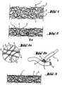
- the embodiment of the barrier material shown consists of a fiber composite 1 in the form of a thermally bonded and thermally bonded fleece.
- This fiber composite 1 consists of two fiber components 2, 3, which are each constructed, for example, with polyester fibers.
- a first fiber component 2, which serves as the carrier component of the fiber composite 1 has a higher melting temperature than the second fiber component 3, which serves as a strengthening component.
- polyester polymers that have different melting temperatures and softening temperatures below them.
- a polyester polymer with a melting temperature of approximately 230 ° C. is selected for the first component, while a polyester polymer with a melting temperature of approximately 200 ° C. is selected for at least one fiber portion of the second fiber component 3.
- the core 4 of this fiber component consists of a polyester with a softening temperature of approximately 230 ° C. and the sheath of this fiber component consists of polyester with an adhesive softening temperature of about 200 ° C ( Figure 2b ).
- Such a fiber component with two fiber components of different melting temperatures is also referred to as "bico" for short. This short term will also be used below.
- the fibers of the two fiber components are each staple fibers with the special properties mentioned above.
- the weight fraction of the first fiber component is about 50%.
- the weight fraction of the second fiber component is also about 50% based on the weight per unit area of the fiber composite.
- the fineness of the first fiber component is 6.7 dtex, whereas the second fiber component, which is designed as a bico, has a higher fineness of 4.4 dtex.
- the fiber components present as staple fibers are first mixed. Then several individual layers of this staple fiber mixture are placed on top of one another in the form of several individual nonwoven layers until the desired weight per unit area for the fiber composite is reached, whereby a nonwoven package is obtained.
- This fleece package has very little mechanical stability and therefore has to go through some consolidation processes.
- the nonwoven package is mechanically consolidated by needling using needle technology, with needle bars arranged in a needle matrix penetrating the nonwoven package perpendicular to the plane of extent of the nonwoven package.
- needle bars arranged in a needle matrix penetrating the nonwoven package perpendicular to the plane of extent of the nonwoven package.
- fibers of the nonwoven package are reoriented out of their original position in the nonwoven package, resulting in entanglement of fibers and a more stable mechanical structure of the nonwoven package.
- a nonwoven material mechanically consolidated by such needling is schematically shown in Figure 1 shown.
- the fiber composite according to the invention is treated further. Thereby thermal energy and pressure are used.
- the advantageous composition of the fiber mixture is used, a temperature being chosen for the thermal consolidation of the fiber mixture such that it melts at least in the range of the softening temperature of the adhesive at a lower melting temperature
- the jacket of the core-jacket bico lies in order to soften it to a viscous state to such an extent that the fiber components of the first fiber component, which are in the vicinity of the softened mass of the jacket of the respective bico, can be partially enclosed in this viscous mass.
- the two fiber components are permanently connected to one another without changing the basic structure and structure of the fleece.
- the advantageous properties of this fleece can continue to be used, in particular its good water vapor permeability, combined with a permanent mechanical stabilizing property.
- thermally bonded fleece is shown in a schematic representation in Figure 2 shown, wherein in Figure 2a a detailed view of a detail is shown on a greatly enlarged scale, in which adhesive connection points between individual fibers are represented by flat black spots, and Figure 2b shows an area of this detail on an even larger scale.
- thermal surface compression can also be carried out on at least one surface of the nonwoven material by simultaneously exposing this nonwoven material surface to pressure and temperature, for example by means of heated press plates or press rolls. The result is an even stronger consolidation than in the remaining volume of the nonwoven material and a smoothing of the thermally pressed surface.
- a fleece which is first mechanically consolidated by needling, then thermally consolidated and finally thermally surface-pressed on one of its surfaces is in Figure 3 represented schematically.
- the longitudinal expansion values and the transverse expansion values show the percentage by which the respective material expands when it is subjected to an expansion force of 50 N, 100 N or 150 N, respectively.
- the lower this longitudinal or transverse expansion the more stable the material and the more suitable it is as a barrier material. If the respective material is used as a barrier material to protect a membrane against the pushing through of foreign bodies such as stones, the puncture resistance is important.
- the abrasion resistance also called abrasion in the comparison table, is also important for the use of the respective material in a composite shoe sole.
- the comparison table shows that split split leather has a high tear strength, a relatively good resistance to tensile forces and a high puncture resistance, but that it only has a moderate abrasion resistance with wet samples and in particular a fairly moderate water vapor permeability.
- the only needle-bonded nonwoven materials are relatively light and have a high water vapor permeability value compared to leather, but have a relatively low resistance to stretching forces, have only a low puncture resistance and have only moderate abrasion resistance.
- the needle-bonded and thermally bonded fleece (material 4) has a lower basis weight than materials 2 and 3, and is therefore more compact.
- the water vapor permeability of material 4 is higher than that of material 2 and about the same as that of material 3, but almost three times as large as that of leather according to material 1.
- the longitudinal and transverse expansion resistances of material 4 are significantly higher than that of only needle-bonded nonwoven materials 2 and 3, and the longitudinal and transverse load until tearing is also significantly higher than with materials 2 and 3. Substantially higher than with materials 2 and 3 are also puncture resistance and abrasion resistance.
- the water vapor permeability of material 5 is still higher than that of material 4.
- material 5 is also superior to material 4, since it does not show any stretching when the longitudinal and transverse expansion forces of 50 N to 150 N are used.
- the tensile strength is higher with regard to longitudinal loading and lower than that of material 4 with regard to transverse loading.
- the puncture resistance is somewhat lower than that of material 4, which is caused by the smaller thickness of material 5.
- Material 5 has a particular superiority over all materials 1 to 4 with regard to the abrasion resistance.
- the comparison table thus shows that if the barrier material is dependent on high water vapor permeability, high dimensional stability and thus stabilizing effect and high abrasion resistance, material 4, in particular material 5, is very particularly suitable.
- the needle-bonded and thermally bonded nonwoven which already has very good stabilization, is subsequently subjected to a hydrophobicization equipment, for example by dipping in a liquid which brings about hydrophobicization, in order to minimize suction effects of the nonwoven material.
- a hydrophobicization equipment for example by dipping in a liquid which brings about hydrophobicization, in order to minimize suction effects of the nonwoven material.
- the fleece is dried under the influence of heat, the hydrophobic property of the applied equipment also being further improved.
- the fleece passes through a calibration plant, the final thickness of, for example, 1.5 mm being set.
- the fleece is then again subjected to temperature and pressure in order to remelt the meltable fiber components, namely in the jacket of the bico of the second fiber component, on the surface of the fleece and with the help of pressure applied at the same time against a very high pressure to press smooth surface.
- This is done either with suitable calendering devices or by means of a heated press unit, whereby a separating material layer, which is for example silicone paper or Teflon, can be inserted between the fleece and the heated press plate.
- the surface smoothing by thermal surface compression is carried out only on one surface or on both surfaces of the nonwoven material.
- the nonwoven fabric produced in this way has a high stability against tearing load and has a good puncture resistance, which is important when using the material as a barrier material to protect a membrane.
- the material 5 described above represents a first embodiment of the barrier material used according to the invention, in which both fiber components consist of polyester, both fiber components have a weight percentage of 50% each in the total fiber composite, and the second fiber component is a polyester core / sheath fiber is of the bico type.
- Barrier material in which both fiber components consist of polyester and each have a weight percentage of 50% of the entire fiber composite and the second fiber component is a side-by-side type polyester bico.
- the barrier material according to embodiment 2 is produced in the same way and has the same properties as the barrier material according to embodiment 1 with a bico-fiber of the core-sheath type.
- Barrier material in which both fiber components have a weight percentage of 50% each and the first fiber component consists of polyester and the second fiber component consists of polypropylene.
- a bicomponent fiber is used instead of a bico as the second fiber component.
- the polyester fiber with a melting point of approximately 230 ° C
- the polypropylene fiber with a weight fraction of also 50% has a lower melting point of approximately 130 ° C and thus the adhesive strengthening component represents.
- the manufacturing process is otherwise the same as in embodiment 1.
- the nonwoven fabric according to embodiment 3 has a lower thermal stability, but can also be produced using lower temperatures.
- Barrier material with a share of 80% polyester as the first fiber component and a polyester core-jacket bico as the second fiber component.
- Figure 4 shows a partial cross section through a composite shoe sole 21 with an outer sole 23 and an overlying shoe stabilization device 25 before this composite shoe sole 21 is provided with a barrier material.
- the outsole 23 and the shoe stabilization device 25 each have through openings 27 and 29, which overall form an opening 31 through the total thickness of the composite shoe sole 21.
- the opening 31 is thus formed by the intersection of the two through openings 27 and 29.
- Barrier material 33 (not shown) placed in the through opening 29 or arranged above this.
- Figure 5 shows an example of a barrier unit 35 with a piece of barrier material 33 which is enclosed by a stabilization device 25.
- the stabilization device is injection molded around or injected around a peripheral region of the piece of barrier material 33 such that the material of the stabilization device 25 penetrates into the fiber structure of the barrier material 33 and cures there and forms a firm bond.
- Thermoplastic polyurethane (TPU), for example, is suitable as the material for the encapsulation of the stabilization device or the injection molding onto the stabilization device, which leads to very good edging of the barrier material and bonds well with it.
- the barrier material 33 is glued to the stabilization device 25.
- the stabilization device 25 preferably has a stabilization frame that stabilizes at least the composite shoe sole 21 and at least one stabilization web 37 that is arranged on a surface of the barrier material 33.
- the at least one stabilizing web 37 is preferably arranged on an underside of the barrier material 33, which is directed towards the outsole.
- Figure 6 shows a barrier unit 35, in which a piece of barrier material 33 is enclosed by a stabilization device 25 in the sense that the edge region of the barrier material 33 is not only surrounded by the stabilization device 25, but is also overlapped on both surfaces.
- Figure 7 shows a barrier unit 35, in which a piece of barrier material 33 is provided with a stabilizing device 25 in the form of at least one stabilizing web 37.
- the stabilizing web 37 is arranged on at least one surface of the barrier material 33, preferably on the surface facing downward toward the outsole 23.
- Figure 8 shows a barrier unit 35, in which a piece of barrier material 33 is provided with a stabilizing device 25 such that the barrier material 33 is attached to at least one surface of the stabilizing device 25.
- the barrier material 33 covers the through opening 29.
- the stabilizing web 37 is located within the through opening 29 of the stabilizing device 25.
- Figure 9 shows a composite shoe sole 21 according to Figure 4 which according to a barrier unit above the outsole 23 Figure 5 has, with only a stabilizing web 37 is shown.
- the connecting material not only adheres to the surfaces to be connected, but penetrates into the fiber structure and hardens there when sprayed, extrusion-coated or glued between the barrier material 33 and the stabilizing device 25.
- the fiber structure is thus additionally reinforced in its connection area.
- FIG. 10 and 11 Two embodiments of stabilization web patterns of stabilization webs 37 applied to a surface of the barrier material 33 are shown. While in the case of Figure 10 On a circular surface 43, for example the underside of the barrier material 33, which corresponds, for example, to an opening in the composite shoe sole 21, three individual webs 37a, 37b and 37c are arranged in a T-shaped mutual arrangement, for example by gluing to the underside of the barrier material, in the case of Figure 11 a stabilizing web device in the form of a stabilizing grid 37d is provided.
- Figure 12 shows a perspective oblique view from below of an embodiment of a shoe 101 according to the invention with a shaft 103 and a composite shoe sole 105 according to the invention.
- the shoe 101 has a forefoot area 107, a metatarsal area 109, a heel area 111 and a foot insertion opening 113.
- the shoe sole composite 105 has on its underside a multi-part outsole 117, which has an outsole part 117a in the heel area, an outsole part 117b in the ball area and an outsole part 117c in the toe area of the composite shoe sole 105.
- outsole parts 117 are fastened to the underside of a stabilization device 119, which has a heel area 119a, a midfoot area 119b and a forefoot area 119c.
- the composite shoe sole 105 will be explained in more detail with reference to the following figures.
- Further components of the composite shoe sole 105 can be damping sole parts 121a and 121b, which are applied in the heel area 111 and in the forefoot area 107 on the upper side of the stabilization device 119.
- the outsole 117 and the stabilization device 119 each have through openings which form openings through the composite shoe sole. These openings are covered by barrier material parts 33a-33d in a water vapor permeable manner.
- Figure 13a shows the shoe 101 according to Figure 12 in a manufacturing stage in which the upper 103 and the shoe sole compound 105 are still separated from one another.
- the shaft 103 is provided on its sole-side lower end region with a shaft bottom 221, which has a waterproof, water vapor-permeable shaft bottom functional layer, which can be a waterproof, water vapor-permeable membrane.
- the functional layer is preferably part of a multi-layer functional layer laminate which, in addition to the functional layer, has at least one support layer, for example a textile backing, as processing protection.
- the shaft base 115 can be provided with a shaft mounting sole. However, it is also possible to assign the function of a shaft mounting sole to the functional layer laminate.
- the composite shoe soles already shows in Figure 8 mentioned openings 31, which are covered with barrier material parts 33a-33d.
- the webs 37 are shown within the peripheral edge of the respective openings.
- three openings or two openings or one opening can be provided.
- more than four openings are provided.
- the shoe sole composite 105 can be attached to the sole end of the shaft either by injection or by gluing, in accordance with the state Figure 12 to manufacture.
- Figure 13b shows the same shoe construction as in Figure 13a , with the difference that the shoe in Figure 13a has four openings 31, while the shoe after Figure 13b is equipped with two openings 31. It can be seen here that the webs 37 are arranged within the peripheral edge of the respective opening 31 and do not form a boundary of the opening 31. The area of an opening is determined minus the total area of the webs crossing it, since this web area blocks the water vapor transport.
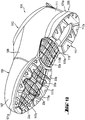
- Figure 14 shows a composite shoe sole 105 with an upper side remote from the outsole 117.
- the stabilization device 119 is covered in its central region 119b and in its forefoot region 119c with a plurality of pieces 33a, 33b, 33c and 33d of a barrier material 33, with which in FIG Figure 14 Openings of the composite shoe sole 105 that are not visible are covered.
- a damping sole part 121a or 121b is applied to the top of the stabilization device 119, in the heel area essentially over the entire area and in the forefoot area with recesses where the barrier material parts 33b, 33c and 33d are located.
- the outsole parts of the outsole 117, the stabilization device 119 and the damping sole parts 121a and 121b have different functions within the composite shoe sole, they are expediently also constructed with different materials.
- the outsole parts which are said to have good abrasion resistance, consist for example of a thermoplastic polyurethane (TPU) or rubber.
- Thermoplastic polyurethane is the generic term for a large number of different polyurethanes, which can have different properties.
- a thermoplastic polyurethane with high stability and slip resistance can be selected for an outsole.
- the cushioning sole parts 121a and 121b which are intended to provide shock absorption for the user during the walking movements, are made of a correspondingly resilient material, for example ethylene vinyl acetate (EVA) or polyurethane (PU).
- EVA ethylene vinyl acetate
- PU polyurethane
- the stabilization device 119 which for the non-contiguous outsole parts 117a, 117b, 117c and for the likewise Non-contiguous damping sole parts 121a, 121b serves as a holder and for the entire shoe sole bandage 105 as a stabilizing element and should have a corresponding elastic rigidity, for example consists of at least one thermoplastic.
- thermoplastics examples include polyethylene, polyamide, polyamide (PA), polyester (PET), polyethylene (PE), polypropylene (PP) and polyvinyl chloride (PVC).
- suitable materials are rubber, thermoplastic rubber (TR, from Thermoplastic Rubber) and polyurethane (PU). Thermoplastic polyurethane (TPU) is also suitable.
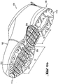
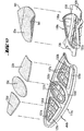
- the in Figure 14 shown shoe sole compound is in Figure 15 shown in an exploded view, ie in a view in which the individual parts of the composite shoe sole 105 are shown separately from one another, with the exception of the barrier material parts 33a, 33b, 33c and 33d, which are shown as already arranged on the stabilizer parts 119b and 119c.
- the stabilization device 119 has its parts 119a, 119b and 119c as initially separate parts which are connected to one another to form the stabilization device 119 during the assembly of the shoe sole assembly 105, which can be done by welding or gluing the three stabilization device parts together.
- FIG. 16 As still related to Figure 16 will be explained, are below the barrier material parts openings, which together with openings 123a, 123b and 123c in the outsole parts 117a, 117b and 117c openings 31 of FIG Figure 4 form already explained and are covered with the barrier material parts 33a-33d in a water vapor permeable manner.
- a through opening 125 in the heel part 119a of the stabilizing device 119 is not closed with barrier material 33, but with the full-surface damping sole part 121a. This achieves a better damping effect of the composite shoe sole 105 in the heel area of the shoe, where sweat moisture removal may be less necessary under certain circumstances, since foot sweat mainly forms in the forefoot and midfoot area, but not in the heel area.
- the damping sole part 121b is provided with through openings 127a, 127b and 127c, which are dimensioned such that the barrier material parts 33b, 33c, 33d within a bordering edge 129a, 129b and 129c of the stabilizing device part 119c in the through openings 127a, 127b and 127c, respectively can be included.
- no damping sole part 121 is provided.
- the parts of the stabilization device 119a, 119b and 119c have a flat surface without a boundary edge 129a, 129b, 129c, so that the barrier material 33 is placed flush with the surface of the stabilization device in its openings.
- the composite sole is formed only by the barrier unit, made up of barrier material 33 and stabilizing device 119, and the outsole.
- openings 135a, 135b, 135c and 135d can be seen in the stabilizing device parts 119b and 119d, which are covered with the associated barrier material part 33a, 33b, 33c and 33d in a water-vapor-permeable manner, with the openings 31 ( Figure 4 ) of the shoe sole composite 105 are closed in a water vapor permeable manner.
- the barrier material parts are arranged such that their smooth surface faces the outsole.
- the openings 135a to 135d are each bridged by a stabilizing grid 137a, 137b, 137c and 137e, which each form a stabilizing structure in the region of the associated opening of the stabilizing device 119.
- these stabilizing grids 137a-137e act against the penetration of larger foreign objects up to the barrier material 33 or even further, which could be felt uncomfortably by the user of the shoe.
- connecting elements 139 provided on the axial ends of the stabilizer part 119b on the midfoot side, which overlap when the stabilizer 119 is assembled from the three stabilizer parts 119a to 119c on the upper sides of the stabilizer parts 119a and 119c facing away from the outsole attachment side come to rest to be fixed there, for example by welding or gluing.
- Figure 17 shows in opposite Figure 16 enlarged representation of the two stabilizer parts 119a and 119b before they are attached to one another, the openings 135b to 135d of the forefoot-side stabilizer part 119c and the stabilizing grid structures located therein being particularly clearly visible.
- the middle stabilizer part 119b shows frame and lattice parts bent up on the long sides.
- the piece of barrier material 33a to be placed on the stabilizing device part 119b is provided on its longitudinal sides with correspondingly bent-up side wings 141. These bent-up parts of both the shoe stabilization part 119b and the barrier material piece 33a adapt to the shape of the lateral metatarsal flanks.
- the remaining barrier material parts 33b to 33d are essentially flat, corresponding to the essentially flat design of the stabilizer device part 119c on the forefoot side.
- the at least one opening 135a-135d of the stabilization device 119b and 119c is delimited by the frame 147 of the stabilization device 119 and not by the webs 37 present in the openings 135a-135d.
- Limiting edges 129a-129c shown in this embodiment form part of the respective frame 147.
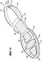
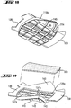
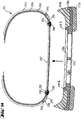
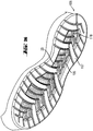
- FIGS Figures 18 and 19 A further modification of the barrier unit part provided for the midfoot area with the stabilization device part 119b and the barrier material part 33a is shown in FIGS Figures 18 and 19 shown in Figure 18 in the fully assembled state and in Figure 19 while these two parts are still separate.
- the stabilization device part 119b provided for the midfoot area is provided only in the middle area with an opening and a stabilization grid 137a located therein, while the two wing parts 143 on the long sides of the stabilizing device part 119b are continuous, that is to say have no opening, but are only provided with stabilizing ribs 145 on their underside.
- the piece of barrier material 33a provided for this barrier unit part is narrower than in the variants of FIG Figures 18 to 19 because it is not the side wings 141 according to the Figure 17 needed.
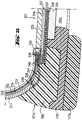
- FIG Figures 20 to 27 Embodiments and details of inventive footwear explained, which is constructed with a composite shoe sole according to the invention.
- the show Figures 20 , 22 and 23 an embodiment of the footwear according to the invention, in which the shaft bottom has a shaft mounting sole and additionally a functional layer laminate
- the Figures 24 and 25th show an embodiment of footwear according to the invention, in which a shaft bottom functional layer laminate 237 simultaneously takes over the function of a shaft mounting sole 233.
- the Figure 26 shows a further embodiment of the composite shoe sole 105.
- the two embodiments shown have the shoe 101 in accordance with the Figures 12 and 13a-b a shaft 103 which has an outer material layer 211 located on the outside, an inner lining layer 213 and a waterproof, water-vapor-permeable shaft functional layer layer 215 located between them, for example in the form of a membrane.
- the shaft functional layer layer 215 can be present in combination with the lining layer 213 as a 2-layer laminate or as a 3-layer laminate, the shaft function layer layer 215 being embedded between the lining layer 213 and a textile side 214.
- the upper shaft end 217 is dependent on whether the cutting plane the one in the Figures 20 and 24th cross-sectional view shown is in the forefoot area or in the midfoot area, closed or to the foot insertion opening 113 ( Figure 12 ) open.
- the shaft 103 On the sole-side shaft end region 219, the shaft 103 is provided with a shaft bottom 221, by means of which the lower end of the shaft 103 on the sole side is closed.
- the shaft bottom 221 has a shaft mounting sole 233, which is connected to the sole-side shaft end region 219, which in the embodiments according to FIGS Figures 20 to 25 happens by means of a strobe seam 235.
- a shaft bottom functional layer laminate 237 is provided, which is arranged below the shaft mounting sole 233 and extends beyond the circumference of the shaft mounting sole 233 into the sole-side shaft end region 219.
- the shaft bottom functional layer laminate 237 can be a 3-layer laminate, the shaft bottom functional layer 248 is embedded between a textile backing and another textile layer. It is also possible to provide the shaft bottom functional layer 247 only with the textile backing.
- the sole end region 219 of the upper material layer 211 is shorter than the upper functional layer layer 215, so that there is a protrusion of the upper functional layer layer 215 from the upper material layer 211 and the outer surface of the upper functional layer layer 215 is exposed.
- a net band 241 or another material penetrable for sealing material is arranged between the sole-side end 238 of the upper material layer 211 and the sole-side end 239 of the shaft functional layer layer 215, the longitudinal side thereof remote from the strobe seam 235 by means of a first seam 243 is connected to the sole-side end 238 of the upper material layer 211, but not to the shaft functional layer layer 215, and its long side facing the strobe seam 235 is connected to the sole-side end 239 of the shaft functional layer layer 215 and to the shaft mounting sole 233 by means of the strobe seam 235.
- the net tape 241 is preferably made of a monofilament material so that it has no water conductivity.
- the mesh tape is preferably used for molded soles. If the sole composite is attached to the shaft by means of adhesive, instead of the net tape, the end 238 of the upper material layer 211 on the sole side can be attached to the lasting function layer laminate by means of adhesive 249 ( Figure 22 ).
- a sealing material 248 is arranged between the upper floor functional layer laminate 237 and the sole-side end 239 of the upper functional layer layer 215, by means of which a waterproof connection between the sole-side end 239, the upper functional layer 215 and the peripheral region 245 of the shaft bottom functional layer laminate 237 is produced, this seal acting through the mesh band 241.
- the in the Figures 20 , 23 to 25 The net tape solution shown serves to prevent water that runs down or crawls down the upper material layer 211 from reaching the strobing seam 235 and from there penetrating into the shoe interior. This is prevented by the fact that the sole-side end 238 of the upper material layer 211 ends at a distance from the sole-side end 239 of the shaft functional layer layer 215, which is bridged with the non-water-conducting mesh tape 241, and the sealing material 247 is provided in the region of the protrusion of the shaft functional layer layer 215.
- the network band solution is known per se from the document EP 0298360 B1 .
- connection technologies used in the shoe industry can be used for the preferably watertight connection of the upper to the upper.
- the network tape solution shown and the tweaked solution in Figure 22 are exemplary embodiments.
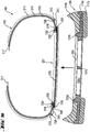
- a shoe sole assembly 105 of the same construction can be used, as shown in these two figures. Because in the Figures 20 and 24th Shown are sectional views of the shoe 101 in the forefoot area, these figures show a sectional view of the forefoot area of the composite shoe sole 105, that is to say a sectional view along a transverse cutting line through the stabilization unit part 119c intended for the forefoot area with the barrier material piece 33c inserted in its opening 135c .
- the sectional view of the composite shoe sole 105 shows the stabilizing device part 119c with its opening 135c, a web of the associated stabilizing grid 137c bridging this opening, the upstanding frame 129b, the piece of barrier material 33c inserted in this frame 129b, the damping sole part 121b on the upper side of the stabilizing device part 119c and the outsole part 117b on the underside of the stabilizer part 119c.
- both embodiments of the Figures 20 and 24th match.
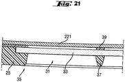
- Figure 21 shows an example of a barrier unit 35, in which a piece of barrier material 33 is provided on its underside with at least one stabilizing web 37.
- an adhesive 39 is applied to the surface area of the barrier material 33 opposite the stabilizing web 37, via which the adhesive material 33 is connected to the waterproof, water-vapor-permeable upper 221 of the shoe, which is located outside the composite shoe sole above the barrier unit 35.
- the adhesive 39 is applied in such a way that the shaft bottom 221 remains unconnected to the barrier material 33 wherever there is no material of the stabilizing web 37 on the underside of the barrier material 33. In this way it is ensured that the water vapor permeability function of the shaft bottom 115 is only disturbed by adhesive 39 where the barrier material 33 cannot permit water vapor transport anyway due to the arrangement of the stabilizing web 37.
- the upper surface functional layer 247 of the upper functional layer laminate 237 is preferably a microporous functional layer in all embodiments, for example made of stretched polytetrafluoroethylene (ePTFE).
- ePTFE stretched polytetrafluoroethylene
- Figure 22 shows an embodiment in which the sole composite 105 according to the invention is fastened to the shaft base by means of fastening adhesive 250.
- the shaft functional layer laminate 216 is a three-layer composite with a textile layer 214, a shaft functional layer 215 and a lining layer 213.
- the end 238 of the upper material layer 211 on the sole side is fastened to the upper functional layer laminate 216 with lasting adhesive 249.
- the fastening adhesive 250 is applied to the surface of the composite sole with the exception of the openings 135 and the barrier material 33 arranged in the region of the openings 135.
- the fastening adhesive 250 penetrates up to and partially into the shaft functional layer laminate 216 and also to and partly in edge areas of the shaft bottom functional layer laminate 237.
- Figure 23 is an illustration of the shaft construction according to Figure 20 with a molded shoe sole compound.
- the three-layer upper layer functional layer laminate 237 is attached to the upper sole 233 in such a way that the textile side 246 faces the composite sole. This is advantageous because the sole injection material 260 can more easily penetrate into the thin textile side and anchor there, thus creating a firm connection to the shaft bottom functional layer 237.
- the barrier unit with the at least one opening 135 and the at least one piece of barrier material 33 is in the form of a prefabricated unit and is inserted into the injection mold before the injection process.
- the sole injection material 260 is correspondingly injection-molded onto the shaft bottom, whereby it penetrates through the mesh band 241 to the shaft functional layer laminate 216.
- Figure 25 shows an enlarged and partial view of the Figure 24 .
- the sole composite 105 shows a further embodiment of the barrier unit 35 according to the invention.
- the shoe stabilization device 119c forms part of the sole composite 105 and does not extend here to the outer circumference of the sole composite 105.
- a piece of barrier material 33c is above the opening 135 attached in such a way that the material 33c rests on the circumferential, continuously planar boundary edge 130 of the opening 135.
- the sole composite 105 can be attached to the shaft bottom 221 with fastening adhesive 250 or can be injection molded with sole injection material 260 (as shown).
- Figure 25 also clearly shows that in the embodiment in which the shaft bottom functional layer laminate 237 also takes over the function of the shaft mounting sole 233, the laminate comes to lie directly above the opposite upper side of the piece of barrier material 33c, which is particularly advantageous.
- no air cushion can form between the shaft bottom functional layer laminate 237 and the barrier material piece 33c, which could impair the water vapor removal, and the barrier material piece 33c and in particular the shaft bottom functional layer 247 is particularly close to the sole of the foot of the user of such a shoe, which improves the water vapor removal , which is determined by the existing temperature gradient between the interior and exterior of the shoe.
- Figure 26 is a representation of a further embodiment of the composite sole according to the invention.
- the perspective illustration shows a plurality of openings 135 in the shoe stabilization device 119, which are arranged from the toe region to the heel region of the composite sole.
- the stabilizing material 33 is also present in the heel area.
- the outsole forms the outsole parts 117.
- Figure 27 is a representation of a further embodiment of the composite sole according to the invention in cross-sectional representation.
- the sole composite 105 of this embodiment is in Figure 24 sole composite shown quite similar.
- the sole composite 105 according to Figure 27 has an outsole, a cross section through the ball area of the sole composite 105 being shown in this figure and therefore a cross section through the corresponding outsole part 117b.
- the teaching according to Figure 27 but also applies to the other areas of the composite sole 105, that is to say also to the middle part of the foot and the heel part thereof.
- the outsole part 117b has a tread 153, which touches the floor when walking.
- the sectional view of the composite sole 105 of Figure 27 shows the stabilizer part 119c with its opening 135c, its upwardly projecting boundary edge 129b, the piece of barrier material 33c inserted into the boundary edge 129b, the damping sole part 121b on the upper side of the stabilizer part 119c and the outsole part 117b on the underside of the stabilizer part 119c.
- a support element 151 is attached to the underside of the barrier material piece 33c. This extends from the side of the barrier material 33 facing the tread to the level of the tread 153 in such a way that the barrier material 33 is supported on the walked floor when it is run over the support element 151.
- an in Figure 27 lower free end of the support element 151 when the shoe provided with this sole composite stands on a surface, touches this surface.
- the piece of barrier material 33c is essentially in its shape when walking on such a surface Figure 27 shown position held so that its bending under the load of a user of the shoe is avoided.
- a plurality of support elements 151 can be arranged in the opening 135c in order to increase the support effect for the piece of barrier material 33c and to make it more uniform over its surface extension.
- the support function can also be obtained by using the in Figure 24 Stabilizing web 137c shown forms at the same time as a support element 151 by not allowing the stabilizing web 137c to end at a distance from the underside of the outsole part 117b which serves as the tread, but rather to extend to the level of this underside.
- the in Figure 10 The stabilizing webs 37c shown or the stabilizing grid 37d shown in FIG. 11 are designed entirely or partially as support elements 151.
- a high water vapor permeability value is achieved because, on the one hand, large openings are provided in the shoe sole assembly 105 and these are closed with material of high water vapor permeability and because, at least in the area of the openings 31, there is no connection between the water vapor permeable barrier material 33 and the water vapor exchange barrier There is a shaft bottom functional layer 247 and such a connection exists at most in the areas outside the openings 31 of the composite shoe sole 105 which are not actively involved in the water vapor exchange are, for example, the edge regions of the composite shoe sole 105.
- the upper layer 247 of the shaft bottom is arranged close to the foot, which leads to an accelerated removal of water vapor.
- the shaft bottom functional layer laminate 237 can be a multilayer laminate with two, three or even more layers. At least one functional layer is included with at least one textile carrier for the functional layer, wherein the functional layer can be formed by a waterproof, water vapor permeable membrane 247, which is preferably microporous.
- the thickness of the barrier material according to the invention is tested according to DIN ISO 5084 (10/1996).
- the puncture resistance of a textile fabric can be measured using a measurement method used by EMPA (Swiss Federal Materials Testing and Research Institute) using a test device from the Instron tensile testing machine (model 4465).
- EMPA Esphalon tensile testing machine
- a round piece of textile with a diameter of 13 cm is punched out using a punching iron and attached to a support plate in which there are 17 holes.
- the force to pierce the textile piece is measured using a load cell (a force transducer). The result is determined from a number of samples of three samples.
- a functional layer is regarded as "watertight", possibly including seams provided on the functional layer, if it guarantees a water inlet pressure of at least 1x10 4 Pa.
- the functional layer material preferably ensures a water inlet pressure of over 1x10 5 Pa.
- the water inlet pressure is to be measured according to a test procedure in which distilled water is applied at 20 ⁇ 2 ° C to a sample of 100 cm2 of the functional layer with increasing pressure. The pressure rise of the water is 60 ⁇ 3 cm Ws per minute. The water inlet pressure then corresponds to the pressure at which water first appears on the other side of the sample. Details of the procedure are given in the ISO standard 0811 from 1981.
- Whether a shoe is waterproof for example, with a centrifuge arrangement in the US-A-5,329,807 described type can be tested.
- the water vapor permeability values of the barrier material according to the invention are tested using the so-called cup method according to DIN EN ISO 15496 (09/2004).
- a functional layer is considered to be "water vapor permeable” if it has a water vapor permeability number Ret of less than 150 m2 ⁇ Pa ⁇ W -1 .
- the water vapor permeability is tested according to the Hohenstein skin model. This test method is described in DIN EN 31092 (02/94) and ISO 11092 (1993).
- the shoe bottom structure has a water vapor permeability (MVTR from Moisture Vapor Transmission Rate) in the range from 0.4 g / h to 3 g / h , which can range from 0.8 g / h to 1.5 g / h and, in a practical embodiment, is 1 g / h.
- MVTR Water vapor permeability
- the degree of water vapor permeability of the shoe bottom structure can be compared with that in the document EP 0396716 B1 specified measurement method can be determined, which has been designed to measure the water vapor permeability of an entire shoe.
- the measurement method can be used to measure the water vapor permeability of only the base of a shoe EP 0 396 716 B1 can also be used by using the in Fig. 1 the EP 0 396 716 B1 shown measurement structure is measured in two successive measurement scenarios, namely once the shoe with a water vapor permeable shoe bottom structure and another time the otherwise identical shoe with a water vapor impermeable shoe bottom structure. From the difference between the two measured values the proportion of water vapor permeability can then be determined, which is due to the water vapor permeability of the water vapor permeable shoe bottom structure.
- the water vapor permeability value for the water vapor permeable shoe bottom structure can be determined from the Determine the difference AB.
- abrasion resistance for the abrasion measurements to obtain the abrasion values in the comparison table
- two measurement methods have been used. On the one hand, it was tested with a Martindale abrasion tester (in the "Abrasion Carbon” table), which was tested according to the standard DIN EN ISO 124947 -1; -2; (04/1999) the sample to be tested is scrubbed against sandpaper. There were three deviations from the standard: First, sandpaper with a grain size of 180 plus standard foam was clamped in the sample holder. Second, standard felt plus the test sample was clamped in the sample table. Third, the sample was inspected on all 700 tours and the sandpaper was replaced.
- Lissajous figures represent an overall picture that repeats periodically and is composed of individual figures that are offset relative to one another. The passage through one of these individual figures is referred to as a tour in connection with the abrasion test. For all materials 1 to 5, it was measured after how many tours first holes had occurred in the respective material, that is to say the respective material had been worn through. In the comparison table there are two trip values for each of the materials, which resulted from two abrasion tests with the same material.
- Shore hardness is understood as the resistance to the penetration of a body of a certain shape under a defined spring force.
- the Shore hardness is the difference between the numerical value 100 and the penetration depth of the indenter divided by the scale value 0.025 mm in mm under the effect of the test force.
- the indenter In the Shore A test, a truncated cone with an opening angle of 35 ° is used as the indenter, and in Shore D a cone with an opening angle of 30 ° and a tip radius of 0.1 mm is used.
- the indenters are made of polished, hardened steel.
- Material that protects the shoe or the parts / materials in the shoe such as the upper material, sole, membrane, mechanical protection and resistance to deformation as well as the penetration of external objects / foreign bodies / objects e.g. through the sole while maintaining a high water vapor transport, i.e. a high level of climate comfort in the shoe.
- the mechanical protection and resistance to deformation is mainly due to the low elongation of the barrier material.
- the generic term for a composite of fibers of all kinds includes leather, nonwovens or knitted fabrics made of metal fibers, possibly also in a mixture with textile fibers, also yarns and textiles (fabrics) made from yarn.
- the fiber composite must have at least two fiber components. These components can be fibers (e.g. staple fibers), filaments, fiber elements, yarns, strands and the like. act. Each fiber component either consists of one material or contains at least two different material components, whereby one fiber component softens / melts at a lower temperature than the other fiber component (Bico).
- Such bico fibers can have a core-sheath structure - here a core fiber portion is sheathed with a sheath fiber portion -, a side-by-side structure or an island-in-sea structure. Such processes and machines for this are available from Rieter Ingolstadt, Germany and / or Schalfhorst in Mönchengladbach, Germany.
- the fibers can be simply spun, multifilamentary or several torn fibers with intertwined frayed ends.
- the fiber components can be distributed evenly or unevenly in the fiber composite.
- the entire fiber composite must preferably be temperature stable at at least 180 ° C.
- a uniform and smooth surface on at least one side of the fiber composite is achieved by means of pressure and temperature. This smoothed surface points "down" to the ground / floor, so that particles / foreign bodies bounce better on the smooth surface or are rejected more easily.
- the properties of the surface or the overall structure of the fiber composite or stabilizing material depend on the fibers selected, the temperature, the pressure and the period over which the fiber composite was subjected to temperature and pressure.
- the fibers are placed on a conveyor belt and tangled.
- Sheets made with warp and weft threads made with warp and weft threads.
- the melting temperature is the temperature at which the fiber component or the fiber portion becomes liquid.
- the melting temperature in the field of polymer or fiber structures is understood to be a narrow temperature range, in which the crystalline areas of the polymer or fiber structure melt and the polymer changes into the liquid state. It lies above the softening temperature range and is an essential parameter for partially crystalline polymers. Melted means the change in the state of matter of the fiber or parts of the fiber at a characteristic temperature from solid to viscous / flowable.
- the second fiber component or the second fiber portion only has to become soft / plastic, but not liquid. I.e. the softening temperature used is below the melting temperature at which the component / portion dissolves.
- the fiber component or parts thereof are preferably softened in such a way that the more temperature-stable component is embedded or bound in the softened parts.
- the first softening temperature range of the first fiber component is higher than the second softening temperature range of the second fiber component or the second fiber component of the second fiber component.
- the lower limit of the first softening range can be below the upper limit of the second softening range.
- the adhesive softening temperature can also be selected such that the fibers of the second fiber component are softened to such an extent that the fibers of the second fiber component are not only bonded to one another Rather, a partial or complete sheathing of individual points of the fibers of the first fiber composite with softened material of the fibers of the second fiber composite occurs, i.e. a partial or complete embedding of such points of fibers of the first fiber composite in the material of fibers of the second fiber component that a correspondingly increased Stabilization strengthening of the fiber composite occurs.
- the barrier material must be temperature-stable for the injection. The same applies to injection molding (approx. 170 ° C - 180 ° C) or vulcanization of the shoe sole. If the stabilization device is to be injection molded, the barrier material must have a structure such that the stabilization device can at least penetrate into the structure of the barrier material or, if necessary, penetrate it.
- the shaft bottom functional layer and optionally the shaft functional layer can be formed by a waterproof, water vapor-permeable coating or by a waterproof, water vapor-permeable membrane, which can either be a microporous membrane or a membrane without pores.
- the membrane comprises stretched polytetrafluoroethylene (ePTFE).
- Suitable materials for the waterproof, water vapor-permeable functional layer are in particular polyurethane, polypropylene and polyester, including polyether esters and their laminates, as described in the publications US-A-4,725,418 and US-A-4,493,870 are described.
- stretched microporous polytetrafluoroethylene ePTFE
- ePTFE stretched microporous polytetrafluoroethylene
- the average pore size is between about 0.2 microns and about 0.3 microns. Pore size can be measured using the Coulter Porometer (trade name) manufactured by Coulter Electronics, Inc., Hialeath, Florida, USA.
- the barrier unit is formed by the barrier material and optionally by the stabilization device in the form of at least one web and / or a frame.
- the barrier unit can be in the form of a prefabricated component.
- the composite shoe sole consists of barrier material and at least one stabilizing device and at least one outsole and, if appropriate, further sole layers, the barrier material closing off the at least one opening which extends through the composite shoe sole thickness.
- a breakthrough is the area of the composite shoe sole through which water vapor can be transported.
- the outsole and the stabilization device each have through-openings which form an overall opening through the total thickness of the composite shoe sole.
- the opening is thus formed by the intersection of the two through openings. Any webs that may be present are arranged within the peripheral edge of the respective opening and do not form a boundary of the opening.
- the area of a breakthrough is determined minus the area of all webs crossing it, since this web surface blocks the water vapor transport and therefore does not represent a breakthrough area.
- the stabilization device acts as additional stabilization of the barrier material, is shaped and attached to the barrier material in such a way that the water vapor permeability of the barrier material is only slight, if at all is influenced. This is achieved in that only a small area of the barrier material is covered by the stabilization device.
- the stabilizing device is preferably directed downward toward the floor. In the first place, the stabilization device is not a protective function, but rather to serve as stabilization.
- the at least one opening of the stabilization device is limited by its at least one frame.
- the area of an opening is determined minus the area of all webs crossing it.
- Footwear consisting of a composite shoe sole and a closed upper (shaft).
- the bottom of the shoe covers all layers below the foot.
- Thermal activation takes place by applying energy to the fiber composite, which leads to an increase in the temperature of the material up to the softening temperature range.
- a composite shoe sole is tested according to the centrifuge arrangement in the US-A-5,329,807 described type. Before testing, it must be ensured that any existing shaft bottom functional layer is made water-permeable. A water-permeable composite shoe sole is assumed if this test is not passed. If necessary, the test is carried out with colored liquid in order to indicate the path of the liquid through the composite shoe soles.
- Laminate is a composite consisting of a waterproof, water vapor-permeable functional layer with at least one textile layer.
- the at least one textile layer also referred to as backing, serves primarily to protect the functional layer during its processing.
- a 3-layer laminate consists of a waterproof, water vapor-permeable functional layer, which is embedded between two textile layers, whereby a punctiform adhesive can be applied between these layers.
- a functional layer is regarded as "watertight", possibly including seams provided on the functional layer, if it guarantees a water inlet pressure of at least 1x10 4 Pa.
- the top of the composite shoe sole is to be understood as the surface of the composite shoe sole which lies opposite the bottom of the upper.
- the outsole is to be understood as the part of the composite shoe sole that touches the bottom / lower degree or makes the main contact with the floor / bottom.
Description
Die Erfindung betrifft einen Schuhsohlenverbund, damit aufgebautes Schuhwerk sowie ein Verfahrung zur Herstellung von solchem Schuhwerk.The invention relates to a composite shoe sole, footwear constructed therewith and a procedure for the manufacture of such footwear.
Die Notwendigkeit, sich alternativ entweder für einen wasserdichten, jedoch Schwitzfeuchtigkeit stauenden oder für einen für Schwitzfeuchtigkeit durchlässigen jedoch auch wasserdurchlässigen Schuhbodenaufbau entscheiden zu müssen, besteht nicht mehr, seit es Schuhbodenaufbauten gibt, die trotz Wasserdampfdurchlässigkeit wasserdicht sind, und zwar aufgrund der Verwendung einer perforierten oder mit Durchbrechungen versehenen Laufsohle und einer darüber angeordneten wasserdichten, wasserdampfdurchlässigen Funktionsschicht, beispielsweise in Form einer Membran. Beispiele zeigen die Dokumente
Da der menschliche Fuß eine starke Schwitzneigung hat, geht das Bestreben der vorliegenden Erfindung dahin, Schuhwerk verfügbar zu machen, das einen Schuhbodenaufbau mit einer besonders hohen Wasserdampfdurchlässigkeit aufweist, ohne dessen Stabilität zu stark zu beeinträchtigen.Since the human foot has a strong tendency to sweat, the aim of the present invention is to provide footwear which has a shoe bottom structure with a particularly high water vapor permeability without impairing its stability too much.
Bei Schuhwerk mit einer Laufsohle mit klein bemessenen Durchbrechungen gemäß
Sohlenaufbauten gemäß
Ähnlich verhält es sich bei Sohlenaufbauten gemäß
Eine bessere Stabilisierung des Schuhbodenaufbaus ist bei einem Sportschuh gemäß
Andere Lösungen, beispielsweise gemäß
Bei Ausführungsformen der
Bei einer anderen Ausführungsform der
Es ist heutzutage bei der Herstellung von Schuhwerk gängige Arbeitsteilung, dass ein Hersteller den Schuhschaft herstellt und ein anderer Hersteller für die Herstellung der zugehörigen Schuhsohle oder des zugehörigen Schuhsohlenverbunds oder für deren Anspritzen an den Schuhschaft zuständig ist. Da die Hersteller für Schuhsohlen üblicherweise weniger für den Umgang mit wasserdichten, wasserdampfdurchlässigen Membranen ausgerüstet und erfahren sind, sind Schuhbodenkonzepte anstrebenswert, bei welchen der Schuhsohlenverbund als solcher frei von einer Membran ist und die Membran einen Teil des Schaftbodens bildet, an dem der Schuhsohlenverbund angeordnet wird.It is common today in the manufacture of footwear that one manufacturer produces the upper and another manufacturer is responsible for the production of the associated shoe sole or the associated composite shoe sole or for their injection molding onto the shoe upper. Since the manufacturers of shoe soles are usually less equipped and experienced to deal with waterproof, water vapor-permeable membranes, shoe bottom concepts in which the shoe sole compound as such is free of a membrane and the membrane forms part of the upper of the shaft on which the shoe sole compound is arranged are desirable .
Es ist daher eine Aufgabe der vorliegenden Erfindung, Schuhwerk, das einen Schuhbodenaufbau mit dauerhafter Wasserdichtigkeit und mit einer besonders hohen Wasserdampfdurchlässigkeit aufweist, vorzugsweise unter Erlangung einer möglichst hohen Stabilität des Schuhbodenaufbaus, einen dafür geeigneten Schuhsohlenverbund sowie ein Verfahren zur Herstellung von Schuhwerk verfügbar zu machen.It is therefore an object of the present invention to provide footwear which has a shoe bottom structure with permanent watertightness and with a particularly high water vapor permeability, preferably while attaining the highest possible stability of the shoe bottom structure, a suitable composite shoe sole and a method for producing footwear.
Zur Lösung dieser Aufgabe macht die Erfindung verfügbar Schuhwerk gemäß Patentanspruch 1 und ein Verfahren zur Herstellung von Schuhwerk gemäß Patentanspruch 14. Weiterbildungen dieser Gegenstände sind in den je zugehörigen abhängigen Ansprüchen angegeben.To achieve this object, the invention makes available footwear according to claim 1 and a method for manufacturing footwear according to
Gemäß einem ersten Aspekt der Erfindung wird ein wasserdampfdurchlässiger Schuhsohlenverbund mit einer Oberseite verfügbar gemacht, der mindestens eine sich durch die Schuhsohlenverbunddicke hindurch erstreckende Durchbrechung aufweist. Es ist eine Barriereeinheit vorgesehen mit einer mindestens teilweise die Oberseite des Schuhsohlenverbundes bildenden Oberseite und mit einem als Barriere gegen ein Hindurchdrücken von Fremdkörpern ausgebildeten wasserdampfdurchlässigen Barrierematerial, mittels welchem die mindestens eine Durchbrechung in wasserdampfdurchlässiger Weise verschlossen ist. Dem Barrierematerial ist eine für eine mechanische Stabilisierung des Sehuhsohlenverbundes ausgebildete Stabilisierungseinrichtung zugeordnet, die mit mindestens einem Stabilisierungssteg aufgebaut ist, der mindestens auf einer Oberfläche des Barrierematerials angeordnet ist und die mindestens eine Durchbrechung wenigstens teilweise überquert.According to a first aspect of the invention, a water vapor-permeable composite shoe sole is made available with an upper side that at least has an opening extending through the composite shoe sole thickness. A barrier unit is provided with an upper side which at least partially forms the upper side of the composite shoe sole and with a water-vapor-permeable barrier material designed as a barrier against the pushing of foreign bodies, by means of which the at least one opening is closed in a water-vapor-permeable manner. The barrier material is assigned a stabilization device designed for mechanical stabilization of the composite sole of the shoe sole, which is constructed with at least one stabilization web, which is arranged on at least one surface of the barrier material and which at least partially crosses at least one opening.
Unterhalb der Barriereeinheit ist mindestens ein Laufsohlenteil angeordnet. Unterhalb der Barriereeinheit bedeutet, dass das mindestens eine Laufsohlenteil an der Oberfläche der Barriereeinheit angeordnet ist, die zum Boden oder Untergrund weist. Damit wird erreicht, dass nur das mindestens eine Laufsohlenteil die Funktion des Laufens oder Stehens des Sohlenverbundes übernimmt. Das mindestens eine Laufsohlenteil ist derart an der Barriereeinheit anzuordnen, dass sich in der mindestens einen Durchbrechung keine Laufsohlenteile befinden. Da die Barriereeinheit nicht bzw. nicht signifikant die den Untergrund berührende Lage im Schuhsohlenverbund darstellt, ist es möglich, diese im Hinblick auf ihre stabilisierenden Eigenschaften wie Steifigkeit und Torsionssteifigkeit hin zu optimieren. Im Vergleich dazu kann die Laufsohle in Hinblick auf ihre Laufsohlenfunktion hin optimiert werden, beispielsweise kann ein Material gewählt werden mit geringem Abrieb und hoher Haftung.At least one outsole part is arranged below the barrier unit. Below the barrier unit means that the at least one outsole part is arranged on the surface of the barrier unit which faces the floor or the ground. This ensures that only the at least one outsole part takes over the function of walking or standing of the composite sole. The at least one outsole part is to be arranged on the barrier unit such that there are no outsole parts in the at least one opening. Since the barrier unit does not, or does not significantly, represent the position in the composite shoe sole that touches the ground, it is possible to optimize it with regard to its stabilizing properties such as rigidity and torsional rigidity. In comparison, the outsole can be optimized with regard to its outsole function, for example a material can be selected with low abrasion and high adhesion.
Bei einer Ausführungsform der Erfindung ist ein Barrierematerial ein Faserverbund mit mindestens zwei Faserkomponenten, die sich hinsichtlich ihrer Schmelztemperatur unterscheiden. Dabei weist mindestens ein Teil einer ersten Faserkomponente eine erste Schmelztemperatur und einen darunter liegenden ersten Erweichungstemperaturbereich auf und mindestens ein Teil einer zweiten Faserkomponente weist eine zweite Schmelztemperatur und einen darunter liegenden zweiten Erweichungstemperaturbereich auf. Die erste Schmelztemperatur und der erste Erweichungstemperaturbereich sind höher als die zweite Schmelztemperatur und der zweite Erweichungstemperaturbereich. Der Faserverbund ist infolge thermischer Aktivierung der zweiten Faserkomponente mit einer im zweiten Erweichungstemperaturbereich liegenden Klebeerweichungstemperatur thermisch verfestigt unter Aufrechterhaltung von Wasserdampfdurchlässigkeit im thermisch verfestigten Bereich.In one embodiment of the invention, a barrier material is a fiber composite with at least two fiber components that differ in terms of their melting temperature. At least a part of a first fiber component has a first melting temperature and an underlying first softening temperature range and at least a part of a second fiber component has a second melting temperature and an underlying second softening temperature range. The first melting temperature and the first softening temperature range are higher than the second melting temperature and the second softening temperature range. As a result of the thermal activation of the second fiber component with an adhesive softening temperature lying in the second softening temperature range, the fiber composite is thermally consolidated while maintaining water vapor permeability in the thermally consolidated region.
Unter der Schmelztemperatur versteht man auf dem Gebiet der Polymer- bzw. Faserstrukturen einen schmalen Temperaturbereich, in dem die kristallinen Bereiche der Polymer- bzw. Faserstruktur aufschmelzen und das Polymer in den flüssigen Zustand übergeht. Er liegt über dem Erweichungstemperaturbereich und ist eine wesentliche Kenngröße für teilkristalline Polymere. Unter dem Erweichungstemperaturbereich versteht man auf dem Gebiet der Synthesefasern einen vor dem Erreichen des Schmelzpunktes auftretenden Temperaturbereich von unterschiedlicher Bandbreite, bei welchem eine Erweichung jedoch noch kein Schmelzen auftritt.In the field of polymer or fiber structures, the melting temperature is understood to mean a narrow temperature range in which the crystalline regions of the polymer or fiber structure melt and the polymer changes into the liquid state. It lies above the softening temperature range and is an essential parameter for partially crystalline polymers. In the field of synthetic fibers, the softening temperature range is understood to mean a temperature range of different bandwidth that occurs before the melting point is reached, but softening does not yet result in melting.
Diese Eigenschaft wird bei dem Barrierematerial dahin gehend ausgenutzt, dass für die beiden Faserkomponenten des Faserverbundes eine solche Materialauswahl erfolgt, dass die erfindungsgemäßen Verhältnisse hinsichtlich der Schmelztemperaturen und Erweichungstemperaturbereiche für die beiden Faserkomponenten erfüllt sind, und für die thermische Verfestigung eine Temperatur gewählt wird, welche für die zweite Faserkomponente eine Klebeerweichungstemperatur darstellt, bei welcher es zu einer Erweichung der zweiten Faserkomponente kommt, bei welcher deren Material Klebewirkung entfaltet, derart, dass mindestens ein Teil der Fasern der zweiten Faserkomponente miteinander soweit durch Verklebung thermisch verfestigt wird, dass es zu einer Verfestigungsstabilisierung des Faserverbundes kommt, die über derjenigen Verfestigung liegt, die man bei einem Faserverbund mit den gleichen Materialien für die beiden Faserkomponenten durch eine rein mechanische Verfestigung, beispielsweise durch Vernadelungsverfestigung des Faserverbundes, erhält. Die Klebeerweichungstemperatur kann auch so gewählt werden, dass eine Erweichung der Fasern der zweiten Faserkomponente in solchem Maße erfolgt, dass eine Verklebung nicht nur von Fasern der zweiten Faserkomponente miteinander sondern zusätzlich ein teilweises oder gänzliches Ummanteln von einzelnen Stellen der Fasern des ersten Faserverbundes mit erweichtem Material der Fasern des zweiten Faserverbundes entsteht, also eine teilweise oder gänzliche Einbettung solcher Stellen von Fasern des ersten Faserverbundes in Material von Fasern der zweiten Faserkomponente, wodurch eine entsprechend erhöhte Stabilisierungsverfestigung des Faserverbundes entsteht.This property is used in the case of the barrier material in such a way that the two fiber components of the fiber composite are selected in such a way that the conditions according to the invention with regard to the melting temperatures and softening temperature ranges are fulfilled for the two fiber components, and a temperature is chosen for the thermal consolidation which is suitable for the second fiber component represents an adhesive softening temperature at which there is softening of the second fiber component, at which the material has an adhesive effect, in such a way that at least some of the fibers of the second fiber component are thermally bonded to one another by bonding to such an extent that the bond is stabilized Comes fiber composite, which lies above that solidification, which one with a fiber composite with the same materials for the two fiber components by a purely mechanical consolidation, for example by needling consolidation of the fiber composite. The adhesive softening temperature can also be selected such that the fibers of the second fiber component are softened to such an extent that not only fibers of the second fiber component are bonded to one another, but also partial or complete sheathing of individual points of the fibers of the first fiber composite with softened material of the fibers of the second fiber composite arises, that is to say a partial or complete embedding of such locations of fibers of the first fiber composite in the material of fibers of the second fiber component, which results in a correspondingly increased stabilization strengthening of the fiber composite.
Bei einer Ausführungsform des erfindungsgemäßen Schuhsohlenverbundes weist das Barrierematerial einen Faserverbund mit einer ersten Faserkomponente und einer zwei Faseranteile aufweisenden zweiten Faserkomponente auf, wobei die erste Faserkomponente eine erste Schmelztemperatur und einen darunter liegenden ersten Erweichungstemperaturbereich aufweist und ein zweiter Faseranteil der zweiten Faserkomponente eine zweite Schmelztemperatur und einen darunter liegenden zweiten Erweichungstemperaturbereich aufweist, die erste Schmelztemperatur und der erste Erweichungstemperaturbereich höher sind als die zweite Schmelztemperatur und der zweite Erweichungstemperaturbereich, der erste Faseranteil der zweiten Faserkomponente eine höhere Schmelztemperatur und eine höhere darunter liegende Erweichungstemperatur als der zweite Faseranteil aufweist, und der Faserverbund infolge thermischer Aktivierung des zweiten Faseranteils der zweiten Faserkomponente mit einer im zweiten Erweichungstemperaturbereich liegenden Klebeerweichungstemperatur thermisch verfestigt ist unter Aufrechterhaltung von Wasserdampfdurchlässigkeit im thermisch verfestigten Bereich. Dabei erfolgt eine solche Materialauswahl, dass die erfindungsgemäßen Verhältnisse hinsichtlich der Schmelztemperaturen und Erweichungstemperaturbereiche für die beiden Faserkomponenten und Faseranteile erfüllt sind, und für die thermische Verfestigung eine Temperatur gewählt wird, welche für den zweiten Faseranteil der zweiten Faserkomponente eine Klebeerweichungstemperatur darstellt, bei welcher es zu einer Erweichung dieses Faseranteils der zweiten Faserkomponente kommt, bei welcher dessen Material Klebewirkung entfaltet, derart, dass mindestens ein Teil der Fasern der zweiten Faserkomponente miteinander soweit durch Verklebung thermisch verfestigt wird, dass es zu einer Verfestigungsstabilisierung des Faserverbundes kommt, die über derjenigen Verfestigung liegt, die man bei einem Faserverbund mit den gleichen Materialien für die beiden Faserkomponenten durch eine rein mechanische Verfestigung, beispielsweise durch Vernadelungsverfestigung des Faserverbundes, erhält.In one embodiment of the composite shoe sole according to the invention, the barrier material has a fiber composite with a first fiber component and a second fiber component having two fiber components, the first fiber component having a first melting temperature and an underlying first softening temperature range and a second fiber component of the second fiber component having a second melting temperature and one has a second softening temperature range below, the first melting temperature and the first softening temperature range are higher than the second melting temperature and the second softening temperature range, the first fiber component of the second fiber component has a higher melting temperature and a higher softening temperature than the second fiber component, and the fiber composite as a result of thermal Activation of the second fiber portion of the second fiber component with a second softening temperature range I lying adhesive softening temperature is thermally consolidated while maintaining water vapor permeability in the thermally consolidated area. The choice of material is such that the conditions according to the invention with regard to the melting temperatures and softening temperature ranges for the two fiber components and fiber components are met, and a temperature is selected for the thermal consolidation which represents an adhesive softening temperature for the second fiber component of the second fiber component at which it is too high a softening of this fiber portion of the second fiber component, in which the material has an adhesive effect, in such a way that at least some of the fibers of the second fiber component are thermally bonded to one another by bonding to such an extent that the fiber composite is stabilized, which is above that bond, that you get with a fiber composite with the same Materials for the two fiber components is obtained by a purely mechanical consolidation, for example by needling the fiber composite.
Eine Ausführungsform für die zweite Faserkomponente mit zwei Faseranteilen unterschiedlicher Schmelztemperatur und unterschiedlicher Erweichungstemperaturbereiche weist Fasern mit Kern-Mantel-Struktur auf, bei welcher der Kern eine höhere Schmelztemperatur und einen höheren Erweichungstemperaturbereich als der Mantel aufweist und die thermische Verfestigung des Faserverbundes durch geeignetes Erweichen des Mantels erfolgt.An embodiment for the second fiber component with two fiber fractions of different melting temperature and different softening temperature ranges has fibers with a core-sheath structure in which the core has a higher melting temperature and a higher softening temperature range than the sheath and the thermal consolidation of the fiber composite by suitably softening the sheath he follows.
Eine andere Ausführungsform für die zweite Faserkomponente mit zwei Faseranteilen unterschiedlicher Schmelztemperatur und unterschiedlicher Erweichungstemperaturbereiche weist Fasern mit Seite-an-Seite-Struktur auf, bei welcher die zweite Faserkomponente zwei in Faserlängsrichtung parallel zueinander verlaufende Faseranteile aufweist, von denen ein erster eine höhere Schmelztemperatur einen höheren Erweichungstemperaturbereich als der zweite Faseranteil aufweist und die thermische Verfestigung des Faserverbundes durch geeignetes Erweichen des zweiten Faseranteils erfolgt.Another embodiment for the second fiber component with two fiber components of different melting temperature and different softening temperature ranges has fibers with side-by-side structure, in which the second fiber component has two fiber components running parallel to one another in the longitudinal direction of the fiber, of which a first one has a higher melting temperature and a higher one Has softening temperature range than the second fiber portion and the thermal consolidation of the fiber composite takes place by suitably softening the second fiber portion.
Auch bei dieser Ausführungsform kann die Klebeerweichungstemperatur so gewählt werden, dass eine Erweichung des zweiten Faseranteils der zweiten Faserkomponente in solchem Maße erfolgt, dass eine Verklebung nicht nur von zweiten Faseranteilen der zweiten Faserkomponente miteinander sondern zusätzlich ein teilweises oder gänzliches Ummanteln von einzelnen Stellen der Fasern der ersten Faserkomponente mit erweichtem Material des zweiten Faseranteils der zweiten Faserkomponente entsteht, also eine teilweise oder gänzliche Einbettung solcher Stellen von Fasern der ersten Faserkomponente in Material des zweiten Faseranteils der zweiten Faserkomponente, wodurch eine entsprechend erhöhte Stabilisierungsverfestigung des Faserverbundes entsteht. Dies gilt insbesondere für den Fall, dass es sich bei der zweiten Faserkomponente um die bereits genannte Seite-an-Seite-Faserstruktur handelt. Dann kann es bei einer Klebeerweichung des zweiten Faseranteils der zweiten Faserkomponente in dem genannten Ausmaß zu einem teilweisen oder gänzlichen Ummanteln nicht nur von einzelnen Stellen der Fasern der ersten Faserkomponente sondern auch des ersten Faseranteils der zweiten Faserkomponente kommen.In this embodiment, too, the adhesive softening temperature can be selected such that the second fiber portion of the second fiber component is softened to such an extent that not only is the second fiber portion of the second fiber component bonded to one another, but also a partial or complete covering of individual points of the fibers of the The first fiber component with softened material of the second fiber portion of the second fiber component is created, that is, a partial or complete embedding of such locations of fibers of the first fiber component in material of the second fiber portion of the second fiber component, which results in a correspondingly increased stabilization strengthening of the fiber composite. This applies in particular to the case in which the second fiber component is the side-by-side fiber structure already mentioned. Then, when the second fiber component of the second fiber component softens to the extent mentioned, a partial or complete covering not only of individual locations of the fibers of the first fiber component but also of the first fiber component of the second fiber component can occur.
Durch zusätzliche Verpressung des Faserverbundes während oder nach der Klebeerweichung der zweiten Faserkomponente kann eine zusätzliche Stabilisierungserhöhung erreicht werden, bei welcher die teilweise oder gänzliche Einbettung von Faserstellen in erweichtes Material von Fasern der zweiten Faserkomponente noch intensiviert wird. Die durch Einsatz der Klebeerweichungstemperatur erreichte thermische Verklebung des Faserverbundes ist andererseits so zu wählen, dass sich ausreichende Wasserdampfdurchlässigkeit des Faserverbundes ergibt, d.h. die Faserverklebungen immer nur auf Einzelverklebungsstellen beschränkt bleiben, sodass ausreichend unverklebte Stellen für den Wasserdampftransport verbleiben. Die Auswahl der Klebeerweichungstemperatur kann je nach erwünschten Anforderungen der jeweiligen praktischen Ausführungsform, insbesondere hinsichtlich der Stabilitätseigenschaften und der Wasserdampfdurchlässigkeit, erfolgen.Additional compression of the fiber composite during or after softening of the second fiber component can achieve an additional increase in stabilization, in which the partial or complete embedding of fiber sites in softened material of fibers of the second fiber component is further intensified. On the other hand, the thermal bonding of the fiber composite achieved by using the adhesive softening temperature is to be selected so that the fiber composite has sufficient water vapor permeability, i.e. the fiber bonds are always limited to individual bonding points, so that there are sufficient unsealed areas for water vapor transport. The adhesive softening temperature can be selected depending on the desired requirements of the respective practical embodiment, in particular with regard to the stability properties and the water vapor permeability.
Durch Auswahl bestimmter Materialien für die beiden Faserkomponenten und durch Auswahl des thermischen Verfestigungsgrades des Faserverbundes kann eine gewünschte Stabilisierung des Faserverbundes gegenüber seinem Zustand vor der thermischen Verfestigung erreicht werden, bei Aufrechterhaltung von Wasserdampfdurchlässigkeit. Durch diese thermische Verfestigung erreicht der Faserverbund eine Festigkeit, aufgrund welcher er besonders als einen Schuhsohlenverbund stabilisierendes wasserdampfdurchlässiges Barrierematerial, und damit für Schuhwerk geeignet ist, dessen Schuhboden einerseits eine gute Wasserdampfdurchlässigkeit und andererseits eine gute Stabilität haben soll.By selecting certain materials for the two fiber components and by selecting the degree of thermal consolidation of the fiber composite, a desired stabilization of the fiber composite against its state before thermal consolidation can be achieved while maintaining water vapor permeability. As a result of this thermal consolidation, the fiber composite achieves a strength on the basis of which it is particularly suitable as a water-vapor-permeable barrier material that stabilizes a composite shoe sole, and is therefore suitable for footwear whose shoe bottom is to have good water-vapor permeability on the one hand and good stability on the other.
Aufgrund seiner thermischen Verfestigung und der damit erreichten Stabilität eignet sich derartiges Barrierematerial besonders für einen Schuhsohlenverbund, der zum Erhalt einer hohen Wasserdampfdurchlässigkeit mit großflächigen Durchbrechungen ausgebildet ist, sodass er einerseits ein Barrierematerial zum Schutz einer darüber befindlichen Membran gegen das Hindurchdrücken von Fremdkörpern wie Steinchen durch eine solche Durchbrechung hindurch bis zu der Membran und andererseits aufgrund der großflächigen Durchbrechungen eine zusätzliche Stabilisierung benötigt.Due to its thermal strengthening and the stability achieved with it, such a barrier material is particularly suitable for a composite shoe sole that is designed to maintain high water vapor permeability with large openings, so that on the one hand it is a barrier material to protect a membrane located above it against the pushing of foreign bodies such as stones through a such an opening through to the membrane and, on the other hand, additional stabilization is required due to the large-area openings.
Anders als bei einem herkömmlichen im Schuhbodenbereich verwendeten vliesartigen Faserverbund, der mit einer einzigen Faserkomponente aufgebaut ist, die komplett angeschmolzen und thermisch verpresst wird beim Versuch der thermischen Verfestigung, kann man bei derartigem Barrierematerial durch Auswahl der Materialien für die mindestens zwei Faserkomponenten und durch die für die thermische Verfestigung gewählten Parameter Freiheitsgrade nutzen, mittels welchen der Grad der gewünschten Stabilität sowie der Grad der Wasserdampfstabilität eingestellt werden kann. Durch das Erweichen der Faserkomponente mit der niedrigeren Schmelztemperatur werden nicht nur die Fasern dieser Faserkomponente gegeneinander fixiert, sondern bei dem thermischen Verfestigungsvorgang kommt es auch zu einer Fixierung der Fasern der anderen Faserkomponente mit der höheren Schmelztemperatur, was zu einer besonders guten mechanischen Verfestigung und Stabilität des Faserverbundes führt. Durch Wahl des Verhältnisses zwischen den Fasern der Faserkomponente mit der höheren Schmelztemperatur und den Fasern der Faserkomponente mit der niedrigeren Schmelztemperatur sowie durch Wahl der Klebeerweichungstemperatur und damit des Erweichungsgrades können Eigenschaften des Barrierematerials eingestellt werden wie Luftdurchlässigkeit, Wasserdampfdurchlässigkeit und mechanische Stabilität des Barrierematerials.Unlike a conventional fleece-like fiber composite used in the shoe bottom area, which is constructed with a single fiber component that is completely melted and thermally compressed when attempting thermal consolidation, one can select such a barrier material by selecting the Use materials for the at least two fiber components and, through the parameters selected for the thermal consolidation, degrees of freedom by means of which the degree of the desired stability and the degree of the water vapor stability can be set. By softening the fiber component with the lower melting temperature, not only the fibers of this fiber component are fixed against each other, but during the thermal consolidation process, the fibers of the other fiber component with the higher melting temperature are also fixed, which results in particularly good mechanical strengthening and stability of the Fiber composite leads. By choosing the ratio between the fibers of the fiber component with the higher melting temperature and the fibers of the fiber component with the lower melting temperature, and by choosing the adhesive softening temperature and thus the degree of softening, properties of the barrier material such as air permeability, water vapor permeability and mechanical stability of the barrier material can be adjusted.
Bei einer Ausführungsform des Barrierematerials ist dessen Faserverbund ein textiles Flächengebilde, das ein Gewebe, ein Gewirke, ein Gestricke, ein Vlies, ein Filz, ein Netz oder ein Gelege sein kann. Bei einer praktischen Ausführungsform handelt es sich bei dem Faserverbund um ein mechanisch gefestigtes Vlies, wobei die mechanische Verfestigung durch Vernadeln des Faserverbundes erreicht werden kann. Zur mechanischen Verfestigung des Faserverbundes kann auch eine Wasserstrahlverfestigung eingesetzt werden, bei welcher anstelle echter Nadeln Wasserstrahlen zur mechanisch verfestigenden Verwirrung der Fasern des Faserverbundes eingesetzt werden.In one embodiment of the barrier material, its fiber composite is a textile fabric, which can be a woven fabric, a knitted fabric, a knitted fabric, a fleece, a felt, a net or a scrim. In a practical embodiment, the fiber composite is a mechanically strengthened fleece, wherein the mechanical strengthening can be achieved by needling the fiber composite. For the mechanical consolidation of the fiber composite, a water jet consolidation can also be used, in which instead of real needles, water jets are used for mechanically consolidating the fibers of the fiber composite.
Bei einer Ausführungsform der Erfindung ist die erste Faserkomponente eine Trägerkomponente und die zweite Faserkomponente eine Verfestigungskomponente des Barrierematerials.In one embodiment of the invention, the first fiber component is a carrier component and the second fiber component is a strengthening component of the barrier material.
Bei einer Ausführungsform der Erfindung, bei welcher die zweite Faserkomponente einen eine höhere Schmelztemperatur aufweisenden ersten Faseranteil und einen eine niedrigere Schmelztemperatur aufweisenden zweiten Faseranteil aufweist, bildet der erste Faseranteil der zweiten Faserkomponente eine zusätzliche Trägerkomponente neben der ersten Faserkomponente, wobei der zweite Faseranteil der zweiten Faserkomponente die Verfestigungskomponente des Barrierematerials bildet.In one embodiment of the invention, in which the second fiber component has a first fiber component that has a higher melting temperature and a second fiber component that has a lower melting temperature, the first fiber component of the second fiber component forms an additional carrier component in addition to the first fiber component, the second fiber component of the second fiber component forms the solidification component of the barrier material.
Die Auswahl der Materialien für die Faserkomponenten wird bei einer Ausführungsform derart gewählt, dass mindestens ein Teil der zweiten Faserkomponente, und dann, wenn die zweite Faserkomponente mindestens einen ersten Faseranteil und einen zweiten Faseranteil umfasst, mindestens ein Teil des zweiten Faseranteils der zweiten Faserkomponente bei einer Temperatur im Bereich zwischen 80°C und 230°C für eine Klebeerweichung aktivierbar ist.In one embodiment, the selection of the materials for the fiber components is selected such that at least part of the second fiber component, and if the second fiber component comprises at least a first fiber component and a second fiber component, at least a part of the second fiber component of the second fiber component in one Temperature in the range between 80 ° C and 230 ° C can be activated for a softening of the adhesive.
Bei einer Ausführungsform liegt der zweite Erweichungstemperaturbereich zwischen 60°C und 220°C.In one embodiment, the second softening temperature range is between 60 ° C and 220 ° C.
Insbesondere im Hinblick darauf, dass Schuhwerk und vorwiegend dessen Sohlenaufbau bei der Herstellung häufig relativ hohen Temperaturen ausgesetzt werden, beispielsweise beim Anspritzen einer Laufsohle, ist bei einer Ausführungsform der Erfindung die erste Faserkomponente und gegebenenfalls der erste Faseranteil der zweiten Faserkomponente bei einer Temperatur von mindestens 130°C schmelzbeständig, wobei bei praktischen Ausführungsformen eine Schmelzbeständigkeit bei einer Temperatur von mindestens 170°C oder gar von mindestens 250°C durch entsprechende Auswahl des Materials für die erste Faserkomponente und gegebenenfalls für den ersten Faseranteil der zweiten Faserkomponente gewählt wird.In particular with regard to the fact that footwear and primarily its sole structure are often exposed to relatively high temperatures during manufacture, for example when molding an outsole, in one embodiment of the invention the first fiber component and possibly the first fiber component of the second fiber component is at a temperature of at least 130 ° C melt-resistant, in practical embodiments a melt resistance at a temperature of at least 170 ° C or even at least 250 ° C is selected by appropriate selection of the material for the first fiber component and optionally for the first fiber portion of the second fiber component.
Für die erste Faserkomponente und gegebenenfalls den ersten Faseranteil der zweiten Faserkomponente sind Materialien wie Naturfasern, Kunststofffasern, Metallfasern, Glasfasern, Carbonfasern und Mischungen davon geeignet. Im Rahmen von Naturfasern stellen Lederfasern ein geeignetes Material dar.Materials such as natural fibers, plastic fibers, metal fibers, glass fibers, carbon fibers and mixtures thereof are suitable for the first fiber component and possibly the first fiber portion of the second fiber component. In the context of natural fibers, leather fibers are a suitable material.
Bei einer Ausführungsform der Erfindung ist die zweite Faserkomponente und gegebenenfalls der zweite Faseranteil der zweiten Faserkomponente mit mindestens einer Kunststofffaser aufgebaut, die sich für eine thermische Verfestigung bei geeigneter Temperatur eignet.In one embodiment of the invention, the second fiber component and optionally the second fiber component of the second fiber component is constructed with at least one plastic fiber that is suitable for thermal consolidation at a suitable temperature.
Bei einer Ausführungsform der Erfindung ist mindestens eine der beiden Faserkomponenten und gegebenenfalls mindestens einer der beiden Faseranteile der zweiten Faserkomponente ausgewählt aus der Materialgruppe aufweisend Polyolefine, Polyamid, Co-Polyamid, Viskose, Polyurethan, Polyacryl, Polybutylenterephthalat und Mischungen davon. Dabei kann das Polyolefin aus Polyethylen und Polypropylen ausgewählt sein.In one embodiment of the invention, at least one of the two fiber components and optionally at least one of the two fiber components of the second fiber component is selected from the group of materials comprising polyolefins, polyamide, copolyamide, viscose, polyurethane, polyacrylic, polybutylene terephthalate and mixtures thereof. The polyolefin can be selected from polyethylene and polypropylene.
Bei einer Ausführungsform der Erfindung ist die erste Faserkomponente und gegebenenfalls der erste Faseranteil der zweiten Faserkomponente aus der Materialgruppe Polyester und Co-Polyester ausgewählt.In one embodiment of the invention, the first fiber component and optionally the first fiber component of the second fiber component is selected from the material group polyester and copolyester.
Bei einer Ausführungsform der Erfindung ist mindestens die zweite Faserkomponente und gegebenenfalls mindestens der zweite Faseranteil der zweiten Faserkomponente mit mindestens einem Thermoplasten aufgebaut. Die zweite Faserkomponente und gegebenenfalls der zweite Faseranteil der zweiten Faserkomponente können aus der Materialgruppe Polyamid, Co-Polyamid, Polybutylentherephthalat und Polyolefine oder auch aus der Materialgruppe Polyester und Co-Polyester ausgewählt sein.In one embodiment of the invention, at least the second fiber component and optionally at least the second fiber portion of the second fiber component is constructed with at least one thermoplastic. The second fiber component and optionally the second fiber component of the second fiber component can be selected from the material group polyamide, copolyamide, polybutylene terephthalate and polyolefins or also from the material group polyester and copolyester.
Beispiele geeigneter Thermoplaste sind Polyethylen, Polyamid (PA), Polyester (PET), Polyethylen (PE), Polypropylen (PP) und Polyvinylchlorid (PVC). Weitere geeignete Materialien sind Gummi, Thermoplastischer Gummi (TR, von Thermoplastic Rubber) und Polyurethan (PU). Geeignet ist auch Thermoplastisches Polyurethan (TPU), dessen Parameter (Härte, Farbe, Elastizität etc.) sehr variabel einstellbar sind.Examples of suitable thermoplastics are polyethylene, polyamide (PA), polyester (PET), polyethylene (PE), polypropylene (PP) and polyvinyl chloride (PVC). Other suitable materials are rubber, thermoplastic rubber (TR, from Thermoplastic Rubber) and polyurethane (PU). Thermoplastic polyurethane (TPU) is also suitable, the parameters (hardness, color, elasticity, etc.) of which can be set very variably.
Bei einer Ausführungsform der Erfindung bestehen beide Faseranteile der zweiten Faserkomponente aus Polyester, wobei das Polyester des zweiten Faseranteils eine niedrigere Schmelztemperatur aufweist als das Polyester des ersten Faseranteils.In one embodiment of the invention, both fiber components of the second fiber component consist of polyester, the polyester of the second fiber component having a lower melting temperature than the polyester of the first fiber component.
Bei einer Ausführungsform der Erfindung weist mindestens die zweite Faserkomponente eine Kern-Mantel-Struktur auf, d.h. eine Struktur, bei welcher ein Kernmaterial der Faserkomponente koaxial von einer Mantelschicht umgeben ist. Dabei bildet der eine höhere Schmelztemperatur aufweisende erste Faseranteil den Kern und der eine niedrigere Schmelztemperatur aufweisende zweite Faseranteil den Mantel.In one embodiment of the invention, at least the second fiber component has a core-sheath structure, i.e. a structure in which a core material of the fiber component is coaxially surrounded by a cladding layer. The first fiber portion having a higher melting temperature forms the core and the second fiber portion having a lower melting temperature forms the jacket.
Bei einer anderen Ausführungsform der Erfindung weist mindestens die zweite Faserkomponente eine Seite-an-Seite-Struktur auf, d.h., es sind zwei in Faserlängsrichtung nebeneinander verlaufende Faseranteile unterschiedlichen Materials, die je einen beispielsweise halbkreisförmigen Querschnitt aufweisen, derart aneinander gesetzt, dass die beiden Faserkomponenten Seite an Seite nebeneinander liegend miteinander verbunden sind. Dabei bildet eine Seite den eine höhere Schmelztemperatur aufweisenden ersten Faseranteil und die zweite Seite den eine niedrigere Schmelztemperatur aufweisenden zweiten Faseranteil der zweiten Faserkomponente des Barrierematerials.In another embodiment of the invention, at least the second fiber component has a side-by-side structure, ie there are two fiber portions of different material running alongside one another in the longitudinal direction of the fiber, which each have, for example, a semicircular cross section, placed against one another in such a way that the two fiber components are connected to one another lying side by side. One side forms the first fiber portion with a higher melting temperature and the second side forms the second fiber portion of the second fiber component of the barrier material with a lower melting temperature.
Bei einer Ausführungsform der Erfindung hat die zweite Faserkomponente einen Gewichtsprozentanteil bezogen auf das Flächengewicht des Faserverbundes im Bereich von 10% bis 90%. Bei einer Ausführungsform liegt der Gewichtsprozentanteil der zweiten Faserkomponente im Bereich von 10% bis 60%. Bei praktischen Ausführungsformen liegt der Gewichtsprozentanteil der zweiten Faserkomponente bei 50% oder 20%.In one embodiment of the invention, the second fiber component has a weight percentage based on the weight per unit area of the fiber composite in the range from 10% to 90%. In one embodiment, the weight percent of the second fiber component is in the range of 10% to 60%. In practical embodiments, the weight percentage of the second fiber component is 50% or 20%.
Bei einer Ausführungsform der Erfindung sind die Materialien für die beiden Faserkomponenten und gegebenenfalls für die beiden Faseranteile der zweiten Faserkomponente derart ausgewählt, dass deren Schmelztemperaturen sich um mindestens 20°C unterscheiden.In one embodiment of the invention, the materials for the two fiber components and optionally for the two fiber components of the second fiber component are selected in such a way that their melting temperatures differ by at least 20 ° C.
Das Barrierematerial kann über seine gesamte Dicke thermisch verfestigt sein. Je nach den zu erreichenden Anforderungen, insbesondere hinsichtlich Luftdurchlässigkeit, Wasserdampfdurchlässigkeit und Stabilität kann man eine Ausführungsform wählen, bei welcher nur ein Teil der Dicke des Barrierematerials thermisch verfestigt ist. Bei einer Ausführungsform der Erfindung ist das über mindestens einen Teil seiner Dicke thermisch verfestigte Barrierematerial zusätzlich an mindestens einer Oberfläche mittels Drucks und Temperatur oberflächenglättend verpresst. Es kann vorteilhaft sein, die zur Lauffläche des Schuhsohlenverbundes weisende Unterseite des Barrierematerials durch Oberflächenverpressung zu glätten, weil dann Schmutz, der durch Durchbrechungen des Schuhsohlenverbundes bis zur Unterseite des Barrierematerials gelangt, an diesem weniger leicht haftet. Gleichzeitig erhöht sich die Abriebbeständigkeit des Barrierematerials.The barrier material can be thermally solidified over its entire thickness. Depending on the requirements to be achieved, in particular with regard to air permeability, water vapor permeability and stability, one can choose an embodiment in which only part of the thickness of the barrier material is thermally solidified. In one embodiment of the invention, the barrier material which has been thermally solidified over at least part of its thickness is additionally pressed on at least one surface by means of pressure and temperature to make it smooth. It can be advantageous to smooth the underside of the barrier material facing the tread of the composite shoe sole by means of surface compression, because then dirt that penetrates through perforations in the composite shoe sole to the underside of the barrier material adheres to it less easily. At the same time, the abrasion resistance of the barrier material increases.
Bei einer Ausführungsform der Erfindung ist das Barrierematerial mit einem oder mehreren Mitteln aus der Materialgruppe wasserabweisende Mittel, schmutzabweisende Mittel, ölabweisende Mittel, antibakterielle Mittel, Anti-Geruchsmittel und Kombinationen davon ausgerüstet oder behandelt.In one embodiment of the invention, the barrier material is treated or treated with one or more agents from the material group of water-repellent agents, dirt-repellent agents, oil-repellent agents, antibacterial agents, anti-odor agents and combinations thereof.
Bei einer weiteren Ausführungsform ist das Barrierematerial wasserabweisend, schmutzabweisend, ölabweisend, antibakteriell und/oder gegen Geruch behandelt.In a further embodiment, the barrier material is treated to be water-repellent, dirt-repellent, oil-repellent, antibacterial and / or against odor.
Bei einer Ausführungsform der Erfindung hat das Barrierematerial eine Wasserdampfdurchlässigkeit von mindestens 4.000 g/m2 24 h. Bei praktischen Ausführungsformen wird eine Wasserdampfdurchlässigkeit von mindestens 7.000 g/m224 h oder gar von 10.000 g/m224 h gewählt.In one embodiment of the invention, the barrier material has a water vapor permeability of at least 4,000 g / m 2 for 24 hours. In practical embodiments, a water vapor permeability of at least 7,000 g / m 2 24 h or even 10,000 g / m 2 24 h is selected.
Bei einer Ausführungsform der Erfindung ist das Barrierematerial wasserdurchlässig ausgebildet.In one embodiment of the invention, the barrier material is water-permeable.
Bei Ausführungsformen der Erfindung weist das Barrierematerial eine Dicke im Bereich von mindestens 1 mm bis 5 mm auf, wobei praktische Ausführungsformen insbesondere im Bereich von 1 mm bis 2,5 mm oder gar im Bereich von 1 mm bis 1,5 mm liegen, wobei die speziell gewählte Dicke vom speziellen Einsatzzweck des Barrierematerials abhängt und auch davon, welche Oberflächenglätte, Luftdurchlässigkeit, Wasserdampfdurchlässigkeit und mechanische Festigkeit man bereitstellen möchte.In embodiments of the invention, the barrier material has a thickness in the range from at least 1 mm to 5 mm, practical embodiments being in particular in the range from 1 mm to 2.5 mm or even in the range from 1 mm to 1.5 mm, the Specially selected thickness depends on the specific application of the barrier material and also on the surface smoothness, air permeability, water vapor permeability and mechanical strength you want to provide.
Bei einer praktischen Ausführungsform der Erfindung weist das Barrierematerial einen Faserverbund mit mindestens zwei Faserkomponenten auf, die sich hinsichtlich ihrer Schmelztemperatur und ihres Erweichungstemperaturbereiches unterscheiden, wobei eine erste Faserkomponente aus Polyester besteht und eine erste Schmelztemperatur und einen darunter liegenden ersten Erweichungstemperaturbereich aufweist und mindestens ein Teil einer zweiten Faserkomponente eine zweite Schmelztemperatur und einen darunter liegenden zweiten Erweichungstemperaturbereich aufweist, wobei die erste Schmelztemperatur und der erste Erweichungstemperaturbereich höher sind als die zweite Schmelztemperatur und der zweite Erweichungstemperaturbereich. Dabei weist die zweite Faserkomponente eine Kern-Mantel-Struktur auf und einen ersten Faseranteil aus Polyester, der den Kern bildet, und einen zweiten Faseranteil aus Polyester, der den Mantel bildet, wobei der erste Faseranteil eine höhere Schmelztemperatur und einen höheren Erweichungstemperaturbereich als der zweite Faseranteil aufweist. Dabei ist der Faserverbund infolge thermischer Aktivierung der zweiten Faserkomponente mit einer im zweiten Erweichungstemperaturbereich liegenden Klebeerweichungstemperatur thermisch verfestigt unter Aufrechterhaltung von Wasserdampfdurchlässigkeit im thermisch verfestigten Bereich und handelt es sich bei dem Faserverbund um ein vernadeltes Vlies, das an mindestens einer seiner Oberflächen mittels Drucks und Temperatur verpresst ist.In a practical embodiment of the invention, the barrier material has a fiber composite with at least two fiber components which differ in terms of their melting temperature and their softening temperature range, a first fiber component consisting of polyester and having a first melting temperature and an underlying first softening temperature range and at least part of one second fiber component has a second melting temperature and an underlying second softening temperature range, the first melting temperature and the first softening temperature range being higher than the second melting temperature and the second softening temperature range. The second fiber component has a core-sheath structure and a first fiber portion made of polyester, which forms the core, and a second fiber portion made of polyester, which forms the sheath, the first fiber portion having a higher melting temperature and a higher softening temperature range than the second Has fiber content. The fiber composite is thermally consolidated as a result of thermal activation of the second fiber component with an adhesive softening temperature lying in the second softening temperature range while maintaining Water vapor permeability in the thermally consolidated area and the fiber composite is a needled fleece which is pressed on at least one of its surfaces by means of pressure and temperature.
Bei einer Ausführungsform der Erfindung ist das Barrierematerial durch Oberflächenverpressung einer Oberfläche des Faserverbundes mit einem Flächendruck im Bereich von 11,5 N/cm2 bis 4 N/cm2 bei einer Temperatur einer Heizplatte von 230° C für 10 s erhältlich. Bei einer praktischen Ausführungsform erfolgt die Oberflächenverpressung einer Oberfläche des Faserverbundes mit einem Flächendruck von 3,3 N/cm2 bei einer Temperatur der Heizplatte von 230°C bei 10s.In one embodiment of the invention, the barrier material can be obtained by surface compression of a surface of the fiber composite with a surface pressure in the range from 11.5 N / cm 2 to 4 N / cm 2 at a temperature of a heating plate of 230 ° C. for 10 s. In a practical embodiment, the surface compression of a surface of the fiber composite takes place with a surface pressure of 3.3 N / cm 2 at a temperature of the heating plate of 230 ° C. for 10 s.
Bei einer Ausführungsform der Erfindung ist das Barrierematerial mit einer Durchstichfestigkeit im Bereich von 290 N bis 320 N hergestellt, so dass es einen guten Schutz für eine darüber befindliche wasserdichte, wasserdampfdurchlässige Membran gegen das Hindurchdrücken von Fremdkörpern wie kleinen Steinchen bildet.In one embodiment of the invention, the barrier material is produced with a puncture resistance in the range from 290 N to 320 N, so that it forms good protection for a waterproof, water-vapor-permeable membrane located thereover against the pushing through of foreign bodies such as small stones.
Derartiges Barrierematerial ist somit in einem wasserdampfdurchlässigen Schuhsohlenverbund besonders geeignet als wasserdampfdurchlässige, den Schuhsohlenverbund stabilisierende und eine darüber befindliche Membran schützende Barrierelage.Such a barrier material is therefore particularly suitable in a water vapor permeable composite shoe sole as a water vapor permeable barrier layer stabilizing the composite shoe sole and protecting a membrane located thereover.
Eine mit solchem Barrierematerial aufgebaute Barriereeinheit eignet sich daher besonders gut für einen erfindungsgemäßen Schuhsohlenverbund.A barrier unit constructed with such a barrier material is therefore particularly suitable for a composite shoe sole according to the invention.
Erfindungsgemäß ist dem Barrierematerial mindestens eine Stabilisierungseinrichtung zum Stabilisieren des Barrierematerials und damit des Schuhsohlenverbundes zugeordnet. Dies ist vorteilhaft insbesondere dann, wenn das Barrierematerial selbst nicht oder nicht ausreichend als Stabilisierungsmaterial ausgebildet ist, sodass das Barrierematerial Stabilisierung oder Stabilisierungsunterstützung von der Stabilisierungseinrichtung erfährt. In diesem Fall wird erreicht, dass zur Eigenstabilität, welche das Barrierematerial beispielsweise aufgrund seiner thermischen Verfestigung und gegebenenfalls Oberflächenverpressung aufweist, eine zusätzliche Stabilisierung hinzu kommt, die gezielt an bestimmten Stellen der Barriereeinheit bewirkt werden kann, insbesondere im Bereich von Durchbrechungen des Schuhsohlenverbundes, die man großflächig macht, um eine hohe Wasserdampfdurchlässigkeit des Schuhsohlenverbundes bereitzustellen. Nachfolgend ist von Vorderfußbereich und von Mittelfußbereich des Schuhsohlenverbundes die Rede. Beim menschlichen Fuß ist der Vorderfuß der sich über die Zehen und Ballen bis zum Beginn des medialen Gewölbes erstreckende Fußlängsbereich und ist der Mittelfuss der Fußlängsbereich zwischen den Ballen und der Ferse. Im Zusammenhang mit dem erfindungsgemäßen Schuhsohlenverbund ist unter Vorderfußbereich und Mittelfußbereich derjenige Längsbereich des Schuhsohlenverbundes gemeint, über welchen sich beim Tragen eines mit einem solchen Schuhsohlenverbund versehenen Schuhwerks der Vorderfuß bzw. der Mittelfuß des Trägers des Schuhwerks erstreckt.According to the invention, the barrier material is assigned at least one stabilizing device for stabilizing the barrier material and thus the composite shoe sole. This is particularly advantageous when the barrier material itself is not or not sufficiently designed as a stabilizing material, so that the barrier material is stabilized or supported by the stabilizing device. In this case it is achieved that, in addition to the inherent stability which the barrier material has, for example due to its thermal consolidation and possibly surface compression, there is an additional stabilization which can be brought about at specific points in the barrier unit, in particular in the area of perforations of the composite shoe soles which one large area to provide a high water vapor permeability of the composite shoe soles. The forefoot area and the midfoot area of the composite shoe sole are discussed below. In the case of the human foot, the forefoot is the longitudinal region of the foot that extends over the toes and balls of the foot to the beginning of the medial arch, and the midfoot is the longitudinal area of the feet between the balls and the heel. In connection with the composite shoe sole according to the invention, the forefoot area and the midfoot area mean the longitudinal area of the composite shoe sole over which the forefoot or the midfoot of the wearer of the footwear extends when wearing footwear provided with such a composite shoe sole.
Bei einer Ausführungsform der Erfindung ist die mindestens eine Stabilisierungseinrichtung so ausgebildet, dass wenigstens 15% der Fläche des Vorderfußbereichs des Schuhsohlenverbundes wasserdampfdurchlässig sind.In one embodiment of the invention, the at least one stabilization device is designed such that at least 15% of the area of the forefoot area of the composite shoe sole is permeable to water vapor.
Bei einer Ausführungsform der Erfindung ist die mindestens eine Stabilisierungseinrichtung so ausgebildet, dass wenigstens 25% der Fläche des Vorderfußbereichs des Schuhsohlenverbundes wasserdampfdurchlässig sind.In one embodiment of the invention, the at least one stabilization device is designed such that at least 25% of the area of the forefoot area of the composite shoe sole is permeable to water vapor.
Bei einer Ausführungsform der Erfindung ist die mindestens eine Stabilisierungseinrichtung so ausgebildet, dass wenigstens 40% der Fläche des Vorderfußbereichs des Schuhsohlenverbundes wasserdampfdurchlässig sind.In one embodiment of the invention, the at least one stabilization device is designed such that at least 40% of the area of the forefoot area of the composite shoe sole is permeable to water vapor.
Bei einer Ausführungsform der Erfindung ist die mindestens eine Stabilisierungseinrichtung so ausgebildet, dass wenigstens 50% der Fläche des Vorderfußbereichs des Schuhsohlenverbundes wasserdampfdurchlässig sind.In one embodiment of the invention, the at least one stabilization device is designed such that at least 50% of the area of the forefoot area of the composite shoe sole is permeable to water vapor.
Bei einer Ausführungsform der Erfindung ist die mindestens eine Stabilisierungseinrichtung so ausgebildet, dass wenigstens 60% der Fläche des Vorderfußbereichs des Schuhsohlenverbundes wasserdampfdurchlässig sind.In one embodiment of the invention, the at least one stabilization device is designed such that at least 60% of the area of the forefoot area of the composite shoe sole is permeable to water vapor.
Bei einer Ausführungsform der Erfindung ist die mindestens eine Stabilisierungseinrichtung so ausgebildet, dass wenigstens 75% der Fläche des Vorderfußbereichs des Schuhsohlenverbundes wasserdampfdurchlässig sind.In one embodiment of the invention, the at least one stabilization device is designed such that at least 75% of the area of the forefoot area of the composite shoe sole is permeable to water vapor.
Bei einer Ausführungsform der Erfindung ist die mindestens eine Stabilisierungseinrichtung so ausgebildet, dass wenigstens 15% der Fläche des Mittelfußbereichs des Schuhsohlenverbundes wasserdampfdurchlässig sind.In one embodiment of the invention, the at least one stabilization device is designed such that at least 15% of the area of the metatarsal region of the composite shoe sole is permeable to water vapor.
Bei einer Ausführungsform der Erfindung ist die mindestens eine Stabilisierungseinrichtung so ausgebildet, dass wenigstens 25% der Fläche des Mittelfußbereichs des Schuhsohlenverbundes wasserdampfdurchlässig sind.In one embodiment of the invention, the at least one stabilization device is designed such that at least 25% of the area of the metatarsal region of the composite shoe sole is permeable to water vapor.
Bei einer Ausführungsform der Erfindung ist die mindestens eine Stabilisierungseinrichtung so ausgebildet, dass wenigstens 40% der Fläche des Mittelfußbereichs des Schuhsohlenverbundes wasserdampfdurchlässig sind.In one embodiment of the invention, the at least one stabilization device is designed such that at least 40% of the area of the midfoot area of the composite shoe sole is permeable to water vapor.
Bei einer Ausführungsform der Erfindung ist die mindestens eine Stabilisierungseinrichtung so ausgebildet, dass wenigstens 50% der Fläche des Mittelfußbereichs des Schuhsohlenverbundes wasserdampfdurchlässig sind.In one embodiment of the invention, the at least one stabilization device is designed in such a way that at least 50% of the area of the midfoot region of the composite shoe sole is permeable to water vapor.
Bei einer Ausführungsform der Erfindung ist die mindestens eine Stabilisierungseinrichtung so ausgebildet, dass wenigstens 60% der Fläche des Mittelfußbereichs des Schuhsohlenverbundes wasserdampfdurchlässig sind.In one embodiment of the invention, the at least one stabilization device is designed such that at least 60% of the area of the midfoot area of the composite shoe sole is permeable to water vapor.
Bei einer Ausführungsform der Erfindung ist die mindestens eine Stabilisierungseinrichtung so ausgebildet, dass wenigstens 75% der Fläche des Mittelfußbereichs des Schuhsohlenverbundes wasserdampfdurchlässig sind.In one embodiment of the invention, the at least one stabilization device is designed such that at least 75% of the area of the metatarsal region of the composite shoe sole is permeable to water vapor.
Die zu den oben angegebenen verschiedenen Prozentwerten führenden Stabilisierungseinrichtungen des Mittelfußbereichs können je mit den einzelnen zu den oben angegebenen verschiedenen Prozentwerten führenden Stabilisierungseinrichtungen des Vorderfußbereichs kombiniert werden.The stabilization devices of the midfoot area leading to the different percentages given above can each be combined with the individual stabilization devices of the forefoot area leading to the different percentages given above.
Bei einer Ausführungsform der Erfindung ist die mindestens eine Stabilisierungseinrichtung so ausgebildet, dass wenigstens 15% der vorderen Hälfte der Längserstreckung des Schuhsohlenverbundes wasserdampfdurchlässig sind.In one embodiment of the invention, the at least one stabilization device is designed such that at least 15% of the front half of the longitudinal extent of the composite shoe sole is permeable to water vapor.
Bei einer Ausführungsform der Erfindung ist die mindestens eine Stabilisierungseinrichtung so ausgebildet, dass wenigstens 25% der vorderen Hälfte der Längserstreckung des Schuhsohlenverbundes wasserdampfdurchlässig sind.In one embodiment of the invention, the at least one stabilization device is designed such that at least 25% of the front half of the longitudinal extension of the composite shoe sole is permeable to water vapor.
Bei einer Ausführungsform der Erfindung ist die mindestens eine Stabilisierungseinrichtung so ausgebildet, dass wenigstens 40% der vorderen Hälfte der Längserstreckung des Schuhsohlenverbundes wasserdampfdurchlässig sind.In one embodiment of the invention, the at least one stabilization device is designed such that at least 40% of the front half of the longitudinal extension of the composite shoe sole is permeable to water vapor.
Bei einer Ausführungsform der Erfindung ist die mindestens eine Stabilisierungseinrichtung so ausgebildet, dass wenigstens 50% der vorderen Hälfte der Längserstreckung des Schuhsohlenverbundes wasserdampfdurchlässig sind.In one embodiment of the invention, the at least one stabilization device is designed in such a way that at least 50% of the front half of the longitudinal extension of the composite shoe sole is permeable to water vapor.
Bei einer Ausführungsform der Erfindung ist die mindestens eine Stabilisierungseinrichtung so ausgebildet, dass wenigstens 60% der vorderen Hälfte der Längserstreckung des Schuhsohlenverbundes wasserdampfdurchlässig sind.In one embodiment of the invention, the at least one stabilizing device is designed such that at least 60% of the front half of the longitudinal extension of the composite shoe sole is permeable to water vapor.
Bei einer Ausführungsform der Erfindung ist die mindestens eine Stabilisierungseinrichtung so ausgebildet, dass wenigstens 75% der vorderen Hälfte der Längserstreckung des Schuhsohlenverbundes wasserdampfdurchlässig sind.In one embodiment of the invention, the at least one stabilization device is designed such that at least 75% of the front half of the longitudinal extension of the composite shoe sole is permeable to water vapor.
Bei einer Ausführungsform der Erfindung ist die mindestens eine Stabilisierungseinrichtung so ausgebildet, dass von der Längserstreckung des Schuhsohlenverbundes abzüglich des Absatzbereichs wenigstens 15% wasserdampfdurchlässig sind.In one embodiment of the invention, the at least one stabilization device is designed such that at least 15% of the longitudinal extent of the composite shoe sole minus the heel area is permeable to water vapor.
Bei einer Ausführungsform der Erfindung ist die mindestens eine Stabilisierungseinrichtung so ausgebildet, dass von der Längserstreckung des Schuhsohlenverbundes abzüglich des Absatzbereichs wenigstens 25% wasserdampfdurchlässig sind.In one embodiment of the invention, the at least one stabilization device is designed such that at least 25% of the longitudinal extension of the composite shoe sole minus the heel area is permeable to water vapor.
Bei einer Ausführungsform der Erfindung ist die mindestens eine Stabilisierungseinrichtung so ausgebildet, dass von der Längserstreckung des Schuhsohlenverbundes abzüglich des Absatzbereichs wenigstens 40% wasserdampfdurchlässig sind.In one embodiment of the invention, the at least one stabilization device is designed such that at least 40% of the longitudinal extent of the composite shoe sole minus the heel area is permeable to water vapor.
Bei einer Ausführungsform der Erfindung ist die mindestens eine Stabilisierungseinrichtung so ausgebildet, dass von der Längserstreckung des Schuhsohlenverbundes abzüglich des Absatzbereichs wenigstens 50% wasserdampfdurchlässig sind.In one embodiment of the invention, the at least one stabilizing device is designed such that at least 50% of the longitudinal extent of the composite shoe sole minus the heel area is permeable to water vapor.
Bei einer Ausführungsform der Erfindung ist die mindestens eine Stabilisierungseinrichtung so ausgebildet, dass von der Längserstreckung des Schuhsohlenverbundes abzüglich des Absatzbereichs wenigstens 60% wasserdampfdurchlässig sind.In one embodiment of the invention, the at least one stabilization device is designed such that at least 60% of the longitudinal extent of the composite shoe sole minus the heel area is permeable to water vapor.
Bei einer Ausführungsform der Erfindung ist die mindestens eine Stabilisierungseinrichtung so ausgebildet, dass von der Längserstreckung des Schuhsohlenverbundes abzüglich des Absatzbereichs wenigstens 75% wasserdampfdurchlässig sind.In one embodiment of the invention, the at least one stabilization device is designed such that at least 75% of the longitudinal extent of the composite shoe sole minus the heel area is permeable to water vapor.
Die zuvor angegebenen Prozentzahlen im Zusammenhang mit der Wasserdampfdurchlässigkeit beziehen sich auf denjenigen Teil des gesamten Schuhsohlenverbundes, welcher der Fläche innerhalb der Außenkontur der Fußsohle des Trägers des Schuwerks entspricht, also im Wesentlichen auf denjenigen Flächenteil des Schuhsohlenverbundes, welcher bei dem fertigen Schuhwerk von dem Innenumfang des sohlenseitigen unteren Schaftendes (sohlenseitige Schaftkontur) umgeben wird. Ein Schuhsohlenrand, der radial nach außen über die sohlenseitige Schaftkontur übersteht, also über die Fußsohle des Trägers des Schuhwerks übersteht, braucht keine Wasserdampfdurchlässigkeit zu haben, weil sich dort kein schweißabsondernder Fußbereich befindet. Die genannten Prozentzahlen beziehen sich daher hinsichtlich des Vorderfußbereichs auf den auf die Vorderfußlänge begrenzten Teil der von der sohlenseitigen Schaftkontur eingeschlossene Fläche und hinsichtlich des Mittelfußbereichs auf den auf die Mittelfußlänge begrenzten Teil der von der sohlenseitigen Schaftkontur eingeschlossene Fläche.The percentages given above in connection with the water vapor permeability relate to that part of the entire composite shoe sole which corresponds to the area within the outer contour of the foot sole of the wearer of the footwear, i.e. essentially to that area part of the composite shoe sole which in the finished footwear corresponds to the inner circumference of the shoe sole-side lower shaft end (sole-side shaft contour) is surrounded. A shoe sole edge that projects radially outward beyond the sole contour of the shaft, that is, over the sole of the foot of the footwear wearer, need not have water vapor permeability because there is no sweat-releasing foot area. The percentages mentioned therefore relate to the forefoot area to the part of the area enclosed by the sole contour of the sole on the forefoot length and to the area enclosed by the sole contour to the midfoot length to the area enclosed by the sole contour of the sole.
Handelt es sich bei dem betrachteten Schuhwerk z.B. um Businessschuhe, deren Laufsohle einen relativ weit über die Außenseite der sohlenseitigen Schaftkontur vorstehenden Laufsohlenumfangsrand aufweist, der beispielsweise an einem Montagerahmen fest genäht ist, der ebenfalls um die Außenseite der sohlenseitige Schaftkontur umläuft, braucht im Bereich dieses Laufsohlenumfangsrandes keine Wasserdampfdurchlässigkeit zu bestehen, da sich dieser Bereich außerhalb des vom Fuß betretenen Teils des Schuhsohlenverbundes befindet und in diesem Bereich somit keine Schweißabsonderung statt findet. Die in den vorausgehenden Absätzen angegebenen Prozentzahlen beziehen sich auf Schuhwerk, welches nicht den oben erwähnten, für Businessschuhe typischen überstehenden Laufsohlenrand haben. Da dieser Laufsohlenbereich eines Businessschuhs etwa 20 % der Gesamtlaufsohlenfläche ausmachen kann, kann man bei Businessschuhen von der Gesamtlaufsohlenfläche etwa 20 % abziehen und die oben genannten Prozentzahlen für die Wasserdampfdurchlässigkeit des Schuhsohlenverbundes auf die restlichen etwa 80 % der Gesamtlaufsohlenfläche beziehen.If the footwear under consideration is, for example, business shoes, the outsole of which has a circumferential edge of the outsole that projects relatively far beyond the outside of the sole contour of the sole, which is sewn firmly to a mounting frame, for example, which also runs around the outside of the contour of the sole of the sole, needs in the area of this edge of the outsole there is no water vapor permeability, since this area is located outside the part of the composite shoe sole which is entered by the foot and therefore there is no perspiration in this area. The percentages given in the preceding paragraphs refer to footwear that does not have the protruding outsole edge that is typical for business shoes. Since this outsole area of a business shoe can make up about 20% of the total outsole area, you can use business shoes Subtract about 20% of the total outsole area and refer to the above percentages for the water vapor permeability of the composite shoe sole to the remaining about 80% of the total outsole area.
Die Stabilisierungseinrichtung kann aus einem oder mehreren Stabilisierungsstegen bestehen, welche beispielsweise auf der laufsohlenseitigen Unterseite des Barrierematerials angeordnet werden. Bei einer Ausführungsform ist die Stabilisierungseinrichtung mit mindestens einer Öffnung versehen, die nach Erstellung des Schuhsohlenverbundes mindestens einen Teil der Durchbrechung bildet und mit Barrierematerial verschlossen ist.The stabilization device can consist of one or more stabilization webs which are arranged, for example, on the outsole-side underside of the barrier material. In one embodiment, the stabilization device is provided with at least one opening which forms at least part of the opening after the shoe sole composite has been created and is closed with barrier material.
Bei einer Ausführungsform der Erfindung werden die zuvor angegebenen prozentualen Wasserdampfdurchlässigkeiten im Vorderfußbereich und/oder im Mittelfußbereich vorwiegend oder gar ausschließlich im Bereich der mindestens einen Öffnung der Stabilisierungseinrichtung erbracht.In one embodiment of the invention, the percentages of water vapor permeability specified above in the forefoot area and / or in the midfoot area are achieved predominantly or even exclusively in the area of the at least one opening of the stabilization device.
Bei einer Ausführungsform der Erfindung ist dem Barrierematerial in dem Durchbruch bzw. in mindestens einem der Durchbrüche wenigstens ein Abstützelement zugeordnet, das sich von der laufflächenzugewandten Seite des Barrierematerials aus bis zum Niveau der Lauffläche erstreckt, derart, dass sich das Barrierematerial beim Laufen über das Abstützelement auf dem begangenen Boden abstützt. Dabei kann mindestens einer der Stabilisierungsstege gleichzeitig als Abstützelement ausgebildet sein.In one embodiment of the invention, at least one support element is assigned to the barrier material in the opening or in at least one of the openings, which extends from the side of the barrier material facing the tread to the level of the tread, such that the barrier material extends over the support element when walking supported on the floor being walked on. At least one of the stabilizing webs can be designed as a support element at the same time.
Bei dem Schuhsohlenverbund, der erfindungsgemäß die Barriereneinheit und eine darunter angeordnete einteilige oder mehrteilige Laufsohle aufweist, die je Durchgangsöffnungen für Wasserdampfdurchlässigkeit aufweisen, können die Durchgangsöffnungen der Laufsohle bzw. Laufsohlenteile und der Barriereeinheit gleiche oder unterschiedliche Flächenausdehnung haben. Wichtig ist, dass sich diese Durchgangsöffnungen wenigstens teilweise überlappen, wobei eine Schnittfläche der jeweiligen Durchgangsöffnung der Barriereeinheit und der jeweiligen Durchgangsöffnung der Laufsohle oder des jeweiligen Laufsohlenteils eine Durchbrechung durch den gesamten Schuhsohlenverbund bildet. Bei Vorgabe einer bestimmten Abmessung der jeweiligen Durchgangsöffnung der Laufsohle bzw. des jeweiligen Laufsohlenteils ist die Ausdehnung der Durchbrechung am größten, wenn die zugehörige Durchgangsöffnung der Barriereeinheit mindestens gleich groß ist und sich über die gesamte Ausdehnung der zugehörigen Durchgangsöffnung der Laufsohle bzw. des Laufsohlenteils erstreckt, oder umgekehrt.In the composite shoe sole, which according to the invention has the barrier unit and a one-part or multi-part outsole arranged underneath, which each have through openings for water vapor permeability, the through openings of the outsole or outsole parts and the barrier unit can have the same or different surface area. It is important that these through openings at least partially overlap, a cut surface of the respective through opening of the barrier unit and the respective through opening of the outsole or the respective outsole part forming an opening through the entire composite shoe sole. If a particular dimension of the respective passage opening of the outsole or the respective outsole part is specified, the extent of the opening is greatest when the associated passage opening of the barrier unit is at least is the same size and extends over the entire extent of the associated passage opening of the outsole or the outsole part, or vice versa.
Es ist vorgesehen, dass die Stabilisierungseinrichtung mit dem mindestens einen Stabilisierungssteg nicht Bestandteil des mindestens einen Laufsohlenteils ist. Das heißt, dass die Stabilisierungseinrichtung und insbesondere der mindestens eine Stabilisierungssteg keine Laufsohlenfunktion übernehmen. Insbesondere weist die Stabilisierungseinrichtung mit dem mindestens einen Stabilisierungssteg einen Abstand zu einem Boden oder Untergrund auf. Der Schuhsohlenverbund mit seiner Laufsohle ist zum Laufen und Stehen auf einem Boden oder Untergrund vorgesehen. Dabei befindet sich der mindestens eine Stabilisierungssteg in dem Schuhsohlenverbund oberhalb des Bodens oder Untergrund und zwischen Stabilisierungssteg und Boden ist ein bestimmter Abstand vorgesehen. In einer Ausführungsform entspricht der Abstand der Dicke des mindestens einen Laufsohlenteils, welches unterhalb der Barriereeinheit angeordnet ist.It is provided that the stabilization device with the at least one stabilization web is not part of the at least one outsole part. This means that the stabilizing device and in particular the at least one stabilizing bar do not perform an outsole function. In particular, the stabilization device with the at least one stabilization web is at a distance from a floor or subsoil. The composite shoe sole with its outsole is intended for running and standing on a floor or surface. The at least one stabilizing bar is located in the composite shoe sole above the floor or ground and a certain distance is provided between the stabilizing bar and the floor. In one embodiment, the distance corresponds to the thickness of the at least one outsole part, which is arranged below the barrier unit.
Eine Ausnahme von der Maßgabe dass der mindestens eine Stabilisierungssteg einen Abstand zu einem Boden oder Untergrund aufweist, gilt dann, wenn ein Stabilisierungssteg gleichzeitig als Abstützelement ausgebildet ist, das sich bis zu dem Boden oder Untergrund erstreckt.An exception to the requirement that the at least one stabilization web is at a distance from a floor or subsurface applies if a stabilization web is simultaneously designed as a support element which extends to the floor or subsurface.
In einer weiteren Ausführungsform ist vorgesehen, dass das Laufsohlenteil ein erstes Material aufweist und die Stabilisierungseinrichtung ein zweites Material aufweist welches verschieden von dem ersten Material ist, wobei das zweite Material härter (nach Shore) als das erste Material ist. Unter Härte ist der mechanische Widerstand zu verstehen, den ein Körper dem Eindringen eines anderen, härteren Körpers entgegensetzt.In a further embodiment it is provided that the outsole part has a first material and the stabilization device has a second material which is different from the first material, the second material being harder (according to Shore) than the first material. Hardness is understood to mean the mechanical resistance that a body opposes to the penetration of another, harder body.
Dadurch, dass die jeweilige Durchbrechung des Schuhsohlenverbundes mit wasserdampfdurchlässigem Barrierematerial verschlossen ist, wird Wasserdampfdurchlässigkeit in der mindestens einen Durchbrechung des Schuhsohlenverbundes bei gleichzeitigem Schutz einer darüber befindlichen Membran gegen das Hindurchdrücken von Fremdkörpern wie Steinchen erreicht. Da dann, wenn für die Barriereeinheit ein Barrierematerial verwendet wird, das in Folge der thermischen Verfestigung und gegebenenfalls zusätzlichen Oberflächenverpressung mit einer wesentlich höheren Eigenstabilität ausgestattet werden kann als sie Material ohne thermische Verfestigung und Oberflächenverfestigung bieten kann, kann solches Barrierematerial der Barriereeinheit dem mit den Durchbrechungen versehenen Schuhsohlenverbund eine ausreichende Stabilisierung bieten, auch wenn die eine oder mehreren Durchbrechungen des Schuhsohlenverbundes zugunsten einer hohen Wasserdampfdurchlässigkeit sehr großflächig ausgelegt werden. Diese Eigenstabilität wird durch die Verwendung der zuvor erwähnten zusätzlichen Stabilisierungseinrichtung noch erhöht, und zwar selektiv in besonders stabilisierungsbedürftigen Bereichen des Schuhsohlenverbundes.Characterized in that the respective opening of the composite shoe sole is closed with water vapor-permeable barrier material, water vapor permeability is achieved in the at least one opening in the composite shoe sole with simultaneous protection of a membrane located above it against the pushing of foreign bodies such as stones. This is because if a barrier material is used for the barrier unit which, as a result of the thermal consolidation and possibly additional surface compression, can be endowed with a substantially higher intrinsic stability than can material without thermal consolidation and surface consolidation can offer Such barrier material of the barrier unit offers sufficient stabilization for the shoe sole assembly provided with the openings, even if the one or more openings of the shoe sole assembly are designed over a large area in favor of high water vapor permeability. This inherent stability is further increased by the use of the previously mentioned additional stabilization device, specifically in areas of the composite shoe sole that require special stabilization.
Ist die Stabilisierungseinrichtung mit mehreren Öffnungen versehen, können diese entweder insgesamt mit einem Stück des Barrierematerials oder je mit einem Stück des Barrierematerials verschlossen werden.If the stabilization device is provided with a plurality of openings, these can either be closed in total with one piece of the barrier material or each with one piece of the barrier material.
Die Stabilisierungseinrichtung kann sohlenförmig ausgebildet sein, wenn sie sich über die Gesamtfläche des Schuhsohlenverbundes erstrecken soll, oder teilsohlenförmig, wenn sie nur in einem Teil der Schuhsohlenverbundfläche vorgesehen werden soll.The stabilization device can be designed in the shape of a sole if it is to extend over the entire surface of the composite shoe sole, or in the shape of a sole if it is to be provided only in part of the composite surface of the shoe sole.
Bei einer Ausführungsform der Erfindung weist die Stabilisierungseinrichtung der Barriereeinheit wenigstens einen mindestens den Schuhsohlenverbund stabilisierenden Stabilisierungsrahmen auf, so dass der Schuhsohlenverbund zusätzlich zu der stabilisierenden Wirkung durch das Barrierematerial noch eine weitere Stabilisierung erfährt. Eine besonders gute Stabilisierungswirkung erreicht man, wenn man den Stabilisierungsrahmen in die mindestens eine Durchbrechung oder in mindestens eine der Durchbrechungen des Schuhsohlenverbundes einpasst, so dass dort, wo der Schuhsohlenverbund zunächst durch die möglichst großflächigen Durchbrechungen in seiner Stabilität geschwächt worden ist, mit Hilfe des Stabilisierungsrahmens trotzdem eine gute Stabilisierung des Schuhsohlenverbundes sichergestellt wird.In one embodiment of the invention, the stabilization device of the barrier unit has at least one stabilization frame that stabilizes at least the composite shoe sole, so that the composite shoe sole is additionally stabilized by the barrier material in addition to the stabilizing effect. A particularly good stabilizing effect is achieved if the stabilizing frame is fitted into the at least one opening or at least one of the openings in the composite shoe sole, so that where the composite shoe sole has initially been weakened in its stability by the largest possible openings, with the aid of the stabilizing frame nevertheless a good stabilization of the shoe sole composite is ensured.
Bei einer Ausführungsform der erfindungsgemäßen Barriereeinheit weist die mindestens eine Öffnung der Stabilisierungseinrichtung eine Fläche von mindestens 1 cm2 auf. Bei praktischen Ausführungsformen wird eine Öffnungsfläche der mindestens einen Öffnung von mindestens 5 cm2, z.B. im Bereich von 8-15 cm2 oder gar mindestens 10 cm2 oder sogar von mindestens 20 cm2 oder auch mindestens 40 cm2 gewählt.In one embodiment of the barrier unit according to the invention, the at least one opening of the stabilization device has an area of at least 1 cm 2 . In practical embodiments, an opening area of the at least one opening of at least 5 cm 2 , for example in the range of 8-15 cm 2 or even at least 10 cm 2 or even at least 20 cm 2 or even at least 40 cm 2, is selected.
Bei der erfindungsgemäßen Barriereeinheit weist die Stabilisierungseinrichtung mindestens einen Stabilisierungssteg auf, der auf mindestens einer Oberfläche des Barrierematerials angeordnet ist und die Fläche der mindestens einen Öffnung wenigstens teilweise überquert. Falls die Stabilisierungseinrichtung mit einem Stabilisierungsrahmen versehen ist, kann der Stabilisierungssteg an dem Stabilisierungsrahmen angeordnet werden. Es können mehrere Stabilisierungsstege vorgesehen sein, die eine gitterförmige Struktur auf mindestens einer Oberfläche des Barrierematerials bilden. Eine derartige Gitterstruktur führt zu einer besonders guten Stabilisierung des Schuhsohlenverbundes einerseits und kann außerdem verhindern, dass größere Fremdkörper wie größere Steine oder Bodenerhebungen sich bis zum Barrierematerial hindurchdrücken und vom Benutzer des mit einer solchen Barriereeinheit ausgerüsteten Schuhwerks beim Auftreten spürbar sein könnten.In the barrier unit according to the invention, the stabilization device has at least one stabilization web, which is arranged on at least one surface of the barrier material and at least partially crosses the surface of the at least one opening. If the stabilization device is provided with a stabilization frame, the stabilization web can be arranged on the stabilization frame. A plurality of stabilizing webs can be provided which form a lattice-like structure on at least one surface of the barrier material. Such a lattice structure leads to a particularly good stabilization of the composite shoe sole, on the one hand, and can also prevent larger foreign objects such as larger stones or elevations from pushing themselves as far as the barrier material and being felt by the user of the footwear equipped with such a barrier unit when they occur.
Bei einer Ausführungsform ist die Stabilisierungseinrichtung der Barriereeinheit des erfindungsgemäßen Schuhsohlenverbundes mit mindestens einem Thermoplasten aufgebaut. Hierfür können Thermoplastmaterialien der oben bereits angegebenen Art verwendet werden.In one embodiment, the stabilization device of the barrier unit of the composite shoe sole according to the invention is constructed with at least one thermoplastic. Thermoplastic materials of the type already mentioned above can be used for this.
Bei einer Ausführungsform der Erfindung sind die Stabilisierungseinrichtung und das Barrierematerial mindestens teilweise miteinander verbunden, beispielsweise durch Kleben, Schweißen, Anspritzen, Umspritzen, Anvulkanisieren und Umvulkanisieren. Beim Anspritzen oder Anvulkanisieren findet vorwiegend eine Befestigung zwischen Stabilisierungseinrichtung und Barrierematerial an sich gegenüberliegenden Flächenbereichen von beiden statt. Beim Umspritzen und Umvulkanisieren erfolgt vorwiegend eine umfangsmäßige Einfassung des Barrierematerials mit der Stabilisierungseinrichtung.In one embodiment of the invention, the stabilization device and the barrier material are at least partially connected to one another, for example by gluing, welding, injection molding, overmolding, vulcanizing and vulcanizing. When spraying or vulcanizing, there is predominantly an attachment between the stabilizing device and the barrier material on opposite surface areas of the two. In the case of extrusion coating and re-vulcanization, the barrier material is predominantly encircled with the stabilizing device.
Bei einer Ausführungsform ist der Schuhsohlenverbund wasserdurchlässig.In one embodiment, the composite shoe sole is water-permeable.
Gemäß einem zweiten Aspekt macht die Erfindung Schuhwerk mit einem erfindungsgemäßen Schuhsohlenverbund verfügbar, der beispielsweise entsprechend einer oder mehrerer der zuvor im Zusammenhang mit dem Schuhsohlenverbund erwähnter Ausführungsformen aufgebaut sein kann. Dabei weist das Schuhwerk einen Schaft auf, der an einem sohlenseitigen Schaftendbereich mit einer wasserdichten und wasserdampfdurchlässigen Schaftbodenfunktionsschicht versehen ist, wobei der Schuhsohlenverbund mit dem mit der Schaftbodenfunktonsschicht versehenen Schaftendbereich derart verbunden ist, dass die Schaftbodenfunktionsschicht wenigstens im Bereich der mindestens einen Durchbrechung des Schuhsohlenverbundes mit dem Barrierematerial unverbunden ist.According to a second aspect, the invention provides footwear with a composite shoe sole according to the invention, which can be constructed, for example, in accordance with one or more of the embodiments previously mentioned in connection with the composite shoe sole. The footwear has a shaft that is provided with a waterproof and water vapor-permeable shaft bottom functional layer on a sole end area of the shaft, the composite shoe sole having that with the shaft bottom function layer The provided shaft end area is connected in such a way that the shaft bottom functional layer is not connected to the barrier material at least in the area of the at least one opening in the composite shoe sole.
Bei diesem erfindungsgemäßen Schuhwerk die Schaftbodenfunktionsschicht am sohlenseitigen Schaftendbereich und das Barrierematerial in dem erfindungsgemäßen Schuhsohlenverbund anzuordnen führt zu mehreren Vorteilen. Einerseits ist der Umgang mit der Schaftbodenfunktionsschicht bei der Herstellung in den Bereich der Schaftherstellung gebracht und aus dem Bereich der Herstellung des Schuhsohlenverbundes herausgehalten. Dies trägt der Praxis Rechnung, dass häufig Schafthersteller und Sohlenverbundhersteller unterschiedliche Hersteller oder mindestens unterschiedliche Herstellbereiche sind und die Schafthersteller üblicherweise besser auf den Umgang mit Funktionsschichtmaterial und mit den Problemen dabei eingestellt sind als Schuhsohlenhersteller oder Schuhsohlenverbundhersteller. Andererseits können die Schaftbodenfunktionsschicht und das Barrierematerial dann, wenn sie nicht im selben Verbund untergebracht werden sondern auf den Schaftbodenverbund und den Schuhsohlenverbund aufgeteilt werden, auch nach der Befestigung des Schuhsohlenverbundes am unteren Schaftendbereich im Wesentlichen unverbunden miteinander gehalten werden, da deren Positionierung relativ zueinander im fertigen Schuhwerk durch die Befestigung (durch Ankleben oder Anspritzen) des Schuhsohlenverbundes am untereren Schaftende bewerkstelligt wird. Die Schaftbodenfunktionsschicht und das Barrierematerial gänzlich oder weitgehend miteinander unverbunden zu halten bedeutet, dass zwischen beiden keine Verklebung stattfinden muss, die auch bei Verklebung mit einem punktrasterförmigen Klebstoff zur Blockierung eines Teils der Wirkoberfläche der Funktionsschicht bei der Wasserdampfdurchlässigkeit führen würde.In this footwear according to the invention, arranging the shaft bottom functional layer on the sole end region of the shaft and the barrier material in the composite shoe sole according to the invention leads to several advantages. On the one hand, the handling of the shaft bottom functional layer during manufacture is brought into the area of the shaft manufacture and kept out of the area of the manufacture of the composite shoe sole. This takes into account the fact that shaft manufacturers and sole composite manufacturers are often different manufacturers or at least different manufacturing areas and that the shaft manufacturers are usually better equipped to deal with functional layer material and with the problems than shoe sole manufacturers or shoe sole composite manufacturers. On the other hand, if the shoelace functional layer and the barrier material are not housed in the same composite but are divided between the upper and the bottom of the shoe and the sole of the shoe, they can be kept essentially unconnected even after fastening the composite of the sole of the shoe to the lower end area of the shaft, since their positioning relative to one another in the finished Footwear is accomplished by fastening (by gluing or spraying) the composite shoe sole to the lower end of the shaft. Keeping the shaft bottom functional layer and the barrier material completely or largely unconnected means that no gluing has to take place between the two, which would also block part of the active surface of the functional layer in the case of water vapor permeability even when glued with a dot-matrix adhesive.
Bei einer Ausführungsform des erfindungsgemäßen Schuhwerks ist der Schaft mit mindestens einem Schaftmaterial aufgebaut, das wenigstens im Bereich des sohlenseitigen Schaftendbereichs eine wasserdichte Schaftfunktionsschicht aufweist, wobei zwischen der Schaftfunktionsschicht und der Schaftbodenfunktionsschicht eine wasserdichte Abdichtung besteht. Damit kommt man zu Schuhwerk, bei welchem der Fuß sowohl im Schaftbereich als auch im Schaftbodenbereich als auch an den Übergangsstellen zwischen beiden wasserdicht ist, bei Aufrechterhaltung von Wasserdampfdurchlässigkeit sowohl im Schaft- als auch im Schaftbodenbereich.In one embodiment of the footwear according to the invention, the upper is constructed with at least one upper material which has a waterproof upper functional layer at least in the region of the sole-side upper end region, a waterproof seal being present between the upper functional layer and the upper base functional layer. This leads to footwear in which the foot is watertight both in the shaft area and in the shaft floor area and at the transition points between the two, while maintaining water vapor permeability both in the shaft area and in the shaft floor area.
Bei einer Ausführungsform des erfindungsgemäßen Schuhwerks ist die Schaftbodenfunktionsschicht einer wasserdampfdurchlässigen Schaftmontagesohle zugeordnet, wobei die Schaftbodenfunktionsschicht Teil eines mehrlagigen Laminates sein kann. Die Schaftmontagesohle kann selbst auch durch die mit dem Laminat aufgebaute Schaftbodenfunktionsschicht gebildet sein. Die Schaftbodenfunktionsschicht und gegebenenfalls die Schaftfunktionsschicht können durch eine wasserdichte, wasserdampfdurchlässige Beschichtung oder durch eine wasserdichte, wasserdampfdurchlässige Membran gebildet sein, bei der es sich entweder um eine mikroporöse Membran oder um eine keine Poren aufweisende Membran handeln kann. Bei einer Ausführungsform der Erfindung weist die Membran gerecktes Polytetrafluorethylen (ePTFE) auf.In one embodiment of the footwear according to the invention, the shaft bottom functional layer is assigned to a water vapor permeable shaft mounting sole, wherein the shaft bottom functional layer can be part of a multi-layer laminate. The shaft mounting sole itself can also be formed by the shaft bottom functional layer built up with the laminate. The shaft bottom functional layer and optionally the shaft functional layer can be formed by a waterproof, water vapor-permeable coating or by a waterproof, water vapor-permeable membrane, which can either be a microporous membrane or a membrane without pores. In one embodiment of the invention, the membrane comprises stretched polytetrafluoroethylene (ePTFE).
Geeignete Materialien für die wasserdichte, wasserdampfdurchlässige Funktionsschicht sind insbesondere Polyurethan, Polypropylen und Polyester, einschließlich Polyetherester und deren Laminate, wie sie in den Druckschriften
Gemäß einem dritten Aspekt macht die Erfindung ein Verfahren zur Herstellung von Schuhwerk verfügbar, das neben einem erfindungsgemäßen wasserdampfdurchlässigen Schuhsohlenverbund, beispielsweise gemäß einer oder mehrerer der oben für den Schuhsohlenverbund angegebener Ausführungsformen, einen Schaft aufweist, der an einem sohlenseitigen Schaftendbereich mit einer wasserdichten und wasserdampfdurchlässigen Schaftbodenfunktionsschicht versehen ist. Bei diesem Verfahren werden zunächst der Schuhsohlenverbund und der Schaft bereit gestellt. Der Schaft wird an dem sohlenseitigen Schaftendbereich mit einer wasserdichten und wasserdampfdurchlässigen Schaftbodenfunktionsschicht versehen. Der Schuhsohlenverbund und der mit der Schaftbodenfunktionsschicht versehene sohlenseitige Schaftendbereich werden miteinander derart verbunden, dass die Schaftbodenfunktionsschicht wenigstens im Bereich der mindestens einen Durchbrechung mit dem Barrierematerial unverbunden bleibt. Dies führt zu den zuvor bereits dargelegten Vorteilen.According to a third aspect, the invention makes available a method for the production of footwear which, in addition to a water-vapor-permeable composite shoe sole, for example in accordance with one or more of the embodiments specified above for the composite shoe sole, has a shaft which has a waterproof and water-vapor-permeable shaft bottom functional layer on a sole end region is provided. In this method, the composite shoe sole and the upper are provided. The shaft is provided with a waterproof and water vapor-permeable shaft bottom functional layer on the sole end region of the shaft. The composite shoe soles and the one with the shaft bottom functional layer provided sole-side shaft end areas are connected to one another in such a way that the shaft bottom functional layer remains unconnected to the barrier material at least in the area of the at least one opening. This leads to the advantages already outlined above.
Bei einer Ausführungsform dieses Verfahrens wird der sohlenseitige Schaftendbereich mit der Schaftbodenfunktionsschicht verschlossen. Für den Fall, dass der Schaft mit einer Schaftfunktionsschicht versehen wird, wird zwischen der Schaftfunktionsschicht und der Schaftbodenfunktionsschicht eine wasserdichte Verbindung hergestellt. Dies führt zu einem rundum wasserdichten und wasserdampfdurchlässigen Schuhwerk.In one embodiment of this method, the shaft end region on the sole side is closed with the shaft bottom functional layer. In the event that the shaft is provided with a shaft functional layer, a watertight connection is established between the shaft functional layer and the shaft bottom functional layer. This leads to fully waterproof and water vapor permeable footwear.
Die Erfindung, Aufgabenaspekte der Erfindung und Vorteile der Erfindung werden nun noch anhand von Ausführungsformen weiter erläutert. In den zugehörigen Zeichnungen zeigen:
-
Figur 1 :
Eine skizzenhafte Darstellung eines durch Vernadelung mechanisch verfestigten Vlieses; -
Figur 2 :
Ebenfalls in skizzenhafter Darstellung das Vlies gemäßFigur 1 nach thermischer Verfestigung; -
Figur 2a :
Einen Ausschnitt, ebenfalls skizzenhaft und mit stark vergrößertem Maßstab dargestellt, eines Bereichs IIa des thermisch verfestigten Vlieses derFigur 2 -
Figur 2b :
Einen Ausschnitt, ebenfalls skizzenhaft und mit noch stärker vergrößertem Maßstab dargestellt, aus dem inFigur 2a gezeigten Bereich IIa des thermisch verfestigten Vlieses derFigur 2 -
Figur 3 :
In skizzenhafter Darstellung das inFigur 2 -
Figur 4 :
Eine schematische Darstellung eines Schuhsohlenverbundes noch ohne Barrierematerial mit Darstellung einer sich durch die Schuhsohlenverbunddicke hindurch erstreckenden Durchbrechung; -
Figur 5 :
Eine schematische Darstellung eines ersten Beispiels einer Barriereeinheit mit einer Stege aufweisenden Stabilisierungseinrichtung und einem darin aufgenommenen Barrierematerial; -
Figur 6 :
Eine schematische Darstellung eines weiteren Beispiels einer Barriereeinheit mit einer einen Steg aufweisenden Stabilisierungseinrichtung und einem Barrierematerial; -
Figur 7 :
Eine schematische Darstellung eines weiteren Beispiels einer Barriereeinheit mit einer Stabilisierungseinrichtung in Form mindestens eines Steges. -
Figur 8 :
Eine schematische Darstellung eines weiteren Beispiels einer Barriereeinheit mit einer einen Steg aufweisenden Stabilisierungseinrichtung und einem Barrierematerial; -
Figur 9 :
Eine schematische Darstellung des inFigur 4 gezeigten Schuhsohlenverbundes mit Barrierematerial und einer einen Steg aufweisenden Stabilisierungseinrichtung; -
Figur 10 :
Eine schematische Darstellung von Stabilisierungsstegen, die an einer Unterseite eines Barrierematerials angeordnet sind; -
Figur 11 :
Eine schematische Darstellung eines Stabilisierungsgitters, das an einer Unterseite eines Barrierematerials angeordnet ist; -
Figur 12 :
Eine perspektivische Schrägansicht von unten eines Schuhs, der mit einem erfindungsgemäßen Sohlenverbund versehen ist; -
Figur 13a :
Den inFigur 12 -
Figur 13b :
Den inFigur 12 -
Figur 14 :
Den inFigur 13a gezeigte Schuhsohlenverbund in perspektivischer Draufsicht; -
Figur 15 :
Den inFigur 14 -
Figur 16 :
Den inFigur 15 -
Figur 17 :
Einen Vorderfußbereich und einen Mittelfußteil der inFigur 16 gezeigten Barriereeinheit in perspektivischer Schrägansicht von oben, wobei die Stabilisierungseinrichtungsteile und die Barrierematerialteile voneinander getrennt dargestellt sind; -
Figur 18 :
In perspektivischer Schrägansicht von unten eine Modifikation des inFigure 17 dargestellten Fußmittelbereiches der Barriereeinheit, wobei nur ein Mittenbereich dieses Barriereeinheitsteils mit Barrierematerial belegt ist und zwei Seitenteile ohne Durchgangsöffnungen ausgebildet sind; -
Figur 19 :
Das inFigur 18 gezeigte Barriereeinheitsteil in einer Darstellung, in welcher das zugehörige Stabilisierungseinrichtungsteil und das zugehörige Barrierematerialteil getrennt voneinander dargestellt sind; -
Figur 20 :
Eine schematische Schnittansicht im Vorderfußbereich durch einen schaftbodenseitig geschlossenen Schaft einer ersten Ausführungsform mit einem an den Schaftboden noch nicht angesetztem Schuhsohlenverbund; -
Figur 21 :
Eine schematische Darstellung eines weiteren Beispiels der Barriereeinheit mit einem Barrierematerial und einem Stabilisierungssteg, bei selektiver Verbindung mit einem darüber befindlichem Schaftboden; -
Figur 22 :
Eine Detailansicht des inFigur 20 -
Figur 23 :
Eine Detailansicht des inFigur 20 -
Figur 24 :
Einen Schuhaufbau ähnlich dem inFigur 20 -
Figur 25 :
Eine Detailansicht des inFigur 24 gezeigten Schuhaufbaus; -
Figur 26 :
Einen Sohlenverbund in einer weiteren Ausführungsform. -
Figur 27 :
Einen Schuhsohlenverbund in einer weiteren Ausführungsform.
-
Figure 1 :
A sketchy representation of a fleece mechanically consolidated by needling; -
Figure 2 :
Also in a sketchy representation the fleece according toFigure 1 after thermal consolidation; -
Figure 2a :
A section, also sketchy and shown on a greatly enlarged scale, of an area IIa of the thermally bonded fleeceFigure 2 . -
Figure 2b :
A section, also sketchy and shown on an even larger scale, from which inFigure 2a shown area IIa of the thermally bonded fleeceFigure 2 . -
Figure 3 :
In a sketchy representation theFigure 2 shown thematically consolidated fleece after additional thermal surface pressing; -
Figure 4 :
A schematic representation of a composite shoe sole without barrier material, showing an opening extending through the composite shoe sole thickness; -
Figure 5 :
A schematic representation of a first example of a barrier unit with a stabilizing device having webs and a barrier material accommodated therein; -
Figure 6 :
A schematic representation of a further example of a barrier unit with a stabilizing device having a web and a barrier material; -
Figure 7 :
A schematic representation of a further example of a barrier unit with a stabilization device in the form of at least one web. -
Figure 8 :
A schematic representation of a further example of a barrier unit with a stabilizing device having a web and a barrier material; -
Figure 9 :
A schematic representation of the inFigure 4 Shown sole composite with barrier material and a stabilizing device having a web; -
Figure 10 :
A schematic representation of stabilizing webs, which are arranged on an underside of a barrier material; -
Figure 11 :
A schematic representation of a stabilizing grid, which is arranged on an underside of a barrier material; -
Figure 12 :
A perspective oblique view from below of a shoe which is provided with a composite sole according to the invention; -
Figure 13a :
The inFigure 12 Shoe shown, but before a composite shoe sole according to the invention is attached to a shaft bottom of the shoe; -
Figure 13b :
The inFigure 12 shown shoe, which is provided with another example of a composite sole according to the invention; -
Figure 14 :
The inFigure 13a shown shoe sole composite in perspective top view; -
Figure 15 :
The inFigure 14 shown shoe sole composite in an exploded view of its individual components in an oblique perspective view from above; -
Figure 16 :
The inFigure 15 shown part of the composite shoe sole in perspective oblique view from below; -
Figure 17 :
A forefoot area and a metatarsal part of the inFigure 16 barrier unit shown in perspective oblique view from above, wherein the stabilizer parts and the barrier material parts are shown separated from each other; -
Figure 18 :
In perspective oblique view from below a modification of the inFigure 17 The foot center region of the barrier unit shown, only a central region of this barrier unit part being covered with barrier material and two side parts being formed without through openings; -
Figure 19 :
This inFigure 18 shown barrier unit part in a representation in which the associated stabilizing device part and the associated barrier material part are shown separately from each other; -
Figure 20 :
A schematic sectional view in the forefoot area through a shaft closed on the shaft bottom side of a first embodiment with a composite shoe sole not yet attached to the shaft bottom; -
Figure 21 :
A schematic representation of a further example of the barrier unit with a barrier material and a stabilizing bar, with a selective connection with a shaft bottom located above; -
Figure 22 :
A detailed view of the inFigure 20 shown shoe construction with a glued shoe sole composite; -
Figure 23 :
A detailed view of the inFigure 20 Sole construction shown with a molded shoe sole composite; -
Figure 24 :
A shoe construction similar to that inFigure 20 shown, but with a differently constructed shaft bottom, with a composite shoe sole still separated from the shaft; -
Figure 25 :
A detailed view of the inFigure 24 shown shoe construction; -
Figure 26 :
A composite sole in a further embodiment. -
Figure 27 :
A shoe sole composite in a further embodiment.
Anhand der
Die in den
Bei der betrachteten Ausführungsform handelt es sich bei den Fasern der beiden Faserkomponenten je um Stapelfasern mit den oben genannten speziellen Beschaffenheiten. Bezogen auf das gesamte Flächengewicht des Faserverbundes von etwa 400 g/m2 beträgt der Gewichtsanteil der ersten Faserkomponente etwa 50%. Dementsprechend beträgt der Gewichtsanteil der zweiten Faserkomponente ebenfalls etwa 50% bezogen auf das Flächengewicht des Faserverbundes. Die Feinheit der ersten Faserkomponente liegt bei 6,7 dtex, wohingegen die als Bico ausgebildete zweite Faserkomponente eine höhere Feinheit von 4,4 dtex aufweist.In the embodiment under consideration, the fibers of the two fiber components are each staple fibers with the special properties mentioned above. Based on the total basis weight of the fiber composite of about 400 g / m 2 , the weight fraction of the first fiber component is about 50%. Accordingly, the weight fraction of the second fiber component is also about 50% based on the weight per unit area of the fiber composite. The fineness of the first fiber component is 6.7 dtex, whereas the second fiber component, which is designed as a bico, has a higher fineness of 4.4 dtex.
Zur Herstellung solchen Barrierematerials werden zunächst die als Stapelfasern vorliegenden Faserkomponenten gemischt. Danach werden mehrere Einzellagen dieses Stapelfasergemisches in Form mehrerer Einzelvlieslagen aufeinander gelegt, bis das für den Faserverbund angestrebte Flächengewicht erreicht ist, wodurch man zu einem Vliespaket gelangt. Dieses Vliespaket hat nur sehr geringe mechanische Stabilität und muss deshalb einige Verfestigungsprozesse durchlaufen.To produce such barrier material, the fiber components present as staple fibers are first mixed. Then several individual layers of this staple fiber mixture are placed on top of one another in the form of several individual nonwoven layers until the desired weight per unit area for the fiber composite is reached, whereby a nonwoven package is obtained. This fleece package has very little mechanical stability and therefore has to go through some consolidation processes.
Zunächst erfolgt eine mechanische Verfestigung des Vliespaketes durch Vernadelung mittels Nadeltechnik, wobei in einer Nadelmatrix angeordnete Nadelbalken das Vliespaket senkrecht zur Erstreckungsebene des Vliespaketes durchdringen. Dadurch werden Fasern des Vliespaketes aus ihrer ursprünglichen Lage im Vliespaket heraus umorientiert, wodurch es zu einer Verknäuelung von Fasern und zu einem stabileren mechanischen Aufbau des Vliespaketes kommt. Ein durch derartige Vernadelung mechanisch verfestigtes Vliesmaterial ist in schematisierter Weise in
Durch den Vernadelungsprozeß wird bereits die Dicke des Vliespaketes gegenüber der Ausgangsdicke des unvernadelten Vliespaketes reduziert. Allerdings ist dieser durch Vernadelung erhaltene Aufbau noch nicht dauerhaft haltbar, da es sich um eine rein mechanische dreidimensionale "Verhakung" der Stapelfasern handelt, die unter Belastung wieder "enthakt" werden können.The needling process already reduces the thickness of the nonwoven package compared to the initial thickness of the needleless nonwoven package. However, this structure obtained by needling is not yet durable, since it is a purely mechanical three-dimensional "hooking" of the staple fibers, which can be "unhooked" under load.
Um eine bleibende Stabilisierung zu erreichen, nämlich eine stabilisierende Eigenschaft für die Verwendung in Schuhwerk, wird der erfindungsgemäße Faserverbund weiter behandelt. Dabei werden thermische Energie und Druck eingesetzt. Bei diesem Prozess wird die vorteilhafte Zusammensetzung des Fasergemisches ausgenutzt, wobei für die thermische Verfestigung des Fasergemisches eine solche Temperatur gewählt wird, dass sie mindestens im Bereich der Klebeerweichungstemperatur des bei niedrigerer Schmelztemperatur schmelzenden Mantels der Kern-Mantel-Bico liegt, um diese soweit in einen viskosen Zustand zu erweichen, dass die Faseranteile der ersten Faserkomponente, die sich in der Nähe der erweichten Masse des Mantels des jeweiligen Bicos befinden, in dieser viskosen Masse teilweise eingeschlossen werden können. Dadurch werden die beiden Faserkomponenten dauerhaft miteinander verbunden, ohne den grundsätzlichen Aufbau und die Struktur des Vlieses zu verändern. Somit können weiterhin die vorteilhaften Eigenschaften dieses Vlieses genutzt werden, insbesondere deren gute Wasserdampfdurchlässigkeit, kombiniert mit einer dauerhaften mechanischen Stabilisierungseigenschaft.In order to achieve permanent stabilization, namely a stabilizing property for use in footwear, the fiber composite according to the invention is treated further. Thereby thermal energy and pressure are used. In this process, the advantageous composition of the fiber mixture is used, a temperature being chosen for the thermal consolidation of the fiber mixture such that it melts at least in the range of the softening temperature of the adhesive at a lower melting temperature The jacket of the core-jacket bico lies in order to soften it to a viscous state to such an extent that the fiber components of the first fiber component, which are in the vicinity of the softened mass of the jacket of the respective bico, can be partially enclosed in this viscous mass. As a result, the two fiber components are permanently connected to one another without changing the basic structure and structure of the fleece. Thus, the advantageous properties of this fleece can continue to be used, in particular its good water vapor permeability, combined with a permanent mechanical stabilizing property.
Ein derartig thermisch verfestigtes Vlies ist in schematisierter Darstellung in
Zusätzlich zu der thermischen Verfestigung des Vliesmaterials kann noch eine thermische Oberflächenverpressung an mindestens einer Oberfläche des Vliesmaterials durchgeführt werden, indem diese Vliesmaterialoberfläche gleichzeitig Druck- und Temperatureinwirkung ausgesetzt wird, beispielsweise mittels geheizter Pressplatten oder Presswalzen. Die Folge ist eine noch stärkere Verfestigung als im restlichen Volumen des Vliesmaterials und eine Glättung der thermisch verpressten Oberfläche.In addition to the thermal bonding of the nonwoven material, thermal surface compression can also be carried out on at least one surface of the nonwoven material by simultaneously exposing this nonwoven material surface to pressure and temperature, for example by means of heated press plates or press rolls. The result is an even stronger consolidation than in the remaining volume of the nonwoven material and a smoothing of the thermally pressed surface.
Ein zunächst durch Vernadelung mechanisch verfestigtes, dann thermisch verfestigtes und schließlich an einer seiner Oberflächen thermisch oberflächenverpresstes Vlies ist in
In einer beiliegenden Vergleichstabelle sind verschiedene Materialarten einschließlich erfindungsgemäßen Barrierematerials hinsichtlich einiger Parameter gegenübergestellt. Dabei werden Sohlensplitleder, zwei nur nadelverfestigte Vliesmaterialien, ein nadelverfestigtes und thermisch verfestigtes Vlies und schließlich ein nadelverfestigtes, thermisch verfestigtes und thermisch oberflächenverpresstes Vlies betrachtet, wobei diesen Materialien in der Vergleichstabelle zur Vereinfachung der nachfolgenden Betrachtung der Vergleichstabelle Materialnummern 1 bis 5 zugeordnet sind.In an accompanying comparison table, various types of material, including barrier material according to the invention, are compared with regard to some parameters. Sole split leather, two only needle-bonded fleece materials, a needle-bonded and thermally bonded fleece and finally a needle-bonded, thermally bonded and thermally surface-pressed fleece are considered, these materials being assigned in the comparison table to simplify the subsequent consideration of the comparison table, material numbers 1 to 5.
Die Längsdehnungswerte und die Querdehnungswerte zeigen, um welchen Prozentwert sich das jeweilige Material dehnt, wenn es mit einer Dehnkraft von 50 N, 100 N bzw. 150 N beaufschlagt wird. Je geringer diese Längs- bzw. Querdehnung ausfällt, umso stabiler ist das Material und desto besser eignet es sich als Barrierematerial. Wird das jeweilige Material als Barrierematerial zum Schutz einer Membran gegen das Hindurchdrücken von Fremdkörpern wie Steinchen verwendet, ist die Durchstichfestigkeit von Wichtigkeit. Bedeutsam ist für den Einsatz des jeweiligen Materials in einem Schuhsohlenverbund auch die Abriebfestigkeit, in der Vergleichstabelle Abrasion genannt.The longitudinal expansion values and the transverse expansion values show the percentage by which the respective material expands when it is subjected to an expansion force of 50 N, 100 N or 150 N, respectively. The lower this longitudinal or transverse expansion, the more stable the material and the more suitable it is as a barrier material. If the respective material is used as a barrier material to protect a membrane against the pushing through of foreign bodies such as stones, the puncture resistance is important. The abrasion resistance, also called abrasion in the comparison table, is also important for the use of the respective material in a composite shoe sole.
Aus der Vergleichstabelle lässt sich entnehmen, dass Sohlensplitleder zwar eine hohe Reißfestigkeit, eine relativ gute Beständigkeit gegen Dehnkräfte und eine hohe Durchstichfestigkeit aufweist, dass es aber nur eine mittelmäßige Abriebfestigkeit bei nassen Proben und insbesondere eine recht mäßige Wasserdampfdurchlässigkeit hat.The comparison table shows that split split leather has a high tear strength, a relatively good resistance to tensile forces and a high puncture resistance, but that it only has a moderate abrasion resistance with wet samples and in particular a fairly moderate water vapor permeability.
Die nur nadelverfestigten Vliesmaterialien (Material 2 und Material 3) sind zwar relativ leicht und besitzen einen im Vergleich zu Leder hohen Wasserdampfdurchlässigkeitswert, haben jedoch gegenüber Dehnkräften einen relativ geringen Dehnwiderstand, besitzen eine nur geringe Durchstichfestigkeit und haben lediglich eine mittelmäßige Abriebfestigkeit.The only needle-bonded nonwoven materials (
Das nadelverfestigte und thermisch verfestigte Vlies (Material 4) hat bei geringerer Dicke ein höheres Flächengewicht als die Materialien 2 und 3, ist somit kompakter. Die Wasserdampfdurchlässigkeit des Materials 4 ist höher als die des Materials 2 und etwa gleich hoch wie die des Materials 3, jedoch nahezu dreimal so groß wie die des Leders gemäß Material 1. Die Längs- und Querdehnungswiderstände des Materials 4 sind deutlich höher als die der nur nadelverfestigten Vliesmaterialien 2 und 3, und die Längs- und Querbelastung bis zum Reißen ist auch deutlich höher als bei den Materialien 2 und 3. Wesentlich höher als bei den Materialien 2 und 3 sind bei Material 4 auch die Durchstichfestigkeit und die Abriebfestigkeit.The needle-bonded and thermally bonded fleece (material 4) has a lower basis weight than
Das Material 5, also nadelverfestigtes, thermisch verfestigtes und an einer Oberfläche thermisch verpresstes Vlies-Material hat aufgrund der thermischen Oberflächenverpressung bei gleichem Flächengewicht eine geringere Dicke als das Material 4, trägt somit in einem Schuhsohlenverbund weniger auf. Die Wasserdampfdurchlässigkeit des Materials 5 liegt noch über der des Materials 4. Hinsichtlich des Dehnungswiderstandes ist das Material 5 dem Material 4 auch überlegen, da es bei den angewendeten Längs- und Querdehnungskräften von 50 N bis 150 N keine Dehnung zeigt. Die Reißfestigkeit ist bezüglich Längsbelastung höher und bezüglich Querbelastung geringer als die des Materials 4. Die Durchstichfestigkeit liegt etwas unter der des Materials 4, was durch die geringere Dicke des Materials 5 verursacht wird. Eine besondere Überlegenheit gegenüber allen Materialien 1 bis 4 hat das Material 5 hinsichtlich der Abriebfestigkeit.The
Die Vergleichstabelle zeigt somit, dass dann, wenn es bei dem Barrierematerial auf eine hohe Wasserdampfdurchlässigkeit, hohe Formbeständigkeit und damit Stabilisierungswirkung und hohe Abriebfestigkeit ankommt, das Material 4, insbesondere das Material 5 ganz besonders gut geeignet ist.The comparison table thus shows that if the barrier material is dependent on high water vapor permeability, high dimensional stability and thus stabilizing effect and high abrasion resistance, material 4, in
Im Fall des Materials 5 wird das nadelverfestigte und thermisch verfestigte Vlies, das bereits eine sehr gute Stabilisierung aufweist, bei einer Ausführungsform der Erfindung anschließend noch einer Hydrophobierungsausrüstung unterzogen, beispielsweise durch einen Tauchvorgang in einer eine Hydrophobierung bewirkenden Flüssigkeit, um Saugeffekte des Vliesmaterials zu minimieren. Nach dem Hydrophobierungsbad wird das Vlies unter Hitzeeinwirkung getrocknet, wobei auch die hydrophobe Eigenschaft der aufgebrachten Ausrüstung nochmals verbessert wird. Nach dem Trocknungsprozess durchläuft das Vlies ein Kalibrierwerk, wobei auch die endgültige Dicke von beispielsweise 1,5 mm eingestellt wird.In the case of
Um eine besonders glatte Oberfläche zu erzielen, wird das Vlies anschließend nochmals mit Temperatur und Druck beaufschlagt, um die schmelzfähigen Faseranteile, nämlich im Mantel des Bicos der zweiten Faserkomponente, an der Oberfläche des Vlieses nochmals anzuschmelzen und mit Hilfe von gleichzeitig aufgebrachtem Druck gegen eine sehr glatte Oberfläche zu pressen. Dies geschieht entweder mit geeigneten Kalandereinrichtungen oder mittels eines beheizten Presswerks, wobei zwischen Vlies und beheizter Pressplatte eine Trennmateriallage eingebracht werden kann, bei der es sich beispielsweise um Silikonpapier oder Teflon handelt.In order to achieve a particularly smooth surface, the fleece is then again subjected to temperature and pressure in order to remelt the meltable fiber components, namely in the jacket of the bico of the second fiber component, on the surface of the fleece and with the help of pressure applied at the same time against a very high pressure to press smooth surface. This is done either with suitable calendering devices or by means of a heated press unit, whereby a separating material layer, which is for example silicone paper or Teflon, can be inserted between the fleece and the heated press plate.
Die Oberflächenglättung durch thermische Oberflächenverpressung wird je nach den gewünschten Eigenschaften des Barrierematerials nur auf einer Oberfläche oder beiden Oberflächen des Vliesmaterials durchgeführt.Depending on the desired properties of the barrier material, the surface smoothing by thermal surface compression is carried out only on one surface or on both surfaces of the nonwoven material.
Wie bereits die Vergleichstabelle zeigt, weist das so hergestellte Vlies eine hohe Stabilität gegen Reißbelastung auf und besitzt eine gute Durchstichfestigkeit, was bei der Verwendung des Materials als Barrierematerial zum Schutz einer Membran wichtig ist.As the comparison table already shows, the nonwoven fabric produced in this way has a high stability against tearing load and has a good puncture resistance, which is important when using the material as a barrier material to protect a membrane.
Das zuvor beschriebene Material 5 stellt ein erstes Ausführungsbeispiel erfindungsgemäß verwendeten Barrierematerials dar, bei welchem beide Faserkomponenten aus Polyester bestehen, beide Faserkomponenten an dem Gesamtfaserverbund einen Gewichtsprozentanteil von je 50% haben und es sich bei der zweiten Faserkomponente um eine Polyester-Kern-Mantel-Faser vom Bico-Typ handelt.The
Es werden nun noch kurz weitere Ausführungsbeispiele des erfindungsgemäß verwendeten Barrierematerials betrachtet.Further exemplary embodiments of the barrier material used according to the invention are now briefly considered.
Barrierematerial, bei welchem beide Faserkomponenten aus Polyester bestehen und an dem gesamten Faserverbund einen Gewichtsprozentanteil von je 50% haben und die zweite Faserkomponente ein Bico aus Polyester vom Seite-an-Seite-Typ ist.Barrier material in which both fiber components consist of polyester and each have a weight percentage of 50% of the entire fiber composite and the second fiber component is a side-by-side type polyester bico.
Mit Ausnahme der speziellen Bico-Struktur wird das Barrierematerial gemäß Ausführungsbeispiel 2 auf die gleiche Weise hergestellt und weist die gleichen Eigenschaften auf wie das Barrierematerial gemäß Ausführungsbeispiel 1 mit einer Bico-Faser vom Kern-Mantel-Typ.With the exception of the special bico structure, the barrier material according to
Barrierematerial, bei welchem beide Faserkomponenten einen Gewichtsprozentanteil von je 50% haben und die erste Faserkomponente aus Polyester und die zweite Faserkomponente aus Polypropylen besteht.Barrier material in which both fiber components have a weight percentage of 50% each and the first fiber component consists of polyester and the second fiber component consists of polypropylene.
Bei diesem Ausführungsbeispiel wird als zweite Faserkomponente kein Bico sondern eine Einkomponentenfaser verwendet. Zur Herstellung des Faserverbundes werden lediglich zwei Faserkomponenten mit unterschiedlichen Schmelzpunkten gewählt. In diesem Fall stellt die Polyesterfaser (mit einem Schmelzpunkt von etwa 230°C) mit einem Gewichtsanteil von 50% die Trägerkomponente dar, während die Polypropylenfaser mit einem Gewichtsanteil von ebenfalls 50% einen niedrigeren Schmelzpunkt von etwa 130°C aufweist und somit die klebefähige Verfestigungskomponente darstellt. Der Herstellungsprozess verläuft ansonsten wie beim Ausführungsbeispiel 1. Im Vergleich zum Ausführungsbeispiel 2 weist das Vlies gemäß Ausführungsbeispiel 3 eine niedrigere thermische Stabilität auf, kann dafür aber auch unter Verwendung niedrigerer Temperaturen hergestellt werden.In this exemplary embodiment, a bicomponent fiber is used instead of a bico as the second fiber component. For the production of the fiber composite only two fiber components with different melting points are selected. In this case, the polyester fiber (with a melting point of approximately 230 ° C) with a weight fraction of 50% is the carrier component, while the polypropylene fiber with a weight fraction of also 50% has a lower melting point of approximately 130 ° C and thus the adhesive strengthening component represents. The manufacturing process is otherwise the same as in embodiment 1. In comparison to
Barrierematerial mit einem Anteil von 80% Polyester als erste Faserkomponente und einem Polyester-Kern-Mantel-Bico als zweite Faserkomponente.Barrier material with a share of 80% polyester as the first fiber component and a polyester core-jacket bico as the second fiber component.
Bei diesem Ausführungsbeispiel geschieht die Herstellung wieder wie beim Ausführungsbeispiel 1, allerdings mit dem Unterschied, dass der Anteil der die Verfestigungskomponente bildenden zweiten Faserkomponente verändert ist. Deren Gewichtsanteil beträgt nur noch 20% gegenüber 80% des Gewichtes, das durch die höher schmelzende erste Faserkomponente gebildet ist. Durch die anteilsmä-ßige Reduzierung der Verfestigungskomponente wird die stabilisierende Wirkung des erhaltenen Barrierematerials reduziert. Dies kann vorteilhaft sein, wenn ein Vlies mit hoher mechanischer Haltbarkeit kombininiert mit erhöhter Flexibilität gefordert wird. Die Temperaturbeständigkeit dieses Vlieses entspricht der des ersten Ausführungsbeispiels.In this exemplary embodiment, production takes place again as in exemplary embodiment 1, but with the difference that the proportion of the second fiber component forming the strengthening component is changed. Their weight fraction is only 20% compared to 80% of the weight which is formed by the higher melting first fiber component. The proportionate reduction in the strengthening component reduces the stabilizing effect of the barrier material obtained. This can be advantageous if a fleece with high mechanical durability combined with increased flexibility is required. The temperature resistance of this fleece corresponds to that of the first embodiment.
Anhand der
In einer Ausführungsform ist die Stabilisierungseinrichtung um einen Umfangsbereich des Stück Barrierematerials 33 herumgespritzt oder daran angespritzt, derart, dass das Material der Stabilisierungseinrichtung 25 in die Faserstruktur des Barrierematerials 33 eindringt und dort ausgehärtet und einen festen Verbund bildet.In one embodiment, the stabilization device is injection molded around or injected around a peripheral region of the piece of
Als Material für das Umspritzen der Stabilisierungseinrichtung bzw. das Anspritzen an die Stabilisierungseinrichtung eignet sich beispielsweise Thermoplastisches Polyurethan (TPU), das zu einer sehr guten Einfassung des Barrierematerials führt und sich mit diesem gut verbindet.Thermoplastic polyurethane (TPU), for example, is suitable as the material for the encapsulation of the stabilization device or the injection molding onto the stabilization device, which leads to very good edging of the barrier material and bonds well with it.
In einer weiteren Ausführungsform ist das Barrierematerial 33 an die Stabilisierungseinrichtung 25 angeklebt. Vorzugsweise weist die Stabilisierungseinrichtung 25 einen mindestens den Schuhsohlenverbund 21 stabilisierenden Stabilisierungsrahmen und mindestens einen Stabilisierungssteg 37, der auf einer Oberfläche des Barrierematerials 33 angeordnet ist, auf. Vorzugsweise ist der mindestens eine Stabilisierungssteg 37 auf einer Unterseite des Barrierematerials 33, welche zur Laufsohle gerichtet ist, angeordnet.In a further embodiment, the
Für alle oben beschriebenen Ausführungsformen gemäß
In den
Unter Bezugnahme auf die
Weitere Bestandteile des Schuhsohlenverbundes 105 können Dämpfungssohlenteile 121a und 121b sein, welche im Fersenbereich 111 und im Vorderfußbereich 107 auf der Oberseite der Stabilisierungseinrichtung 119 aufgebracht sind. Die Laufsohle 117 und die Stabilisierungseinrichtung 119 weisen je Durchgangsöffnungen auf, die Durchbrechungen durch den Schuhsohlenverbund bilden. Diese Durchbrechungen sind durch Barrierematerialteile 33a-33d in wasserdampfdurchlässiger Weise abgedeckt.Further components of the composite shoe sole 105 can be damping
Da die Laufsohlenteile der Laufsohle 117, die Stabilisierungseinrichtung 119 und die Dämpfungssohlenteile 121a und 121b unterschiedliche Funktionen innerhalb des Schuhsohlenverbundes haben, werden sie zweckmäßigerweise auch mit unterschiedlichen Materialien aufgebaut. Die Laufsohlenteile, die eine gute Abriebfestigkeit aufweisen sollen, bestehen beispielsweise aus einem thermoplastischen Polyurethan (TPU) oder Gummi. Thermoplastisches Polyurethan ist der Oberbegriff für eine Vielzahl unterschiedlicher Polyurethane, die unterschiedliche Eigenschaften aufweisen können. Für eine Laufsohle kann ein thermoplastisches Polyurethan gewählt werden mit einer hohen Stabilität und Rutschfestigkeit. Die Dämpfungssohlenteile 121a und 121b, welche für den Benutzer des Schuhs eine Stoßdämpfung bei den Gehbewegungen bewirken sollen, bestehen aus entsprechend elastisch nachgiebigem Material, beispielsweise Ethylen-Vinyl-Acetat (EVA) oder Polyurethan (PU). Die Stabilisierungseinrichtung 119, welche für die nicht zusammenhängenden Laufsohlenteile 117a, 117b, 117c und für die ebenfalls nicht zusammenhängenden Dämpfungssohlenteile 121a, 121b als Halter und für den gesamten Schuhsohlenverband 105 als Stabilisierungselement dient und eine entsprechende elastische Steifigkeit haben soll, besteht beispielsweise aus mindestens einem Thermoplasten. Beispiele geeigneter Thermoplaste sind Polyethylen, Polyamid, Polyamid (PA), Polyester (PET), Polyethylen (PE), Polypropylen (PP) und Polyvinylchlorid (PVC). Weitere geeignete Materialien sind Gummi, Thermoplastischer Gummi (TR, von Thermoplastic Rubber) und Polyurethan (PU). Geeignet ist auch Thermoplastisches Polyurethan (TPU).Since the outsole parts of the
Der in
Das Dämpfungssohlenteil 121b ist mit Durchgangsöffnungen 127a, 127b und 127c versehen, die so dimensioniert sind, dass die Barrierematerialteile 33b, 33c, 33d innerhalb eines sie je einfassenden Begrenzungsrandes 129a, 129b bzw. 129c des Stabilisierungseinrichtungsteils 119c in den Durchgangsöffnungen 127a, 127b bzw. 127c aufgenommen werden können.The damping
In einer weiteren Ausführungsform ist vorgesehen kein Dämpfungssohlenteil 121 zu verwenden. In diesem Fall weisen die Teile der Stabilisierungseinrichtung 119 a, 119b und 119c eine plane Oberfläche ohne Begrenzungsrand 129a, 129b, 129c auf, sodass das Barrierematerial 33 mit der Oberfläche der Stabilisierungseinrichtung bündig in deren Öffnungen plaziert ist. Der Sohlenverbund wird lediglich durch die Barriereeinheit, aufgebaut aus Barrierematerial 33 und Stabilisierungseinrichtung 119, und die Laufsohle gebildet.In a further embodiment, no damping
Die in
Zu erwähnen sind noch an den axialen Enden des mittelfußseitigen Stabilisierungseinrichtungsteils 119b vorgesehene Verbindungselemente 139, die beim Zusammensetzen der Stabilisierungseinrichtung 119 aus den drei Stabilisierungseinrichtungsteilen 119a bis 119c auf den von der Laufsohlenanbringseite abgewandten oberen Seiten der Stabilisierungseinrichtungsteile 119a und 119c überlappend zu liegen kommen, um dort befestigt zu werden, beispielsweise durch Verschweißen oder Verkleben.Also to be mentioned are connecting
Allgemein ist hier hinzuzufügen, dass die mindestens eine Öffnung 135a-135d der Stabilisierungseinrichtung 119b und 119c durch den Rahmen 147 der Stabilisierungseinrichtung 119 begrenzt ist und nicht durch die vorhandenen Stege 37 in den Öffnungen 135a-135d. Die in
Es ist weiterhin möglich, anstelle mehrerer Barrierematerialteile 33b, 33c, 33d ein einstückiges Barrierematerialteil zu verwenden. Die Auflagevorsprünge 150 und/oder Begrenzungsränder 129a - 129c müssen entsprechend gestaltet werden.It is also possible to use a one-piece barrier material part instead of a plurality of
Eine weitere Modifikation des für den Mittelfußbereich vorgesehenen Barriereeinheitteils mit dem Stabilisierungseinrichtungsteil 119b und dem Barrierematerialteil 33a ist in den
Während anhand der
Bei den in den
Im Fall der Ausführungsform der
Die in den
Anstelle der Netzbandlösung können alle in der Schuhindustrie verwendeten Verbindungstechnologien zum vorzugsweise wasserdichten Verbinden des Schaftes mit dem Schaftboden verwendet werden. Die dargestellte Netzbandlösung und die gezwickte Lösung in
Der in
Bei beiden Ausführungsformen der
Demgemäß zeigt die Schnittdarstellung des Schuhsohlenverbundes 105 das Stabilisierungseinrichtungsteil 119c mit seiner Öffnung 135c, einen diese Öffnung überbrückenden Steg des zugehörigen Stabilisierungsgitters 137c, den nach oben hochstehenden Rahmen 129b, das in diesen Rahmen 129b eingelegte Barrierematerialstück 33c, das Dämpfungssohlenteil 121b auf der oberen Seite des Stabilisierungseinrichtungsteil 119c und das Laufsohlenteil117b auf der Unterseite des Stabilisierungseinrichtungsteils 119c. Insofern stimmen beide Ausführungsformen der
Während in den
In diesen vergrößerten ausschnittsweisen Ansichten der
Das sohlenseitige Ende 238 der Obermateriallage 211 ist mit Zwickklebstoff 249 am Schaftfunktionsschichtlaminat 216 befestigt.
The
Der Befestigungsklebstoff 250 ist flächig auf der Oberfläche des Sohlenverbundes aufgebracht mit Ausnahme der Durchbrechungen 135 und des im Bereich der Durchbrechungen 135 angeordneten Barrierematerials 33. Beim Befestigen des Sohlenverbundes an dem Schaftboden 221 dringt der Befestigungsklebstoff 250 bis an und teilweise in das Schaftfunktionsschichtlaminat 216 sowie an und teilweise in Randbereiche des Schaftbodenfunktionsschichtlaminats 237.The
Die Barriereeinheit mit der mindestens einen Öffnung 135 und dem mindestens einem Stück Barrierematerial 33 liegt als vorgefertigte Einheit vor und wird vor dem Spritzvorgang in die Spritzform eingelegt. Das Sohlenspritzmaterial 260 wird entsprechend an den Schaftboden angespritzt, wobei es durch das Netzband 241 hindurch bis zum Schaftfunktionsschichtlaminat 216 vordringt.The barrier unit with the at least one
Der Sohlenverbund 105 kann mit Befestigungsklebstoff 250 am Schaftboden 221 befestigt werden oder mit Sohlenspritzmaterial 260 (wie dargestellt) angespritzt werden.The sole composite 105 can be attached to the
Die Abstützfunktion kann auch dadurch erhalten werden, dass man den in
Mit dem erfindungsgemäßen Sohlenaufbau wird ein hoher Wasserdampfdurchlässigkeitswert erreicht, weil einerseits großflächige Durchbrechungen in dem Schuhsohlenverbund 105 vorgesehen sind und diese mit Material von hoher Wasserdampfdurchlässigkeit geschlossen sind und weil außerdem mindestens im Bereich der Durchbrechungen 31 keine den Wasserdampfaustausch behindernde Verbindung zwischen dem wasserdampfdurchlässigen Barrierematerial 33 und der Schaftbodenfunktionsschicht 247 besteht und eine solche Verbindung höchstens in den Bereichen außerhalb der Durchbrechungen 31 des Schuhsohlenverbundes 105 vorhanden ist, die nicht aktiv am Wasserdampfaustausch beteiligt sind, wie beispielsweise die Randbereiche des Schuhsohlenverbundes 105. Außerdem ist bei dem erfindungsgemäßen Aufbau die Schaftbodenfunktionsschicht 247 dicht am Fuß angeordnet, was zu einer beschleunigten Wasserdampfabfuhr führt.With the sole structure according to the invention, a high water vapor permeability value is achieved because, on the one hand, large openings are provided in the shoe
Bei dem Schaftbodenfunktionsschichtlaminat 237 kann es sich um ein Mehrlagenlaminat mit zwei, drei oder noch mehr Lagen handeln. Enthalten ist mindestens eine Funktionsschicht mit mindestens einem textilen Träger für die Funktionsschicht, wobei die Funktionsschicht durch eine wasserdichte, wasserdampfdurchlässige Membran 247 gebildet sein kann, die vorzugsweise mikroporös ist.The shaft bottom
Weitere Ausführungsformen der Erfindung sind in den folgenden nummerierten Absätzen offenbart:
- 1. Wasserdampfdurchlässiger Schuhsohlenverbund (105) mit einer Oberseite (50), aufweisend:
- mindestens eine sich durch die Schuhsohlenverbunddicke hindurch erstreckende Durchbrechung (31);
eine Barriereeinheit (35) mit einer mindestens teilweise die Oberseite (50) des Schuhsohlenverbundes (105) bildenden Oberseite und mit einem als Barriere gegen ein Hindurchdrücken von Fremdkörpern ausgebildeten wasserdampfdurchlässigen Barrierematerial (33), mittels welchem die mindestens eine Durchbrechung (31) in wasserdampfdurchlässiger Weise verschlossen ist; - eine dem Barrierematerial (33) zugeordnete, für eine mechanische Stabilisierung des Schuhsohlenverbundes (105) ausgebildete Stabilisierungseinrichtung (25), die mit mindestens einem Stabilisierungssteg (37) aufgebaut ist, der mindestens auf einer Oberfläche des Barrierematerials (33) angeordnet ist und die mindestens eine Durchbrechung (31) wenigstens teilweise überquert;
- und mindestens ein unterhalb der Barriereeinheit (35) angeordnetes Laufsohlenteil (117).
- mindestens eine sich durch die Schuhsohlenverbunddicke hindurch erstreckende Durchbrechung (31);
- 2. Schuhsohlenverbund (105) nach Absatz 1, dessen Barriereeinheit (35) wasserdurchlässig ausgebildet ist.
- 3. Schuhsohlenverbund (105) nach Absatz 1, der wasserdurchlässig ausgebildet ist.
- 4. Schuhsohlenverbund (105) nach einem der Absätze 1
bis 3,
dessen mindestens eine Stabilisierungseinrichtung (119) so ausgebildet ist, dass wenigstens 15% der Fläche des Vorderfußbereichs des Schuhsohlenverbundes wasserdampfdurchlässig sind. - 5. Schuhsohlenverbund (105) nach Absatz 4,
dessen mindestens eine Stabilisierungseinrichtung (119) so ausgebildet ist, dass wenigstens 25% der Fläche des Vorderfußbereichs des Schuhsohlenverbundes wasserdampfdurchlässig sind. - 6. Schuhsohlenverbund (105) nach
nach Absatz 5,
dessen mindestens eine Stabilisierungseinrichtung (119) so ausgebildet ist, dass wenigstens 40% der Fläche des Vorderfußbereichs des Schuhsohlenverbundes wasserdampfdurchlässig sind. - 7. Schuhsohlenverbund (105) nach
nach Absatz 6,
dessen mindestens eine Stabilisierungseinrichtung (119) so ausgebildet ist, dass wenigstens 50% der Fläche des Vorderfußbereichs des Schuhsohlenverbundes wasserdampfdurchlässig sind - 8. Schuhsohlenverbund (105) nach
nach Absatz 7,
dessen mindestens eine Stabilisierungseinrichtung (119) so ausgebildet ist dass wenigstens 60% der Fläche des Vorderfußbereichs des Schuhsohlenverbundes wasserdampfdurchlässig sind. - 9. Schuhsohlenverbund (105) nach
nach Absatz 8,
dessen mindestens eine Stabilisierungseinrichtung (119) so ausgebildet ist dass wenigstens 75% der Fläche des Vorderfußbereichs des Schuhsohlenverbundes wasserdampfdurchlässig sind. - 10.Schuhsohlenverbund (105) nach einem der Absätze 1
bis 9,
dessen mindestens eine Stabilisierungseinrichtung (119) so ausgebildet ist, dass wenigstens 15% der Fläche des Mittelfußbereichs des Schuhsohlenverbundes wasserdampfdurchlässig sind. - 11.Schuhsohlenverbund (105) nach einem der Absätze 1
bis 9,
dessen mindestens eine Stabilisierungseinrichtung (119) so ausgebildet ist, dass wenigstens 25% der Fläche des Mittelfußbereichs des Schuhsohlenverbundes wasserdampfdurchlässig sind. - 12.Schuhsohlenverbund (105) nach einem der Absätze 1
bis 9,
dessen mindestens eine Stabilisierungseinrichtung (119) so ausgebildet ist, dass wenigstens 40% der Fläche des Mittelfußbereichs des Schuhsohlenverbundes wasserdampfdurchlässig sind. - 13.Schuhsohlenverbund (105) nach einem der Absätze 1
bis 3,
dessen mindestens eine Stabilisierungseinrichtung (119) so ausgebildet ist, dass wenigstens 50% der Fläche des Mittelfußbereichs des Schuhsohlenverbundes wasserdampfdurchlässig sind. - 14.Schuhsohlenverbund (105) nach einem der Absätze 1
bis 3,
dessen mindestens eine Stabilisierungseinrichtung (119) so ausgebildet ist, dass wenigstens 60% der Fläche des Mittelfußbereichs des Schuhsohlenverbundes wasserdampfdurchlässig sind - 15.Schuhsohlenverbund (105) nach einem der Absätze 1
bis 3,
dessen mindestens eine Stabilisierungseinrichtung (119) so ausgebildet ist, dass wenigstens 75% der Fläche des Mittelfußbereichs des Schuhsohlenverbundes wasserdampfdurchlässig sind. - 16.Schuhsohlenverbund (105) nach einem der Absätze 1
bis 3, dessen mindestens eine Stabilisierungseinrichtung (119) so ausgebildet ist, dass wenigstens 15% der vorderen Hälfte der Längserstreckung des Schuhsohlenverbundes wasserdampfdurchlässig sind. - 17.Schuhsohlenverbund (105) nach nach Absatz 16, dessen mindestens eine
Stabilisierungseinrichtung (119) so ausgebildet ist, dass wenigstens 25% der vorderen Hälfte der Längserstreckung des Schuhsohlenverbundes wasserdampfdurchlässig sind. - 18.Schuhsohlenverbund (105) nach
nach Absatz 17, dessen mindestens eine
Stabilisierungseinrichtung (119) so ausgebildet ist, dass wenigstens 40% der vorderen Hälfte der Längserstreckung des Schuhsohlenverbundes wasserdampfdurchlässig sind. - 19.Schuhsohlenverbund (105) nach nach Absatz 18, dessen mindestens eine
Stabilisierungseinrichtung (119) so ausgebildet ist, dass wenigstens 50% der vorderen Hälfte der Längserstreckung des Schuhsohlenverbundes wasserdampfdurchlässig sind. - 20.Schuhsohlenverbund (105) nach
nach Absatz 19, dessen mindestens eine
Stabilisierungseinrichtung (119) so ausgebildet ist, dass wenigstens 60% der vorderen Hälfte der Längserstreckung des Schuhsohlenverbundes wasserdampfdurchlässig sind. - 21.Schuhsohlenverbund (105) nach einem der Absätze 1
bis 3, dessen mindestens eine Stabilisierungseinrichtung (119) so ausgebildet ist, dass wenigstens 75% der vorderen Hälfte der Längserstreckung des Schuhsohlenverbundes wasserdampfdurchlässig sind. - 22.Schuhsohlenverbund (105) nach einem der Absätze 1
bis 3, dessen mindestens eine Stabilisierungseinrichtung (119) so ausgebildet ist, dass von der Längserstreckung des Schuhsohlenverbundes abzüglich des Absatzbereichs wenigstens 15% wasserdampfdurchlässig sind. - 23.Schuhsohlenverbund (105) nach
nach Absatz 22, dessen mindestens eine
Stabilisierungseinrichtung (119) so ausgebildet ist, dass von der Längserstreckung des Schuhsohlenverbundes abzüglich des Absatzbereichs wenigstens 25% wasserdampfdurchlässig sind. - 24.Schuhsohlenverbund (105) nach
Absatz 23, dessen mindestens eine Stabilisierungseinrichtung (119) so ausgebildet ist, dass von der Längserstreckung des Schuhsohlenverbundes abzüglich des Absatzbereichs wenigstens 40% wasserdampfdurchlässig sind. - 25.Schuhsohlenverbund (105) nach nach Absatz 24, dessen mindestens eine
Stabilisierungseinrichtung (119) so ausgebildet ist, dass von der Längserstreckung des Schuhsohlenverbundes abzüglich des Absatzbereichs wenigstens 50% wasserdampfdurchlässig sind. - 26.Schuhsohlenverbund (105) nach
nach Absatz 25, dessen mindestens eine
Stabilisierungseinrichtung (119) so ausgebildet ist, dass von der Längserstreckung des Schuhsohlenverbundes abzüglich des Absatzbereichs wenigstens 60% wasserdampfdurchlässig sind. - 27.Schuhsohlenverbund (105) nach
nach Absatz 26, dessen mindestens eine
Stabilisierungseinrichtung (119) so ausgebildet ist, dass von der Längserstreckung des Schuhsohlenverbundes abzüglich des Absatzbereichs wenigstens 75% wasserdampfdurchlässig sind. - 28.Schuhsohlenverbund (105) nach einem der Absätze 1
bis 27,
mit einer Mehrzahl von Durchbrechungen (31), die je von einem Stück des Barrierematerials (33) verschlossen sind. - 29.Schuhsohlenverbund (105) nach einem der Absätze 1
bis 27,
mit einer Mehrzahl von Durchbrechungen (31), die insgesamt von einem Stück des Barrierematerials (33) verschlossen sind. - 30.Schuhsohlenverbund (105) nach einem der Absätze 1
bis 29,
wobei die Barriereeinheit (35) mindestens einen Stabilisierungssteg (37) auf der laufsohlenzugewandten Seite der Barriereeinheit (35) aufweist. - 31.Schuhsohlenverbund (105) nach einem der Absätze 1 bis 30,
wobei die Stabilisierungseinrichtung (25) mit dem mindestens einen Stabilisierungssteg (37) nicht Bestandteil des mindestens einen Laufsohlenteils ist. - 32.Schuhsohlenverbund (105) nach einem der Absätze 1
bis 31,
wobei die Stabilisierungseinrichtung mit dem mindestens einen Stabilisierungssteg (37) einen Abstand zu einem Boden aufweist. - 33.Schuhsohlenverbund (105) nach Absatz 32,
wobei der Abstand der Dicke des mindestens einen Laufsohlenteils entspricht. - 34.Schuhsohlenverbund (105) nach einem der vorhergehenden Absätze,
dessen Laufsohlenteil ein erstes Material aufweist und die Stabilisierungseinrichtung ein zweites Material aufweist welches verschieden von dem ersten Material ist, wobei das zweite Material härter (nach Shore) als das erste Material ist. - 35.Schuhsohlenverbund (105) nach einem der Absätze 1 bis 34,
wobei das Barrierematerial (33) in Form eines Faserverbundes ausgebildet ist. - 36.Schuhsohlenverbund (105) nach einem der Absätze 1
bis 35,
wobei die Stabilisierungseinrichtung (119) einstückig ausgebildet ist und sämtliche Durchbrechungen (31) verschließendes Barrierematerial (33) trägt. - 37.Schuhsohlenverbund (105) nach einem der Absätze 1 bis 36,
wobei die Stabilisierungseinrichtung (119) mehrstückig ausgebildet ist, wobei die Stücke wenigstens der mindestens einen Durchbrechung (31) zugeordnet sind und je ein Stück des Barrierematerials (33) tragen, das die mindestens eine Durchbrechung (31) verschließt. - 38.Schuhsohlenverbund (105) nach einem der Absätze 1
bis 37,
dessen Stabilisierungseinrichtung (25) mit mindestens einer Öffnung (135) versehen ist, die wenigstens einen Teil der Durchbrechung (31) bildet und mit Barrierematerial (33) verschlossen ist. - 39.Schuhsohlenverbund (105) nach Absatz 38,
dessen Stabilisierungseinrichtung (25) eine Mehrzahl von Öffnungen (135) aufweist, die insgesamt mit einem Stück des Barrierematerials (33) verschlossen sind. - 40.Schuhsohlenverbund (105) nach Absatz 38,
dessen Stabilisierungseinrichtung (25) eine Mehrzahl von Öffnungen (135) aufweist, die je mit einem Stück des Barrierematerials (33) verschlossen sind. - 41.Schuhsohlenverbund (105) nach einem der Absätze 1 bis 40,
dessen Stabilisierungseinrichtung (25) sohlenförmig oder teilsohlenförmig ausgebildet ist. - 42.Schuhsohlenverbund (105) nach einem der Absätze 1 bis 41,
dessen Stabilisierungseinrichtung (25) wenigstens einen mindestens den Schuhsohlenverbund (105) stabilisierenden Stabilisierungsrahmen (147) aufweist. - 43.Schuhsohlenverbund (105) nach Absatz 42,
dessen Stabilisierungsrahmen (147) in die mindestens eine Durchbrechung (31) bzw. in mindestens eine der Durchbrechungen des Schuhsohlenverbundes (105) eingepasst ist. - 44.Schuhsohlenverbund (105) nach einem der Absätze 38
bis 43,
wobei die mindestens eine Öffnung (135) eine Fläche von mindestens 1 cm2 aufweist. - 45.Schuhsohlenverbund (105) nach Absatz 44,
wobei die mindestens eine Öffnung (135) eineFläche von mindestens 5 cm2 aufweist. - 46.Schuhsohlenverbund (105) nach Absatz 45,
wobei die mindestens eine Öffnung (135) eineFläche von mindestens 20 cm2 aufweist - 47.Schuhsohlenverbund (105) nach Absatz 46, wobei die mindestens eine Öffnung (135) eine Fläche von mindestens 40 cm2 aufweist.
- 48.Schuhsohlenverbund (105) nach einem der Absätze 42 bis 47,
wobei der Stabilisierungsrahmen (147) der Stabilisierungseinrichtung (119) mindestens einen die je zugeordnete Durchbrechung (31) überbrückenden Stabilisierungssteg (37) aufweist. - 49.Schuhsohlenverbund (105) nach einem der Absätze 1 bis 48,
dessen Stabilisierungseinrichtung (119) mehrere der Stabilisierungsstege (37) aufweist, die eine gitterförmige Struktur auf mindestens einer Oberfläche des Barrierematerials bilden. - 50.Schuhsohlenverbund (105) nach einem der Absätze 1 bis 49,
dessen Stabilisierungseinrichtung (119) mit mindestens einem Thermoplasten aufgebaut ist. - 51.Schuhsohlenverbund (105) nach einem der Absätze 1 bis 50,
wobei die Stabilisierungseinrichtung (119) und das Barrierematerial (33) mindestens teilweise miteinander verbunden sind. - 52.Schuhsohlenverbund (105) nach Absatz 51,
wobei die Stabilisierungseinrichtung (119) und das Barrierematerial (33) mittels mindestens einer aus Kleben, Schweißen, Anspritzen, Umspritzen, Anvulkanisieren und Umvulkanisieren ausgewählten Verbindungstechnik miteinander verbunden sind. - 53.Schuhsohlenverbund (105) nach einem der Absätze 1 bis 52,
wobei das Barrierematerial (33) einen Faserverbund mit mindestens zwei Faserkomponenten aufweist, die sich hinsichtlich ihrer Schmelztemperatur unterscheiden,
wobei mindestens ein Teil einer ersten Faserkomponente eine erste Schmelztemperatur und einen darunter liegenden ersten Erweichungstemperaturbereich aufweist und mindestens ein Teil einer zweiten Faserkomponente eine zweite Schmelztemperatur und einen darunter liegenden zweiten Erweichungstemperaturbereich aufweist und die erste Schmelztemperatur und der erste Erweichungstemperaturbereich höher als die zweite Schmelztemperatur und der zweite Erweichungstemperaturbereich sind,
und wobei der Faserverbund infolge thermischer Aktivierung der zweiten Faserkomponente mit einer im zweiten Erweichungstemperaturbereich liegenden Klebeerweichungstemperatur thermisch verfestigt ist unter Aufrechterhaltung von Wasserdampfdurchlässigkeit im thermisch verfestigten Bereich. - 54.Schuhsohlenverbund (105) nach Absatz 53, wobei mindestens ein Teil der Faserkomponenten des Faserverbundes durch mindestens teilweises Erweichen der zweiten Faserkomponente miteinander thermisch verklebt ist.
- 55.Schuhsohlenverbund (105) nach Absatz 53 oder 54,
bei deren Faserverbund wenigstens die zweite Faserkomponente mindestens einen ersten Faseranteil und einen zweiten Faseranteil umfasst, wobei der erste Faseranteil eine höhere Schmelztemperatur und einen höheren Erweichungstemperaturbereich als der zweite Faseranteil aufweist. - 56.Schuhsohlenverbund (105) nach einem der Absätze 53 bis 55,
dessen Faserverbund ein textiles Flächengebilde ist. - 57.Schuhsohlenverbund (105) nach Absatz 56,
dessen Faserverbund ein Gewebe, ein Gewirke, ein Gestricke, ein Vlies, ein Filz, ein Netz oder ein Gelege ist. - 58.Schuhsohlenverbund (105) nach Absatz 57,
dessen Faserverbund ein mechanisch verfestigtes Vlies ist. - 59.Schuhsohlenverbund (105) nach Absatz 58,
dessen Faserverbund ein vernadeltes Vlies ist. - 60.Schuhsohlenverbund (105) nach einem der Absätze 53 bis 59, wobei mindestens ein Teil der zweiten Faserkomponente und gegebenenfalls des zweiten Faseranteils der zweiten Faserkomponente bei einer Temperatur im Bereich zwischen 80°C und 230°C thermisch aktivierbar ist.
- 61.Schuhsohlenverbund (105) nach einem der Absätze 53 bis 60,
wobei die erste Faserkomponente und gegebenenfalls der erste Faseranteil der zweiten Faserkomponente bei einerTemperatur von mindestens 130°C schmelzbeständig sind. - 62.Schuhsohlenverbund (105) nach Absatz 61,
wobei die erste Faserkomponente und gegebenenfalls der erste Faseranteil der zweiten Faserkomponente bei einer Temperatur von mindestens 170°C schmelzbeständig sind. - 63.Schuhsohlenverbund (105) nach Absatz 62,
wobei die erste Faserkomponente und gegebenenfalls der erste Faseranteil der zweiten Faserkomponente bei einerTemperatur von mindestens 250°C schmelzbeständig sind. - 64.Schuhsohlenverbund (105) nach einem der Absätze 53 bis 63,
wobei die erste Faserkomponente und gegebenenfalls der erste Faseranteil der zweiten Faserkomponente ausgewählt sind ist aus der Materialgruppe aufweisend Naturfasern, Kunststofffasern, Metallfasern, Glasfasern, Carbonfasern und Mischungen davon. - 65.Schuhsohlenverbund (105) nach einem der Absätze 53 bis 64
wobei die zweite Faserkomponente und gegebenenfalls der zweite Faseranteil der zweiten Faserkomponente mit mindestens einer Kunststofffaser aufgebaut sind. - 66.Schuhsohlenverbund (105) nach Absatz 64 oder 65,
wobei mindestens eine der beiden Faserkomponenten und gegebenenfalls mindestens einer der beiden Faseranteile der zweiten Faserkomponente ausgewählt ist aus der Materialgruppe aufweisend Polyolefine, Polyamid, Co-Polyamid, Viskose, Polyurethan, Polyacryl, Polybutylenterephthalat und Mischungen davon. - 67.Schuhsohlenverbund (105) nach Absatz 63 oder 65,
wobei die erste Faserkomponente und gegebenenfalls der erste Faseranteil der zweiten Faserkomponente aus der Materialgruppe Polyester und Co-Polyester ausgewählt ist. - 68.Schuhsohlenverbund (105) nach Absatz 64 oder 65,
wobei mindestens die zweite Faserkomponente und gegebenenfalls mindestens der zweite Faseranteil der zweiten Faserkomponente mindestens einen Thermoplasten aufweist. - 69.Schuhsohlenverbund (105) nach Absatz 68,
wobei die zweite Faserkomponente und gegebenenfalls der zweite Faseranteil der zweiten Faserkomponente aus der Materialgruppe Polyamid, Co-Polyamid, Polybutylenterephthalat und Polyolefin gewählt ist. - 70.Schuhsohlenverbund (105) nach den Absätzen 65 und 68,
wobei das Polyolefin aus Polyethylen und Polypropylen ausgewählt ist. - 71.Schuhsohlenverbund (105) nach Absatz 69,
wobei die zweite Faserkomponente und gegebenenfalls der zweite Faseranteil der zweiten Faserkomponente aus der Materialgruppe Polyester und Co-Polyester ausgewählt ist. - 72.Schuhsohlenverbund (105) nach Absatz 71,
wobei beide Faseranteile der zweiten Faserkomponente aus Polyester sind und das Polyester des zweiten Faseranteils eine niedrigere Schmelztemperatur mit einem darunter liegenden Erweichungstemperaturbereich aufweist als das Polyester des ersten Faseranteils. - 73.Schuhsohlenverbund (105) nach einem der Absätze 53 bis 72,
wobei mindestens die zweite Faserkomponente eine Kern-Mantel-Struktur aufweist und der zweite Faseranteil den Mantel bildet. - 74.Schuhsohlenverbund (105) nach einem der Absätze 53 bis 72,
wobei mindestens die zweite Faserkomponente eine Seite-an-Seite-Struktur aufweist, deren eine Seite mit dem zweiten Faseranteil der zweiten Faserkomponente aufgebaut ist. - 75.Schuhsohlenverbund (105) nach einem der Absätze 53 bis 74,
wobei die zweite Faserkomponente einen Gewichtsprozentanteil bezogen auf das Flächengewicht des Faserverbundesim Bereich von 10% bis 90% hat. - 76.Schuhsohlenverbund (105) nach Absatz 75,
wobei die zweite Faserkomponente einen Gewichtsprozentanteil bezogen auf das Flächengewicht des Faserverbundesim Bereich von 10% bis 60% hat. - 77.Schuhsohlenverbund (105) nach Absatz 76,
wobei die zweite Faserkomponente einen Gewichtsprozentanteil bezogen auf das Flächengewicht des Faserverbundes von 50% hat. - 78.Schuhsohlenverbund (105) nach Absatz 76,
wobei die zweite Faserkomponente einen Gewichtsprozentanteil bezogen auf das Flächengewicht desFaserverbundes von 20% hat. - 79.Schuhsohlenverbund (105) nach einem der Absätze 53 bis 78,
wobei für die beiden Faserkomponenten und gegebenenfalls die beiden Faseranteile der zweiten Faserkomponente Fasermaterialien ausgewählt sind, deren Schmelztemperaturen sich um mindestens 20°C unterscheiden. - 80.Schuhsohlenverbund (105) nach einem der Absätze 53 bis 79,
dessen Barrierematerial (33) über mindestens einen Teil seiner Dicke thermisch verfestigt ist. - 81.Schuhsohlenverbund (105) nach nach einem der Absätze 53 bis 79,
dessen Barrierematerial (33) über mindestens einen Teil seiner Dicke thermisch verfestigt ist und an mindestens einer Oberfläche mittels Druck und Temperatur oberflächenglättend verpresst ist. - 82.Schuhsohlenverbund (105) nach einem der Absätze 1 bis 81,
dessen Barrierematerial ausgerüstet ist mit einem oder mehreren Mitteln aus der Materialgruppe wasserabweisende Mittel, schmutzabweisende Mittel, ölabweisende Mittel, antibakterielle Mittel, Antigeruchsmittel und Kombinationen davon. - 83.Schuhsohlenverbund (105) nach einem der Absätze 1 bis 82,
dessen Barrierematerial (33) wasserabweisend, schmutzabweisend, ölabweisend, antibakteriell und/oder gegen Geruch behandelt ist. - 84.Schuhsohlenverbund (105) nach einem der Absätze 1 bis 83,
dessen Barrierematerial eine Wasserdampfdurchlässigkeit von mindestens 4000 g/m2• 24 h aufweist. - 85.Schuhsohlenverbund (105) nach Absatz 84,
dessen Barrierematerial (33) eine Wasserdampfdurchlässigkeit von mindestens 7000 g/m2 • 24 h aufweist. - 86.Schuhsohlenverbund (105) nach Absatz 85,
dessen Barrierematerial (33) eine Wasserdampfdurchlässigkeit von mindestens 10000 g/m2 • 24 h aufweist. - 87.Schuhsohlenverbund (105) nach einem der Absätze 1 bis 86,
dessen Barrierematerial (33) eine Dicke im Bereich von mindestens 1mm bis 5 mm aufweist. - 88.Schuhsohlenverbund (105) nach Absatz 87,
dessen Barrierematerial (33) eine Dicke im Bereich von mindestens 1mm bis - 89.Schuhsohlenverbund (105) nach Absatz 88,
dessen Barrierematerial (33) eine Dicke im Bereich von mindestens 1mm bis 1,5 mm aufweist. - 90.Schuhsohlenverbund (105) nach einem der Absätze 1 bis 89, mit einer Lauffläche (153),
wobei dem Barrierematerial (33) in der Durchbrechung bzw. in mindestens einer der Durchbrechungen (33a, 33b, 33c) wenigstens ein Abstützelement (151) zugeordnet ist, das sich von der laufflächenzugewandten Seite des Barrierematerials (33) aus bis zum Niveau der Lauffläche (153) erstreckt, derart, dass sich das Barrierematerial (33) beim Laufen über das Abstützelement (151) auf dem begangenen Boden abstützt. - 91.Schuhsohlenverbund (105) nach Absatz 90, wobei mindestens einer der Stabilisierungsstege (37) gleichzeitig als Abstützelement (151) ausgebildet ist.
- 92.Schuhwerk mit einem Schuhsohlenverbund (105) nach einem der Absätze 1 bis 91,
aufweisend einen Schaft (103), der an einem sohlenseitigen Schaftendbereich (219) mit einer wasserdichten und wasserdampfdurchlässigen Schaftbodenfunktionsschicht (247) versehen ist, wobei der Schuhsohlenverbund (105) mit dem mit der Schaftbodenfunktionsschicht (247) versehenen Schaftendbereich derart verbunden ist, dass die Schaftbodenfunktionsschicht (247) wenigstens im Bereich der mindestens einen Durchbrechung (31) mit dem Barrierematerial (33) unverbunden ist. - 93.Schuhwerk nach Absatz 92, bei welchem der Schaft (103) mit mindestens einem Schaftmaterial aufgebaut ist, wobei das Schaftmaterial wenigstens im Bereich des sohlenseitigen Schaftendbereichs (219) eine wasserdichte Schaftfunktionsschicht (215) aufweist und wobei zwischen der Schaftfunktionsschicht (215) und der Schaftbodenfunktionsschicht (247) eine wasserdichte Abdichtung besteht.
- 94.Schuhwerk nach Absatz 92 oder 93,
dessen Schaftbodenfunktionsschicht (247) einer wasserdampfdurchlässigen Schaftmontagesohle (233) zugeordnet ist. - 95.Schuhwerk nach einem der Absätze 92 bis 94,
dessen Schaftbodenfunktionsschicht (247) Teil eines mehrlagigen Laminates ist. - 96.Schuhwerk nach Absatz 95,
dessen Schaftmontagesohle (233) mit dem Laminat aufgebaut ist. - 97.Schuhwerk nach einem der Absätze 92 bis 96,
dessen Schaftbodenfunktionsschicht (247) und gegebenenfalls die Schaftfunktionsschicht (215) eine wasserdichte, wasserdampfdurchlässige Membrane aufweist. - 98.Schuhwerk nach Absatz 97,
dessen Membrane (247) gerecktes Polytetrafluorethylen aufweist. - 99.Schuhwerk nach einem der Absätze 92 bis 98, mit einem Schuhbodenaufbau,
der den Schuhsohlenverbund (105) und die darüber befindliche Schaftbodenfunktionsschicht (247) aufweist, wobei der Schuhbodenaufbau eine Wasserdampfdurchlassrate (MVTR) im Bereich von 0,4 g/h - 3 g/h aufweist. - 100.Schuhwerk nach Absatz 99, dessen Schuhbodenaufbau eine Wasserdampfdurchlassrate (MVTR) im Bereich von 0,8 g/h - 1,5 g/h aufweist.
- 101.Schuhwerk nach Absatz 100, dessen Schuhbodenaufbau eine Wasserdampfdurchlassrate (MVTR) von 1 g/h aufweist.
- 102.Verfahren zur Herstellung von Schuhwerk mit einem wasserdampfdurchlässigen Schuhsohlenverbund (105) nach einem der Absätze 1 bis 91 und einem Schaft (103), der an einem sohlenseitigen Schaftendbereich (219) mit einer wasserdichten und wasserdampfdurchlässigen Schaftbodenfunktionsschicht (247) versehen ist, mit folgenden Verfahrensschritten:
- a) es werden der Schuhsohlenverbund (105) und der Schaft (103) bereitgestellt;
- b) der Schaft (103) wird an dem sohlenseitigen Schaftendbereich (219) mit einer wasserdichten und wasserdampfdurchlässigen Schaftbodenfunktionsschicht (247) versehen;
- c) der Schuhsohlenverbund (105) und der mit der Schaftbodenfunktionsschicht (247)versehene sohlenseitigen Schaftendbereich (219) werden miteinander derart verbunden,
- 103.Verfahren nach Absatz 102,
bei welchem der sohlenseitige Schaftendbereich (219) mit der Schaftbodenfunktionsschicht (247) verschlossen wird. - 104.Verfahren nach Absatz 102
oder 103, zur Herstellung von Schuhwerk, dessen Schaft (103) mit einer Schaftfunktionsschicht (215) versehen ist,
wobei zwischen der Schaftfunktionsschicht (215) und der Schaftbodenfunktionsschicht (247) eine wasserdichte Verbindung hergestellt wird.
- 1. Water vapor permeable shoe sole composite (105) with an upper side (50), comprising:
- at least one opening (31) extending through the composite shoe sole thickness;
a barrier unit (35) with an upper side at least partially forming the upper side (50) of the composite shoe sole (105) and with a water-vapor-permeable barrier material (33) designed as a barrier against the pushing of foreign bodies, by means of which the at least one opening (31) is permeable to water vapor is locked; - a stabilization device (25) assigned to the barrier material (33) and designed for mechanical stabilization of the composite shoe sole (105), which is constructed with at least one stabilization web (37) which is arranged on at least one surface of the barrier material (33) and which has at least one Opening (31) at least partially crossed;
- and at least one outsole part (117) arranged below the barrier unit (35).
- at least one opening (31) extending through the composite shoe sole thickness;
- 2. Shoe sole composite (105) according to paragraph 1, the barrier unit (35) is water-permeable.
- 3. composite shoe soles (105) according to paragraph 1, which is water-permeable.
- 4. composite shoe soles (105) according to one of paragraphs 1 to 3,
whose at least one stabilizing device (119) is designed such that at least 15% of the area of the forefoot area of the composite shoe sole is permeable to water vapor. - 5. composite shoe soles (105) according to paragraph 4,
whose at least one stabilization device (119) is designed such that at least 25% of the area of the forefoot area of the composite shoe sole is permeable to water vapor. - 6. composite shoe soles (105) according to
paragraph 5,
whose at least one stabilization device (119) is designed such that at least 40% of the area of the forefoot area of the composite shoe sole is permeable to water vapor. - 7. shoe sole composite (105) according to
paragraph 6,
whose at least one stabilization device (119) is designed such that at least 50% of the area of the forefoot area of the composite shoe sole is permeable to water vapor - 8. composite shoe soles (105) according to
paragraph 7,
whose at least one stabilizing device (119) is designed such that at least 60% of the area of the forefoot area of the composite shoe sole is permeable to water vapor. - 9. composite shoe soles (105) according to
paragraph 8,
whose at least one stabilization device (119) is designed such that at least 75% of the area of the forefoot area of the composite shoe sole is permeable to water vapor. - 10.shoe sole compound (105) according to one of paragraphs 1 to 9,
whose at least one stabilization device (119) is designed such that at least 15% of the area of the midfoot area of the composite shoe sole is permeable to water vapor. - 11. Shoe sole composite (105) according to one of paragraphs 1 to 9,
whose at least one stabilizing device (119) is designed such that at least 25% of the area of the midfoot area of the composite shoe sole is permeable to water vapor. - 12.shoe sole composite (105) according to one of paragraphs 1 to 9,
whose at least one stabilization device (119) is designed such that at least 40% of the area of the midfoot area of the composite shoe sole is permeable to water vapor. - 13.shoe sole composite (105) according to one of paragraphs 1 to 3,
whose at least one stabilizing device (119) is designed that at least 50% of the area of the midfoot area of the composite shoe sole is permeable to water vapor. - 14.Shoe sole composite (105) according to one of paragraphs 1 to 3,
whose at least one stabilizing device (119) is designed such that at least 60% of the area of the midfoot area of the composite shoe sole is permeable to water vapor - 15.Shoe sole composite (105) according to one of paragraphs 1 to 3,
whose at least one stabilizing device (119) is designed such that at least 75% of the area of the midfoot area of the composite shoe sole is permeable to water vapor. - 16. The composite shoe sole (105) according to one of the paragraphs 1 to 3, the at least one stabilizing device (119) of which is designed such that at least 15% of the front half of the longitudinal extension of the composite shoe sole is permeable to water vapor.
- 17. Shoe sole composite (105) according to paragraph 16, at least one of which
Stabilizing device (119) is designed such that at least 25% of the front half of the longitudinal extension of the composite shoe sole is permeable to water vapor. - 18. Shoe sole composite (105) according to
paragraph 17, at least one of which
Stabilizing device (119) is designed such that at least 40% of the front half of the longitudinal extension of the composite shoe sole is permeable to water vapor. - 19. Shoe sole composite (105) according to paragraph 18, of which at least one
Stabilizing device (119) is designed so that at least 50% of the front half of the longitudinal extension of the composite shoe sole is permeable to water vapor. - 20. Shoe sole composite (105) according to
paragraph 19, of which at least one
Stabilizing device (119) is designed such that at least 60% of the front half of the longitudinal extension of the composite shoe sole is permeable to water vapor are. - 21. The shoe sole compound (105) according to one of the paragraphs 1 to 3, the at least one stabilizing device (119) of which is designed such that at least 75% of the front half of the longitudinal extension of the shoe sole compound is permeable to water vapor.
- 22. The composite shoe sole (105) according to one of the paragraphs 1 to 3, the at least one stabilizing device (119) of which is designed such that at least 15% of the length of the composite shoe sole minus the heel area is permeable to water vapor.
- 23. Shoe sole composite (105) according to
paragraph 22, of which at least one
Stabilizing device (119) is designed such that at least 25% of the longitudinal extent of the composite shoe sole minus the heel area is permeable to water vapor. - 24. The sole of the shoe sole (105) according to
paragraph 23, the at least one stabilizing device (119) of which is designed such that at least 40% of the longitudinal extension of the sole of the shoe minus the heel area is permeable to water vapor. - 25. Shoe sole composite (105) according to paragraph 24, of which at least one
Stabilizing device (119) is designed such that at least 50% of the longitudinal extent of the composite shoe sole minus the heel area is permeable to water vapor. - 26. Shoe sole composite (105) according to
paragraph 25, at least one of which
Stabilizing device (119) is designed such that at least 60% of the longitudinal extent of the composite shoe sole minus the heel area is permeable to water vapor. - 27. Shoe sole composite (105) according to
paragraph 26, of which at least one
Stabilizing device (119) is designed such that at least 75% of the longitudinal extent of the composite shoe sole minus the heel area is permeable to water vapor. - 28. Shoe sole composite (105) according to one of paragraphs 1 to 27,
with a plurality of openings (31), each of which is closed by a piece of the barrier material (33). - 29. Composite shoe sole (105) according to one of paragraphs 1 to 27,
with a plurality of openings (31) which are closed by a piece of the barrier material (33). - 30. The composite shoe sole (105) according to one of paragraphs 1 to 29,
wherein the barrier unit (35) has at least one stabilizing web (37) on the side of the barrier unit (35) facing the outsole. - 31. Shoe sole composite (105) according to one of paragraphs 1 to 30,
the stabilizing device (25) with the at least one stabilizing web (37) not being part of the at least one outsole part. - 32. composite shoe soles (105) according to one of paragraphs 1 to 31,
the stabilization device with the at least one stabilization web (37) being at a distance from a floor. - 33. composite shoe sole (105) according to paragraph 32,
wherein the distance corresponds to the thickness of the at least one outsole part. - 34. composite shoe sole (105) according to one of the preceding paragraphs,
whose outsole part has a first material and the stabilization device has a second material which is different from the first material, the second material being harder (according to Shore) than the first material. - 35. composite shoe soles (105) according to one of paragraphs 1 to 34,
wherein the barrier material (33) is in the form of a fiber composite. - 36. composite shoe sole (105) according to one of paragraphs 1 to 35,
wherein the stabilization device (119) is formed in one piece and carries barrier material (33) that closes all openings (31). - 37. composite shoe sole (105) according to one of paragraphs 1 to 36,
wherein the stabilization device (119) is constructed in several pieces, the pieces being assigned to at least one opening (31) and each carrying a piece of the barrier material (33) which closes the at least one opening (31). - 38. composite shoe sole (105) according to one of paragraphs 1 to 37,
whose stabilizing device (25) is provided with at least one opening (135) which forms at least part of the opening (31) and is closed with barrier material (33). - 39. composite shoe soles (105) according to paragraph 38,
whose stabilization device (25) has a plurality of openings (135) which are closed as a whole with a piece of the barrier material (33). - 40. composite shoe soles (105) according to paragraph 38,
whose stabilizing device (25) has a plurality of openings (135), each of which is closed with a piece of the barrier material (33). - 41. composite shoe sole (105) according to one of paragraphs 1 to 40,
whose stabilization device (25) is sole-shaped or partially sole-shaped. - 42. composite shoe sole (105) according to one of paragraphs 1 to 41,
whose stabilizing device (25) has at least one stabilizing frame (147) which stabilizes at least the composite shoe sole (105). - 43. composite shoe soles (105) according to paragraph 42,
whose stabilizing frame (147) is fitted into the at least one opening (31) or at least one of the openings in the composite shoe sole (105). - 44. composite shoe soles (105) according to one of paragraphs 38 to 43,
wherein the at least one opening (135) has an area of at least 1 cm 2 . - 45. composite shoe soles (105) according to paragraph 44,
wherein the at least one opening (135) has an area of at least 5 cm 2 . - 46. composite shoe soles (105) according to paragraph 45,
wherein the at least one opening (135) has an area of at least 20 cm 2 - 47. composite shoe sole (105) according to paragraph 46, wherein the at least one opening (135) has an area of at least 40 cm 2 .
- 48. composite shoe sole (105) according to one of paragraphs 42 to 47,
wherein the stabilizing frame (147) of the stabilizing device (119) has at least one stabilizing web (37) bridging the respectively assigned opening (31). - 49. composite shoe sole (105) according to one of paragraphs 1 to 48,
whose stabilizing device (119) has a plurality of the stabilizing webs (37) which form a lattice-like structure on at least one surface of the barrier material. - 50. composite shoe sole (105) according to one of paragraphs 1 to 49,
whose stabilizing device (119) is constructed with at least one thermoplastic. - 51. composite shoe soles (105) according to one of paragraphs 1 to 50,
wherein the stabilizing device (119) and the barrier material (33) are at least partially connected to one another. - 52. composite shoe soles (105) according to paragraph 51,
wherein the stabilizing device (119) and the barrier material (33) are connected to one another by means of at least one connection technology selected from gluing, welding, injection molding, overmolding, vulcanizing and recuring. - 53. shoe sole composite (105) according to one of paragraphs 1 to 52,
the barrier material (33) having a fiber composite with at least two fiber components which differ in terms of their melting temperature,
wherein at least a portion of a first fiber component has a first melting temperature and an underlying first softening temperature range and at least a portion of a second fiber component has a second melting temperature and an underlying second softening temperature range and the first melting temperature and the first softening temperature range are higher than the second melting temperature and the second Softening temperature range are
and wherein the fiber composite is thermally consolidated due to thermal activation of the second fiber component with an adhesive softening temperature lying in the second softening temperature range while maintaining water vapor permeability in the thermally consolidated region. - 54. Shoe sole composite (105) according to paragraph 53, wherein at least some of the fiber components of the fiber composite are thermally bonded to one another by at least partially softening the second fiber component.
- 55. composite shoe soles (105) according to paragraph 53 or 54,
in whose fiber composite at least the second fiber component comprises at least a first fiber component and a second fiber component, the first fiber component having a higher melting temperature and a higher softening temperature range than the second fiber component. - 56. composite shoe soles (105) according to one of paragraphs 53 to 55,
whose fiber composite is a textile fabric. - 57. composite shoe soles (105) according to paragraph 56,
whose fiber composite is a woven fabric, a knitted fabric, a knitted fabric, a fleece, a felt, a net or a scrim. - 58. composite shoe sole (105) according to paragraph 57,
whose fiber composite is a mechanically consolidated fleece. - 59. composite shoe sole (105) according to paragraph 58,
whose fiber composite is a needled fleece. - 60. Shoe sole composite (105) according to one of the paragraphs 53 to 59, wherein at least part of the second fiber component and optionally the second fiber portion of the second fiber component can be thermally activated at a temperature in the range between 80 ° C and 230 ° C.
- 61. composite shoe soles (105) according to one of paragraphs 53 to 60,
wherein the first fiber component and optionally the first fiber portion of the second fiber component are melt-resistant at a temperature of at least 130 ° C. - 62. composite shoe soles (105) according to paragraph 61,
wherein the first fiber component and optionally the first fiber portion of the second fiber component are melt-resistant at a temperature of at least 170 ° C. - 63. composite shoe soles (105) according to paragraph 62,
wherein the first fiber component and optionally the first fiber portion of the second fiber component are melt-resistant at a temperature of at least 250 ° C. - 64. composite shoe soles (105) according to one of paragraphs 53 to 63,
the first fiber component and optionally the first fiber portion of the second fiber component being selected from the group of materials comprising natural fibers, plastic fibers, metal fibers, glass fibers, carbon fibers and mixtures thereof. - 65. Shoe sole composite (105) according to one of paragraphs 53 to 64
wherein the second fiber component and optionally the second fiber portion of the second fiber component are constructed with at least one plastic fiber. - 66. composite shoe soles (105) according to paragraph 64 or 65,
wherein at least one of the two fiber components and optionally at least one of the two fiber components of the second fiber component are selected is from the material group comprising polyolefins, polyamide, co-polyamide, viscose, polyurethane, polyacrylic, polybutylene terephthalate and mixtures thereof. - 67. composite shoe soles (105) according to paragraph 63 or 65,
wherein the first fiber component and optionally the first fiber portion of the second fiber component is selected from the material group polyester and copolyester. - 68. composite shoe sole (105) according to paragraph 64 or 65,
wherein at least the second fiber component and optionally at least the second fiber portion of the second fiber component has at least one thermoplastic. - 69. composite shoe sole (105) according to paragraph 68,
the second fiber component and optionally the second fiber component of the second fiber component being selected from the material group polyamide, copolyamide, polybutylene terephthalate and polyolefin. - 70th composite shoe sole (105) according to paragraphs 65 and 68,
wherein the polyolefin is selected from polyethylene and polypropylene. - 71. composite shoe soles (105) according to paragraph 69,
wherein the second fiber component and optionally the second fiber component of the second fiber component is selected from the material group polyester and copolyester. - 72. composite shoe soles (105) according to paragraph 71,
wherein both fiber components of the second fiber component are made of polyester and the polyester of the second fiber component has a lower melting temperature with an underlying softening temperature range than the polyester of the first fiber component. - 73. composite shoe sole (105) according to one of paragraphs 53 to 72,
wherein at least the second fiber component has a core-sheath structure and the second fiber portion forms the sheath. - 74. composite shoe sole (105) according to one of paragraphs 53 to 72,
wherein at least the second fiber component has a side-by-side structure, one side of which is built up with the second fiber portion of the second fiber component. - 75. composite shoe sole (105) according to one of paragraphs 53 to 74,
wherein the second fiber component has a percentage by weight based on the basis weight of the fiber composite in the range from 10% to 90%. - 76. composite shoe soles (105) according to paragraph 75,
wherein the second fiber component has a weight percentage based on the basis weight of the fiber composite in the range from 10% to 60%. - 77. composite shoe soles (105) according to paragraph 76,
wherein the second fiber component has a weight percentage based on the basis weight of the fiber composite of 50%. - 78. composite shoe sole (105) according to paragraph 76,
wherein the second fiber component has a weight percentage based on the basis weight of the fiber composite of 20%. - 79. composite shoe sole (105) according to one of paragraphs 53 to 78,
fiber materials are selected for the two fiber components and optionally the two fiber components of the second fiber component, the melting temperatures of which differ by at least 20 ° C. - 80. composite shoe sole (105) according to one of paragraphs 53 to 79,
whose barrier material (33) is thermally solidified over at least part of its thickness. - 81. shoe sole composite (105) according to one of paragraphs 53 to 79,
whose barrier material (33) is thermally solidified over at least part of its thickness and is pressed on at least one surface by means of pressure and temperature to make it smooth. - 82. composite shoe soles (105) according to one of paragraphs 1 to 81,
whose barrier material is equipped with one or more agents the material group water repellants, dirt repellants, oil repellants, antibacterial agents, anti-odor agents and combinations thereof. - 83. composite shoe sole (105) according to one of paragraphs 1 to 82,
whose barrier material (33) is water-repellent, dirt-repellent, oil-repellent, antibacterial and / or treated against odor. - 84. composite shoe soles (105) according to one of paragraphs 1 to 83,
whose barrier material has a water vapor permeability of at least 4000 g / m 2 • 24 h. - 85. composite shoe soles (105) according to paragraph 84,
whose barrier material (33) has a water vapor permeability of at least 7000 g / m 2 • 24 h. - 86. composite shoe soles (105) according to paragraph 85,
whose barrier material (33) has a water vapor permeability of at least 10,000 g / m 2 • 24 h. - 87. composite shoe soles (105) according to one of paragraphs 1 to 86,
whose barrier material (33) has a thickness in the range of at least 1 mm to 5 mm. - 88. composite shoe soles (105) according to paragraph 87,
whose barrier material (33) has a thickness in the range of at least 1 mm to 2.5 mm. - 89. composite shoe soles (105) according to paragraph 88,
whose barrier material (33) has a thickness in the range of at least 1 mm to 1.5 mm. - 90. composite shoe sole (105) according to one of paragraphs 1 to 89, with a tread (153),
wherein the barrier material (33) in the opening or in at least one of the openings (33a, 33b, 33c) is assigned at least one support element (151) which extends from the side facing the tread of the barrier material (33) extends to the level of the tread (153) in such a way that the barrier material (33) is supported on the floor being walked on by the support element (151). - 91. composite shoe sole (105) according to paragraph 90, wherein at least one of the stabilizing webs (37) is simultaneously designed as a support element (151).
- 92. Footwear with a composite shoe sole (105) according to one of paragraphs 1 to 91,
comprising a shaft (103) which is provided on a sole-side shaft end area (219) with a waterproof and water vapor-permeable shaft bottom functional layer (247), the shoe sole compound (105) being connected to the shaft end functional area provided with the shaft bottom functional layer (247) such that the shaft bottom functional layer (247) at least in the area of the at least one opening (31) is not connected to the barrier material (33). - 93. Footwear according to paragraph 92, in which the upper (103) is constructed with at least one upper material, the upper material having a waterproof upper functional layer (215) at least in the region of the upper end area (219) of the upper and between the upper functional layer (215) and the upper Shaft bottom functional layer (247) there is a waterproof seal.
- 94. footwear according to paragraph 92 or 93,
whose shaft bottom functional layer (247) is assigned to a water vapor permeable shaft mounting sole (233). - 95. footwear according to one of paragraphs 92 to 94,
whose shaft bottom functional layer (247) is part of a multilayer laminate. - 96. Footwear according to paragraph 95,
whose shaft mounting sole (233) is built up with the laminate. - 97. Footwear according to one of paragraphs 92 to 96,
the shaft bottom functional layer (247) and optionally the shaft functional layer (215) has a waterproof, water vapor permeable membrane. - 98. Footwear according to paragraph 97,
whose membrane (247) has stretched polytetrafluoroethylene. - 99. Footwear according to one of paragraphs 92 to 98, with a shoe bottom structure,
which has the composite shoe sole (105) and the upper layer of the upper (247) of the upper, the shoe bottom structure having a water vapor transmission rate (MVTR) in the range from 0.4 g / h to 3 g / h. - 100. Footwear according to paragraph 99, the shoe bottom structure of which has a water vapor transmission rate (MVTR) in the range from 0.8 g / h to 1.5 g / h.
- 101. Footwear according to paragraph 100, the shoe bottom structure of which has a water vapor transmission rate (MVTR) of 1 g / h.
- 102.Method for the production of footwear with a water-vapor-permeable composite shoe sole (105) according to one of the paragraphs 1 to 91 and a shaft (103) which is provided on a sole-side shaft end region (219) with a waterproof and water-vapor-permeable shaft bottom functional layer (247), with the following Process steps:
- a) the composite shoe soles (105) and the upper (103) are provided;
- b) the shaft (103) is provided on the sole-side shaft end region (219) with a waterproof and water vapor-permeable shaft bottom functional layer (247);
- c) the composite shoe soles (105) and the sole end region (219) of the sole on the sole provided with the upper functional layer (247) are connected to one another in such a way that
- 103.Procedure under paragraph 102,
in which the sole-side shaft end region (219) with the shaft bottom functional layer (247) is closed. - 104.Method according to
paragraph 102 or 103, for the production of footwear, the upper (103) of which is provided with a functional layer (215),
wherein a watertight connection is established between the shaft functional layer (215) and the shaft bottom functional layer (247).
Die Dicke des erfindungsgemäßen Barrierematerials wird nach DIN ISO 5084 (10/1996) getestet.The thickness of the barrier material according to the invention is tested according to DIN ISO 5084 (10/1996).
Die Durchstichfestigkeit eines textilen Flächengebildes kann gemessen werden mit einer von der EMPA (Eidgenössischen Materialprüfungs- und Forschungsanstalt) verwendeten Messmethode unter Verwendung eines Prüfgerätes der Instron-Zug-prüfmaschine (Modell 4465). Mittels eines Stanzeisens wird ein rundes Textilstück mit 13 cm Durchmesser ausgestanzt und auf einer Stützplatte befestigt, in der sich 17 Bohrungen befinden. Ein Stempel, an dem 17 dornenähnliche Nadeln (Nähnadel Typ 110/18) befestigt sind wird mit einer Geschwindigkeit von 1000mm/min so weit heruntergefahren, dass die Nadeln durch das Textilstück hindurch in die Bohrungen der Stützplatte eintauchen. Die Kraft zum Durchstechen des Textilstückes wird mittels einer Messdose (eines Kraftaufnehmers) gemessen. Das Ergebnis wird aus einer Probenanzahl von drei Proben ermittelt.The puncture resistance of a textile fabric can be measured using a measurement method used by EMPA (Swiss Federal Materials Testing and Research Institute) using a test device from the Instron tensile testing machine (model 4465). A round piece of textile with a diameter of 13 cm is punched out using a punching iron and attached to a support plate in which there are 17 holes. A stamp, on which 17 thorn-like needles (sewing needle type 110/18) are attached, is lowered at a speed of 1000mm / min so far that the needles penetrate through the textile piece into the holes in the support plate. The force to pierce the textile piece is measured using a load cell (a force transducer). The result is determined from a number of samples of three samples.
Als "wasserdicht" wird eine Funktionsschicht angesehen, gegebenenfalls einschließlich an der Funktionsschicht vorgesehener Nähte, wenn sie einen Wassereingangsdruck von mindestens 1x10⁴ Pa gewährleistet. Vorzugsweise gewährleistet das Funktionsschichtmaterial einen Wassereingangsdruck von über 1x10⁵ Pa. Dabei ist der Wassereingangsdruck nach einem Testverfahren zu messen, bei dem destilliertes Wasser bei 20±2°C auf eine Probe von 100 cm2 der Funktionsschicht mit ansteigendem Druck aufgebracht wird. Der Druckanstieg des Wassers beträgt 60±3 cm Ws je Minute. Der Wassereingangsdruck entspricht dann dem Druck, bei dem erstmals Wasser auf der anderen Seite der Probe erscheint. Details der Vorgehensweise sind in der ISO-Norm 0811 aus dem Jahre 1981 vorgegeben.A functional layer is regarded as "watertight", possibly including seams provided on the functional layer, if it guarantees a water inlet pressure of at least 1x10 4 Pa. The functional layer material preferably ensures a water inlet pressure of over 1x10 5 Pa. The water inlet pressure is to be measured according to a test procedure in which distilled water is applied at 20 ± 2 ° C to a sample of 100 cm2 of the functional layer with increasing pressure. The pressure rise of the water is 60 ± 3 cm Ws per minute. The water inlet pressure then corresponds to the pressure at which water first appears on the other side of the sample. Details of the procedure are given in the ISO standard 0811 from 1981.
Ob ein Schuh wasserdicht ist, kann z.B. mit einer Zentrifugenanordnung der in der
Die Wasserdampfdurchlässigkeitswerte erfindungsgemäßen Barrierematerials werden mit Hilfe der sogenannten Bechermethode nach DIN EN ISO 15496 (09/2004) gestestet.The water vapor permeability values of the barrier material according to the invention are tested using the so-called cup method according to DIN EN ISO 15496 (09/2004).
Als "wasserdampfdurchlässig" wird eine Funktionsschicht dann angesehen, wenn sie eine Wasserdampfdurchlässigkeitszahl Ret von unter 150 m2×Pa×W-1 aufweist. Die Wasserdampfdurchlässigkeit wird nach dem Hohenstein-Hautmodell getestet. Diese Testmethode wird in der DIN EN 31092 (02/94) bzw. ISO 11092 (1993) beschrieben.A functional layer is considered to be "water vapor permeable" if it has a water vapor permeability number Ret of less than 150 m2 × Pa × W -1 . The water vapor permeability is tested according to the Hohenstein skin model. This test method is described in DIN EN 31092 (02/94) and ISO 11092 (1993).
Bei einer Ausführungsform erfindungsgemäßen Schuhwerks mit einem Schuhbodenaufbau, der den Schuhsohlenverbund und die darüber befindliche Schaftbodenfunktionsschicht oder das Schaftbodenfunktionsschichtlaminat umfasst, weist der Schuhbodenaufbau eine Wasserdampfdurchlässigkeit (MVTR von Moisture Vapor Transmission Rate) im Bereich von 0,4 g/h bis 3 g/h auf, der im Bereich von 0,8 g/h bis 1,5 g/h liegen kann und bei einer praktischen Ausführungsform 1 g/h ist.In one embodiment of the footwear according to the invention with a shoe bottom structure which comprises the composite shoe sole and the shaft bottom functional layer located thereover or the shaft bottom functional layer laminate, the shoe bottom structure has a water vapor permeability (MVTR from Moisture Vapor Transmission Rate) in the range from 0.4 g / h to 3 g / h , which can range from 0.8 g / h to 1.5 g / h and, in a practical embodiment, is 1 g / h.
Das Maß der Wasserdampfdurchlässigkeit des Schuhbodenaufbaus kann mit der in dem Dokument
Bei jedem Messszenario wird unter Verwendung der Messmethode gemäß
- a) Konditionierung des Schuhs dadurch, dass dieser in einem klimatisierten Raum (23°C, 50% relative Luftfeuchtigkeit) für
mindestens 12 Stunden belassen wird. - b) Entfernung der Einlegesohle (Fußbett)
- c) Auskleidung des Schuhs mit an den Schuhinnenraum angepasstem wasserdichten, wasserdampfdurchlässigen Auskleidungsmaterial, welches im Bereich der Fußeinschlüpföffnung des Schuhs mit einem wasserdichten, wasserdampfundurchlässigen Dichtungsstopfen (beispielsweise aus Plexiglas und mit einer aufblasbaren Manschette) wasserdicht und wasserdampfdicht verschließbar ist.
- d) Einfüllen von Wasser in das Auskleidungsmaterial und Verschließen der Fußeinschlüpföffnung des Schuhs mit dem Dichtungsstopfen
- e) Vorkonditionierung des mit Wasser gefüllten Schuhs dadurch, dass dieser während einer vorbestimmten Zeitspanne (3 Stunden) ruhen gelassen wird, wobei die Temperatur des Wassers konstant auf 35°C gehalten wird. Das Klima des umgebenden Raums wird ebenfalls konstant gehalten bei 23 °C und 50% relativer Luftfeuchtigkeit. Der Schuh wird während des Tests frontal von einem Ventilator angeblasen mit im Mittel mindestens 2 m/s bis 3 m/s Windgeschwindigkeit (zur Zerstörung einer sich um den stehenden Schuh herum bildenden ruhenden Luftschicht, welche einen erheblichen Widerstand gegen den Wasserdampfdurchlass verursachen würde)
- f) erneutes Wiegen des mit dem Dichtungsstopfen abgedichteten, mit Wasser gefüllten Schuhs nach der Vorkonditionierung (ergibt Gewicht m2 [g])
- g) erneutes ruhen Lassen und eigentliche Testphase
von 3 Stunden unter den gleichen Bedingungen wie bei Schritt e) - h) erneutes Wiegen des abgedichteten, mit Wasser gefüllten Schuhs (ergibt Gewicht m3 [g]) nach
der Testphase von 3 Stunden - i) Bestimmung der Wasserdampfdurchlässigkeit des Schuhs aus der während der Testzeit von 3 h durch den Schuh entwichenen Wasserdampfmenge (m2-m3) [g] gemäß der Beziehung M = (m2-m3) [g]/3[h]
- a) Conditioning the shoe by leaving it in an air-conditioned room (23 ° C, 50% relative humidity) for at least 12 hours.
- b) Removing the insole (footbed)
- c) Lining the shoe with waterproof, water-vapor-permeable lining material which is adapted to the interior of the shoe and which can be closed in the area of the foot insertion opening of the shoe with a waterproof, water-vapor-impermeable sealing plug (for example made of plexiglass and with an inflatable cuff) in a watertight and water-vapor-tight manner.
- d) Pouring water into the lining material and sealing the foot insertion opening of the shoe with the sealing plug
- e) preconditioning the shoe filled with water by allowing it to rest for a predetermined period of time (3 hours), the temperature of the water being kept constant at 35 ° C. The climate of the surrounding room is also kept constant at 23 ° C and 50% relative humidity. During the test, the shoe is blown from the front by a fan with an average wind speed of at least 2 m / s to 3 m / s (to destroy a layer of still air that forms around the standing shoe, which would cause considerable resistance to the water vapor passage)
- f) Weighing again of the shoe sealed with the sealing plug and filled with water after the preconditioning (gives weight m2 [g])
- g) Let it rest again and the actual test phase of 3 hours under the same conditions as in step e)
- h) Weighing the sealed, water-filled shoe again (results in weight m3 [g]) after the test phase of 3 hours
- i) Determination of the water vapor permeability of the shoe from the amount of water vapor released by the shoe during the test period of 3 h (m2-m3) [g] according to the relationship M = (m2-m3) [g] / 3 [h]
Nachdem beide Messszenarien durchgeführt worden sind, bei denen man die Wasserdampfdurchlässigkeitswerte einerseits für den gesamten Schuh mit wasserdampfdurchlässigem Schuhbodenaufbau (Wert A) und andererseits für den gesamten Schuh mit wasserdampfdurchlässigen Schaftbodenaufbau (Wert B) gemessen hat, kann der Wasserdampfdurchlässigkeitswert für den wasserdampfdurchlässigen Schuhbodenaufbau alleine aus der Differenz A-B ermitteln.After both measurement scenarios have been carried out, in which the water vapor permeability values have been measured on the one hand for the entire shoe with a water vapor permeable shoe bottom structure (value A) and on the other hand for the entire shoe with water vapor permeable shaft bottom structure (value B), the water vapor permeability value for the water vapor permeable shoe bottom structure can be determined from the Determine the difference AB.
Wichtig ist es, während der Messung der Wasserdampfdurchlässigkeit des Schuhs mit dem wasserdampfdurchlässigen Schuhbodenaufbaus zu vermeiden, dass der Schuh bzw. dessen Sohle direkt auf einer geschlossenen Unterlage steht. Dies kann man durch Anheben des Schuhs oder durch Abstellen des Schuhs auf einer Gitterkonstruktion erreichen, sodass dafür gesorgt ist, dass der Ventilationsluftstrom auch oder besser unterhalb der Laufsohle entlang strömen kann.It is important, during the measurement of the water vapor permeability of the shoe with the water vapor permeable shoe bottom structure, to avoid the shoe or its sole standing directly on a closed surface. This can be achieved by lifting the shoe or by placing the shoe on a lattice structure, so that the ventilation air flow can flow along or better below the outsole.
Es ist sinnvoll, bei jedem Testaufbau für einen bestimmten Schuh Wiederholungsmessungen durchzuführen und Mittelwerte daraus zu betrachten, um die Messstreuung besser einschätzen zu können. Es sollten mit dem Messaufbau für jeden Schuh mindestens zwei Messungen durchgeführt werden. Bei allen Messungen sollte von einer natürlichen Schwankung der Messergebnisse von ± 0,2 g/h um den tatsächlichen Wert z.B. 1 g/h ausgegangen werden. Für dieses Beispiel könnten somit für den identischen Schuh Messwerte zwischen 0,8 g/h und 1,2 g/h erhalten werden. Einflussfaktoren für diese Schwankungen könnten beispielsweise von der den Test durchführenden Person oder von der Abdichtungsgüte am oberen Schaftrand kommen. Durch Mitteilung mehrerer Einzelmesswerte für denselben Schuh kann ein exakteres Bild des tatsächlichen Wertes gewonnen werden.It makes sense to carry out repeated measurements for a particular shoe for every test setup and to look at mean values from them in order to be able to better estimate the measurement spread. At least two measurements should be carried out for each shoe with the measurement setup. For all measurements, there should be a natural fluctuation in the measurement results of ± 0.2 g / h around the actual value, e.g. 1 g / h can be assumed. For this example, measurement values between 0.8 g / h and 1.2 g / h could be obtained for the identical shoe. Factors influencing these fluctuations could come, for example, from the person performing the test or from the sealing quality at the upper edge of the shaft. By communicating several individual measured values for the same shoe, a more exact picture of the actual value can be obtained.
Alle Werte für die Wasserdampfdurchlässigkeit des Schuhbodenaufbaus basieren auf einem normal geschnürten Herrenhalbschuh der Größe 43 (französische Maß), wobei diese Größengebung nicht genormt ist und Schuhe unterschiedlicher Hersteller verschieden ausfallen können.All values for the water vapor permeability of the shoe bottom structure are based on a normally laced men's shoe size 43 (French size), whereby this size is not standardized and shoes from different manufacturers can be different.
Für die Messszenarien gibt es grundsätzlich zwei Möglichkeiten:
- 1. Messung von Schuhen mit wasserdampfdurchlässigem Schaft, aufweisend
- 1.1 einen wasserdampfdurchlässigen Schuhbodenaufbau;
- 1.2. einen wasserdampfundurchlässigen Schuhbodenaufbau;
- 2. Messung von Schuhen mit wasserdampfundurchlässigem Schaft, aufweisend
- 2.1 einen wasserdampfdurchlässigen Schuhbodenaufbau;
- 2.2. einen wasserdampfundurchlässigen Schuhbodenaufbau.
- 1. Measurement of shoes with a water vapor permeable upper, showing
- 1.1 a water vapor permeable shoe bottom structure;
- 1.2. a water vapor impermeable shoe bottom structure;
- 2. Measurement of shoes with water vapor impermeable upper, showing
- 2.1 a water vapor permeable shoe bottom structure;
- 2.2. a water vapor impermeable shoe bottom construction.
Ein Dehnungs- und Reißfestigkeitstest wurde nach DIN EN ISO 13934-1 von 04/1999 durchgeführt. Es wurden dabei 3 anstatt 5 Proben je Richtung genommen. Der Abstand der Klemmbacken betrug 100 mm bei allen Proben.An elongation and tear resistance test was carried out according to DIN EN ISO 13934-1 from 04/1999. 3 instead of 5 samples were taken in each direction. The distance between the jaws was 100 mm for all samples.
Hinsichtlich der Abriebfestigkeit für die Abrasionsmessungen zum Erhalt der Abrasionswerte in der Vergleichstabelle sind zwei Messmethoden angewendet worden. Zum einen wurde mit einem Martindale-Abrasionstester getestet (in der Tabelle "Abrasion Carbon"), bei welchem gemäß der Norm DIN EN ISO 124947 -1; -2; (04/1999) die zu testende Probe gegen Sandpapier gescheuert wird. Dabei sind drei Abweichungen von der Norm vorgenommen worden: Erstens wurde im Probenhalter Sandpapier der Körnung 180 plus Standardschaumstoff eingespannt. Zweitens wurde im Probentisch Standardfilz plus die Prüfprobe eingespannt. Drittens wurde die Probe all 700 Touren inspiziert und das Sandpapier ausgewechselt. Zum anderen wurde die Abriebfestigkeit bei nassen Proben getestet (in der Tabelle "Abrasion nass") nach DIN EN ISO 12947 -1; -2; -4; mit der Abweichung von der Norm, dass der Probentisch mit Standardfilz und Standardwolle alle 12.800 Touren mit destilliertem Wasser gesättigt wurden.With regard to the abrasion resistance for the abrasion measurements to obtain the abrasion values in the comparison table, two measurement methods have been used. On the one hand, it was tested with a Martindale abrasion tester (in the "Abrasion Carbon" table), which was tested according to the standard DIN EN ISO 124947 -1; -2; (04/1999) the sample to be tested is scrubbed against sandpaper. There were three deviations from the standard: First, sandpaper with a grain size of 180 plus standard foam was clamped in the sample holder. Second, standard felt plus the test sample was clamped in the sample table. Third, the sample was inspected on all 700 tours and the sandpaper was replaced. On the other hand, the abrasion resistance of wet samples was tested (in the "Abrasion wet" table) according to DIN EN ISO 12947 -1; -2; -4; with the deviation from the norm that the sample table with standard felt and standard wool was saturated with distilled water every 12,800 tours.
Bei den Abrasionstests werden Reibbewegungen entsprechend von Lissajous-Figuren durchgeführt. Lissajous-Figuren stellen ein sich bei entsprechender Wahl des Verhältnisses der beteiligten Frequenzen periodisch wiederholendes Gesamtbild dar, das sich aus relativ zueinander versetzten Einzelfiguren zusammensetzt. Der Durchlauf durch eine dieser Einzelfiguren wird im Zusammenhang mit dem Abrasionstest als eine Tour bezeichnet. Bei allen Materialien 1 bis 5 ist gemessen worden, nach wie vielen Touren in dem jeweiligen Material erste Löcher eingetreten sind, das jeweilige Material also durchgescheuert war. In der Vergleichstabelle finden sich für jedes der Materialien zwei Tourenwerte, die aus je zwei Abrasionstests mit dem jeweils gleichen Material entstanden sind.In the abrasion tests, friction movements are carried out by Lissajous figures. With an appropriate choice of the ratio of the frequencies involved, Lissajous figures represent an overall picture that repeats periodically and is composed of individual figures that are offset relative to one another. The passage through one of these individual figures is referred to as a tour in connection with the abrasion test. For all materials 1 to 5, it was measured after how many tours first holes had occurred in the respective material, that is to say the respective material had been worn through. In the comparison table there are two trip values for each of the materials, which resulted from two abrasion tests with the same material.
Härteprüfung nach Shore A und Shore D (DIN 53505, ISO 7619-1, DIN EN ISO 868)Hardness test according to Shore A and Shore D (DIN 53505, ISO 7619-1, DIN EN ISO 868)
Unter der Härte nach Shore wird der Widerstand gegen das Eindringen eines Körpers bestimmter Form unter definierter Federkraft verstanden. Die Shore-Härte ist die Differenz zwischen dem Zahlenwert 100 und der durch den Skalenwert 0,025 mm dividierten Eindringtiefe des Eindringkörpers in mm unter Wirkung der Prüfkraft.Shore hardness is understood as the resistance to the penetration of a body of a certain shape under a defined spring force. The Shore hardness is the difference between the numerical value 100 and the penetration depth of the indenter divided by the scale value 0.025 mm in mm under the effect of the test force.
Bei der Prüfung nach Shore A wird als Eindringkörper ein Kegelstumpf mit einem Öffnungswinkel von 35° und bei Shore D ein Kegel mit einem Öffnungswinkel von 30° und einem Spitzenradius von 0,1 mm verwendet. Die Eindringkörper bestehen aus poliertem, gehärtetem Stahl.In the Shore A test, a truncated cone with an opening angle of 35 ° is used as the indenter, and in Shore D a cone with an opening angle of 30 ° and a tip radius of 0.1 mm is used. The indenters are made of polished, hardened steel.
![]()
![]()
h in mm, F in mN ![]()
![]()
h in mm, F in mN
Wegen der unterschiedlichen Auflösung der beiden Shore-Härte-Verfahren in verschiedenen Härtebereichen sind Werkstoffe mit einer Shore A-Härte > 80 zweckmäßigerweise nach Shore D und Werkstoffe mit einer Shore D-Härte < 30 nach Shore A zu prüfen.
Material, welches dem Schuh bzw. den im Schuh vorhandenen Teilen/Materialien, wie Obermaterial, Sohle, Membrane, mechanischen Schutz und Widerstand gegenüber Verformung als auch gegen das Hindurchdringen von äußeren Gegenständen/Fremdkörpern/Objekten z.B. durch die Sohle ermöglicht unter Beibehaltung eines hohen Wasserdampftransports, d.h. eines hohen Klimakomforts im Schuh. Der mechanische Schutz und Widerstand gegenüber Verformung beruht hauptsächlich auf der geringen Dehnung des Barrierematerials.Material that protects the shoe or the parts / materials in the shoe, such as the upper material, sole, membrane, mechanical protection and resistance to deformation as well as the penetration of external objects / foreign bodies / objects e.g. through the sole while maintaining a high water vapor transport, i.e. a high level of climate comfort in the shoe. The mechanical protection and resistance to deformation is mainly due to the low elongation of the barrier material.
Oberbegriff für einen Verbund von Fasern jeglicher Art. Darunter soll fallen Leder, aus Metallfasern bestehende Vliese oder Gewirke, unter Umständen auch in Mischung mit textilen Fasern, ebenfalls Garne und aus Garnen hergestellte Textilien (Flächengebilde).The generic term for a composite of fibers of all kinds. This includes leather, nonwovens or knitted fabrics made of metal fibers, possibly also in a mixture with textile fibers, also yarns and textiles (fabrics) made from yarn.
Der Faserverbund muss mindestens zwei Faserkomponenten aufweisen. Bei diesen Komponenten kann es sich um Fasern (z.B. Stapelfasern), Filamente, Faserelemente, Garne, Litzen u.ä. handeln. Jede Faserkomponente besteht entweder aus einem Material oder enthält mindestens zwei unterschiedliche Materialanteile, wobei der eine Faseranteil bei einer niedrigeren Temperatur erweicht/schmilzt als der andere Faseranteil (Bico). Derartige Bico-Fasern können eine Kern-Mantel Struktur - hier wird ein Kernfaseranteil mit einem Mantelfaseranteil ummantelt -, eine Seite an Seite Struktur oder eine Inseln-im-Meer Struktur aufweisen. Derartige Prozesse und Maschinen hierfür sind erhältlich von Rieter Ingolstadt, Deutschland und/oder Schalfhorst in Mönchengladbach, Deutschland.
Die Fasern können einfach gesponnen, multifilamentär oder mehrere gerissene Fasern mit miteinander verschlungenen ausgefransten Enden sein.
Die Faserkomponenten können gleichmäßig oder ungleichmäßig im Faserverbund verteilt sein.The fiber composite must have at least two fiber components. These components can be fibers (e.g. staple fibers), filaments, fiber elements, yarns, strands and the like. act. Each fiber component either consists of one material or contains at least two different material components, whereby one fiber component softens / melts at a lower temperature than the other fiber component (Bico). Such bico fibers can have a core-sheath structure - here a core fiber portion is sheathed with a sheath fiber portion -, a side-by-side structure or an island-in-sea structure. Such processes and machines for this are available from Rieter Ingolstadt, Germany and / or Schalfhorst in Mönchengladbach, Germany.
The fibers can be simply spun, multifilamentary or several torn fibers with intertwined frayed ends.
The fiber components can be distributed evenly or unevenly in the fiber composite.
Der gesamte Faserverbund muss vorzugsweise temperaturstabil bei mindestens 180°C sein.
Eine einheitliche und glatte Oberfläche auf mindestens einer Seite des Faserverbundes wird mittels Druck und Temperatur erreicht. Diese geglättete Oberfläche zeigt nach "unten" zum Untergrund/Boden, damit wird erreicht, dass an der glatten Oberfläche Partikel/Fremdkörper besser abprallen oder einfacher abgewiesen werden.The entire fiber composite must preferably be temperature stable at at least 180 ° C.
A uniform and smooth surface on at least one side of the fiber composite is achieved by means of pressure and temperature. This smoothed surface points "down" to the ground / floor, so that particles / foreign bodies bounce better on the smooth surface or are rejected more easily.
Die Eigenschaften der Oberfläche bzw der Gesamtstruktur des Faserverbundes bzw Stabilisierungsmaterials sind abhängig von den gewählten Fasern, der Temperatur, dem Druck und dem Zeitraum, über welchen der Faserverbund mit Temperatur und Druck beaufschlagt wurde.The properties of the surface or the overall structure of the fiber composite or stabilizing material depend on the fibers selected, the temperature, the pressure and the period over which the fiber composite was subjected to temperature and pressure.
Hier werden die Fasern auf ein Förderband abgelegt und verwirrt.Here the fibers are placed on a conveyor belt and tangled.
Eine Fischnetz- oder Sieb-Konstruktion der Fasern. Siehe
Wollfasern, die sich durch mechanische Einwirkungen öffnen und verhaken.Wool fibers that open and get caught by mechanical influences.
Mit Kett- und Schussfäden hergestellte Flächengebilde.Sheets made with warp and weft threads.
ein durch Maschen gebildetes Flächengebilde.a fabric formed by mesh.
Die Schmelztemperatur ist die Temperatur, bei welcher die Faserkomponente oder der Faseranteil flüssig wird. Unter der Schmelztemperatur versteht man auf dem Gebiet der Polymer- bzw. Faserstrukturen einen schmalen Temperaturbereich, in dem die kristallinen Bereiche der Polymer- bzw. Faserstruktur aufschmelzen und das Polymer in den flüssigen Zustand übergeht. Er liegt über dem Erweichungstemperaturbereich und ist eine wesentliche Kenngröße für teilkristalline Polymere. Geschmolzen bedeutet die Änderung des Aggregatzustandes der Faser bzw. Teile der Faser bei einer charakteristischen Temperatur von fest zu viskos/fließfähig.The melting temperature is the temperature at which the fiber component or the fiber portion becomes liquid. The melting temperature in the field of polymer or fiber structures is understood to be a narrow temperature range, in which the crystalline areas of the polymer or fiber structure melt and the polymer changes into the liquid state. It lies above the softening temperature range and is an essential parameter for partially crystalline polymers. Melted means the change in the state of matter of the fiber or parts of the fiber at a characteristic temperature from solid to viscous / flowable.
Die zweite Faserkomponente bzw. der zweite Faseranteil muss nur weich/plastisch, nicht aber flüssig werden. D.h. die verwendete Erweichungstemperatur liegt unterhalb der Schmelztemperatur, bei welchem die Komponente/der Anteil zerfließt. Vorzugsweise ist die Faserkomponente oder sind Teile davon derart erweicht, dass die temperaturstabilere Komponente in den erweichten Teilen eingebettet bzw. eingebunden ist.The second fiber component or the second fiber portion only has to become soft / plastic, but not liquid. I.e. the softening temperature used is below the melting temperature at which the component / portion dissolves. The fiber component or parts thereof are preferably softened in such a way that the more temperature-stable component is embedded or bound in the softened parts.
Der erste Erweichungstemperaturbereich der ersten Faserkomponente liegt höher als der zweite Erweichungstemperaturbereich der zweiten Faserkomponente bzw. des zweiten Faseranteils der zweiten Faserkomponente. Die untere Grenze des ersten Erweichungsbereiches kann unterhalb der oberen Grenze des zweiten Erweichungsbereiches liegen.The first softening temperature range of the first fiber component is higher than the second softening temperature range of the second fiber component or the second fiber component of the second fiber component. The lower limit of the first softening range can be below the upper limit of the second softening range.
Temperatur bei welcher es zu einer Erweichung der zweiten Faserkomponente oder des zweiten Faseranteils kommt, bei welcher deren Material Klebewirkung entfaltet, derart, dass mindestens ein Teil der Fasern der zweiten Faserkomponente miteinander soweit durch Verklebung thermisch verfestigt wird, dass es zu einer Verfestigungsstabilisierung des Faserverbundes kommt, die über derjenigen Verfestigung liegt, die man bei einem Faserverbund mit den gleichen Materialien für die beiden Faserkomponenten durch eine rein mechanische Verfestigung, beispielsweise durch Vernadelungsverfestigung des Faserverbundes, erhält. Die Klebeerweichungstemperatur kann auch so gewählt werden, dass eine Erweichung der Fasern der zweiten Faserkomponente in solchem Maße erfolgt, dass eine Verklebung nicht nur von Fasern der zweiten Faserkomponente miteinander sondern zusätzlich ein teilweises oder gänzliches Ummanteln von einzelnen Stellen der Fasern des ersten Faserverbundes mit erweichtem Material der Fasern des zweiten Faserverbundes entsteht, also eine teilweise oder gänzliche Einbettung solcher Stellen von Fasern des ersten Faserverbundes in Material von Fasern der zweiten Faserkomponente, dass eine entsprechend erhöhte Stabilisierungsverfestigung des Faserverbundes entsteht.Temperature at which the second fiber component or the second fiber component softens, at which the material has an adhesive effect, such that at least some of the fibers of the second fiber component are thermally bonded to one another by bonding to such an extent that the fiber composite is stabilized , which lies above the consolidation that is obtained in a fiber composite with the same materials for the two fiber components by a purely mechanical consolidation, for example by needling the fiber composite. The adhesive softening temperature can also be selected such that the fibers of the second fiber component are softened to such an extent that the fibers of the second fiber component are not only bonded to one another Rather, a partial or complete sheathing of individual points of the fibers of the first fiber composite with softened material of the fibers of the second fiber composite occurs, i.e. a partial or complete embedding of such points of fibers of the first fiber composite in the material of fibers of the second fiber component that a correspondingly increased Stabilization strengthening of the fiber composite occurs.
Falls die Stabilisierungseinrichtung angespritzt wird, muss das Barrierematerial temperaturstabil sein für das Anspritzen. Gleiches gilt für ein Anspritzen (ca. 170°C - 180°C) bzw. Vulkanisieren der Schuhsohle. Falls die Stabilisierungseinrichtung angespritzt werden soll, muss das Barrierematerial eine derartige Struktur besitzen, dass die Stabilisierungseinrichtung in die Struktur des Barrierematerials zumindest eindringen bzw gegebenenfalls diese durchdringen kann.If the stabilization device is molded on, the barrier material must be temperature-stable for the injection. The same applies to injection molding (approx. 170 ° C - 180 ° C) or vulcanization of the shoe sole. If the stabilization device is to be injection molded, the barrier material must have a structure such that the stabilization device can at least penetrate into the structure of the barrier material or, if necessary, penetrate it.
Die Schaftbodenfunktionsschicht und gegebenenfalls die Schaftfunktionsschicht können durch eine wasserdichte, wasserdampfdurchlässige Beschichtung oder durch eine wasserdichte, wasserdampfdurchlässige Membran gebildet sein, bei der es sich entweder um eine mikroporöse Membran oder um eine keine Poren aufweisende Membran handeln kann. Bei einer Ausführungsform der Erfindung weist die Membran gerecktes Polytetrafluorethylen (ePTFE) auf.The shaft bottom functional layer and optionally the shaft functional layer can be formed by a waterproof, water vapor-permeable coating or by a waterproof, water vapor-permeable membrane, which can either be a microporous membrane or a membrane without pores. In one embodiment of the invention, the membrane comprises stretched polytetrafluoroethylene (ePTFE).
Geeignete Materialien für die wasserdichte, wasserdampfdurchlässige Funktionsschicht sind insbesondere Polyurethan, Polypropylen und Polyester, einschließlich Polyetherester und deren Laminate, wie sie in den Druckschriften
Die Porengröße kann mit dem Coulter Porometer (Markenname) gemessen werden, das von der Coulter Electronics, Inc., Hialeath, Florida, USA, hergestellt wird.Suitable materials for the waterproof, water vapor-permeable functional layer are in particular polyurethane, polypropylene and polyester, including polyether esters and their laminates, as described in the publications
Pore size can be measured using the Coulter Porometer (trade name) manufactured by Coulter Electronics, Inc., Hialeath, Florida, USA.
Die Barriereeinheit wird durch das Barrierematerial und gegebenenfalls durch die Stabilisierungseinrichtung in Form von mindestens einem Steg und/ oder einem Rahmen gebildet. Die Barriereeinheit kann in Form eines vorgefertigten Bauteils vorliegen.The barrier unit is formed by the barrier material and optionally by the stabilization device in the form of at least one web and / or a frame. The barrier unit can be in the form of a prefabricated component.
Der Schuhsohlenverbund besteht aus Barrierematerial und mindestens einer Stabilisierungseinrichtung und mindestens einer Laufsohle sowie gegebenenfalls weiteren Sohlenlagen, wobei das Barrierematerial die mindestens eine sich durch die Schuhsohlenverbunddicke hindurch erstreckende Durchbrechung verschließt.The composite shoe sole consists of barrier material and at least one stabilizing device and at least one outsole and, if appropriate, further sole layers, the barrier material closing off the at least one opening which extends through the composite shoe sole thickness.
Eine Durchbrechung ist der Bereich des Schuhsohlenverbundes, durch den Wasserdampftransport möglich ist. Die Laufsohle und die Stabilisierungseinrichtung weisen je Durchgangsöffnungen auf, die insgesamt eine Durchbrechung durch die Gesamtdicke des Schuhsohlenverbundes bilden. Die Durchbrechung wird somit durch die Schnittfläche der beiden Durchgangsöffnungen gebildet. Möglicherweise vorhandene Stege sind innerhalb des Umfangsrandes der jeweiligen Durchbrechung angeordnet und bilden keine Begrenzung der Durchbrechung.
Die Fläche einer Durchbrechung wird abzüglich der Fläche aller sie überquerenden Stege ermittelt, da diese Stegfläche den Wasserdampftransport blockiert und somit keine Durchbrechungsfläche darstellt.A breakthrough is the area of the composite shoe sole through which water vapor can be transported. The outsole and the stabilization device each have through-openings which form an overall opening through the total thickness of the composite shoe sole. The opening is thus formed by the intersection of the two through openings. Any webs that may be present are arranged within the peripheral edge of the respective opening and do not form a boundary of the opening.
The area of a breakthrough is determined minus the area of all webs crossing it, since this web surface blocks the water vapor transport and therefore does not represent a breakthrough area.
Die Stabilisierungseinrichtung wirkt als zusätzliche Stabilisierung des Barrierematerials, ist derart geformt und an dem Barrierematerial angebracht, dass die Wasserdampfdurchlässigkeit des Barrierematerials, wenn überhaupt dann nur geringfügig beeinflusst ist. Das wird dadurch erreicht, dass nur wenig Fläche des Barrierematerials von der Stabilisierungseinrichtung bedeckt ist. Vorzugsweise ist die Stabilisierungseinrichtung nach unten zum Boden gerichtet. In erster Linie geht es bei der Stabilisierungseinrichtung nicht um eine Schutzfunktion, sondern darum, als Stabilisierung zu dienen.The stabilization device acts as additional stabilization of the barrier material, is shaped and attached to the barrier material in such a way that the water vapor permeability of the barrier material is only slight, if at all is influenced. This is achieved in that only a small area of the barrier material is covered by the stabilization device. The stabilizing device is preferably directed downward toward the floor. In the first place, the stabilization device is not a protective function, but rather to serve as stabilization.
Die mindestens eine Öffnung der Stabilisierungseinrichtung wird begrenzt durch deren mindestens einen Rahmen. Die Fläche einer Öffnung wird abzüglich der Fläche aller sie überquerenden Stege ermittelt.The at least one opening of the stabilization device is limited by its at least one frame. The area of an opening is determined minus the area of all webs crossing it.
Fußbekleidung bestehend aus einem Schuhsohlenverbund und einem geschlossenen Oberteil (Schaft).Footwear consisting of a composite shoe sole and a closed upper (shaft).
Der Schuhboden umfaßt alle Schichten unterhalb des Fußes.The bottom of the shoe covers all layers below the foot.
Die thermische Aktivierung erfolgt durch Beaufschlagung des Faserverbundes mit Energie, welche zur Erhöhung der Temperatur des Materials führt bis zum Erweichungstemperaturbereich.Thermal activation takes place by applying energy to the fiber composite, which leads to an increase in the temperature of the material up to the softening temperature range.
Getestet wird ein Schuhsohlenverbund gemäß Zentrifugenanordnung der in der
Laminat ist ein Verbund bestehend aus einer wasserdichten, wasserdampfdurchlässigen Funktionsschicht mit mindestens einer textilen Lage. Die mindestens eine textile Lage, auch Abseite genannt, dient hauptsächlich dem Schutz der Funktionsschicht während deren Verarbeitung. Man spricht hier von einem 2-Lagen Laminat. Ein 3-Lagen Laminat besteht aus einer wasserdichten, wasserdampfdurchlässigen Funktionsschicht, die eingebettet ist zwischen zwei textile Lagen, wobei zwischen diesen Lagen ein punktförmiger Klebstoff aufgebracht sein kann.Laminate is a composite consisting of a waterproof, water vapor-permeable functional layer with at least one textile layer. The at least one textile layer, also referred to as backing, serves primarily to protect the functional layer during its processing. One speaks here of a 2-layer laminate. A 3-layer laminate consists of a waterproof, water vapor-permeable functional layer, which is embedded between two textile layers, whereby a punctiform adhesive can be applied between these layers.
Als "wasserdicht" wird eine Funktionsschicht angesehen, gegebenenfalls einschließlich an der Funktionsschicht vorgesehener Nähte, wenn sie einen Wassereingangsdruck von mindestens 1x10⁴ Pa gewährleistet.A functional layer is regarded as "watertight", possibly including seams provided on the functional layer, if it guarantees a water inlet pressure of at least 1x10 4 Pa.
Unter der Oberseite des Schuhsohlenverbundes ist die Oberfläche des Schuhsohlenverbundes zu verstehen, welcher dem Schaftboden gegenüber liegt.The top of the composite shoe sole is to be understood as the surface of the composite shoe sole which lies opposite the bottom of the upper.
Unter Laufsohle ist der Teil des Schuhsohlenverbundes zu verstehen, der den Boden / Untergrad berührt bzw. den hauptsächlichen Kontakt zum Boden / Untergrund herstellt.The outsole is to be understood as the part of the composite shoe sole that touches the bottom / lower degree or makes the main contact with the floor / bottom.
- 1 Faserverbund1 fiber composite
- 2 erste Faserkomponente2 first fiber component
- 3 zweite Faserkomponente3 second fiber component
- 4 Kern4 core
- 5 Mantel5 coat
- 6 Verbindung6 connection
- 21 Schuhsohlenverbund21 composite shoe soles
- 23 Laufsohle23 outsole
- 25 Schuhstabilisierungseinrichtung25 shoe stabilization device
- 27 Öffnung Laufsohle27 Open outsole
- 29 Öffnung Schuhstabilisierungseinrichtung29 Opening of the shoe stabilization device
- 31 Durchbrechung31 breakthrough
-
33 Barrierematerial
- 33a Barrierematerial
- 33b Barrierematerial
- 33c Barrierematerial
- 33d Barrierematerial
- 33a barrier material
- 33b barrier material
- 33c barrier material
- 33d barrier material
- 35 Barriereeinheit35 barrier unit
-
37 Stabilisierungssteg
- 37a Einzelsteg
- 37b Einzelsteg
- 37c Einzelsteg
- 37d Stabilisierungsgitter
- 37a single bridge
- 37b single bridge
- 37c single bridge
- 37d stabilizing grid
- 39 Klebstoff39 adhesive
- 43 Kreisfläche43 circular area
- 101 Schuh101 shoe
- 103 Schaft103 shaft
- 105 Schuhsohlenverbund105 composite shoe soles
- 107 Vorderfußbereich107 forefoot area
- 109 Mittelfußbereich109 midfoot area
- 111 Fersenbereich111 heel area
- 113 Fußeinschlupföffnung113 foot slip opening
- 115 Schaftboden115 shaft bottom
-
117 mehrteilige Laufsohle
- 117a mehrteilige Laufsohle Fersenbereich
- 117b mehrteilige Laufsohle Fußballenbereich
- 117c mehrteilige Laufsohle Zehenbereich
- 117a multi-part outsole heel area
- 117b multi-part outsole ball area
- 117c multi-piece outsole toe area
-
119 Stabilisierungseinrichtung
- 119a Fersenbereich
- 119b Mittelfußbereich
- 119c Vorderfußbereich
- 119a heel area
- 119b midfoot area
- 119c forefoot area
-
121 Dämpfungssohlenteil
- 121a Dämpfungssohlenteil Fersenbereich
- 121b Dämpfungssohlenteil Mittelfußbereich
- 121a cushioning heel part
- 121b midfoot cushioning section
-
Öffnungen Laufsohle
- 123a Fersenbereich
- 123b Mittelfußbereich
- 123c Vorderfußbereich
- 123a heel area
- 123b midfoot area
- 123c forefoot area
-
125 Durchgangsöffnung im Fersenbereich119a der Stabilisierungseinrichtung Öffnungen Dämpfungssohlenteil
- 127a Fersenbereich
- 127b Mittelfußbereich
- 127c Vorderfußbereich
heel area 119a of the stabilizing device openings of the cushioning sole part- 127a heel area
- 127b midfoot area
- 127c forefoot area
-
Begrenzungsrand der Schuhstabilisierungseinrichtung
- 129a Mittelfußbereich
- 129b Vorderfußbereich
- 129c Vorderfußbereich
- 129a midfoot area
- 129b forefoot area
- 129c forefoot area
- 131 Vorsprünge131 tabs
- 133 Vertiefungen133 wells
-
Öffnungen Stabilisierungseinrichtung
- 135a Mittelfußbereich
- 135b Vorderfußbereich
- 135c Vorderfußbereich
- 135d Vorderfußbereich
- 135a midfoot area
- 135b forefoot area
- 135c forefoot area
- 135d forefoot area
-
Stabilisierungsgitter
- 137a Mittelfußbereich
- 137b Vorderfußbereich
- 137c Vorderfußbereich
- 137d Vorderfußbereich
- 137a midfoot area
- 137b forefoot area
- 137c forefoot area
- 137d forefoot area
- 139 Verbindungselement139 connecting element
- 141 Seitenflügel141 side wings
- 143 Flügelteile Stabilisierungseinrichtung143 wing parts stabilizing device
- 145 Stabilisierungsrippe145 stabilizing rib
- 147 Rahmen der Stabilisierungseinrichtung147 Frame of the stabilization device
- 150 Auflagevorsprung150 edition lead
- 151 Abstützelement151 support element
- 153 Lauffläche153 tread
- 211 Obermateriallage211 Upper material layer
- 213 Futterlage213 feed layer
- 214 textile Lage214 textile layer
- 215 Schaftfunktionsschichtlage215 layer functional layer
- 216 Schaftfunktionsschichtlaminat216 shaft functional layer laminate
- 217 Oberes Schaftende217 Upper shaft end
- 219 Sohlenseitiger Schaftendberich219 sole end area on the sole
- 221 Schaftboden221 shaft bottom
- 233 Schaftmontagesohle233 shaft mounting sole
- 235 Strobelnaht235 strobe seam
- 237 Schaftbodenfunktionsschichtlaminat237 shaft bottom functional layer laminate
- 238 Sohlenseitiges Ende der Obermateriallage238 End of the upper material layer on the sole side
- 239 Sohlenseitiges Ende der Schaftfunktionsschichtlage239 End of the layer of the functional layer on the sole side
- 241 Nahtband241 seam tape
- 243 erste Naht243 first seam
- 244 textile Lage244 textile layer
- 245 Umfangsbereich245 circumferential area
- 246 textile Abseite246 textile side
- 247 Membrane247 membrane
- 248 Dichtungsmaterial248 sealing material
- 249 Zwickklebstoff249 lasting adhesive
- 250 Befestigungsklebstoff250 fastening adhesive
- 260 Sohlenspritzmaterial260 sole spray material
(2) DIN EN ISO 12947-1;-2 (04/1999)(1) DIN EN ISO 15496 (09/2004)
(2) DIN EN ISO 12947-1; -2 (04/1999)

Claims (13)
- Footwear, comprising:a water-vapor-permeable composite shoe sole (105) with an upper side (50), said water-vapor-permeable composite shoe sole comprising:at least one through hole (31) extending through the thickness of the composite shoe sole;a barrier unit (35) with an upper side forming at least partially the upper side (50) of the composite shoe sole (105) and with a water-vapor-permeable barrier material (33) designed as a barrier against penetration of foreign objects, by means of which the at least one through hole (31) is closed in a water-vapor-permeable manner;a stabilisation device (25) assigned to the barrier material (33) and designed for mechanical stabilisation of the composite shoe sole (105), which is constructed with at least one stabilisation bar (37) which is arranged at least on one surface of the barrier material (33) and at least partially bridges the at least one through hole (31); andat least one outsole part (117) arranged beneath the barrier unit (35);anda shaft (103),wherein said shaft (103), on a shaft end area (219) on the sole side, is provided with a waterproof and water-vapor-permeable shaft-bottom functional layer (247),wherein the shaft (103) is constructed with at least one shaft material, said shaft material having a waterproof shaft functional layer (215) at least in the area of the shaft end area (219) on the sole side, and a waterproof seal being provided between the shaft functional layer (215) and the shaft-bottom functional layer (247), andwherein the composite shoe sole (105) is joined to the shaft end area provided with the shaft-bottom functional layer (247) in such a way that the shaft-bottom functional layer (247) is fully or largely unbonded to the barrier material (33) at least in the area of the at least one through hole (31).
- The footwear according to claim 1,
wherein the shaft bottom (221) thereof, in addition to the shaft-bottom functional layer (242), comprises a water-vapor-permeable shaft mounting sole (233), said shaft mounting sole (233) being joined in particular to the shaft end area (219) on the sole side via a Strobel seam (235). - The footwear according to claim 2,
wherein the shaft-bottom functional layer (247) is arranged beneath the shaft mounting sole (233) and in a peripheral area (245) thereof extends beyond the periphery of the shaft mounting sole (233) as far as into the shaft end area (219) on the sole side. - The footwear according to claim 3,
wherein in the peripheral area (245), in which the shaft-bottom functional layer (247) extends beyond the periphery of the shaft mounting sole (233), there is provided a sealing material (248) between an end (239) of the shaft functional layer (215) on the sole side and the shaft-bottom functional layer (247), by means of which a waterproof connection is produced between the end (239) of the shaft functional layer (215) on the sole side and the shaft-bottom functional layer (247). - The footwear according to any of claims 2 to 4,
whose shaft-bottom functional layer (247) is part of a multi-layer laminate (237). - The footwear according to claim 1,
whose shaft-bottom functional layer (247) is part of a multi-layer laminate (237). - The footwear according to claim 6,
whose shaft mounting sole (233) is constructed with said laminate (237). - The footwear according to claim 7,
wherein the shaft-bottom functional layer laminate (237) is joined to the end of the shaft functional layer (215) on the sole side via a Strobel seam and, in the area of the Strobel seam (235), a sealing material (248) is applied in such a way that a waterproof connection is produced between the end (239) of the shaft functional layer (215) on the sole side and the peripheral area of the shaft-bottom functional layer (247) including the Strobel seam (235). - The footwear according to claim 8,
wherein in the shaft end area (219) on the sole side, the outer material layer (211) is shorter than the shaft functional layer (215), such that a projecting length of the shaft functional layer (215) is created there with respect to the outer material layer (211), wherein furthermore between the end (238) of the outer material layer (211) on the sole side and the end (239) of the shaft functional layer (215) on the sole side, there is arranged a mesh band (241) or another material that can be penetrated by sealant, the long side of which, facing away from the Strobel seam (235), is joined by means of a first seam (243) to the end (238) of the outer material layer (211) on the sole side, but not to the shaft functional layer (215), and the long side of which, facing the Strobel seam (235), is joined to the shaft-bottom functional layer laminate (237) by means of the Strobel seam (235), and wherein the composite shoe sole (105) is molded onto the shaft bottom (211) with sole-molding material (260) such that sole-molding material penetrates the mesh band (241) and produces the waterproof connection between the end (239) of the shaft functional layer (215) on the sole side and the peripheral area of the shaft-bottom functional layer (247) including the Strobel seam (235). - The footwear according to any of claims 7 to 9,
wherein the shaft-bottom functional layer laminate (247) is arranged immediately above the opposite upper side of the barrier unit (35). - The footwear according to any of the preceding claims,
comprising a shoe-bottom structure that includes the composite shoe sole (105) and the shaft-bottom functional layer (247) situated above it, the shoe-bottom structure having a water-vapor transmission rate (MVTR) in the range from 0.4 g/h to 3 g/h, in particular in the range from 0.8 g/h to 1.5 g/h. - The footwear according to any of the preceding claims,
wherein the barrier material (33) is joined to the shaft bottom (221) by means of adhesive (39) applied to the upper side thereof, such that the shaft bottom (221) is not bonded to the barrier material (33) at all locations where no material of the at least one stabilisation bar is situated on the bottom side of the barrier material (37). - A method for producing footwear according to any of the preceding claims, comprising a water-vapor-permeable composite shoe sole (105) and a shaft (103) which is provided on a shaft end area (219) on the sole side with a waterproof and water-vapor-permeable shaft-bottom functional layer (247) and which is constructed with at least one shaft material comprising a waterproof shaft functional layer (215) at least in the area of the shaft end area (219) on the sole side, said method comprising the following steps:a) the composite shoe sole (105) and shaft (103) are prepared;b) the shaft (103) is provided on the shaft end area (219) on the sole side with a waterproof and water-vapor-permeable shaft-bottom functional layer (247) and with a shaft functional layer (215), with a waterproof connection being produced between the shaft functional layer (215) and the shaft-bottom functional layer (247);c) the composite shoe sole (105) and the shaft end area (219) on the sole side provided with the shaft-bottom functional layer (247) are joined to each other in such a way that the shaft-bottom functional layer (247) remains fully or largely unbonded to the barrier material (33) at least in the area of the at least one through hole (31).
Applications Claiming Priority (4)
| Application Number | Priority Date | Filing Date | Title |
|---|---|---|---|
| DE102006010007A DE102006010007A1 (en) | 2006-03-03 | 2006-03-03 | Water vapor permeable composite shoe sole comprises openings closed with a barrier material supported by a stabilizing system of crosspieces |
| DE202007000667U DE202007000667U1 (en) | 2006-03-03 | 2007-01-17 | Water vapor permeable composite shoe sole comprises openings closed with a barrier material supported by a stabilizing system of crosspieces |
| PCT/EP2007/001821 WO2007101625A1 (en) | 2006-03-03 | 2007-03-02 | Composite shoe sole, footwear constituted thereof and method for producing the same |
| EP07723016A EP1991078A1 (en) | 2006-03-03 | 2007-03-02 | Composite shoe sole, footwear constituted thereof and method for producing the same |
Related Parent Applications (1)
| Application Number | Title | Priority Date | Filing Date |
|---|---|---|---|
| EP07723016A Division EP1991078A1 (en) | 2006-03-03 | 2007-03-02 | Composite shoe sole, footwear constituted thereof and method for producing the same |
Publications (2)
| Publication Number | Publication Date |
|---|---|
| EP3001922A1 EP3001922A1 (en) | 2016-04-06 |
| EP3001922B1 true EP3001922B1 (en) | 2020-05-27 |
Family
ID=38055457
Family Applications (3)
| Application Number | Title | Priority Date | Filing Date |
|---|---|---|---|
| EP15184771.2A Active EP3001923B1 (en) | 2006-03-03 | 2007-03-02 | Composite shoe sole, footwear built on same |
| EP15184770.4A Active EP3001922B1 (en) | 2006-03-03 | 2007-03-02 | Composite shoe sole, footwear built on same and method for producing the same |
| EP07723016A Ceased EP1991078A1 (en) | 2006-03-03 | 2007-03-02 | Composite shoe sole, footwear constituted thereof and method for producing the same |
Family Applications Before (1)
| Application Number | Title | Priority Date | Filing Date |
|---|---|---|---|
| EP15184771.2A Active EP3001923B1 (en) | 2006-03-03 | 2007-03-02 | Composite shoe sole, footwear built on same |
Family Applications After (1)
| Application Number | Title | Priority Date | Filing Date |
|---|---|---|---|
| EP07723016A Ceased EP1991078A1 (en) | 2006-03-03 | 2007-03-02 | Composite shoe sole, footwear constituted thereof and method for producing the same |
Country Status (12)
| Country | Link |
|---|---|
| US (3) | US20090172971A1 (en) |
| EP (3) | EP3001923B1 (en) |
| JP (4) | JP2009528105A (en) |
| KR (5) | KR20120051749A (en) |
| CN (3) | CN102125330B (en) |
| AU (1) | AU2007222644B2 (en) |
| CA (3) | CA2856051C (en) |
| DE (1) | DE202007019399U1 (en) |
| DK (1) | DK3001923T3 (en) |
| NO (1) | NO20083795L (en) |
| RU (1) | RU2401022C2 (en) |
| WO (1) | WO2007101625A1 (en) |
Families Citing this family (86)
| Publication number | Priority date | Publication date | Assignee | Title |
|---|---|---|---|---|
| US8745893B2 (en) * | 2011-08-10 | 2014-06-10 | Gavrieli Brands LLC | Split-sole footwear |
| JP2562819B2 (en) * | 1987-08-12 | 1996-12-11 | パイオニア株式会社 | Radio data receiver |
| KR20120051749A (en) * | 2006-03-03 | 2012-05-22 | 더블유.엘.고어 앤드 어소시에이츠 게엠베하 | Composite shoe sole, footwear constituted thereof, and method for producing the same |
| DE102006010007A1 (en) * | 2006-03-03 | 2007-09-06 | W.L. Gore & Associates Gmbh | Water vapor permeable composite shoe sole comprises openings closed with a barrier material supported by a stabilizing system of crosspieces |
| CH714441B1 (en) * | 2007-04-03 | 2019-06-14 | Geox Spa | Process for making a water-impermeable and breathable shoe with water vapor and footwear obtained by the process. |
| DE102008027856A1 (en) | 2008-06-11 | 2009-12-24 | W. L. Gore & Associates Gmbh | Shoe with ventilation in the lower shaft area and air-permeable spacer construction |
| DE102009015890A1 (en) * | 2009-04-01 | 2010-10-14 | W. L. Gore & Associates Gmbh | Sole unit for footwear and footwear provided with it |
| RS53701B1 (en) * | 2009-08-28 | 2015-04-30 | Geox S.P.A. | Vapor-permeable shoe |
| RS53816B1 (en) * | 2009-08-28 | 2015-06-30 | Geox S.P.A. | Insert for vapor-permeable and waterproof soles |
| EP2298101B1 (en) * | 2009-08-28 | 2014-09-10 | Geox S.p.A. | Insert for vapor-permeable and waterproof soles |
| DE202009011928U1 (en) * | 2009-09-03 | 2010-02-11 | Aussieker, Michaela | sole |
| IT1396032B1 (en) * | 2009-10-15 | 2012-11-09 | Geox Spa | WATERPROOF AND BREATHABLE FOOTWEAR SOLE AND SHOE MADE WITH ITSELF SOLE |
| DE102010006150A1 (en) * | 2010-01-29 | 2011-08-04 | W. L. Gore & Associates GmbH, 85640 | Shaft assembly for footwear and footwear with it |
| IT1398094B1 (en) | 2010-02-10 | 2013-02-07 | Geox Spa | FOOTWEAR WITH UPPER AND WATERPROOF SOLE |
| US20120000095A1 (en) * | 2010-06-17 | 2012-01-05 | Dashamerica, Inc. D/B/A Pearl Izumi, Inc. | Dual rigidity shoe sole |
| UA108666C2 (en) * | 2010-09-03 | 2015-05-25 | WATERPROOF, BREATHING FOOTWEAR AND METHOD OF MANUFACTURING FOOTWEAR (OPTIONS) | |
| JP5923091B2 (en) | 2010-09-03 | 2016-05-24 | ダブリュ.エル.ゴア アンド アソシエーツ,ゲゼルシャフト ミット ベシュレンクテル ハフツングW.L. Gore & Associates, Gesellschaft Mit Beschrankter Haftung | Shoe, sole assembly for shoe, method of manufacturing sole assembly and method of manufacturing shoe |
| EP2446763A1 (en) * | 2010-10-26 | 2012-05-02 | Vibram S.p.A. | Transpiring shoe's sole |
| US10681955B2 (en) * | 2011-03-08 | 2020-06-16 | Ot Intellectual Property, Llc | Interchangeable sole system |
| JP5976095B2 (en) | 2011-03-25 | 2016-08-23 | ダッシュアメリカ インコーポレイテッドDashamerica,Inc. | Sole used for footwear and method of forming the same |
| CA2806073C (en) * | 2012-02-09 | 2014-07-08 | Simon La Rochelle | Footwear with sole protection |
| WO2013190647A1 (en) * | 2012-06-20 | 2013-12-27 | 有限会社コスモケア | Wear |
| USD712122S1 (en) | 2012-07-25 | 2014-09-02 | Dash America, Inc. | Shoe sole |
| USD710079S1 (en) | 2012-07-25 | 2014-08-05 | Dashamerica, Inc. | Shoe sole |
| USD715522S1 (en) | 2012-07-25 | 2014-10-21 | Dashamerica, Inc. | Shoe sole |
| USD713135S1 (en) | 2012-07-25 | 2014-09-16 | Dashamerica, Inc. | Shoe sole |
| USD709275S1 (en) | 2012-07-25 | 2014-07-22 | Dash American, Inc. | Shoe sole |
| USD711083S1 (en) | 2012-07-25 | 2014-08-19 | Dashamerica, Inc. | Shoe sole |
| CN102771950A (en) * | 2012-08-10 | 2012-11-14 | 昆山乔锐金属制品有限公司 | Composite sole |
| US9756894B2 (en) * | 2012-10-22 | 2017-09-12 | Converse Inc. | Sintered drainable shoe |
| US11666113B2 (en) | 2013-04-19 | 2023-06-06 | Adidas Ag | Shoe with knitted outer sole |
| DE102013207163B4 (en) | 2013-04-19 | 2022-09-22 | Adidas Ag | shoe upper |
| DE102013207156A1 (en) | 2013-04-19 | 2014-10-23 | Adidas Ag | Shoe, in particular a sports shoe |
| DE102013207155B4 (en) | 2013-04-19 | 2020-04-23 | Adidas Ag | Shoe upper |
| US20140325876A1 (en) * | 2013-05-02 | 2014-11-06 | Wolverine World Wide, Inc. | Sole assembly for article of footwear |
| KR101512780B1 (en) * | 2013-09-06 | 2015-05-18 | 중앙씨앤에스(주) | An out sole of shoes |
| US20150096195A1 (en) * | 2013-10-08 | 2015-04-09 | Acushnet Company | Golf shoes having outsoles with sections of differing hardness |
| WO2015100330A1 (en) * | 2013-12-23 | 2015-07-02 | The Adoni Group, Inc. | Shoe construction and method of manufacture |
| JP6420541B2 (en) * | 2013-12-27 | 2018-11-07 | 株式会社リーガルコーポレーション | shoes |
| US9532623B2 (en) * | 2014-02-07 | 2017-01-03 | Nike, Inc. | Sole structure for an article of footwear with extended plate |
| DE102014202432B4 (en) | 2014-02-11 | 2017-07-27 | Adidas Ag | Improved football boot |
| US20150230543A1 (en) * | 2014-02-14 | 2015-08-20 | W. L. Gore & Associates, Gmbh | Conformable Booties, Shoe Inserts, and Footwear Assemblies Made Therewith, and Waterproof Breathable Socks |
| US20150230542A1 (en) * | 2014-02-14 | 2015-08-20 | W. L. Gore & Associates, Gmbh | Conformable Booties, Shoe Inserts, and Footwear Assemblies Made Therewith, and Waterproof Breathable Socks |
| US9468258B2 (en) * | 2014-03-14 | 2016-10-18 | Wolverine Outdoors, Inc. | Footwear including combination lasting construction |
| US9930934B2 (en) * | 2014-07-03 | 2018-04-03 | Nike, Inc. | Article of footwear with a segmented plate |
| US9974356B2 (en) * | 2014-08-06 | 2018-05-22 | Nike, Inc. | Article of footwear with midsole with arcuate underside cavity insert |
| DE102014219918B4 (en) | 2014-10-01 | 2016-12-29 | Adidas Ag | Sole for a shoe |
| DE102014220087B4 (en) | 2014-10-02 | 2016-05-12 | Adidas Ag | Flat knitted shoe top for sports shoes |
| CN104273788B (en) * | 2014-10-22 | 2016-08-31 | 毛中华 | Sweaty foot Double-layer Opening sole |
| US10793983B2 (en) | 2014-11-10 | 2020-10-06 | The North Face Apparel Corp. | Footwear and other articles formed by jet extrusion processes |
| US9833038B2 (en) * | 2015-03-19 | 2017-12-05 | Nike, Inc. | Multi-density midsole and plate system |
| DE202015002705U1 (en) | 2015-04-10 | 2015-06-03 | W. L. Gore & Associates Gmbh | Breathable shoe |
| US20160302519A1 (en) * | 2015-04-17 | 2016-10-20 | Adidas Ag | Article of Footwear Having a Midsole and Methods of Making the Same |
| US20160302517A1 (en) * | 2015-04-17 | 2016-10-20 | Wolverine World Wide, Inc. | Sole assembly for an article of footwear |
| US11129439B2 (en) * | 2015-05-22 | 2021-09-28 | Nike, Inc. | Ground-engaging structures for articles of footwear |
| CN114847581A (en) * | 2015-05-22 | 2022-08-05 | 耐克创新有限合伙公司 | Ground engaging structure for an article of footwear |
| US9930927B2 (en) | 2015-06-02 | 2018-04-03 | Under Armour, Inc. | Footwear including lightweight sole structure providing enhanced comfort, flexibility and performance features |
| KR101676178B1 (en) * | 2015-07-09 | 2016-11-15 | 주식회사 포스코 | Sample preparation apparatus |
| WO2017027826A2 (en) | 2015-08-13 | 2017-02-16 | W. L. Gore & Associates, Inc. | Booties and footwear assemblies comprising seamless extensible film, and methods therefor |
| WO2017031432A1 (en) | 2015-08-19 | 2017-02-23 | W. L. Gore & Associates, Inc. | Conformable seamless three dimensional articles and methods therefor |
| ITUB20153437A1 (en) | 2015-09-07 | 2017-03-07 | Geox Spa | BREATHABLE SHOE |
| CN113170948B (en) * | 2015-11-20 | 2022-08-09 | 耐克创新有限合伙公司 | Ground engaging structure for an article of footwear |
| USD794929S1 (en) * | 2015-12-01 | 2017-08-22 | Nike, Inc. | Shoe outsole |
| JP6346217B2 (en) * | 2016-04-15 | 2018-06-20 | ダブリュ.エル.ゴア アンド アソシエーツ,ゲゼルシャフト ミット ベシュレンクテル ハフツングW.L. Gore & Associates, Gesellschaft Mit Beschrankter Haftung | Shoe, sole assembly for shoe, method of manufacturing sole assembly and method of manufacturing shoe |
| US20180084862A1 (en) * | 2016-09-23 | 2018-03-29 | Acushnet Company | Golf shoe with an outsole having a skeletal frame |
| EP3981281B1 (en) * | 2016-11-09 | 2024-03-27 | NIKE Innovate C.V. | An article comprising a reflowed material and a printed element, and processes for making the same |
| JP2018086228A (en) * | 2016-11-18 | 2018-06-07 | 東豊物産 株式会社 | Sole, and shoe using the same |
| US20180153254A1 (en) * | 2016-12-07 | 2018-06-07 | Nike, Inc. | Rigid Sole Structures For Articles Of Footwear |
| US10806209B2 (en) | 2017-01-06 | 2020-10-20 | Under Armour, Inc. | Composite soles |
| KR102206247B1 (en) | 2017-02-01 | 2021-01-22 | 나이키 이노베이트 씨.브이. | Stacked cushioning arrangement for sole structure |
| US20180317605A1 (en) * | 2017-05-04 | 2018-11-08 | Bha Altair, Llc | Footwear item and methods using strobel stitching |
| KR101979998B1 (en) * | 2017-07-24 | 2019-05-21 | 주식회사 이랜드리테일 | The sole of shoes and the manufacturing method |
| CN111263596B (en) | 2017-08-31 | 2022-09-27 | 耐克创新有限合伙公司 | Sole structure for an article of footwear and related method |
| WO2019214815A1 (en) | 2018-05-08 | 2019-11-14 | Puma SE | Method for producing a sole of a shoe, in particular of a sports shoe |
| US11744322B2 (en) | 2018-05-08 | 2023-09-05 | Puma SE | Sole of a shoe, particularly an athletic shoe |
| CN108851336A (en) * | 2018-06-29 | 2018-11-23 | 广州华腾云谷科技有限公司 | Antiskid sole |
| CN112804905A (en) * | 2018-08-08 | 2021-05-14 | 耐克创新有限合伙公司 | Midsole structure for an article of footwear comprising a mesh |
| USD896492S1 (en) * | 2018-11-30 | 2020-09-22 | Under Armour, Inc. | Sole structure |
| US11779078B2 (en) * | 2019-03-22 | 2023-10-10 | Nike, Inc. | Article of footwear with zonal cushioning system |
| WO2020198045A1 (en) * | 2019-03-22 | 2020-10-01 | Nike Innovate C.V. | Article of footwear with zonal cushioning system |
| CN115334926A (en) | 2020-03-29 | 2022-11-11 | 耐克创新有限合伙公司 | Sole structure for an article of footwear |
| CN111941715B (en) * | 2020-07-28 | 2022-04-19 | 军事科学院系统工程研究院军需工程技术研究所 | Functional protective boot with functions of drainage and puncture resistance and manufacturing method thereof |
| CN112956778A (en) * | 2021-02-24 | 2021-06-15 | 顾成碧 | Student field playing safety shoe with alarm module |
| US11564446B1 (en) * | 2021-07-20 | 2023-01-31 | Lululemon Athletica Canada Inc. | Outsoles having traction inserts |
| US20230075506A1 (en) * | 2021-09-07 | 2023-03-09 | Paul Vawter | Foamless shoe |
| WO2023076481A1 (en) * | 2021-10-27 | 2023-05-04 | Zephyros, Inc. | Moisture wicking and absorbing footwear or footwear insert |
Citations (1)
| Publication number | Priority date | Publication date | Assignee | Title |
|---|---|---|---|---|
| EP1506723A2 (en) * | 2000-04-13 | 2005-02-16 | Geox S.p.A. | Breathable shoe |
Family Cites Families (59)
| Publication number | Priority date | Publication date | Assignee | Title |
|---|---|---|---|---|
| US1974456A (en) * | 1933-03-02 | 1934-09-25 | Abraham Unger | Shoe |
| US2884716A (en) * | 1957-09-03 | 1959-05-05 | Robert F Shelare | Shoe sole with apertured heel and shank portions |
| US3383782A (en) | 1964-11-05 | 1968-05-21 | Mrs Day S Ideal Baby Shoe Comp | Articles of footwear |
| DE1922089A1 (en) | 1969-04-30 | 1970-11-05 | Artos Meier Windhorst Kg | Process for the production of nonwovens |
| CA962021A (en) | 1970-05-21 | 1975-02-04 | Robert W. Gore | Porous products and process therefor |
| DE2249138A1 (en) | 1972-10-06 | 1974-04-11 | Giulini Gmbh Geb | Synthetic matted fibre reinforcing webs - by compaction and melting of outer fibre layers with heated pressure rollers |
| US4421742A (en) | 1977-02-08 | 1983-12-20 | Dr. Werner Freyberg Chemische Fabrik Delitia Nachf. | Phosphine producing pesticide and method of manufacture therefor |
| US4194041A (en) | 1978-06-29 | 1980-03-18 | W. L. Gore & Associates, Inc. | Waterproof laminate |
| US4599810A (en) * | 1981-08-06 | 1986-07-15 | W. L. Gore & Associates | Waterproof shoe construction |
| AU560435B2 (en) * | 1982-09-09 | 1987-04-09 | Patine Shokai, K.K. | Boot |
| CA1191439A (en) | 1982-12-02 | 1985-08-06 | Cornelius M.F. Vrouenraets | Flexible layered product |
| JPS59220361A (en) * | 1983-05-30 | 1984-12-11 | ジヤパンゴアテツクス株式会社 | Sheet-shaped blank |
| JPH0518962Y2 (en) | 1987-01-20 | 1993-05-19 | ||
| KR890001484A (en) | 1987-07-08 | 1989-03-27 | 존 에스. 캠벨 | Waterproof |
| ITPD20020246A1 (en) | 2002-09-24 | 2004-03-25 | Geox Spa | STRUCTURE OF WATERPROOF AND BREATHABLE SOLE FOR FOOTWEAR AND FOOTWEAR MADE WITH THE SOLE. |
| US4918981A (en) | 1988-10-28 | 1990-04-24 | W. L. Gore & Associates, Inc. | Method for measuring moisture vapor transmission rate in wearing apparel |
| US4939851A (en) * | 1989-01-03 | 1990-07-10 | Omega Corporation | Boat shoe |
| IT1232798B (en) * | 1989-02-17 | 1992-03-05 | Pol Scarpe Sportive Srl | BREATHABLE / WATERPROOF SOLE STRUCTURE FOR FOOTWEAR. |
| US5329807A (en) | 1993-06-18 | 1994-07-19 | W. L. Gore & Associates, Inc. | Centrifuge test apparatus for footwear and apparel |
| JPH07116002A (en) | 1993-10-25 | 1995-05-09 | Midori Anzen Co Ltd | Insole for shoe and manufacture thereof |
| DE19525858C1 (en) * | 1995-07-15 | 1996-11-14 | Freudenberg Carl Fa | Laminated shoe insole |
| IN189119B (en) | 1995-10-13 | 2002-12-21 | Nottington Holding Bv | |
| DE29601932U1 (en) | 1996-02-08 | 1996-07-25 | Gore W L & Ass Gmbh | Breathable shoe sole |
| US5779847A (en) * | 1996-04-22 | 1998-07-14 | Hoechst Celanese Corporation | Process for high performance, permeable fibrous structure |
| JPH10248604A (en) * | 1997-03-13 | 1998-09-22 | King Seika:Kk | Ventilating shoe |
| IT1293474B1 (en) | 1997-05-09 | 1999-03-01 | Nottington Holding Bv | PERFECTED BREATHABLE FOOTWEAR |
| JP3474468B2 (en) | 1998-12-10 | 2003-12-08 | 月星化成株式会社 | Ventilation member for shoe sole and ventilation shoe provided with the same |
| US6014821A (en) * | 1998-12-16 | 2000-01-18 | Union Looper Co., Ltd. | Seashore sandal |
| GB9900384D0 (en) * | 1999-01-09 | 1999-02-24 | Texon Uk Ltd | Shoe stiffener,material and method for making same and method of incorporating a shoe stiffener into a shoe upper component |
| DE19917369A1 (en) * | 1999-04-16 | 2000-10-26 | Gore W L & Ass Gmbh | Garment part features top material and functional layer part located on inside of top material |
| ITPD20000027A1 (en) | 2000-01-31 | 2001-07-31 | Nottington Holding Bv | WATERPROOF AND BREATHABLE SOLE PERFECTED FOR FOOTWEAR |
| JP3323479B2 (en) | 2000-03-30 | 2002-09-09 | 株式会社ユウホウ | Felt sole for footwear and method of manufacturing |
| US6524847B2 (en) | 2000-06-23 | 2003-02-25 | E. I. Du Pont De Nemours And Company | Composting system |
| DE10036100C1 (en) | 2000-07-25 | 2002-02-14 | Adidas Int Bv | Sports shoe has inner sole layer with openings, support layer with second openings that overlap first openings and outer sole layer with at least one opening that overlaps second openings |
| IT1317371B1 (en) * | 2000-10-19 | 2003-06-16 | Nottington Holding Bv | PERFECTED STRUCTURE OF MIDSOLE FOR WATERPROOF AND BREATHABLE SOLES FOR FOOTWEAR AND WATERPROOF AND BREATHABLE SOLE IN WHICH IT IS |
| IT1317377B1 (en) | 2000-10-31 | 2003-06-16 | Nottington Holding Bv | BREATHABLE AND WATERPROOF SOLE FOR FOOTWEAR. |
| US7572287B2 (en) * | 2001-10-25 | 2009-08-11 | Boston Scientific Scimed, Inc. | Balloon expandable polymer stent with reduced elastic recoil |
| JP4578757B2 (en) * | 2002-02-14 | 2010-11-10 | ジオックス エス.ピイ.エイ. | Soles and shoes |
| US6910288B2 (en) * | 2002-12-18 | 2005-06-28 | Nike, Inc. | Footwear incorporating a textile with fusible filaments and fibers |
| US20050126036A1 (en) | 2003-12-16 | 2005-06-16 | Huei-Ling Wu | Sole structure with complex waterproof and gas-permeable material and manufacturing method thereof |
| ITPD20030312A1 (en) * | 2003-12-30 | 2005-06-30 | Geox Spa | BREATHABLE AND WATER RESISTANT SOLE FOR FOOTWEAR |
| DE202004000307U1 (en) | 2004-01-09 | 2004-10-14 | Tendenza Schuhhandelsgesellschaft Mbh & Co. Kg | Shoe with breathable sole, breathable unit for this and device for making a breathable sole |
| US20050172513A1 (en) * | 2004-02-10 | 2005-08-11 | Celgard Inc. | Breathable sole structure for footwear |
| ITVR20040062A1 (en) * | 2004-04-16 | 2004-07-16 | Stefano Gerlin | SOLE FOR FOOTWEAR |
| ITPD20040208A1 (en) * | 2004-07-30 | 2004-10-30 | Geox Spa | WATERPROOF AND BREATHABLE SOLE FOR FOOTWEAR |
| US7328524B2 (en) * | 2005-01-06 | 2008-02-12 | Columbia Insurance Company | Shoe with improved ventilation |
| US8778375B2 (en) * | 2005-04-29 | 2014-07-15 | Advanced Cardiovascular Systems, Inc. | Amorphous poly(D,L-lactide) coating |
| DE102006009974A1 (en) * | 2006-03-03 | 2007-09-06 | W.L. Gore & Associates Gmbh | Shoe stabilizing material, useful in water-proof but water vapor permeable sole structures, comprises thermally consolidated fiber composite with at least two fiber components of different melting points |
| KR20120051749A (en) * | 2006-03-03 | 2012-05-22 | 더블유.엘.고어 앤드 어소시에이츠 게엠베하 | Composite shoe sole, footwear constituted thereof, and method for producing the same |
| DE202007000668U1 (en) * | 2006-03-03 | 2007-03-29 | W.L. Gore & Associates Gmbh | Shoe sole stabilizing material |
| ITTV20060104A1 (en) * | 2006-06-14 | 2007-12-15 | Geox Spa | FOOTWEAR SOLE, WATER-RESISTANT AND PERMEABLE WITH WATER STEAM AND FOOTWEAR MADE WITH ITSELF |
| BRPI0621717B1 (en) * | 2006-06-20 | 2018-06-26 | Geox S.P.A. | "SOLA UNDERSTANDING A STEAM PERMEABLE ELEMENT AND FOOTWEAR UNDERSTANDING THE SAME" |
| US7862830B2 (en) * | 2006-07-13 | 2011-01-04 | Abbott Cardiovascular Systems Inc. | Stereocomplex-forming composition and implantable medical device comprising same |
| US8460364B2 (en) * | 2006-07-20 | 2013-06-11 | Orbusneich Medical, Inc. | Bioabsorbable polymeric medical device |
| ITPD20060437A1 (en) * | 2006-11-23 | 2008-05-24 | Geox Spa | BREATHABLE AND WATERPROOF SOLE FOR FOOTWEAR, SHOE USING THE SOLE AND PROCEDURE FOR THE CONSTRUCTION OF SUCH SOLE AND ITS FOOTWEAR |
| US8252215B2 (en) * | 2008-03-31 | 2012-08-28 | Abbott Cardiovascular Systems Inc. | Method for fabricating a stent with nucleating agent |
| DE202008009455U1 (en) * | 2008-06-20 | 2009-08-06 | W. L. Gore & Associates Gmbh | Sole unit for footwear |
| DE102010006150A1 (en) * | 2010-01-29 | 2011-08-04 | W. L. Gore & Associates GmbH, 85640 | Shaft assembly for footwear and footwear with it |
| DE102010044260A1 (en) * | 2010-09-03 | 2012-03-08 | Ecco Sko A/S | Shaft assembly for footwear and footwear with it |
-
2007
- 2007-03-02 KR KR1020127007852A patent/KR20120051749A/en not_active Application Discontinuation
- 2007-03-02 CA CA2856051A patent/CA2856051C/en not_active Expired - Fee Related
- 2007-03-02 CA CA2644527A patent/CA2644527C/en not_active Expired - Fee Related
- 2007-03-02 WO PCT/EP2007/001821 patent/WO2007101625A1/en active Application Filing
- 2007-03-02 KR KR1020147002335A patent/KR101532000B1/en active IP Right Grant
- 2007-03-02 KR KR1020087024280A patent/KR101173965B1/en active IP Right Grant
- 2007-03-02 AU AU2007222644A patent/AU2007222644B2/en not_active Ceased
- 2007-03-02 RU RU2008139305/12A patent/RU2401022C2/en active
- 2007-03-02 CN CN201110068546.7A patent/CN102125330B/en not_active Expired - Fee Related
- 2007-03-02 KR KR1020137020728A patent/KR101570465B1/en active IP Right Grant
- 2007-03-02 CN CN2011100686633A patent/CN102125331B/en not_active Expired - Fee Related
- 2007-03-02 CA CA2789106A patent/CA2789106C/en not_active Expired - Fee Related
- 2007-03-02 EP EP15184771.2A patent/EP3001923B1/en active Active
- 2007-03-02 KR KR1020127027005A patent/KR101366673B1/en active IP Right Grant
- 2007-03-02 EP EP15184770.4A patent/EP3001922B1/en active Active
- 2007-03-02 CN CN2011100686652A patent/CN102125332B/en not_active Expired - Fee Related
- 2007-03-02 US US12/281,527 patent/US20090172971A1/en not_active Abandoned
- 2007-03-02 JP JP2008556723A patent/JP2009528105A/en active Pending
- 2007-03-02 EP EP07723016A patent/EP1991078A1/en not_active Ceased
- 2007-03-02 DK DK15184771.2T patent/DK3001923T3/en active
- 2007-03-02 DE DE202007019399U patent/DE202007019399U1/en not_active Expired - Lifetime
-
2008
- 2008-09-03 NO NO20083795A patent/NO20083795L/en not_active Application Discontinuation
-
2012
- 2012-09-27 JP JP2012214095A patent/JP5580381B2/en not_active Expired - Fee Related
- 2012-12-04 US US13/693,316 patent/US9351534B2/en active Active
-
2013
- 2013-03-13 JP JP2013050663A patent/JP5770769B2/en not_active Expired - Fee Related
-
2014
- 2014-01-15 JP JP2014005469A patent/JP5785278B2/en not_active Expired - Fee Related
-
2016
- 2016-04-26 US US15/138,336 patent/US9687041B2/en active Active
Patent Citations (1)
| Publication number | Priority date | Publication date | Assignee | Title |
|---|---|---|---|---|
| EP1506723A2 (en) * | 2000-04-13 | 2005-02-16 | Geox S.p.A. | Breathable shoe |
Also Published As
Similar Documents
| Publication | Publication Date | Title |
|---|---|---|
| EP3001922B1 (en) | Composite shoe sole, footwear built on same and method for producing the same | |
| EP1991728B1 (en) | Shoe reinforcing material and barrier unit, composite shoe sole and footwear constituted thereof | |
| DE102006010007A1 (en) | Water vapor permeable composite shoe sole comprises openings closed with a barrier material supported by a stabilizing system of crosspieces | |
| DE102006009974A1 (en) | Shoe stabilizing material, useful in water-proof but water vapor permeable sole structures, comprises thermally consolidated fiber composite with at least two fiber components of different melting points | |
| EP2413728B1 (en) | Sole unit for footwear and footwear comprising the same | |
| EP2317885B1 (en) | Shoe with ventilation in lower region of upper | |
| EP2611325B1 (en) | Upper arrangement for footwear, and footwear with said upper arrangement | |
| EP0959704B1 (en) | Breathing sole | |
| DE102008029296A1 (en) | Sole unit for footwear | |
| DE3345640A1 (en) | INSOLE AND THEIR PRODUCTION | |
| DE102010006150A1 (en) | Shaft assembly for footwear and footwear with it | |
| EP2763561B1 (en) | Composite with improved moisture drainage | |
| EP2528463B1 (en) | Shaft assembly for footwear and footwear having said shaft assembly | |
| DE202013009049U1 (en) | footwear | |
| DE102009009117A1 (en) | Clothing piece for shoes, has air-permeable layer, particularly mid-sole, where air-permeable layer is formed partly from air-permeable, sintered plastic |
Legal Events
| Date | Code | Title | Description |
|---|---|---|---|
| PUAI | Public reference made under article 153(3) epc to a published international application that has entered the european phase |
Free format text: ORIGINAL CODE: 0009012 |
|
| AC | Divisional application: reference to earlier application |
Ref document number: 1991078 Country of ref document: EP Kind code of ref document: P |
|
| AK | Designated contracting states |
Kind code of ref document: A1 Designated state(s): AT BE BG CH CY CZ DE DK EE ES FI FR GB GR HU IE IS IT LI LT LU LV MC MT NL PL PT RO SE SI SK TR |
|
| 17P | Request for examination filed |
Effective date: 20161005 |
|
| RBV | Designated contracting states (corrected) |
Designated state(s): AT BE BG CH CY CZ DE DK EE ES FI FR GB GR HU IE IS IT LI LT LU LV MC MT NL PL PT RO SE SI SK TR |
|
| STAA | Information on the status of an ep patent application or granted ep patent |
Free format text: STATUS: EXAMINATION IS IN PROGRESS |
|
| 17Q | First examination report despatched |
Effective date: 20181016 |
|
| GRAP | Despatch of communication of intention to grant a patent |
Free format text: ORIGINAL CODE: EPIDOSNIGR1 |
|
| STAA | Information on the status of an ep patent application or granted ep patent |
Free format text: STATUS: GRANT OF PATENT IS INTENDED |
|
| INTG | Intention to grant announced |
Effective date: 20191213 |
|
| GRAS | Grant fee paid |
Free format text: ORIGINAL CODE: EPIDOSNIGR3 |
|
| GRAA | (expected) grant |
Free format text: ORIGINAL CODE: 0009210 |
|
| STAA | Information on the status of an ep patent application or granted ep patent |
Free format text: STATUS: THE PATENT HAS BEEN GRANTED |
|
| AC | Divisional application: reference to earlier application |
Ref document number: 1991078 Country of ref document: EP Kind code of ref document: P |
|
| AK | Designated contracting states |
Kind code of ref document: B1 Designated state(s): AT BE BG CH CY CZ DE DK EE ES FI FR GB GR HU IE IS IT LI LT LU LV MC MT NL PL PT RO SE SI SK TR |
|
| REG | Reference to a national code |
Ref country code: GB Ref legal event code: FG4D Free format text: NOT ENGLISH |
|
| REG | Reference to a national code |
Ref country code: CH Ref legal event code: EP |
|
| REG | Reference to a national code |
Ref country code: DE Ref legal event code: R096 Ref document number: 502007016887 Country of ref document: DE |
|
| REG | Reference to a national code |
Ref country code: AT Ref legal event code: REF Ref document number: 1273591 Country of ref document: AT Kind code of ref document: T Effective date: 20200615 |
|
| REG | Reference to a national code |
Ref country code: LT Ref legal event code: MG4D |
|
| PG25 | Lapsed in a contracting state [announced via postgrant information from national office to epo] |
Ref country code: PT Free format text: LAPSE BECAUSE OF FAILURE TO SUBMIT A TRANSLATION OF THE DESCRIPTION OR TO PAY THE FEE WITHIN THE PRESCRIBED TIME-LIMIT Effective date: 20200928 Ref country code: SE Free format text: LAPSE BECAUSE OF FAILURE TO SUBMIT A TRANSLATION OF THE DESCRIPTION OR TO PAY THE FEE WITHIN THE PRESCRIBED TIME-LIMIT Effective date: 20200527 Ref country code: FI Free format text: LAPSE BECAUSE OF FAILURE TO SUBMIT A TRANSLATION OF THE DESCRIPTION OR TO PAY THE FEE WITHIN THE PRESCRIBED TIME-LIMIT Effective date: 20200527 Ref country code: IS Free format text: LAPSE BECAUSE OF FAILURE TO SUBMIT A TRANSLATION OF THE DESCRIPTION OR TO PAY THE FEE WITHIN THE PRESCRIBED TIME-LIMIT Effective date: 20200927 Ref country code: LT Free format text: LAPSE BECAUSE OF FAILURE TO SUBMIT A TRANSLATION OF THE DESCRIPTION OR TO PAY THE FEE WITHIN THE PRESCRIBED TIME-LIMIT Effective date: 20200527 Ref country code: GR Free format text: LAPSE BECAUSE OF FAILURE TO SUBMIT A TRANSLATION OF THE DESCRIPTION OR TO PAY THE FEE WITHIN THE PRESCRIBED TIME-LIMIT Effective date: 20200828 |
|
| REG | Reference to a national code |
Ref country code: NL Ref legal event code: MP Effective date: 20200527 |
|
| PG25 | Lapsed in a contracting state [announced via postgrant information from national office to epo] |
Ref country code: BG Free format text: LAPSE BECAUSE OF FAILURE TO SUBMIT A TRANSLATION OF THE DESCRIPTION OR TO PAY THE FEE WITHIN THE PRESCRIBED TIME-LIMIT Effective date: 20200827 Ref country code: LV Free format text: LAPSE BECAUSE OF FAILURE TO SUBMIT A TRANSLATION OF THE DESCRIPTION OR TO PAY THE FEE WITHIN THE PRESCRIBED TIME-LIMIT Effective date: 20200527 |
|
| PG25 | Lapsed in a contracting state [announced via postgrant information from national office to epo] |
Ref country code: NL Free format text: LAPSE BECAUSE OF FAILURE TO SUBMIT A TRANSLATION OF THE DESCRIPTION OR TO PAY THE FEE WITHIN THE PRESCRIBED TIME-LIMIT Effective date: 20200527 |
|
| PG25 | Lapsed in a contracting state [announced via postgrant information from national office to epo] |
Ref country code: EE Free format text: LAPSE BECAUSE OF FAILURE TO SUBMIT A TRANSLATION OF THE DESCRIPTION OR TO PAY THE FEE WITHIN THE PRESCRIBED TIME-LIMIT Effective date: 20200527 Ref country code: DK Free format text: LAPSE BECAUSE OF FAILURE TO SUBMIT A TRANSLATION OF THE DESCRIPTION OR TO PAY THE FEE WITHIN THE PRESCRIBED TIME-LIMIT Effective date: 20200527 Ref country code: RO Free format text: LAPSE BECAUSE OF FAILURE TO SUBMIT A TRANSLATION OF THE DESCRIPTION OR TO PAY THE FEE WITHIN THE PRESCRIBED TIME-LIMIT Effective date: 20200527 Ref country code: ES Free format text: LAPSE BECAUSE OF FAILURE TO SUBMIT A TRANSLATION OF THE DESCRIPTION OR TO PAY THE FEE WITHIN THE PRESCRIBED TIME-LIMIT Effective date: 20200527 Ref country code: CZ Free format text: LAPSE BECAUSE OF FAILURE TO SUBMIT A TRANSLATION OF THE DESCRIPTION OR TO PAY THE FEE WITHIN THE PRESCRIBED TIME-LIMIT Effective date: 20200527 |
|
| PG25 | Lapsed in a contracting state [announced via postgrant information from national office to epo] |
Ref country code: PL Free format text: LAPSE BECAUSE OF FAILURE TO SUBMIT A TRANSLATION OF THE DESCRIPTION OR TO PAY THE FEE WITHIN THE PRESCRIBED TIME-LIMIT Effective date: 20200527 Ref country code: SK Free format text: LAPSE BECAUSE OF FAILURE TO SUBMIT A TRANSLATION OF THE DESCRIPTION OR TO PAY THE FEE WITHIN THE PRESCRIBED TIME-LIMIT Effective date: 20200527 |
|
| REG | Reference to a national code |
Ref country code: DE Ref legal event code: R097 Ref document number: 502007016887 Country of ref document: DE |
|
| PLBE | No opposition filed within time limit |
Free format text: ORIGINAL CODE: 0009261 |
|
| STAA | Information on the status of an ep patent application or granted ep patent |
Free format text: STATUS: NO OPPOSITION FILED WITHIN TIME LIMIT |
|
| PGFP | Annual fee paid to national office [announced via postgrant information from national office to epo] |
Ref country code: IT Payment date: 20210217 Year of fee payment: 15 Ref country code: FR Payment date: 20210219 Year of fee payment: 15 |
|
| 26N | No opposition filed |
Effective date: 20210302 |
|
| PG25 | Lapsed in a contracting state [announced via postgrant information from national office to epo] |
Ref country code: SI Free format text: LAPSE BECAUSE OF FAILURE TO SUBMIT A TRANSLATION OF THE DESCRIPTION OR TO PAY THE FEE WITHIN THE PRESCRIBED TIME-LIMIT Effective date: 20200527 |
|
| PGFP | Annual fee paid to national office [announced via postgrant information from national office to epo] |
Ref country code: AT Payment date: 20210219 Year of fee payment: 15 Ref country code: GB Payment date: 20210219 Year of fee payment: 15 Ref country code: DE Payment date: 20210217 Year of fee payment: 15 |
|
| PG25 | Lapsed in a contracting state [announced via postgrant information from national office to epo] |
Ref country code: MC Free format text: LAPSE BECAUSE OF FAILURE TO SUBMIT A TRANSLATION OF THE DESCRIPTION OR TO PAY THE FEE WITHIN THE PRESCRIBED TIME-LIMIT Effective date: 20200527 |
|
| REG | Reference to a national code |
Ref country code: CH Ref legal event code: PL |
|
| REG | Reference to a national code |
Ref country code: BE Ref legal event code: MM Effective date: 20210331 |
|
| PG25 | Lapsed in a contracting state [announced via postgrant information from national office to epo] |
Ref country code: IE Free format text: LAPSE BECAUSE OF NON-PAYMENT OF DUE FEES Effective date: 20210302 Ref country code: LU Free format text: LAPSE BECAUSE OF NON-PAYMENT OF DUE FEES Effective date: 20210302 Ref country code: LI Free format text: LAPSE BECAUSE OF NON-PAYMENT OF DUE FEES Effective date: 20210331 Ref country code: CH Free format text: LAPSE BECAUSE OF NON-PAYMENT OF DUE FEES Effective date: 20210331 |
|
| PG25 | Lapsed in a contracting state [announced via postgrant information from national office to epo] |
Ref country code: BE Free format text: LAPSE BECAUSE OF NON-PAYMENT OF DUE FEES Effective date: 20210331 |
|
| REG | Reference to a national code |
Ref country code: DE Ref legal event code: R119 Ref document number: 502007016887 Country of ref document: DE |
|
| REG | Reference to a national code |
Ref country code: AT Ref legal event code: MM01 Ref document number: 1273591 Country of ref document: AT Kind code of ref document: T Effective date: 20220302 |
|
| GBPC | Gb: european patent ceased through non-payment of renewal fee |
Effective date: 20220302 |
|
| PG25 | Lapsed in a contracting state [announced via postgrant information from national office to epo] |
Ref country code: GB Free format text: LAPSE BECAUSE OF NON-PAYMENT OF DUE FEES Effective date: 20220302 Ref country code: FR Free format text: LAPSE BECAUSE OF NON-PAYMENT OF DUE FEES Effective date: 20220331 Ref country code: DE Free format text: LAPSE BECAUSE OF NON-PAYMENT OF DUE FEES Effective date: 20221001 Ref country code: AT Free format text: LAPSE BECAUSE OF NON-PAYMENT OF DUE FEES Effective date: 20220302 |
|
| PG25 | Lapsed in a contracting state [announced via postgrant information from national office to epo] |
Ref country code: IT Free format text: LAPSE BECAUSE OF NON-PAYMENT OF DUE FEES Effective date: 20220302 Ref country code: HU Free format text: LAPSE BECAUSE OF FAILURE TO SUBMIT A TRANSLATION OF THE DESCRIPTION OR TO PAY THE FEE WITHIN THE PRESCRIBED TIME-LIMIT; INVALID AB INITIO Effective date: 20070302 Ref country code: CY Free format text: LAPSE BECAUSE OF FAILURE TO SUBMIT A TRANSLATION OF THE DESCRIPTION OR TO PAY THE FEE WITHIN THE PRESCRIBED TIME-LIMIT Effective date: 20200527 |