EP1990271B1 - Unterseeboot - Google Patents
Unterseeboot Download PDFInfo
- Publication number
- EP1990271B1 EP1990271B1 EP08004988A EP08004988A EP1990271B1 EP 1990271 B1 EP1990271 B1 EP 1990271B1 EP 08004988 A EP08004988 A EP 08004988A EP 08004988 A EP08004988 A EP 08004988A EP 1990271 B1 EP1990271 B1 EP 1990271B1
- Authority
- EP
- European Patent Office
- Prior art keywords
- housing
- housing part
- submarine
- snorkel
- pressure
- Prior art date
- Legal status (The legal status is an assumption and is not a legal conclusion. Google has not performed a legal analysis and makes no representation as to the accuracy of the status listed.)
- Not-in-force
Links
Images
Classifications
-
- B—PERFORMING OPERATIONS; TRANSPORTING
- B63—SHIPS OR OTHER WATERBORNE VESSELS; RELATED EQUIPMENT
- B63G—OFFENSIVE OR DEFENSIVE ARRANGEMENTS ON VESSELS; MINE-LAYING; MINE-SWEEPING; SUBMARINES; AIRCRAFT CARRIERS
- B63G8/00—Underwater vessels, e.g. submarines; Equipment specially adapted therefor
- B63G8/36—Adaptations of ventilation, e.g. schnorkels, cooling, heating, or air-conditioning
-
- B—PERFORMING OPERATIONS; TRANSPORTING
- B63—SHIPS OR OTHER WATERBORNE VESSELS; RELATED EQUIPMENT
- B63G—OFFENSIVE OR DEFENSIVE ARRANGEMENTS ON VESSELS; MINE-LAYING; MINE-SWEEPING; SUBMARINES; AIRCRAFT CARRIERS
- B63G8/00—Underwater vessels, e.g. submarines; Equipment specially adapted therefor
- B63G8/38—Arrangement of visual or electronic watch equipment, e.g. of periscopes, of radar
Definitions
- the invention relates to a submarine with the features specified in the preamble of claim 1.
- submarines with an internal combustion engine as an energy supply device typically have snorkel devices that serve to suck in fresh air when submerged above the water surface and remove the exhaust gases generated by the internal combustion engine from the pressure hull of the submarine.
- line connection to the internal combustion engine is provided.
- This line connection is closed pressure-tight for diving trips below the snorkel depth with a arranged in the range of Druckismewandung closing body.
- Such a snorkel device is for example off US 1,187,522 known.
- such a closing body is arranged in a housing arranged on the outside of the pressure body.
- a line to an extendable from the tower of the submarine snorkel snorkel device is connected.
- the closing body is movable into a position closing the line connection by the pressure body or releasing this line connection.
- Penetrates a larger amount of water in the snorkel for example, by undercutting a wave in a snorkel ride of the submarine, this can then fall into the snorkel and then in cause the housing with the closing body penetrating amount of water at the same time closed by the closing body conduction in the housing pressure surge or water hammer, the worst case damage the case in a way that makes the use of the entire snorkel impossible.
- a snorkel device in which a snorkel line is guided from the interior of the pressure hull of a submarine through the pressure hull via a housing to the tower.
- the snorkel line to the pressure body by a pivotable closing body is pressure-tight closed.
- a valve is arranged on the housing. This valve can be drained through the snorkel into the housing penetrating water from the housing. As such, the valve may reduce the effect of water hammer caused by a larger amount of water falling into the snorkel and then entering the housing.
- an area of the wall of the housing is in the direct impact area of the water jet coming from the snorkel, so that damage to or destruction of the snorkel device by a water hammer can not be ruled out.
- the present invention has the object to provide a generic submarine so that the operational capability of his snorkel device is ensured even when entering the snorkel under the circumstances described above water.
- the submarine according to the invention has a pressure body and a snorkel device arranged outside the pressure body.
- the snorkel device is preferably a snorkel or snorkel mast, which is arranged in the tower of the submarine and can be moved out of the tower in the vertical direction.
- the snorkel device has a line connection to the interior of the pressure hull and there preferably with a so-called snorkel cell, which is connected upstream of an internal combustion engine.
- a snorkel cell usually serves as a collection reservoir for smaller amounts of water that can occasionally penetrate the snorkel and the line connection in snorkeling of the submarine in the pressure body.
- the line connection can be closed with a closing body arranged in the region of the pressure-body wall.
- This closing body is arranged in a housing provided on the outside of the pressure body, to which the line connects to the snorkel.
- the housing itself forms part of the line connection, which is line-connected to the snorkel device by means of a line connected thereto and to the interior of the pressure hull by means of a further line connected thereto.
- the housing has a water hammer.
- This is based on the basic idea, the effect of acting on the inner wall of the housing water hammer, which can be caused by a larger unintentionally penetrating into the snorkel and flowing through the line connection in the housing amount of water to prevent or mitigate by means of the water hammer.
- the housing itself forms the water hammer by the housing is formed at least in two parts, wherein a first pressure body side arranged housing part is elastically braced with at least one second housing part.
- the second housing part is in this case mounted elastically on the first housing part, wherein the second housing part is expediently arranged so that an inner wall of the second housing part is formed on the housing line connection to the snorkel device in the water jet direction opposite. If water penetrating into the housing via this line connection exerts a water hammer on the inner wall of the second housing part, this second housing part can yield to this water hammer due to the elastic tension with the first housing part and thus damp its effect.
- the second housing part is clamped to the first housing part in such a way that it can separate from the first housing part in a water shock short, so that forms a free gap between the first and second housing part, in the housing a pressure equalization with the environment of the housing allows.
- Pre-tensioned springs are preferably provided which clamp the housing parts directly or indirectly.
- the biasing force acting on the springs is expediently used as a holding force, which holds together the clamped housing parts frictionally.
- the springs used are advantageously dimensioned so that they ensure in their biased state on the one hand a frictional connection between the two housing parts, on the other hand have such elastic behavior over a possible travel in the biasing direction that one of the housing parts can give a water hammer damped.
- the clamping of the two housing parts by means of the springs is preferably carried out on the outer sides of these housing parts, wherein the nature of the springs or spring elements used for this purpose is essentially arbitrary.
- the springs are preferably designed as compression springs which act on the second housing part in such a way that their direction of action is aligned normal to the contact plane of the second housing part with the first housing part. Accordingly, in this embodiment, the springs exert a compressive force on the housing part in the prestressed state, which presses the second housing part against the first housing part and holds the two housing parts together in this way.
- each flange is formed on both housing parts. These flanges are fastened together to form the housing by means of a plurality of screws. Conveniently, however, in this case no rigid flange connection is provided but each of the screws surrounded by a coil spring, which is arranged such that it is on the one hand on the side facing away from the first housing part of the flange of the second housing part and on the other hand to a head of the screw or one on it supporting mother sitting.
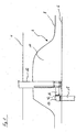
- Fig. 1 shows a submarine 2 when snorkeling below a water surface 4.
- This submarine 2 has a pressure body 6, which is surrounded by an outer skin, which forms an upper deck 8 at the top of the submarine 2.
- a tower 10 of the submarine 2 extends in the direction of the water surface 4.
- a snorkel device 12 is arranged in the form of a snorkel mast vertically extendable from the tower 10 in the direction of the water surface 4.
- Fig. 1 shows the snorkel device 12 in the extended state in which the upper, facing away from the pressure body 6 end of the snorkel mast above the water surface 4 protrudes from the water.
- a line connection is provided in the interior of the pressure body 6.
- the pressure body has an in Fig. 1 not shown, above which a housing 14 is disposed on the outside of the pressure hull.
- the housing 14 forms part of the line connection from the snorkel device 12 into the interior of the pressure hull 6, which connects one of the snorkel device 12 outgoing substantially parallel to the surface of the pressure body 6 guided line 16 with a guided from the opening of the pressure hull in the pressure body 6 line 18.
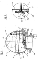
- the housing 14 serves to receive a in Fig. 2 illustrated closing body 30, with which the formed on the pressure body 6 opening for diving trips below the snorkeling depth is pressure-tight closed.
- a first pressure body side arranged housing part 20 which has a flange 22 which is fixed in the installed state on the pressure body 6 of the submarine 2.
- One of the flange 22 outgoing pipe section 24 which is provided on the pressure member 6 in the installation position facing side of the flange 22, in this case engages in the opening formed on the pressure body 6 a.
- the housing part 20 has, in the region of the flange 22, a tubular section 26, to which a section 28 adjoins the end facing away from the pressure body 6, which section widens in the shape of a shell relative to the tubular section 26.
- a closing body 30 In the region of the transition from the tubular portion 26 to the cup-shaped portion 28 of the first housing part 20 of the tubular portion 26 by means of a closing body 30 can be closed pressure-tight manner.
- the closing body 30 is designed as a cover 30, which is pivotable by means of a pivot arm formed by a connecting rod 32 into a tubular section 26 of the housing part 20 and closing this section 26 releasing position.
- Fig. 2 shows the lid 30 both in the tubular portion 26 of the housing part 20 closing position and in dash-dotted representation in the access to the section 26 releasing open position.
- the connecting rod 32 is fixed to a in the cup-shaped portion 28 of the first housing part 20 rotatably mounted actuating shaft 34.
- This actuating shaft 34 is coupled for movement with a not shown in the figures gear with a hydraulic cylinder, also not shown, wherein an extension or retraction of the hydraulic cylinder in a cover 30 in the closed or open position pivoting rotational movement of the actuating shaft 34 is transmitted.
- a flange 36 is formed, which forms a contact surface for a second housing part 38 adjoining thereto, wherein a flange 40 formed on the second housing part 38 has a contact surface and a fastening area forms with the flange 36 of the cup-shaped portion 28 of the first housing part 20.
- the second housing part 38 is designed as a substantially hemispherical hood which covers the first housing part 20 or its shell-shaped section 28. This hood is dimensioned so that the hinged to the connecting rod 32 cover 30 can be pivoted in a flow passage through the tubular portion 26 of the first housing member 26 completely releasing position.
- On the second housing part 38 is on the outside as a line connection to the line 16, which connects the housing 14 with the snorkel device 12, a normal to a central axis A of the second housing part 38 projecting pipe socket 42 is formed.
- Both the cup-shaped portion 28 of the first housing part 20 and in particular the second housing part 38 have compared to the tubular portion 26 of the first housing part 20 a significantly reduced wall thickness. This is due to the fact that the pressure-tight closable tubular portion 26 of the first housing part 20 forms part of the pressure-resistant pressure body 6 of the submarine 2 according to the invention, while the cup-shaped portion 28 of the first housing part 20 and the adjoining second housing part 36 at a tubular portion 26 of the first housing part 20 closing lid 30 for a normal dive trip, ie a dive trip below the snorkeling depth, can be flooded through the snorkel device 12 and are thus pressure balanced with respect to the environment.
- the flange 40 of the second housing part 38 has distributed over its circumference a plurality of holes 44 which are aligned perpendicular to the contact plane with the formed on the cup-shaped portion 28 of the first housing part 20 flange 36.
- the flange 36 has distributed over its circumference also a plurality of holes 46, whose arrangement corresponds to the arrangement of the holes 44 on the flange 40.
- the holes 46 formed on the flange 36 form blind holes which are provided with a thread.
- the elastic tensioning of the first housing part 20 and the second housing part 38 takes place by means of screws 48, each biasing springs 50.
- the shanks of the screws 48 are formed so long that they, when they are screwed into the holes 46 of the flange 36, protrude on the side facing away from the flange 36 of the flange 40.
- the coil springs designed as springs 50 are arranged around the screw shafts, wherein they are supported on the one hand on the heads of the screws 48 and on the other hand on the flange 40.
- the springs acting as compression springs 50 are biased so that the springs 50 press the flange 40 against the flange 36 and so press the first housing part 20 and the second housing part 38 to each other. That is, the housing parts 20 and 38 are positively connected with each other.
- the springs 50 are not pressurized with the greatest possible biasing force, Accordingly, it is possible to further compress the springs 50 starting from the prestressed state, which proves to be an advantage in a water hammer acting on the inner wall of the housing part 38.
Landscapes
- Engineering & Computer Science (AREA)
- Mechanical Engineering (AREA)
- Aviation & Aerospace Engineering (AREA)
- Radar, Positioning & Navigation (AREA)
- Pipe Accessories (AREA)
- Springs (AREA)
- Domestic Plumbing Installations (AREA)
- Crystals, And After-Treatments Of Crystals (AREA)
Applications Claiming Priority (1)
| Application Number | Priority Date | Filing Date | Title |
|---|---|---|---|
| DE102007021189A DE102007021189B3 (de) | 2007-05-05 | 2007-05-05 | Unterseeboot |
Publications (2)
| Publication Number | Publication Date |
|---|---|
| EP1990271A1 EP1990271A1 (de) | 2008-11-12 |
| EP1990271B1 true EP1990271B1 (de) | 2009-04-08 |
Family
ID=39564208
Family Applications (1)
| Application Number | Title | Priority Date | Filing Date |
|---|---|---|---|
| EP08004988A Not-in-force EP1990271B1 (de) | 2007-05-05 | 2008-03-18 | Unterseeboot |
Country Status (5)
| Country | Link |
|---|---|
| EP (1) | EP1990271B1 (ko) |
| KR (1) | KR101001334B1 (ko) |
| AT (1) | ATE427880T1 (ko) |
| DE (2) | DE102007021189B3 (ko) |
| ES (1) | ES2323198T3 (ko) |
Families Citing this family (3)
| Publication number | Priority date | Publication date | Assignee | Title |
|---|---|---|---|---|
| ITBO20110383A1 (it) * | 2011-06-29 | 2012-12-30 | Calzoni Srl | Dispositivo di aspirazione aria |
| DE102012208758B3 (de) * | 2012-05-24 | 2013-09-19 | Thyssenkrupp Marine Systems Gmbh | Verfahren zur Steuerung eines Kopfventils an einem Schnorchel eines Unterseeboots |
| KR200492163Y1 (ko) | 2015-11-11 | 2020-08-20 | 대우조선해양 주식회사 | 스노클 플랩 일체형 마스트 |
Family Cites Families (3)
| Publication number | Priority date | Publication date | Assignee | Title |
|---|---|---|---|---|
| US1099127A (en) * | 1914-02-20 | 1914-06-02 | Marley Fotheringham Hay | Ventilating-shaft for submarines. |
| US1187522A (en) * | 1915-07-28 | 1916-06-20 | Electric Boat Co | Submarine boat. |
| US6532887B1 (en) * | 2001-10-01 | 2003-03-18 | The United States Of America As Represented By The Secretary Of The Navy | Small device launch system |
-
2007
- 2007-05-05 DE DE102007021189A patent/DE102007021189B3/de not_active Expired - Fee Related
-
2008
- 2008-03-18 ES ES08004988T patent/ES2323198T3/es active Active
- 2008-03-18 DE DE502008000009T patent/DE502008000009D1/de active Active
- 2008-03-18 AT AT08004988T patent/ATE427880T1/de active
- 2008-03-18 EP EP08004988A patent/EP1990271B1/de not_active Not-in-force
- 2008-04-30 KR KR1020080040529A patent/KR101001334B1/ko not_active Expired - Fee Related
Also Published As
| Publication number | Publication date |
|---|---|
| KR101001334B1 (ko) | 2010-12-14 |
| DE502008000009D1 (de) | 2009-05-20 |
| DE102007021189B3 (de) | 2008-07-31 |
| ES2323198T3 (es) | 2009-07-08 |
| KR20080098469A (ko) | 2008-11-10 |
| EP1990271A1 (de) | 2008-11-12 |
| ATE427880T1 (de) | 2009-04-15 |
Similar Documents
| Publication | Publication Date | Title |
|---|---|---|
| EP2006201A1 (de) | Ruder für Schiffe | |
| DE202013001233U1 (de) | Hubkielvorrichtung | |
| DE2623475A1 (de) | Vorrichtung fuer die montage und demontage einer untergetauchten propellereinheit | |
| EP1990271B1 (de) | Unterseeboot | |
| DE2837420C2 (de) | Festmachevorrichtung zum Festmachen eines Schwimmkörpers an einem Anleger | |
| DE102009000991A1 (de) | In einen Bootsrumpf einsetzbares Zwischenstück | |
| EP3623276A1 (de) | Unterseeboot mit deckelöffnungsantrieb | |
| DE102010054124A1 (de) | Unterseeboot | |
| DE2005809C3 (de) | Gelenkige Leitungsablauframpe zum Führen einer von einem Wasserfahrzeug aus zu verlegenden Rohrleitung | |
| EP1935779A2 (de) | Unterseeboot | |
| EP1623920B1 (de) | Unterseeboot mit teleskopierbarem Schacht | |
| EP2365234B1 (de) | Verschlussvorrichtung | |
| DE102019203073B4 (de) | Unterseeboot mit einem Deckel mit Entlüftungsvorrichtung | |
| EP2206644A1 (de) | Unterseeboot | |
| DE10357226B3 (de) | Lagerungseinheit | |
| DE20118779U1 (de) | Ruder mit Gleitschwenkkolbenanlenkung | |
| DE3433397A1 (de) | Einrichtung zur verminderung der schwingungen von sehrohren und aehnlichen vorrichtungen | |
| DE102011089089B4 (de) | Vorrichtung zur Schalldämpfung | |
| DE3303664A1 (de) | Innenbord-aussenbordantrieb | |
| EP3892896B1 (de) | Absperrschieber, gestänge für einen absperrschieber und verfahren zum entlüften eines absperrschiebers | |
| DE102006022162B3 (de) | Unterflurhydrant | |
| DE2606787A1 (de) | Hydraulische hubzylindereinrichtung | |
| EP2874871B1 (de) | Vorrichtung zur lagerung eines schiffsmotors auf einem motorfundament | |
| DE102019200574B4 (de) | Unterwasserfahrzeug mit einem geführten Deckel | |
| DE102004062126A1 (de) | Unbemanntes Unterwasserfahrzeug |
Legal Events
| Date | Code | Title | Description |
|---|---|---|---|
| PUAI | Public reference made under article 153(3) epc to a published international application that has entered the european phase |
Free format text: ORIGINAL CODE: 0009012 |
|
| 17P | Request for examination filed |
Effective date: 20080827 |
|
| AK | Designated contracting states |
Kind code of ref document: A1 Designated state(s): AT BE BG CH CY CZ DE DK EE ES FI FR GB GR HR HU IE IS IT LI LT LU LV MC MT NL NO PL PT RO SE SI SK TR |
|
| AX | Request for extension of the european patent |
Extension state: AL BA MK RS |
|
| GRAP | Despatch of communication of intention to grant a patent |
Free format text: ORIGINAL CODE: EPIDOSNIGR1 |
|
| GRAS | Grant fee paid |
Free format text: ORIGINAL CODE: EPIDOSNIGR3 |
|
| GRAA | (expected) grant |
Free format text: ORIGINAL CODE: 0009210 |
|
| AK | Designated contracting states |
Kind code of ref document: B1 Designated state(s): AT BE BG CH CY CZ DE DK EE ES FI FR GB GR HR HU IE IS IT LI LT LU LV MC MT NL NO PL PT RO SE SI SK TR |
|
| REG | Reference to a national code |
Ref country code: GB Ref legal event code: FG4D Free format text: NOT ENGLISH |
|
| REG | Reference to a national code |
Ref country code: CH Ref legal event code: EP |
|
| REG | Reference to a national code |
Ref country code: IE Ref legal event code: FG4D |
|
| REF | Corresponds to: |
Ref document number: 502008000009 Country of ref document: DE Date of ref document: 20090520 Kind code of ref document: P |
|
| REG | Reference to a national code |
Ref country code: ES Ref legal event code: FG2A Ref document number: 2323198 Country of ref document: ES Kind code of ref document: T3 |
|
| AKX | Designation fees paid |
Designated state(s): AT BE BG CH CY CZ DE DK EE ES FI FR GB GR HR HU IE IS IT LI LT LU LV MC MT NL NO PL PT RO SE SI SK TR |
|
| PG25 | Lapsed in a contracting state [announced via postgrant information from national office to epo] |
Ref country code: SI Free format text: LAPSE BECAUSE OF FAILURE TO SUBMIT A TRANSLATION OF THE DESCRIPTION OR TO PAY THE FEE WITHIN THE PRESCRIBED TIME-LIMIT Effective date: 20090408 |
|
| REG | Reference to a national code |
Ref country code: SE Ref legal event code: TRGR |
|
| REG | Reference to a national code |
Ref country code: GR Ref legal event code: EP Ref document number: 20090401680 Country of ref document: GR |
|
| NLV1 | Nl: lapsed or annulled due to failure to fulfill the requirements of art. 29p and 29m of the patents act | ||
| REG | Reference to a national code |
Ref country code: IE Ref legal event code: FD4D |
|
| PG25 | Lapsed in a contracting state [announced via postgrant information from national office to epo] |
Ref country code: NO Free format text: LAPSE BECAUSE OF FAILURE TO SUBMIT A TRANSLATION OF THE DESCRIPTION OR TO PAY THE FEE WITHIN THE PRESCRIBED TIME-LIMIT Effective date: 20090708 Ref country code: FI Free format text: LAPSE BECAUSE OF FAILURE TO SUBMIT A TRANSLATION OF THE DESCRIPTION OR TO PAY THE FEE WITHIN THE PRESCRIBED TIME-LIMIT Effective date: 20090408 Ref country code: LT Free format text: LAPSE BECAUSE OF FAILURE TO SUBMIT A TRANSLATION OF THE DESCRIPTION OR TO PAY THE FEE WITHIN THE PRESCRIBED TIME-LIMIT Effective date: 20090408 |
|
| PG25 | Lapsed in a contracting state [announced via postgrant information from national office to epo] |
Ref country code: PL Free format text: LAPSE BECAUSE OF FAILURE TO SUBMIT A TRANSLATION OF THE DESCRIPTION OR TO PAY THE FEE WITHIN THE PRESCRIBED TIME-LIMIT Effective date: 20090408 Ref country code: LV Free format text: LAPSE BECAUSE OF FAILURE TO SUBMIT A TRANSLATION OF THE DESCRIPTION OR TO PAY THE FEE WITHIN THE PRESCRIBED TIME-LIMIT Effective date: 20090408 Ref country code: IS Free format text: LAPSE BECAUSE OF FAILURE TO SUBMIT A TRANSLATION OF THE DESCRIPTION OR TO PAY THE FEE WITHIN THE PRESCRIBED TIME-LIMIT Effective date: 20090808 Ref country code: NL Free format text: LAPSE BECAUSE OF FAILURE TO SUBMIT A TRANSLATION OF THE DESCRIPTION OR TO PAY THE FEE WITHIN THE PRESCRIBED TIME-LIMIT Effective date: 20090408 |
|
| PG25 | Lapsed in a contracting state [announced via postgrant information from national office to epo] |
Ref country code: IE Free format text: LAPSE BECAUSE OF FAILURE TO SUBMIT A TRANSLATION OF THE DESCRIPTION OR TO PAY THE FEE WITHIN THE PRESCRIBED TIME-LIMIT Effective date: 20090408 Ref country code: EE Free format text: LAPSE BECAUSE OF FAILURE TO SUBMIT A TRANSLATION OF THE DESCRIPTION OR TO PAY THE FEE WITHIN THE PRESCRIBED TIME-LIMIT Effective date: 20090408 Ref country code: DK Free format text: LAPSE BECAUSE OF FAILURE TO SUBMIT A TRANSLATION OF THE DESCRIPTION OR TO PAY THE FEE WITHIN THE PRESCRIBED TIME-LIMIT Effective date: 20090408 Ref country code: RO Free format text: LAPSE BECAUSE OF FAILURE TO SUBMIT A TRANSLATION OF THE DESCRIPTION OR TO PAY THE FEE WITHIN THE PRESCRIBED TIME-LIMIT Effective date: 20090408 Ref country code: CZ Free format text: LAPSE BECAUSE OF FAILURE TO SUBMIT A TRANSLATION OF THE DESCRIPTION OR TO PAY THE FEE WITHIN THE PRESCRIBED TIME-LIMIT Effective date: 20090408 |
|
| PLBE | No opposition filed within time limit |
Free format text: ORIGINAL CODE: 0009261 |
|
| STAA | Information on the status of an ep patent application or granted ep patent |
Free format text: STATUS: NO OPPOSITION FILED WITHIN TIME LIMIT |
|
| PG25 | Lapsed in a contracting state [announced via postgrant information from national office to epo] |
Ref country code: SK Free format text: LAPSE BECAUSE OF FAILURE TO SUBMIT A TRANSLATION OF THE DESCRIPTION OR TO PAY THE FEE WITHIN THE PRESCRIBED TIME-LIMIT Effective date: 20090408 Ref country code: HR Free format text: LAPSE BECAUSE OF FAILURE TO SUBMIT A TRANSLATION OF THE DESCRIPTION OR TO PAY THE FEE WITHIN THE PRESCRIBED TIME-LIMIT Effective date: 20090408 |
|
| 26N | No opposition filed |
Effective date: 20100111 |
|
| PG25 | Lapsed in a contracting state [announced via postgrant information from national office to epo] |
Ref country code: BG Free format text: LAPSE BECAUSE OF FAILURE TO SUBMIT A TRANSLATION OF THE DESCRIPTION OR TO PAY THE FEE WITHIN THE PRESCRIBED TIME-LIMIT Effective date: 20090708 |
|
| BERE | Be: lapsed |
Owner name: HOWALDTSWERKE-DEUTSCHE WERFT G.M.B.H. Effective date: 20100331 |
|
| PG25 | Lapsed in a contracting state [announced via postgrant information from national office to epo] |
Ref country code: MC Free format text: LAPSE BECAUSE OF NON-PAYMENT OF DUE FEES Effective date: 20100331 |
|
| PG25 | Lapsed in a contracting state [announced via postgrant information from national office to epo] |
Ref country code: BE Free format text: LAPSE BECAUSE OF NON-PAYMENT OF DUE FEES Effective date: 20100331 |
|
| PG25 | Lapsed in a contracting state [announced via postgrant information from national office to epo] |
Ref country code: MT Free format text: LAPSE BECAUSE OF FAILURE TO SUBMIT A TRANSLATION OF THE DESCRIPTION OR TO PAY THE FEE WITHIN THE PRESCRIBED TIME-LIMIT Effective date: 20090408 |
|
| PG25 | Lapsed in a contracting state [announced via postgrant information from national office to epo] |
Ref country code: CY Free format text: LAPSE BECAUSE OF FAILURE TO SUBMIT A TRANSLATION OF THE DESCRIPTION OR TO PAY THE FEE WITHIN THE PRESCRIBED TIME-LIMIT Effective date: 20090408 |
|
| PG25 | Lapsed in a contracting state [announced via postgrant information from national office to epo] |
Ref country code: HU Free format text: LAPSE BECAUSE OF FAILURE TO SUBMIT A TRANSLATION OF THE DESCRIPTION OR TO PAY THE FEE WITHIN THE PRESCRIBED TIME-LIMIT Effective date: 20091009 Ref country code: PT Free format text: LAPSE BECAUSE OF FAILURE TO SUBMIT A TRANSLATION OF THE DESCRIPTION OR TO PAY THE FEE WITHIN THE PRESCRIBED TIME-LIMIT Effective date: 20090908 Ref country code: LU Free format text: LAPSE BECAUSE OF NON-PAYMENT OF DUE FEES Effective date: 20100318 |
|
| PG25 | Lapsed in a contracting state [announced via postgrant information from national office to epo] |
Ref country code: TR Free format text: LAPSE BECAUSE OF FAILURE TO SUBMIT A TRANSLATION OF THE DESCRIPTION OR TO PAY THE FEE WITHIN THE PRESCRIBED TIME-LIMIT Effective date: 20090408 |
|
| REG | Reference to a national code |
Ref country code: CH Ref legal event code: PL |
|
| PG25 | Lapsed in a contracting state [announced via postgrant information from national office to epo] |
Ref country code: LI Free format text: LAPSE BECAUSE OF NON-PAYMENT OF DUE FEES Effective date: 20120331 Ref country code: CH Free format text: LAPSE BECAUSE OF NON-PAYMENT OF DUE FEES Effective date: 20120331 |
|
| REG | Reference to a national code |
Ref country code: DE Ref legal event code: R082 Ref document number: 502008000009 Country of ref document: DE Representative=s name: PATENTANWAELTE VOLLMANN & HEMMER, DE |
|
| REG | Reference to a national code |
Ref country code: DE Ref legal event code: R082 Ref document number: 502008000009 Country of ref document: DE Representative=s name: PATENTANWAELTE VOLLMANN & HEMMER, DE Effective date: 20130206 Ref country code: DE Ref legal event code: R082 Ref document number: 502008000009 Country of ref document: DE Effective date: 20130206 Ref country code: DE Ref legal event code: R081 Ref document number: 502008000009 Country of ref document: DE Owner name: THYSSENKRUPP MARINE SYSTEMS GMBH, DE Free format text: FORMER OWNER: HOWALDTSWERKE-DEUTSCHE WERFT GMBH, 24143 KIEL, DE Effective date: 20130206 |
|
| REG | Reference to a national code |
Ref country code: FR Ref legal event code: CD Owner name: THYSSENKRUPP MARINE SYSTEMS GMBH Effective date: 20130313 |
|
| REG | Reference to a national code |
Ref country code: ES Ref legal event code: PC2A Owner name: THYSSENKRUPP MARINE SYSTEMS GMBH Effective date: 20130912 |
|
| REG | Reference to a national code |
Ref country code: AT Ref legal event code: MM01 Ref document number: 427880 Country of ref document: AT Kind code of ref document: T Effective date: 20130318 |
|
| PG25 | Lapsed in a contracting state [announced via postgrant information from national office to epo] |
Ref country code: AT Free format text: LAPSE BECAUSE OF NON-PAYMENT OF DUE FEES Effective date: 20130318 |
|
| REG | Reference to a national code |
Ref country code: DE Ref legal event code: R084 Ref document number: 502008000009 Country of ref document: DE |
|
| REG | Reference to a national code |
Ref country code: DE Ref legal event code: R084 Ref document number: 502008000009 Country of ref document: DE Effective date: 20150206 |
|
| REG | Reference to a national code |
Ref country code: DE Ref legal event code: R082 Ref document number: 502008000009 Country of ref document: DE |
|
| REG | Reference to a national code |
Ref country code: FR Ref legal event code: PLFP Year of fee payment: 9 |
|
| REG | Reference to a national code |
Ref country code: FR Ref legal event code: PLFP Year of fee payment: 10 |
|
| REG | Reference to a national code |
Ref country code: FR Ref legal event code: PLFP Year of fee payment: 11 |
|
| REG | Reference to a national code |
Ref country code: DE Ref legal event code: R081 Ref document number: 502008000009 Country of ref document: DE Owner name: THYSSENKRUPP MARINE SYSTEMS GMBH, DE Free format text: FORMER OWNER: THYSSENKRUPP MARINE SYSTEMS GMBH, 24143 KIEL, DE |
|
| PGFP | Annual fee paid to national office [announced via postgrant information from national office to epo] |
Ref country code: FR Payment date: 20230327 Year of fee payment: 16 |
|
| PGFP | Annual fee paid to national office [announced via postgrant information from national office to epo] |
Ref country code: SE Payment date: 20230314 Year of fee payment: 16 Ref country code: GR Payment date: 20230327 Year of fee payment: 16 Ref country code: GB Payment date: 20230321 Year of fee payment: 16 Ref country code: DE Payment date: 20220801 Year of fee payment: 16 |
|
| PGFP | Annual fee paid to national office [announced via postgrant information from national office to epo] |
Ref country code: IT Payment date: 20230328 Year of fee payment: 16 Ref country code: ES Payment date: 20230527 Year of fee payment: 16 |
|
| REG | Reference to a national code |
Ref country code: DE Ref legal event code: R119 Ref document number: 502008000009 Country of ref document: DE |
|
| REG | Reference to a national code |
Ref country code: SE Ref legal event code: EUG |
|
| GBPC | Gb: european patent ceased through non-payment of renewal fee |
Effective date: 20240318 |
|
| PG25 | Lapsed in a contracting state [announced via postgrant information from national office to epo] |
Ref country code: DE Free format text: LAPSE BECAUSE OF NON-PAYMENT OF DUE FEES Effective date: 20241001 |
|
| PG25 | Lapsed in a contracting state [announced via postgrant information from national office to epo] |
Ref country code: GR Free format text: LAPSE BECAUSE OF NON-PAYMENT OF DUE FEES Effective date: 20241004 |
|
| PG25 | Lapsed in a contracting state [announced via postgrant information from national office to epo] |
Ref country code: GB Free format text: LAPSE BECAUSE OF NON-PAYMENT OF DUE FEES Effective date: 20240318 |
|
| PG25 | Lapsed in a contracting state [announced via postgrant information from national office to epo] |
Ref country code: FR Free format text: LAPSE BECAUSE OF NON-PAYMENT OF DUE FEES Effective date: 20240331 |
|
| PG25 | Lapsed in a contracting state [announced via postgrant information from national office to epo] |
Ref country code: GR Free format text: LAPSE BECAUSE OF NON-PAYMENT OF DUE FEES Effective date: 20241004 Ref country code: GB Free format text: LAPSE BECAUSE OF NON-PAYMENT OF DUE FEES Effective date: 20240318 Ref country code: FR Free format text: LAPSE BECAUSE OF NON-PAYMENT OF DUE FEES Effective date: 20240331 Ref country code: DE Free format text: LAPSE BECAUSE OF NON-PAYMENT OF DUE FEES Effective date: 20241001 |
|
| PG25 | Lapsed in a contracting state [announced via postgrant information from national office to epo] |
Ref country code: IT Free format text: LAPSE BECAUSE OF NON-PAYMENT OF DUE FEES Effective date: 20240318 |
|
| REG | Reference to a national code |
Ref country code: ES Ref legal event code: FD2A Effective date: 20250429 |
|
| PG25 | Lapsed in a contracting state [announced via postgrant information from national office to epo] |
Ref country code: ES Free format text: LAPSE BECAUSE OF NON-PAYMENT OF DUE FEES Effective date: 20240319 |
|
| PG25 | Lapsed in a contracting state [announced via postgrant information from national office to epo] |
Ref country code: SE Free format text: LAPSE BECAUSE OF NON-PAYMENT OF DUE FEES Effective date: 20240319 |