EP1989062B1 - Pneumatique pour vehicules - Google Patents
Pneumatique pour vehicules Download PDFInfo
- Publication number
- EP1989062B1 EP1989062B1 EP07726445A EP07726445A EP1989062B1 EP 1989062 B1 EP1989062 B1 EP 1989062B1 EP 07726445 A EP07726445 A EP 07726445A EP 07726445 A EP07726445 A EP 07726445A EP 1989062 B1 EP1989062 B1 EP 1989062B1
- Authority
- EP
- European Patent Office
- Prior art keywords
- reinforcing elements
- layer
- tyre
- working
- circumferential
- Prior art date
- Legal status (The legal status is an assumption and is not a legal conclusion. Google has not performed a legal analysis and makes no representation as to the accuracy of the status listed.)
- Not-in-force
Links
Images

Classifications
-
- B—PERFORMING OPERATIONS; TRANSPORTING
- B60—VEHICLES IN GENERAL
- B60C—VEHICLE TYRES; TYRE INFLATION; TYRE CHANGING; CONNECTING VALVES TO INFLATABLE ELASTIC BODIES IN GENERAL; DEVICES OR ARRANGEMENTS RELATED TO TYRES
- B60C15/00—Tyre beads, e.g. ply turn-up or overlap
- B60C15/0009—Tyre beads, e.g. ply turn-up or overlap features of the carcass terminal portion
- B60C15/0018—Tyre beads, e.g. ply turn-up or overlap features of the carcass terminal portion not folded around the bead core, e.g. floating or down ply
-
- B—PERFORMING OPERATIONS; TRANSPORTING
- B60—VEHICLES IN GENERAL
- B60C—VEHICLE TYRES; TYRE INFLATION; TYRE CHANGING; CONNECTING VALVES TO INFLATABLE ELASTIC BODIES IN GENERAL; DEVICES OR ARRANGEMENTS RELATED TO TYRES
- B60C9/00—Reinforcements or ply arrangement of pneumatic tyres
- B60C9/18—Structure or arrangement of belts or breakers, crown-reinforcing or cushioning layers
- B60C9/20—Structure or arrangement of belts or breakers, crown-reinforcing or cushioning layers built-up from rubberised plies each having all cords arranged substantially parallel
- B60C9/2003—Structure or arrangement of belts or breakers, crown-reinforcing or cushioning layers built-up from rubberised plies each having all cords arranged substantially parallel characterised by the materials of the belt cords
- B60C9/2009—Structure or arrangement of belts or breakers, crown-reinforcing or cushioning layers built-up from rubberised plies each having all cords arranged substantially parallel characterised by the materials of the belt cords comprising plies of different materials
-
- Y—GENERAL TAGGING OF NEW TECHNOLOGICAL DEVELOPMENTS; GENERAL TAGGING OF CROSS-SECTIONAL TECHNOLOGIES SPANNING OVER SEVERAL SECTIONS OF THE IPC; TECHNICAL SUBJECTS COVERED BY FORMER USPC CROSS-REFERENCE ART COLLECTIONS [XRACs] AND DIGESTS
- Y10—TECHNICAL SUBJECTS COVERED BY FORMER USPC
- Y10T—TECHNICAL SUBJECTS COVERED BY FORMER US CLASSIFICATION
- Y10T152/00—Resilient tires and wheels
- Y10T152/10—Tires, resilient
- Y10T152/10495—Pneumatic tire or inner tube
- Y10T152/10765—Characterized by belt or breaker structure
- Y10T152/1081—Breaker or belt characterized by the chemical composition or physical properties of elastomer or the like
Definitions
- the invention relates to a tire intended to equip a vehicle and more particularly intended to equip a two-wheeled vehicle such as a motorcycle.
- the reinforcing or reinforcing armature for tires and especially motorcycle tires is at present - and most often - constituted by stacking one or more plies conventionally referred to as "carcass plies", “crown plies”, etc. .
- This method of designating reinforcing reinforcements comes from the manufacturing process, consisting in producing a series of semi-finished products in the form of plies, provided with wire reinforcements, often longitudinal, which are subsequently assembled or stacked in order to make a rough draft. pneumatic.
- the sheets are made flat, with deys, large dimensions, and are subsequently cut according to the dimensions of a given product.
- the assembly of the plies is also made, initially, substantially flat.
- the blank thus produced is then shaped to adopt the typical toroidal profile of the tires.
- the so-called "finished” semi-finished products are then applied to the blank to obtain a product ready for vulcanization.
- Such a type of "conventional” method involves, in particular for the manufacturing phase of the blank of the tire, the use of an anchoring element (generally a bead wire), used to carry out the anchoring or the maintenance of the carcass reinforcement in the area of the beads of the tire.
- an anchoring element generally a bead wire
- a portion of all the plies constituting the carcass reinforcement is turned around around a bead wire disposed in the bead of the tire. In this way, an anchoring of the carcass reinforcement in the bead is created.
- the tires described in this document do not have the "traditional" reversal of carcass ply around a rod.
- This type of anchorage is replaced by an arrangement in which is disposed adjacent to said sidewall reinforcing structure circumferential son, all being embedded in a rubber mix anchoring or bonding.
- the conventional terms such as “plies”, “rods”, etc.
- the term “carcass-type reinforcement” or “sidewall reinforcement” is used to designate the reinforcement elements of a carcass ply in the conventional method, and the corresponding reinforcing elements, generally applied at the flanks, to the carcass ply. a tire produced according to a process without semi-finished.
- anchoring zone can refer to both the “traditional” reversal of carcass ply around a rod of a conventional process, that the assembly formed by the circumferential reinforcing elements, the mixture rubbery and adjacent portions of sidewall reinforcement of a low zone made with a method with application to a toroidal core.
- the longitudinal direction of the tire is the direction corresponding to the periphery of the tire and defined by the rolling direction of the tire.
- a circumferential plane or circumferential plane of section is a plane perpendicular to the axis of rotation of the tire.
- the equatorial plane is the circumferential plane passing through the center or crown of the tread.
- the transverse or axial direction of the tire is parallel to the axis of rotation of the tire.
- the radial direction is a direction intersecting the axis of rotation of the tire and perpendicular to it.
- the axis of rotation of the tire is the axis around which it rotates under normal use.
- a radial or meridian plane contains the axis of rotation of the tire.
- the architecture of such tires comprising a carcass reinforcement formed of one or two layers of elements of reinforcing making with the circumferential direction an angle which can be between 65 ° and 90 °, said carcass reinforcement being radially surmounted by a crown reinforcement formed of reinforcing elements.
- the invention also relates to partially radial tires, that is to say the reinforcing elements of the carcass reinforcement are radial on at least a portion of said carcass reinforcement, for example in the portion corresponding to the top of the tire.
- a first structure consists, for said crown reinforcement, in using only circumferential cables, and said structure is more particularly used for the career position.
- a second structure directly inspired by the structures commonly used in passenger car tires, has been used to improve the wear resistance, and consists in the use of at least two layers of working crown of reinforcing elements. substantially parallel to each other in each layer but crossed from one layer to the next making sharp angles with the circumferential direction, such tires being more particularly adapted for the front of the motorcycles.
- Said two working crown layers may be associated with at least one layer of circumferential elements, generally obtained by helically winding a strip of at least one rubber-coated reinforcing element.
- tire vertex architectures directly affects certain properties of the tires such as wear, endurance, grip or even comfort when driving or in cases including motorcycles stability.
- other tire parameters such as the nature of the rubber compounds constituting the tread also affect the properties of said tire.
- the choice and the nature of the rubber compounds constituting the tread are, for example, essential parameters relating to the wear properties.
- the choice and the nature of the mixtures rubbery constituent the tread also affect the adhesion properties of the tire.
- the aim of the invention is to provide a tire making it possible to improve the wear properties of the tire and to improve the adhesion properties of the tread of said tire, in particular during curve crossing in the case of tires for the tire. motorcycle.
- a tire comprising a carcass-type reinforcement structure, formed of reinforcement elements, anchored on each side of the tire to a bead whose base is intended to be mounted on a rim seat. , each bead extending radially outwardly by a sidewall, the flanks joining radially outwardly a tread, and having under the tread a crown reinforcement structure consisting of at least two layers of elements said working layer reinforcing elements being identical in nature, and in a given circumferential plane, the extension stiffness per unit width of a first working layer measured in the main direction of the elements reinforcing said first layer being strictly greater than the extension stiffness per unit width of a second working layer measured in the main direction of the reinforcing elements of said second working layer, the second working layer being radially further away from the carcass structure than said first working layer.
- working layers are reinforcing element layers having, at least in the central portion of the tread, angles with the circumferential direction of between 10 and 80 °.
- the central zone is a peripheral zone or band centered on the crown of the tread itself defined by the equatorial plane of the tire.
- the nature of the reinforcing elements is the material constituting them.
- the principal direction of the reinforcing elements is defined by the direction of the tangent to the reinforcing elements at the point of intersection of the reinforcing elements and the given circumferential plane.
- the width unit is defined in the sense of the invention in a direction perpendicular to the main direction of the reinforcing elements.
- the stiffness of extension of a layer of reinforcing elements is the property of said layer of reinforcing elements connecting a stress supported by said layer and the corresponding deformation of said layer.
- the production of a tire according to the invention confers superior circumferential and axial stiffnesses to the tire and therefore a better performance or better adhesion performance, especially during curve passes.
- These circumferential and upper axial stiffnesses according to the invention are a consequence of the increase in the stiffness of the working layer radially closest to the carcass structure, and therefore the most important participant. effectively to said circumferential and axial stiffnesses.
- the extension stiffness per unit width of the working layers measured along the principal direction of the reinforcing elements of said layers decreases gradually when the radial distance between the layer work and carcass structure increases.
- the extension stiffness per unit width of the third working layer measured along the principal direction of the reinforcing elements of said third layer is strictly less than the extension stiffness per unit width of the second layer of work measured in the main direction of the reinforcement elements of said second working layer, the second working layer being radially less distant from the carcass structure than said third working layer and the second working layer being radially further away from the structure a first working layer, said first working layer having an extension stiffness per unit width measured in the main direction of the reinforcing elements of said first layer strictly greater than the extension stiffness per unit width of said second measured working layer in the main direction of the reinforcing elements of said second working layer.
- the diameters of the reinforcing elements of the first working layer are larger than the diameters of the reinforcing elements of the second working layer.
- the density of reinforcing elements of the first working layer is greater than the density of reinforcement elements of the second working layer.
- the difference in stiffness between the working layers can still be obtained by a combination of the two embodiments of embodiments shown above.
- the absolute value of the angles formed with the circumferential direction by the elements of reinforcement of different working layers are different from one working layer to another.
- the tests have also shown that variations of angles of the reinforcing elements from one working layer to another may also make it possible to modify the stiffnesses of the tire.
- the reinforcement elements of a working layer have identical angles, formed with the longitudinal direction, said angles being measured at intersection points with a circumferential plane, regardless of said circumferential plane.
- the reinforcing elements all have the same angle formed with the longitudinal direction at the points of intersection with said circumferential cutting plane.
- the aforementioned angle may vary according to the circumferential section plane considered.
- the reinforcing elements are equidistant from each other in all circumferential planes; the distance separating adjacent reinforcing elements that can in turn vary according to the circumferential plane of section considered, or more precisely, the distance between adjacent reinforcing elements that can vary in the axial direction.
- the reinforcing elements of two radially adjacent working layers form between them angles between 20 and 160 °.
- An alternative embodiment of the invention provides that at least one working layer is made at least partially radially inside the carcass-type reinforcement structure.
- the set of working layers is made radially inside at least one carcass structure, that is to say within at least one carcass layer. At least one carcass-type reinforcement structure thus radially covers the complete crown reinforcement structure.
- At least one layer of work reinforcing elements of the reinforcement structure of vertex is made radially outside the carcass-type reinforcement structure.
- the layer of work reinforcing elements assumes a protective function with respect to the carcass and the other layers of the crown reinforcement structure, against possible mechanical aggression.
- a layer of work reinforcing elements can be made in several parts placed in different radial positions or different levels of the tire.
- Such a tire may in particular comprise a part of the layer of reinforcing elements working radially outside the reinforcing elements of the carcass structure in the central part of the tire, that is to say under the central part. of the tread.
- This part of the layer of work reinforcing elements then allows in particular a protection of the carcass against possible attacks that may occur through the central portion of the tread, considered the most exposed.
- the invention further provides, in the case of a layer of work reinforcement elements made in several parts placed in different radial positions, that the distribution of these different parts is not carried out symmetrically with respect to the plane equatorial, or circumferential plane passing through the center of the crown of the tire.
- the invention advantageously provides an overlap of the axial ends of said parts together.
- a tire according to the invention in particular when at least a part of the crown reinforcement structure is produced radially inside the carcass structure, is advantageously produced according to a manufacturing technique of the hard core or rigid form type. .
- At least one layer of work-reinforcing elements consists of at least one continuous reinforcing wire forming in the central zone of said layer sections having angles, formed with the longitudinal direction, identical, said angles being measured at the points of intersection with a circumferential plane, two adjacent sections being connected by a loop, and the sections forming an angle with the longitudinal direction of between 10 and 80 °.
- wire generally refers to both mono-filaments, multifilamentary fibers (possibly twisted on themselves) or assemblies such as textile or metal cords, twists or any type of equivalent assembly, such as for example a hybrid cable, and this, whatever the material or materials, the possible treatment of these son, for example a surface treatment or coating, or pre-gluing, to promote adhesion to the rubber or any other matter.
- the working layer is made with at least one wire of which no free end is present on the edges of said layer.
- the embodiment of the layer is made with a single wire and the layer is of the "single-wire" type.
- the industrial production of such layers leads to discontinuities, in particular due to coil changes.
- a preferred embodiment of the invention is still to use only one or a small number of son for a working layer and it is appropriate to have the beginnings and ends of son in the central zone of said layer.
- a tire according to the invention thus produced comprises a reinforcing structure which has no free end of the reinforcing elements at the axially outer edges of the working layers.
- Such a tire is advantageously made according to a technique of the type on hard or toroidal core which allows in particular the establishment of reinforcement elements in the near-final position; indeed, a conformation step is not required according to this type of method the reinforcing elements are no longer moved after their introduction.
- the angles formed by said sections of the thread of the working layers with the longitudinal direction are variable in the transverse direction such that said angles are greater on the axially outer edges of the reinforcing element layers with respect to the angles of said sections measured at the equatorial plane of the tire.
- a technique of the hard core type in particular allows simple variations of angles much greater than what is possible to obtain according to methods comprising a conformation step.
- said angle variations said angle tending to 90 ° to the edges of the working layers, leads to an increase in pitch and promotes the production of loops, because of the reduction in size.
- a first embodiment of the embodiments of the invention according to which the angles formed by said sections of the wire of the working layers with the longitudinal direction are variable in the transverse direction, consists in varying the angle of the sections of a monotonically from the equatorial plane of the tire to the edges of the working layer.
- a second embodiment of these variants is to change the angle stepwise from the equatorial plane of the tire to the edges of the working layer.
- a final embodiment of these variants consists of an evolution of the angle such that given values are obtained for given axial positions.
- angles formed by said sections of the wire of the working layers with the longitudinal direction are variable in the transverse direction allow in other words, to obtain a high rigidity circumferentially of the crown reinforcement structure by the presence of closed, i.e., small, angles in the area of the tire crown, i.e. in the area surrounding the equatorial plane.
- closed angles that is to say angles tending towards 45 °, see beyond 90 °, can be obtained on the edges of the working layer or more precisely at the level of tire shoulders to improve the grip, traction, comfort, or the operating temperature of the tire; in fact, such angle variations make it possible to modulate the shear stiffnesses of the working layers.
- the reinforcing elements of the working layers are made of textile material.
- the reinforcement elements of the working layers are made of metal.
- the tire comprises in particular a crown reinforcement structure which further comprises at least one layer of circumferential reinforcing elements; according to the invention, the layer of circumferential reinforcing elements consists of at least one reinforcing element oriented at an angle formed with the longitudinal direction less than 5 °.
- a layer of circumferential reinforcing elements is particularly preferable for the production of a tire intended to be used in the rear of a motorcycle.
- An advantageous embodiment of the invention provides that the layer of circumferential reinforcing elements is positioned at least partially on a working layer.
- the layer of circumferential reinforcing elements is made on two working layers and placed directly under the tread, it can notably contribute to the improvement of stability at high speed.
- the layer of circumferential reinforcing elements can thus be made directly under the tread to form, in addition to its primary function, a protective layer of the carcass and the other layers of the crown reinforcement structure, against possible mechanical aggression.
- the layer of circumferential reinforcing elements can also be produced between the working layers, in particular for economic reasons, the quantity of material and the exposure time thus being reduced.
- the layer of circumferential reinforcing elements is positioned at least partially radially within the radially innermost working layer.
- the layer of circumferential reinforcing elements is made radially inside the working layers and may in particular improve the adhesion and traction of the tire.
- Another variant of the invention provides that at least one layer of circumferential reinforcing elements is positioned at least partially radially inside the carcass-type reinforcement structure.
- This variant embodiment can also take over the different positions mentioned above with respect to the working layers.
- the carcass can thus cover the complete crown reinforcement structure.
- the invention provides that at least one crown reinforcement layer is placed between the carcass and the tread to provide protection of the carcass.
- a tire according to the invention in particular when at least a portion of the crown reinforcement structure is made radially inside the carcass structure, is advantageously produced according to a technique manufacturing type hard core or rigid form.
- the reinforcing elements of the layer of circumferential reinforcing elements are metallic and / or textile and / or glass.
- the invention provides in particular the use of reinforcing elements of different types in the same layer of circumferential reinforcing elements.
- the reinforcing elements of the layer of circumferential reinforcing elements have a modulus of elasticity greater than 6000 N / mm 2 .
- a layer of circumferential reinforcing elements may be made in several parts placed in different radial positions or different levels of the tire.
- Such a tire may in particular comprise a part of the layer of circumferential reinforcing elements radially outside the other reinforcing elements in the central part of the tire, that is to say under the central part of the tread. .
- This part of the layer of circumferential reinforcing elements then makes it possible, in particular, to protect the carcass against possible attacks that may occur by the central part of the tread, considered to be the most important exposed.
- Lateral portions of the layer of circumferential reinforcing elements can be positioned at all levels, that is to say either radially inside the layers. working either between them or still radially inside the carcass layer, in particular to reduce the amount of reinforcing elements and the time of production of such a layer of circumferential reinforcing elements.
- the invention further provides, in the case of a layer of circumferential reinforcing elements made in several parts placed in different radial positions, that the distribution of these different parts is not carried out symmetrically with respect to the equatorial plane. , or circumferential plane passing through the center of the crown of the tire. Such a non-symmetrical distribution may also be linked to a choice of materials different from the circumferential reinforcing elements.
- the invention advantageously provides an overlap of the axial ends of said parts together.
- An alternative embodiment of the invention advantageously provides that the circumferential reinforcing elements are distributed in the transverse direction with a variable pitch.
- said pitch at the center (top) of the tread is less important than at the edges of said layer.
- Such an embodiment according to the invention particularly promotes resistance to external aggressions which are greater in the central area of the tire.
- said pitch at the center (top) of the tread is greater than at the edges of said layer.
- the value of the pitch in the transverse direction obeys a sequence over at least a portion of the axial width of said layer going to the edges of said layer.
- the pitch between the circumferential reinforcing elements of said layer is advantageously constant in an area covering the crown of the tread.
- the value of the pitch may be a combination of several sequences as a function of the axial position on said layer.
- the variation of the pitch between the circumferential reinforcing elements results in a variation in the number of circumferential reinforcing elements per unit length in the transverse direction and consequently in a variation of the density of circumferential reinforcing elements in the transverse direction and therefore by a variation of the circumferential rigidity in the transverse direction.
- the reinforcing elements of the reinforcing structure, of the carcass type form with the circumferential direction an angle of between 65 ° and 90 °.
- an advantageous embodiment of the invention further provides that the carcass-type reinforcement structure consists of two half-plies extending for example from the shoulders to the beads.
- the invention effectively provides for the removal of the carcass structure in at least a portion of the tire area under the tread.
- the realization of such a carcass structure can be made according to the teaching of the document EP-A-0 844 106 . Relative positions previously stated different layers of the crown reinforcement structure are also compatible with such a carcass structure.
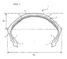
- the figure 1 represents a tire 1 comprising a carcass reinforcement consisting of a single layer 2 comprising textile-type reinforcing elements.
- the layer 2 consists of reinforcing elements arranged radially.
- the radial positioning of the reinforcing elements is defined by the angle of application of said reinforcing elements; a radial arrangement corresponds to an angle of application of said elements with respect to the longitudinal direction of the tire of between 65 ° and 90 °.
- Said carcass layer 2 is anchored on each side of the tire 1 in a bead 3 whose base is intended to be mounted on a rim seat.
- Each bead 3 is extended radially outwardly by a sidewall 4, said sidewall 4 radially outwardly joining the tread 5.
- the tire 1 thus formed has a curvature value greater than 0.15 and preferably greater than 0.3.
- the curvature value is defined by the ratio Ht / Wt, that is to say by the ratio of the height of the tread on the maximum width of the tread of the tire.
- the value of curvature will advantageously be between 0.25 and 0.5 for a tire intended to be mounted at the front of a motorcycle and it will advantageously be between 0.2 and 0.5 for a tire intended to be mounted at the rear.
- the tire 1 further comprises a crown reinforcement 6 consisting of two layers 7 and 8 of reinforcing elements making angles with the circumferential direction; said reinforcing elements being crossed from one layer to the next by making between them angles equal to 50 ° in the region of the equatorial plane, the reinforcing elements of each of the layers 7 and 8 forming an angle equal to 25 ° with the circumferential direction.
- a crown reinforcement 6 consisting of two layers 7 and 8 of reinforcing elements making angles with the circumferential direction; said reinforcing elements being crossed from one layer to the next by making between them angles equal to 50 ° in the region of the equatorial plane, the reinforcing elements of each of the layers 7 and 8 forming an angle equal to 25 ° with the circumferential direction.
- the reinforcing elements of the two layers 7 and 8 are made of textile material and more precisely aramid.
- the density of reinforcing elements in the radially innermost layer 7 is equal to 95 threads / dm (threads per decimeter).
- the density of reinforcement elements in the radially outermost layer 8 is equal to 45 threads / dm.
- the density of reinforcing elements of the radially innermost layer 7 is greater than the density of reinforcement elements of the radially outermost layer 8.
- Tests have been carried out with such a 120 / 70R17 tire and compared with those made with a standard tire of the same dimension consisting of a similar architecture, the two working layers having reinforcing element densities identical to and equal to 70 threads / dm and reinforcing elements having identical angles to those of the tire according to the invention.
- the standard tire used for the comparison thus has an overall stiffness, defined in particular by the sum of the densities of reinforcement elements of the working layers, identical to that of the tire according to the invention.
- the second type of testing is quantitative. It consisted in determining the distance traveled by each of the tires on test machines simulating a running in a straight line with an imposed load.
- the tire according to the invention has a gain in distance traveled of the order of 4% compared to the distance traveled by the standard reference tire.
- FIG. 2 On the figure 2 , is shown a tire 21 similar to that of the figure 1 and which differs in the presence of a layer of circumferential reinforcing elements 29 radially outside the layers 27, 28 of the crown reinforcement 26.
- the layer of circumferential reinforcing elements 29 is thus the part of the radially outer crown reinforcement and the two working layers 27, 28 are interposed between the carcass layer 22 and the layer of circumferential reinforcing elements 29.
- the layer of circumferential reinforcing elements is advantageously constituted of a single wire wound to form an angle with the longitudinal direction substantially equal to 0 °.
- the layer of circumferential reinforcing elements can be further achieved by the simultaneous winding of several bare wires or in the form of strips when embedded in rubber.
- the working layers 27, 28 consist of textile reinforcements and are made according to the invention, the density of reinforcement elements of the radially innermost layer 27 being greater than the density of reinforcing elements of the invention. the layer 28.
- the invention should of course not be interpreted in a limiting manner in view of these two exemplary embodiments.
- the variation in stiffness of extension per unit width of a working layer measured in the main direction of the reinforcing elements of said layer can also be obtained by example by differences in diameter of the reinforcing elements or even by a combination of different means.
- the invention also extends to tires which may comprise more complex crown reinforcements comprising, for example, three or more working layers of reinforcement elements forming an angle with the circumferential direction.
- the invention also applies to the various cases of vertex reinforcement previously described and in particular described in the patent applications WO 2004/018236 , WO 2004/018237 , WO 2005/070704 , WO 2005/070706 , in particular having the different radial positions of the layers constituting the crown reinforcement with respect to each other, as well as their radial position with respect to the carcass structure, as well as the constitution of a layer formed by a wire constituting sections connected by loops or the variation of the angles of said sections in the axial direction.
Landscapes
- Engineering & Computer Science (AREA)
- Mechanical Engineering (AREA)
- Tires In General (AREA)
- Pulleys (AREA)
- Turning (AREA)
- Control Of Driving Devices And Active Controlling Of Vehicle (AREA)
- Transition And Organic Metals Composition Catalysts For Addition Polymerization (AREA)
Applications Claiming Priority (2)
| Application Number | Priority Date | Filing Date | Title |
|---|---|---|---|
| FR0601575A FR2897557B1 (fr) | 2006-02-21 | 2006-02-21 | Pneumatique pour vehicules |
| PCT/EP2007/051624 WO2007096360A1 (fr) | 2006-02-21 | 2007-02-20 | Pneumatique pour vehicules |
Publications (2)
| Publication Number | Publication Date |
|---|---|
| EP1989062A1 EP1989062A1 (fr) | 2008-11-12 |
| EP1989062B1 true EP1989062B1 (fr) | 2010-10-27 |
Family
ID=37074683
Family Applications (1)
| Application Number | Title | Priority Date | Filing Date |
|---|---|---|---|
| EP07726445A Not-in-force EP1989062B1 (fr) | 2006-02-21 | 2007-02-20 | Pneumatique pour vehicules |
Country Status (9)
| Country | Link |
|---|---|
| US (1) | US8499808B2 (cg-RX-API-DMAC7.html) |
| EP (1) | EP1989062B1 (cg-RX-API-DMAC7.html) |
| JP (1) | JP5238515B2 (cg-RX-API-DMAC7.html) |
| CN (1) | CN101384440B (cg-RX-API-DMAC7.html) |
| AT (1) | ATE485952T1 (cg-RX-API-DMAC7.html) |
| DE (1) | DE602007010104D1 (cg-RX-API-DMAC7.html) |
| ES (1) | ES2355303T3 (cg-RX-API-DMAC7.html) |
| FR (1) | FR2897557B1 (cg-RX-API-DMAC7.html) |
| WO (1) | WO2007096360A1 (cg-RX-API-DMAC7.html) |
Families Citing this family (2)
| Publication number | Priority date | Publication date | Assignee | Title |
|---|---|---|---|---|
| DE102012104819A1 (de) | 2012-06-04 | 2013-12-05 | Continental Reifen Deutschland Gmbh | Fahrzeugluftreifen |
| JP2023148526A (ja) * | 2022-03-30 | 2023-10-13 | 住友ゴム工業株式会社 | 二輪自動車用タイヤ対 |
Family Cites Families (22)
| Publication number | Priority date | Publication date | Assignee | Title |
|---|---|---|---|---|
| FR1538478A (fr) * | 1967-07-24 | 1968-09-06 | Uniroyal Englebert France | Enveloppe de pneumatique à carcasse radiale à flancs renforcés |
| JPS57100502U (cg-RX-API-DMAC7.html) * | 1981-11-24 | 1982-06-21 | ||
| US5435370A (en) * | 1985-05-08 | 1995-07-25 | Uniroyal Goodrich Licensing Services, Inc. | Pneumatic tire having discontinuous outer carcass ply |
| JPH01109106A (ja) * | 1987-10-23 | 1989-04-26 | Bridgestone Corp | 二輪車用空気入りラジアルタイヤ |
| JPH06328592A (ja) * | 1993-05-26 | 1994-11-29 | Bridgestone Corp | 空気入りタイヤの製造方法 |
| JP3556712B2 (ja) * | 1994-09-19 | 2004-08-25 | 株式会社ブリヂストン | 空気入りタイヤ |
| US5662751A (en) * | 1994-09-20 | 1997-09-02 | Michelin Recherche Et Technique S.A. | Tire with a specified two-ply steel-aramid belt package |
| JPH08156513A (ja) * | 1994-12-09 | 1996-06-18 | Bridgestone Corp | 空気入りラジアルタイヤ |
| IT1277400B1 (it) * | 1995-08-01 | 1997-11-10 | Pirelli | Pneumatico ad elevata curvatura trasversale particolarmente per veicolo a due ruote |
| GB9603948D0 (en) * | 1996-02-24 | 1996-04-24 | Sumitomo Rubber Ind | Reinforcement ply and method of manufacture |
| IT1283051B1 (it) * | 1996-05-22 | 1998-04-07 | Pirelli | Coppia di pneumatici ad elevata curvatura trasversale,particolarmente per veicoli a due ruote e metodo per il controllo del comportamento |
| FR2754769B1 (fr) * | 1996-10-23 | 1998-12-11 | Michelin & Cie | Armature de sommet pour pneumatique "poids-lourds" de rapport de forme < 0,60 |
| FR2755904A1 (fr) * | 1996-11-21 | 1998-05-22 | Michelin & Cie | Renforcement de carcasse pour pneumatique, realise a partir d'un fil unique |
| JP4112079B2 (ja) * | 1997-07-09 | 2008-07-02 | 株式会社ブリヂストン | 空気入りラジアルタイヤ |
| BR9917588A (pt) * | 1999-12-21 | 2002-08-06 | Goodyear Tire & Rubber | Pacote de reforço para pneumáticos |
| US6668889B1 (en) * | 1999-12-21 | 2003-12-30 | The Goodyear Tire & Rubber Company | Reinforcement package for tires |
| FR2810924B1 (fr) * | 2000-07-03 | 2003-04-11 | Michelin Soc Tech | Pneumatique avec des bourrelets de structure amelioree |
| EP1307350B1 (fr) * | 2000-07-31 | 2005-01-26 | Société de Technologie Michelin | Pneumatique pour vehicule deux roues comportant un moyen anti-vibration |
| US7404425B2 (en) * | 2002-04-24 | 2008-07-29 | The Goodyear Tire & Rubber Company | Belt package for super single truck tires |
| JP4522858B2 (ja) * | 2002-08-09 | 2010-08-11 | ソシエテ ド テクノロジー ミシュラン | 二輪付き車両用のタイヤ |
| US7658216B2 (en) * | 2002-08-09 | 2010-02-09 | Michelin Recherche Et Technique S.A. | Tire for two-wheeled vehicle comprising looped crown reinforcement |
| JP4558733B2 (ja) * | 2004-07-16 | 2010-10-06 | 株式会社ブリヂストン | 二輪自動車用タイヤ |
-
2006
- 2006-02-21 FR FR0601575A patent/FR2897557B1/fr not_active Expired - Fee Related
-
2007
- 2007-02-20 DE DE602007010104T patent/DE602007010104D1/de active Active
- 2007-02-20 ES ES07726445T patent/ES2355303T3/es active Active
- 2007-02-20 EP EP07726445A patent/EP1989062B1/fr not_active Not-in-force
- 2007-02-20 AT AT07726445T patent/ATE485952T1/de not_active IP Right Cessation
- 2007-02-20 US US12/279,586 patent/US8499808B2/en not_active Expired - Fee Related
- 2007-02-20 WO PCT/EP2007/051624 patent/WO2007096360A1/fr not_active Ceased
- 2007-02-20 CN CN200780005974.7A patent/CN101384440B/zh not_active Expired - Fee Related
- 2007-02-20 JP JP2008555780A patent/JP5238515B2/ja not_active Expired - Fee Related
Also Published As
| Publication number | Publication date |
|---|---|
| US8499808B2 (en) | 2013-08-06 |
| DE602007010104D1 (de) | 2010-12-09 |
| FR2897557B1 (fr) | 2008-04-18 |
| JP5238515B2 (ja) | 2013-07-17 |
| CN101384440B (zh) | 2013-09-25 |
| EP1989062A1 (fr) | 2008-11-12 |
| ATE485952T1 (de) | 2010-11-15 |
| JP2009527414A (ja) | 2009-07-30 |
| ES2355303T3 (es) | 2011-03-24 |
| CN101384440A (zh) | 2009-03-11 |
| FR2897557A1 (fr) | 2007-08-24 |
| WO2007096360A1 (fr) | 2007-08-30 |
| US20090218025A1 (en) | 2009-09-03 |
Similar Documents
| Publication | Publication Date | Title |
|---|---|---|
| EP2379348B1 (fr) | Pneumatique pour vehicules comportant une couche d'elements de renforcement circonferentiels | |
| EP2379343B1 (fr) | Pneumatique pour vehicules a carcasse interrompue et comportant une couche d'elements de renforcement circonferentiels | |
| EP2234819B1 (fr) | Pneumatique allege comportant une structure de carcasse non radiale | |
| EP1545909B1 (fr) | Pneumatique pour deux roues | |
| EP2379344B1 (fr) | Pneumatique pour vehicules comportant une bande de roulement constituee de plusieurs melanges et une couche d'elements de renforcement circonferentiels a pas variable | |
| EP1545910B1 (fr) | Pneumatique pour deux roues | |
| EP2237975B1 (fr) | Pneumatique radial allege | |
| EP2237974B1 (fr) | Pneumatique allege | |
| EP1699646B1 (fr) | Pneumatique pour vehicules | |
| EP2379342B1 (fr) | Pneumatique pour vehicules comportant une armature de carcasse interrompue et une bande de roulement constituee de plusieurs melanges | |
| EP2331350B1 (fr) | Pneumatique pour vehicules lourds comportant au moins dans chaque epaule au moins deux couches additionnelles dans l'armature de sommet | |
| EP1989062B1 (fr) | Pneumatique pour vehicules | |
| EP1699645B1 (fr) | Pneumatique pour vehicules | |
| EP2234820B1 (fr) | Pneumatique allege comportant une couche de sommet radialement interieure a la structure de carcasse | |
| EP2219886B1 (fr) | Vehicule dont les pneumatiques comportent des flancs renforces | |
| FR2915131A1 (fr) | Pneumatique pour vehicule comportant des renforts dans les flancs | |
| EP1883545B1 (fr) | Pneumatiques pour deux roues |
Legal Events
| Date | Code | Title | Description |
|---|---|---|---|
| PUAI | Public reference made under article 153(3) epc to a published international application that has entered the european phase |
Free format text: ORIGINAL CODE: 0009012 |
|
| 17P | Request for examination filed |
Effective date: 20080922 |
|
| AK | Designated contracting states |
Kind code of ref document: A1 Designated state(s): AT BE BG CH CY CZ DE DK EE ES FI FR GB GR HU IE IS IT LI LT LU LV MC NL PL PT RO SE SI SK TR |
|
| 17Q | First examination report despatched |
Effective date: 20090417 |
|
| GRAP | Despatch of communication of intention to grant a patent |
Free format text: ORIGINAL CODE: EPIDOSNIGR1 |
|
| DAX | Request for extension of the european patent (deleted) | ||
| GRAS | Grant fee paid |
Free format text: ORIGINAL CODE: EPIDOSNIGR3 |
|
| GRAA | (expected) grant |
Free format text: ORIGINAL CODE: 0009210 |
|
| AK | Designated contracting states |
Kind code of ref document: B1 Designated state(s): AT BE BG CH CY CZ DE DK EE ES FI FR GB GR HU IE IS IT LI LT LU LV MC NL PL PT RO SE SI SK TR |
|
| REG | Reference to a national code |
Ref country code: GB Ref legal event code: FG4D Free format text: NOT ENGLISH |
|
| REG | Reference to a national code |
Ref country code: CH Ref legal event code: EP |
|
| REG | Reference to a national code |
Ref country code: IE Ref legal event code: FG4D Free format text: LANGUAGE OF EP DOCUMENT: FRENCH |
|
| REF | Corresponds to: |
Ref document number: 602007010104 Country of ref document: DE Date of ref document: 20101209 Kind code of ref document: P |
|
| REG | Reference to a national code |
Ref country code: NL Ref legal event code: VDEP Effective date: 20101027 |
|
| REG | Reference to a national code |
Ref country code: ES Ref legal event code: FG2A Ref document number: 2355303 Country of ref document: ES Kind code of ref document: T3 Effective date: 20110324 |
|
| LTIE | Lt: invalidation of european patent or patent extension |
Effective date: 20101027 |
|
| PG25 | Lapsed in a contracting state [announced via postgrant information from national office to epo] |
Ref country code: LT Free format text: LAPSE BECAUSE OF FAILURE TO SUBMIT A TRANSLATION OF THE DESCRIPTION OR TO PAY THE FEE WITHIN THE PRESCRIBED TIME-LIMIT Effective date: 20101027 |
|
| REG | Reference to a national code |
Ref country code: IE Ref legal event code: FD4D |
|
| PG25 | Lapsed in a contracting state [announced via postgrant information from national office to epo] |
Ref country code: NL Free format text: LAPSE BECAUSE OF FAILURE TO SUBMIT A TRANSLATION OF THE DESCRIPTION OR TO PAY THE FEE WITHIN THE PRESCRIBED TIME-LIMIT Effective date: 20101027 Ref country code: LV Free format text: LAPSE BECAUSE OF FAILURE TO SUBMIT A TRANSLATION OF THE DESCRIPTION OR TO PAY THE FEE WITHIN THE PRESCRIBED TIME-LIMIT Effective date: 20101027 Ref country code: IS Free format text: LAPSE BECAUSE OF FAILURE TO SUBMIT A TRANSLATION OF THE DESCRIPTION OR TO PAY THE FEE WITHIN THE PRESCRIBED TIME-LIMIT Effective date: 20110227 Ref country code: SE Free format text: LAPSE BECAUSE OF FAILURE TO SUBMIT A TRANSLATION OF THE DESCRIPTION OR TO PAY THE FEE WITHIN THE PRESCRIBED TIME-LIMIT Effective date: 20101027 Ref country code: SI Free format text: LAPSE BECAUSE OF FAILURE TO SUBMIT A TRANSLATION OF THE DESCRIPTION OR TO PAY THE FEE WITHIN THE PRESCRIBED TIME-LIMIT Effective date: 20101027 Ref country code: PT Free format text: LAPSE BECAUSE OF FAILURE TO SUBMIT A TRANSLATION OF THE DESCRIPTION OR TO PAY THE FEE WITHIN THE PRESCRIBED TIME-LIMIT Effective date: 20110228 Ref country code: BG Free format text: LAPSE BECAUSE OF FAILURE TO SUBMIT A TRANSLATION OF THE DESCRIPTION OR TO PAY THE FEE WITHIN THE PRESCRIBED TIME-LIMIT Effective date: 20110127 Ref country code: FI Free format text: LAPSE BECAUSE OF FAILURE TO SUBMIT A TRANSLATION OF THE DESCRIPTION OR TO PAY THE FEE WITHIN THE PRESCRIBED TIME-LIMIT Effective date: 20101027 Ref country code: AT Free format text: LAPSE BECAUSE OF FAILURE TO SUBMIT A TRANSLATION OF THE DESCRIPTION OR TO PAY THE FEE WITHIN THE PRESCRIBED TIME-LIMIT Effective date: 20101027 |
|
| PG25 | Lapsed in a contracting state [announced via postgrant information from national office to epo] |
Ref country code: GR Free format text: LAPSE BECAUSE OF FAILURE TO SUBMIT A TRANSLATION OF THE DESCRIPTION OR TO PAY THE FEE WITHIN THE PRESCRIBED TIME-LIMIT Effective date: 20110128 |
|
| PG25 | Lapsed in a contracting state [announced via postgrant information from national office to epo] |
Ref country code: EE Free format text: LAPSE BECAUSE OF FAILURE TO SUBMIT A TRANSLATION OF THE DESCRIPTION OR TO PAY THE FEE WITHIN THE PRESCRIBED TIME-LIMIT Effective date: 20101027 Ref country code: CZ Free format text: LAPSE BECAUSE OF FAILURE TO SUBMIT A TRANSLATION OF THE DESCRIPTION OR TO PAY THE FEE WITHIN THE PRESCRIBED TIME-LIMIT Effective date: 20101027 Ref country code: IE Free format text: LAPSE BECAUSE OF FAILURE TO SUBMIT A TRANSLATION OF THE DESCRIPTION OR TO PAY THE FEE WITHIN THE PRESCRIBED TIME-LIMIT Effective date: 20101027 |
|
| BERE | Be: lapsed |
Owner name: SOC. DE TECHNOLOGIE MICHELIN Effective date: 20110228 Owner name: MICHELIN RECHERCHE ET TECHNIQUE S.A. Effective date: 20110228 |
|
| PG25 | Lapsed in a contracting state [announced via postgrant information from national office to epo] |
Ref country code: DK Free format text: LAPSE BECAUSE OF FAILURE TO SUBMIT A TRANSLATION OF THE DESCRIPTION OR TO PAY THE FEE WITHIN THE PRESCRIBED TIME-LIMIT Effective date: 20101027 Ref country code: RO Free format text: LAPSE BECAUSE OF FAILURE TO SUBMIT A TRANSLATION OF THE DESCRIPTION OR TO PAY THE FEE WITHIN THE PRESCRIBED TIME-LIMIT Effective date: 20101027 Ref country code: SK Free format text: LAPSE BECAUSE OF FAILURE TO SUBMIT A TRANSLATION OF THE DESCRIPTION OR TO PAY THE FEE WITHIN THE PRESCRIBED TIME-LIMIT Effective date: 20101027 Ref country code: PL Free format text: LAPSE BECAUSE OF FAILURE TO SUBMIT A TRANSLATION OF THE DESCRIPTION OR TO PAY THE FEE WITHIN THE PRESCRIBED TIME-LIMIT Effective date: 20101027 |
|
| PLBE | No opposition filed within time limit |
Free format text: ORIGINAL CODE: 0009261 |
|
| STAA | Information on the status of an ep patent application or granted ep patent |
Free format text: STATUS: NO OPPOSITION FILED WITHIN TIME LIMIT |
|
| PG25 | Lapsed in a contracting state [announced via postgrant information from national office to epo] |
Ref country code: MC Free format text: LAPSE BECAUSE OF NON-PAYMENT OF DUE FEES Effective date: 20110228 |
|
| REG | Reference to a national code |
Ref country code: CH Ref legal event code: PL |
|
| 26N | No opposition filed |
Effective date: 20110728 |
|
| PG25 | Lapsed in a contracting state [announced via postgrant information from national office to epo] |
Ref country code: LI Free format text: LAPSE BECAUSE OF NON-PAYMENT OF DUE FEES Effective date: 20110228 Ref country code: CH Free format text: LAPSE BECAUSE OF NON-PAYMENT OF DUE FEES Effective date: 20110228 |
|
| REG | Reference to a national code |
Ref country code: DE Ref legal event code: R097 Ref document number: 602007010104 Country of ref document: DE Effective date: 20110728 |
|
| PG25 | Lapsed in a contracting state [announced via postgrant information from national office to epo] |
Ref country code: BE Free format text: LAPSE BECAUSE OF NON-PAYMENT OF DUE FEES Effective date: 20110228 |
|
| PG25 | Lapsed in a contracting state [announced via postgrant information from national office to epo] |
Ref country code: LU Free format text: LAPSE BECAUSE OF NON-PAYMENT OF DUE FEES Effective date: 20110220 Ref country code: CY Free format text: LAPSE BECAUSE OF FAILURE TO SUBMIT A TRANSLATION OF THE DESCRIPTION OR TO PAY THE FEE WITHIN THE PRESCRIBED TIME-LIMIT Effective date: 20101027 |
|
| PG25 | Lapsed in a contracting state [announced via postgrant information from national office to epo] |
Ref country code: TR Free format text: LAPSE BECAUSE OF FAILURE TO SUBMIT A TRANSLATION OF THE DESCRIPTION OR TO PAY THE FEE WITHIN THE PRESCRIBED TIME-LIMIT Effective date: 20101027 |
|
| PG25 | Lapsed in a contracting state [announced via postgrant information from national office to epo] |
Ref country code: HU Free format text: LAPSE BECAUSE OF FAILURE TO SUBMIT A TRANSLATION OF THE DESCRIPTION OR TO PAY THE FEE WITHIN THE PRESCRIBED TIME-LIMIT Effective date: 20101027 |
|
| PGFP | Annual fee paid to national office [announced via postgrant information from national office to epo] |
Ref country code: ES Payment date: 20150225 Year of fee payment: 9 |
|
| PGFP | Annual fee paid to national office [announced via postgrant information from national office to epo] |
Ref country code: GB Payment date: 20150218 Year of fee payment: 9 |
|
| REG | Reference to a national code |
Ref country code: FR Ref legal event code: PLFP Year of fee payment: 10 |
|
| GBPC | Gb: european patent ceased through non-payment of renewal fee |
Effective date: 20160220 |
|
| PG25 | Lapsed in a contracting state [announced via postgrant information from national office to epo] |
Ref country code: GB Free format text: LAPSE BECAUSE OF NON-PAYMENT OF DUE FEES Effective date: 20160220 |
|
| REG | Reference to a national code |
Ref country code: FR Ref legal event code: PLFP Year of fee payment: 11 |
|
| REG | Reference to a national code |
Ref country code: FR Ref legal event code: PLFP Year of fee payment: 12 |
|
| PG25 | Lapsed in a contracting state [announced via postgrant information from national office to epo] |
Ref country code: ES Free format text: LAPSE BECAUSE OF NON-PAYMENT OF DUE FEES Effective date: 20160221 |
|
| REG | Reference to a national code |
Ref country code: ES Ref legal event code: FD2A Effective date: 20181207 |
|
| REG | Reference to a national code |
Ref country code: DE Ref legal event code: R081 Ref document number: 602007010104 Country of ref document: DE Owner name: COMPAGNIE GENERALE DES ETABLISSEMENTS MICHELIN, FR Free format text: FORMER OWNERS: SOCIETE DE TECHNOLOGIE MICHELIN, CLERMONT-FERRAND, FR; MICHELIN RECHERCHE ET TECHNIQUE S.A., GRANGES-PACCOT, CH |
|
| PGFP | Annual fee paid to national office [announced via postgrant information from national office to epo] |
Ref country code: DE Payment date: 20240219 Year of fee payment: 18 |
|
| PGFP | Annual fee paid to national office [announced via postgrant information from national office to epo] |
Ref country code: IT Payment date: 20240228 Year of fee payment: 18 Ref country code: FR Payment date: 20240220 Year of fee payment: 18 |
|
| REG | Reference to a national code |
Ref country code: DE Ref legal event code: R119 Ref document number: 602007010104 Country of ref document: DE |
|
| PG25 | Lapsed in a contracting state [announced via postgrant information from national office to epo] |
Ref country code: DE Free format text: LAPSE BECAUSE OF NON-PAYMENT OF DUE FEES Effective date: 20250902 |
|
| PG25 | Lapsed in a contracting state [announced via postgrant information from national office to epo] |
Ref country code: IT Free format text: LAPSE BECAUSE OF NON-PAYMENT OF DUE FEES Effective date: 20250220 Ref country code: FR Free format text: LAPSE BECAUSE OF NON-PAYMENT OF DUE FEES Effective date: 20250228 |