EP1989062B1 - Vehicle tyre - Google Patents
Vehicle tyre Download PDFInfo
- Publication number
- EP1989062B1 EP1989062B1 EP07726445A EP07726445A EP1989062B1 EP 1989062 B1 EP1989062 B1 EP 1989062B1 EP 07726445 A EP07726445 A EP 07726445A EP 07726445 A EP07726445 A EP 07726445A EP 1989062 B1 EP1989062 B1 EP 1989062B1
- Authority
- EP
- European Patent Office
- Prior art keywords
- reinforcing elements
- layer
- tyre
- working
- circumferential
- Prior art date
- Legal status (The legal status is an assumption and is not a legal conclusion. Google has not performed a legal analysis and makes no representation as to the accuracy of the status listed.)
- Active
Links
- 230000002787 reinforcement Effects 0.000 claims abstract description 66
- 239000011324 bead Substances 0.000 claims abstract description 15
- 230000003014 reinforcing effect Effects 0.000 claims description 133
- 239000000463 material Substances 0.000 claims description 8
- 239000004753 textile Substances 0.000 claims description 7
- 238000005304 joining Methods 0.000 claims description 3
- 239000002184 metal Substances 0.000 claims description 3
- 239000011521 glass Substances 0.000 claims description 2
- 239000010410 layer Substances 0.000 description 155
- 238000000034 method Methods 0.000 description 16
- 238000004519 manufacturing process Methods 0.000 description 10
- 238000012360 testing method Methods 0.000 description 7
- 238000004873 anchoring Methods 0.000 description 5
- 239000000203 mixture Substances 0.000 description 5
- 230000008569 process Effects 0.000 description 5
- 239000011265 semifinished product Substances 0.000 description 5
- 239000000047 product Substances 0.000 description 4
- 230000016571 aggressive behavior Effects 0.000 description 3
- 238000009826 distribution Methods 0.000 description 3
- 230000000712 assembly Effects 0.000 description 2
- 238000000429 assembly Methods 0.000 description 2
- 150000001875 compounds Chemical class 0.000 description 2
- 238000007796 conventional method Methods 0.000 description 2
- 238000010586 diagram Methods 0.000 description 2
- 230000006870 function Effects 0.000 description 2
- 238000004804 winding Methods 0.000 description 2
- 206010001488 Aggression Diseases 0.000 description 1
- 238000004026 adhesive bonding Methods 0.000 description 1
- 239000004760 aramid Substances 0.000 description 1
- 229920003235 aromatic polyamide Polymers 0.000 description 1
- 230000005540 biological transmission Effects 0.000 description 1
- 230000008859 change Effects 0.000 description 1
- 239000011248 coating agent Substances 0.000 description 1
- 238000000576 coating method Methods 0.000 description 1
- 239000000470 constituent Substances 0.000 description 1
- 238000005520 cutting process Methods 0.000 description 1
- 230000007423 decrease Effects 0.000 description 1
- 238000013461 design Methods 0.000 description 1
- 238000011161 development Methods 0.000 description 1
- 230000018109 developmental process Effects 0.000 description 1
- 239000000835 fiber Substances 0.000 description 1
- 230000006872 improvement Effects 0.000 description 1
- 238000009776 industrial production Methods 0.000 description 1
- 238000012423 maintenance Methods 0.000 description 1
- 230000007935 neutral effect Effects 0.000 description 1
- 230000002093 peripheral effect Effects 0.000 description 1
- 230000009993 protective function Effects 0.000 description 1
- 239000011241 protective layer Substances 0.000 description 1
- 230000009467 reduction Effects 0.000 description 1
- 238000005096 rolling process Methods 0.000 description 1
- 239000002356 single layer Substances 0.000 description 1
- 238000004381 surface treatment Methods 0.000 description 1
- 238000004073 vulcanization Methods 0.000 description 1
Images

Classifications
-
- B—PERFORMING OPERATIONS; TRANSPORTING
- B60—VEHICLES IN GENERAL
- B60C—VEHICLE TYRES; TYRE INFLATION; TYRE CHANGING; CONNECTING VALVES TO INFLATABLE ELASTIC BODIES IN GENERAL; DEVICES OR ARRANGEMENTS RELATED TO TYRES
- B60C15/00—Tyre beads, e.g. ply turn-up or overlap
- B60C15/0009—Tyre beads, e.g. ply turn-up or overlap features of the carcass terminal portion
- B60C15/0018—Tyre beads, e.g. ply turn-up or overlap features of the carcass terminal portion not folded around the bead core, e.g. floating or down ply
-
- B—PERFORMING OPERATIONS; TRANSPORTING
- B60—VEHICLES IN GENERAL
- B60C—VEHICLE TYRES; TYRE INFLATION; TYRE CHANGING; CONNECTING VALVES TO INFLATABLE ELASTIC BODIES IN GENERAL; DEVICES OR ARRANGEMENTS RELATED TO TYRES
- B60C9/00—Reinforcements or ply arrangement of pneumatic tyres
- B60C9/18—Structure or arrangement of belts or breakers, crown-reinforcing or cushioning layers
- B60C9/20—Structure or arrangement of belts or breakers, crown-reinforcing or cushioning layers built-up from rubberised plies each having all cords arranged substantially parallel
- B60C9/2003—Structure or arrangement of belts or breakers, crown-reinforcing or cushioning layers built-up from rubberised plies each having all cords arranged substantially parallel characterised by the materials of the belt cords
- B60C9/2009—Structure or arrangement of belts or breakers, crown-reinforcing or cushioning layers built-up from rubberised plies each having all cords arranged substantially parallel characterised by the materials of the belt cords comprising plies of different materials
-
- Y—GENERAL TAGGING OF NEW TECHNOLOGICAL DEVELOPMENTS; GENERAL TAGGING OF CROSS-SECTIONAL TECHNOLOGIES SPANNING OVER SEVERAL SECTIONS OF THE IPC; TECHNICAL SUBJECTS COVERED BY FORMER USPC CROSS-REFERENCE ART COLLECTIONS [XRACs] AND DIGESTS
- Y10—TECHNICAL SUBJECTS COVERED BY FORMER USPC
- Y10T—TECHNICAL SUBJECTS COVERED BY FORMER US CLASSIFICATION
- Y10T152/00—Resilient tires and wheels
- Y10T152/10—Tires, resilient
- Y10T152/10495—Pneumatic tire or inner tube
- Y10T152/10765—Characterized by belt or breaker structure
- Y10T152/1081—Breaker or belt characterized by the chemical composition or physical properties of elastomer or the like
Definitions
- the invention relates to a tire intended to equip a vehicle and more particularly intended to equip a two-wheeled vehicle such as a motorcycle.
- the reinforcing or reinforcing armature for tires and especially motorcycle tires is at present - and most often - constituted by stacking one or more plies conventionally referred to as "carcass plies", “crown plies”, etc. .
- This method of designating reinforcing reinforcements comes from the manufacturing process, consisting in producing a series of semi-finished products in the form of plies, provided with wire reinforcements, often longitudinal, which are subsequently assembled or stacked in order to make a rough draft. pneumatic.
- the sheets are made flat, with deys, large dimensions, and are subsequently cut according to the dimensions of a given product.
- the assembly of the plies is also made, initially, substantially flat.
- the blank thus produced is then shaped to adopt the typical toroidal profile of the tires.
- the so-called "finished” semi-finished products are then applied to the blank to obtain a product ready for vulcanization.
- Such a type of "conventional” method involves, in particular for the manufacturing phase of the blank of the tire, the use of an anchoring element (generally a bead wire), used to carry out the anchoring or the maintenance of the carcass reinforcement in the area of the beads of the tire.
- an anchoring element generally a bead wire
- a portion of all the plies constituting the carcass reinforcement is turned around around a bead wire disposed in the bead of the tire. In this way, an anchoring of the carcass reinforcement in the bead is created.
- the tires described in this document do not have the "traditional" reversal of carcass ply around a rod.
- This type of anchorage is replaced by an arrangement in which is disposed adjacent to said sidewall reinforcing structure circumferential son, all being embedded in a rubber mix anchoring or bonding.
- the conventional terms such as “plies”, “rods”, etc.
- the term “carcass-type reinforcement” or “sidewall reinforcement” is used to designate the reinforcement elements of a carcass ply in the conventional method, and the corresponding reinforcing elements, generally applied at the flanks, to the carcass ply. a tire produced according to a process without semi-finished.
- anchoring zone can refer to both the “traditional” reversal of carcass ply around a rod of a conventional process, that the assembly formed by the circumferential reinforcing elements, the mixture rubbery and adjacent portions of sidewall reinforcement of a low zone made with a method with application to a toroidal core.
- the longitudinal direction of the tire is the direction corresponding to the periphery of the tire and defined by the rolling direction of the tire.
- a circumferential plane or circumferential plane of section is a plane perpendicular to the axis of rotation of the tire.
- the equatorial plane is the circumferential plane passing through the center or crown of the tread.
- the transverse or axial direction of the tire is parallel to the axis of rotation of the tire.
- the radial direction is a direction intersecting the axis of rotation of the tire and perpendicular to it.
- the axis of rotation of the tire is the axis around which it rotates under normal use.
- a radial or meridian plane contains the axis of rotation of the tire.
- the architecture of such tires comprising a carcass reinforcement formed of one or two layers of elements of reinforcing making with the circumferential direction an angle which can be between 65 ° and 90 °, said carcass reinforcement being radially surmounted by a crown reinforcement formed of reinforcing elements.
- the invention also relates to partially radial tires, that is to say the reinforcing elements of the carcass reinforcement are radial on at least a portion of said carcass reinforcement, for example in the portion corresponding to the top of the tire.
- a first structure consists, for said crown reinforcement, in using only circumferential cables, and said structure is more particularly used for the career position.
- a second structure directly inspired by the structures commonly used in passenger car tires, has been used to improve the wear resistance, and consists in the use of at least two layers of working crown of reinforcing elements. substantially parallel to each other in each layer but crossed from one layer to the next making sharp angles with the circumferential direction, such tires being more particularly adapted for the front of the motorcycles.
- Said two working crown layers may be associated with at least one layer of circumferential elements, generally obtained by helically winding a strip of at least one rubber-coated reinforcing element.
- tire vertex architectures directly affects certain properties of the tires such as wear, endurance, grip or even comfort when driving or in cases including motorcycles stability.
- other tire parameters such as the nature of the rubber compounds constituting the tread also affect the properties of said tire.
- the choice and the nature of the rubber compounds constituting the tread are, for example, essential parameters relating to the wear properties.
- the choice and the nature of the mixtures rubbery constituent the tread also affect the adhesion properties of the tire.
- the aim of the invention is to provide a tire making it possible to improve the wear properties of the tire and to improve the adhesion properties of the tread of said tire, in particular during curve crossing in the case of tires for the tire. motorcycle.
- a tire comprising a carcass-type reinforcement structure, formed of reinforcement elements, anchored on each side of the tire to a bead whose base is intended to be mounted on a rim seat. , each bead extending radially outwardly by a sidewall, the flanks joining radially outwardly a tread, and having under the tread a crown reinforcement structure consisting of at least two layers of elements said working layer reinforcing elements being identical in nature, and in a given circumferential plane, the extension stiffness per unit width of a first working layer measured in the main direction of the elements reinforcing said first layer being strictly greater than the extension stiffness per unit width of a second working layer measured in the main direction of the reinforcing elements of said second working layer, the second working layer being radially further away from the carcass structure than said first working layer.
- working layers are reinforcing element layers having, at least in the central portion of the tread, angles with the circumferential direction of between 10 and 80 °.
- the central zone is a peripheral zone or band centered on the crown of the tread itself defined by the equatorial plane of the tire.
- the nature of the reinforcing elements is the material constituting them.
- the principal direction of the reinforcing elements is defined by the direction of the tangent to the reinforcing elements at the point of intersection of the reinforcing elements and the given circumferential plane.
- the width unit is defined in the sense of the invention in a direction perpendicular to the main direction of the reinforcing elements.
- the stiffness of extension of a layer of reinforcing elements is the property of said layer of reinforcing elements connecting a stress supported by said layer and the corresponding deformation of said layer.
- the production of a tire according to the invention confers superior circumferential and axial stiffnesses to the tire and therefore a better performance or better adhesion performance, especially during curve passes.
- These circumferential and upper axial stiffnesses according to the invention are a consequence of the increase in the stiffness of the working layer radially closest to the carcass structure, and therefore the most important participant. effectively to said circumferential and axial stiffnesses.
- the extension stiffness per unit width of the working layers measured along the principal direction of the reinforcing elements of said layers decreases gradually when the radial distance between the layer work and carcass structure increases.
- the extension stiffness per unit width of the third working layer measured along the principal direction of the reinforcing elements of said third layer is strictly less than the extension stiffness per unit width of the second layer of work measured in the main direction of the reinforcement elements of said second working layer, the second working layer being radially less distant from the carcass structure than said third working layer and the second working layer being radially further away from the structure a first working layer, said first working layer having an extension stiffness per unit width measured in the main direction of the reinforcing elements of said first layer strictly greater than the extension stiffness per unit width of said second measured working layer in the main direction of the reinforcing elements of said second working layer.
- the diameters of the reinforcing elements of the first working layer are larger than the diameters of the reinforcing elements of the second working layer.
- the density of reinforcing elements of the first working layer is greater than the density of reinforcement elements of the second working layer.
- the difference in stiffness between the working layers can still be obtained by a combination of the two embodiments of embodiments shown above.
- the absolute value of the angles formed with the circumferential direction by the elements of reinforcement of different working layers are different from one working layer to another.
- the tests have also shown that variations of angles of the reinforcing elements from one working layer to another may also make it possible to modify the stiffnesses of the tire.
- the reinforcement elements of a working layer have identical angles, formed with the longitudinal direction, said angles being measured at intersection points with a circumferential plane, regardless of said circumferential plane.
- the reinforcing elements all have the same angle formed with the longitudinal direction at the points of intersection with said circumferential cutting plane.
- the aforementioned angle may vary according to the circumferential section plane considered.
- the reinforcing elements are equidistant from each other in all circumferential planes; the distance separating adjacent reinforcing elements that can in turn vary according to the circumferential plane of section considered, or more precisely, the distance between adjacent reinforcing elements that can vary in the axial direction.
- the reinforcing elements of two radially adjacent working layers form between them angles between 20 and 160 °.
- An alternative embodiment of the invention provides that at least one working layer is made at least partially radially inside the carcass-type reinforcement structure.
- the set of working layers is made radially inside at least one carcass structure, that is to say within at least one carcass layer. At least one carcass-type reinforcement structure thus radially covers the complete crown reinforcement structure.
- At least one layer of work reinforcing elements of the reinforcement structure of vertex is made radially outside the carcass-type reinforcement structure.
- the layer of work reinforcing elements assumes a protective function with respect to the carcass and the other layers of the crown reinforcement structure, against possible mechanical aggression.
- a layer of work reinforcing elements can be made in several parts placed in different radial positions or different levels of the tire.
- Such a tire may in particular comprise a part of the layer of reinforcing elements working radially outside the reinforcing elements of the carcass structure in the central part of the tire, that is to say under the central part. of the tread.
- This part of the layer of work reinforcing elements then allows in particular a protection of the carcass against possible attacks that may occur through the central portion of the tread, considered the most exposed.
- the invention further provides, in the case of a layer of work reinforcement elements made in several parts placed in different radial positions, that the distribution of these different parts is not carried out symmetrically with respect to the plane equatorial, or circumferential plane passing through the center of the crown of the tire.
- the invention advantageously provides an overlap of the axial ends of said parts together.
- a tire according to the invention in particular when at least a part of the crown reinforcement structure is produced radially inside the carcass structure, is advantageously produced according to a manufacturing technique of the hard core or rigid form type. .
- At least one layer of work-reinforcing elements consists of at least one continuous reinforcing wire forming in the central zone of said layer sections having angles, formed with the longitudinal direction, identical, said angles being measured at the points of intersection with a circumferential plane, two adjacent sections being connected by a loop, and the sections forming an angle with the longitudinal direction of between 10 and 80 °.
- wire generally refers to both mono-filaments, multifilamentary fibers (possibly twisted on themselves) or assemblies such as textile or metal cords, twists or any type of equivalent assembly, such as for example a hybrid cable, and this, whatever the material or materials, the possible treatment of these son, for example a surface treatment or coating, or pre-gluing, to promote adhesion to the rubber or any other matter.
- the working layer is made with at least one wire of which no free end is present on the edges of said layer.
- the embodiment of the layer is made with a single wire and the layer is of the "single-wire" type.
- the industrial production of such layers leads to discontinuities, in particular due to coil changes.
- a preferred embodiment of the invention is still to use only one or a small number of son for a working layer and it is appropriate to have the beginnings and ends of son in the central zone of said layer.
- a tire according to the invention thus produced comprises a reinforcing structure which has no free end of the reinforcing elements at the axially outer edges of the working layers.
- Such a tire is advantageously made according to a technique of the type on hard or toroidal core which allows in particular the establishment of reinforcement elements in the near-final position; indeed, a conformation step is not required according to this type of method the reinforcing elements are no longer moved after their introduction.
- the angles formed by said sections of the thread of the working layers with the longitudinal direction are variable in the transverse direction such that said angles are greater on the axially outer edges of the reinforcing element layers with respect to the angles of said sections measured at the equatorial plane of the tire.
- a technique of the hard core type in particular allows simple variations of angles much greater than what is possible to obtain according to methods comprising a conformation step.
- said angle variations said angle tending to 90 ° to the edges of the working layers, leads to an increase in pitch and promotes the production of loops, because of the reduction in size.
- a first embodiment of the embodiments of the invention according to which the angles formed by said sections of the wire of the working layers with the longitudinal direction are variable in the transverse direction, consists in varying the angle of the sections of a monotonically from the equatorial plane of the tire to the edges of the working layer.
- a second embodiment of these variants is to change the angle stepwise from the equatorial plane of the tire to the edges of the working layer.
- a final embodiment of these variants consists of an evolution of the angle such that given values are obtained for given axial positions.
- angles formed by said sections of the wire of the working layers with the longitudinal direction are variable in the transverse direction allow in other words, to obtain a high rigidity circumferentially of the crown reinforcement structure by the presence of closed, i.e., small, angles in the area of the tire crown, i.e. in the area surrounding the equatorial plane.
- closed angles that is to say angles tending towards 45 °, see beyond 90 °, can be obtained on the edges of the working layer or more precisely at the level of tire shoulders to improve the grip, traction, comfort, or the operating temperature of the tire; in fact, such angle variations make it possible to modulate the shear stiffnesses of the working layers.
- the reinforcing elements of the working layers are made of textile material.
- the reinforcement elements of the working layers are made of metal.
- the tire comprises in particular a crown reinforcement structure which further comprises at least one layer of circumferential reinforcing elements; according to the invention, the layer of circumferential reinforcing elements consists of at least one reinforcing element oriented at an angle formed with the longitudinal direction less than 5 °.
- a layer of circumferential reinforcing elements is particularly preferable for the production of a tire intended to be used in the rear of a motorcycle.
- An advantageous embodiment of the invention provides that the layer of circumferential reinforcing elements is positioned at least partially on a working layer.
- the layer of circumferential reinforcing elements is made on two working layers and placed directly under the tread, it can notably contribute to the improvement of stability at high speed.
- the layer of circumferential reinforcing elements can thus be made directly under the tread to form, in addition to its primary function, a protective layer of the carcass and the other layers of the crown reinforcement structure, against possible mechanical aggression.
- the layer of circumferential reinforcing elements can also be produced between the working layers, in particular for economic reasons, the quantity of material and the exposure time thus being reduced.
- the layer of circumferential reinforcing elements is positioned at least partially radially within the radially innermost working layer.
- the layer of circumferential reinforcing elements is made radially inside the working layers and may in particular improve the adhesion and traction of the tire.
- Another variant of the invention provides that at least one layer of circumferential reinforcing elements is positioned at least partially radially inside the carcass-type reinforcement structure.
- This variant embodiment can also take over the different positions mentioned above with respect to the working layers.
- the carcass can thus cover the complete crown reinforcement structure.
- the invention provides that at least one crown reinforcement layer is placed between the carcass and the tread to provide protection of the carcass.
- a tire according to the invention in particular when at least a portion of the crown reinforcement structure is made radially inside the carcass structure, is advantageously produced according to a technique manufacturing type hard core or rigid form.
- the reinforcing elements of the layer of circumferential reinforcing elements are metallic and / or textile and / or glass.
- the invention provides in particular the use of reinforcing elements of different types in the same layer of circumferential reinforcing elements.
- the reinforcing elements of the layer of circumferential reinforcing elements have a modulus of elasticity greater than 6000 N / mm 2 .
- a layer of circumferential reinforcing elements may be made in several parts placed in different radial positions or different levels of the tire.
- Such a tire may in particular comprise a part of the layer of circumferential reinforcing elements radially outside the other reinforcing elements in the central part of the tire, that is to say under the central part of the tread. .
- This part of the layer of circumferential reinforcing elements then makes it possible, in particular, to protect the carcass against possible attacks that may occur by the central part of the tread, considered to be the most important exposed.
- Lateral portions of the layer of circumferential reinforcing elements can be positioned at all levels, that is to say either radially inside the layers. working either between them or still radially inside the carcass layer, in particular to reduce the amount of reinforcing elements and the time of production of such a layer of circumferential reinforcing elements.
- the invention further provides, in the case of a layer of circumferential reinforcing elements made in several parts placed in different radial positions, that the distribution of these different parts is not carried out symmetrically with respect to the equatorial plane. , or circumferential plane passing through the center of the crown of the tire. Such a non-symmetrical distribution may also be linked to a choice of materials different from the circumferential reinforcing elements.
- the invention advantageously provides an overlap of the axial ends of said parts together.
- An alternative embodiment of the invention advantageously provides that the circumferential reinforcing elements are distributed in the transverse direction with a variable pitch.
- said pitch at the center (top) of the tread is less important than at the edges of said layer.
- Such an embodiment according to the invention particularly promotes resistance to external aggressions which are greater in the central area of the tire.
- said pitch at the center (top) of the tread is greater than at the edges of said layer.
- the value of the pitch in the transverse direction obeys a sequence over at least a portion of the axial width of said layer going to the edges of said layer.
- the pitch between the circumferential reinforcing elements of said layer is advantageously constant in an area covering the crown of the tread.
- the value of the pitch may be a combination of several sequences as a function of the axial position on said layer.
- the variation of the pitch between the circumferential reinforcing elements results in a variation in the number of circumferential reinforcing elements per unit length in the transverse direction and consequently in a variation of the density of circumferential reinforcing elements in the transverse direction and therefore by a variation of the circumferential rigidity in the transverse direction.
- the reinforcing elements of the reinforcing structure, of the carcass type form with the circumferential direction an angle of between 65 ° and 90 °.
- an advantageous embodiment of the invention further provides that the carcass-type reinforcement structure consists of two half-plies extending for example from the shoulders to the beads.
- the invention effectively provides for the removal of the carcass structure in at least a portion of the tire area under the tread.
- the realization of such a carcass structure can be made according to the teaching of the document EP-A-0 844 106 . Relative positions previously stated different layers of the crown reinforcement structure are also compatible with such a carcass structure.
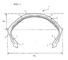
- the figure 1 represents a tire 1 comprising a carcass reinforcement consisting of a single layer 2 comprising textile-type reinforcing elements.
- the layer 2 consists of reinforcing elements arranged radially.
- the radial positioning of the reinforcing elements is defined by the angle of application of said reinforcing elements; a radial arrangement corresponds to an angle of application of said elements with respect to the longitudinal direction of the tire of between 65 ° and 90 °.
- Said carcass layer 2 is anchored on each side of the tire 1 in a bead 3 whose base is intended to be mounted on a rim seat.
- Each bead 3 is extended radially outwardly by a sidewall 4, said sidewall 4 radially outwardly joining the tread 5.
- the tire 1 thus formed has a curvature value greater than 0.15 and preferably greater than 0.3.
- the curvature value is defined by the ratio Ht / Wt, that is to say by the ratio of the height of the tread on the maximum width of the tread of the tire.
- the value of curvature will advantageously be between 0.25 and 0.5 for a tire intended to be mounted at the front of a motorcycle and it will advantageously be between 0.2 and 0.5 for a tire intended to be mounted at the rear.
- the tire 1 further comprises a crown reinforcement 6 consisting of two layers 7 and 8 of reinforcing elements making angles with the circumferential direction; said reinforcing elements being crossed from one layer to the next by making between them angles equal to 50 ° in the region of the equatorial plane, the reinforcing elements of each of the layers 7 and 8 forming an angle equal to 25 ° with the circumferential direction.
- a crown reinforcement 6 consisting of two layers 7 and 8 of reinforcing elements making angles with the circumferential direction; said reinforcing elements being crossed from one layer to the next by making between them angles equal to 50 ° in the region of the equatorial plane, the reinforcing elements of each of the layers 7 and 8 forming an angle equal to 25 ° with the circumferential direction.
- the reinforcing elements of the two layers 7 and 8 are made of textile material and more precisely aramid.
- the density of reinforcing elements in the radially innermost layer 7 is equal to 95 threads / dm (threads per decimeter).
- the density of reinforcement elements in the radially outermost layer 8 is equal to 45 threads / dm.
- the density of reinforcing elements of the radially innermost layer 7 is greater than the density of reinforcement elements of the radially outermost layer 8.
- Tests have been carried out with such a 120 / 70R17 tire and compared with those made with a standard tire of the same dimension consisting of a similar architecture, the two working layers having reinforcing element densities identical to and equal to 70 threads / dm and reinforcing elements having identical angles to those of the tire according to the invention.
- the standard tire used for the comparison thus has an overall stiffness, defined in particular by the sum of the densities of reinforcement elements of the working layers, identical to that of the tire according to the invention.
- the second type of testing is quantitative. It consisted in determining the distance traveled by each of the tires on test machines simulating a running in a straight line with an imposed load.
- the tire according to the invention has a gain in distance traveled of the order of 4% compared to the distance traveled by the standard reference tire.
- FIG. 2 On the figure 2 , is shown a tire 21 similar to that of the figure 1 and which differs in the presence of a layer of circumferential reinforcing elements 29 radially outside the layers 27, 28 of the crown reinforcement 26.
- the layer of circumferential reinforcing elements 29 is thus the part of the radially outer crown reinforcement and the two working layers 27, 28 are interposed between the carcass layer 22 and the layer of circumferential reinforcing elements 29.
- the layer of circumferential reinforcing elements is advantageously constituted of a single wire wound to form an angle with the longitudinal direction substantially equal to 0 °.
- the layer of circumferential reinforcing elements can be further achieved by the simultaneous winding of several bare wires or in the form of strips when embedded in rubber.
- the working layers 27, 28 consist of textile reinforcements and are made according to the invention, the density of reinforcement elements of the radially innermost layer 27 being greater than the density of reinforcing elements of the invention. the layer 28.
- the invention should of course not be interpreted in a limiting manner in view of these two exemplary embodiments.
- the variation in stiffness of extension per unit width of a working layer measured in the main direction of the reinforcing elements of said layer can also be obtained by example by differences in diameter of the reinforcing elements or even by a combination of different means.
- the invention also extends to tires which may comprise more complex crown reinforcements comprising, for example, three or more working layers of reinforcement elements forming an angle with the circumferential direction.
- the invention also applies to the various cases of vertex reinforcement previously described and in particular described in the patent applications WO 2004/018236 , WO 2004/018237 , WO 2005/070704 , WO 2005/070706 , in particular having the different radial positions of the layers constituting the crown reinforcement with respect to each other, as well as their radial position with respect to the carcass structure, as well as the constitution of a layer formed by a wire constituting sections connected by loops or the variation of the angles of said sections in the axial direction.
Abstract
Description
L'invention concerne un pneumatique destiné à équiper un véhicule et plus particulièrement destiné à équiper un véhicule à deux roues tel qu'une motocyclette.The invention relates to a tire intended to equip a vehicle and more particularly intended to equip a two-wheeled vehicle such as a motorcycle.
Bien que non limité à une telle application, l'invention sera plus particulièrement décrite en référence à un tel pneumatique de motocyclette, ou moto.Although not limited to such an application, the invention will be more particularly described with reference to such a motorcycle tire, or motorcycle.
L'armature de renforcement ou renforcement des pneumatiques et notamment des pneumatiques de motocyclette est à l'heure actuelle - et le plus souvent - constituée par empilage d'une ou plusieurs nappes désignées classiquement « nappes de carcasse », «nappes sommet », etc. Cette façon de désigner les armatures de renforcement provient du procédé de fabrication, consistant à réaliser une série de produits semi-finis en forme de nappes, pourvues de renforts filaires souvent longitudinaux, qui sont par la suite assemblées ou empilées afin de confectionner une ébauche de pneumatique. Les nappes sont réalisées à plat, avec deys, dimensions importantes, et sont par la suite coupées en fonction des dimensions d'un produit donné. L'assemblage des nappes est également réalisé, dans un premier temps, sensiblement à plat. L'ébauche ainsi réalisée est ensuite mise en forme pour adopter le profil toroïdal typique des pneumatiques. Les produits semi-finis dits « de finition » sont ensuite appliqués sur l'ébauche, pour obtenir un produit prêt pour la vulcanisation.The reinforcing or reinforcing armature for tires and especially motorcycle tires is at present - and most often - constituted by stacking one or more plies conventionally referred to as "carcass plies", "crown plies", etc. . This method of designating reinforcing reinforcements comes from the manufacturing process, consisting in producing a series of semi-finished products in the form of plies, provided with wire reinforcements, often longitudinal, which are subsequently assembled or stacked in order to make a rough draft. pneumatic. The sheets are made flat, with deys, large dimensions, and are subsequently cut according to the dimensions of a given product. The assembly of the plies is also made, initially, substantially flat. The blank thus produced is then shaped to adopt the typical toroidal profile of the tires. The so-called "finished" semi-finished products are then applied to the blank to obtain a product ready for vulcanization.
Un tel type de procédé "classique" implique, en particulier pour la phase de fabrication de l'ébauche du pneumatique, l'utilisation d'un élément d'ancrage (généralement une tringle), utilisée pour réaliser l'ancrage ou le maintien de l'armature de carcasse dans la zone des bourrelets du pneumatique. Ainsi, pour ce type de procédé, on effectue un retournement d'une portion de toutes les nappes composant l'armature de carcasse (ou d'une partie seulement) autour d'une tringle disposée dans le bourrelet du pneumatique. On crée de la sorte un ancrage de l'armature de carcasse dans le bourrelet.Such a type of "conventional" method involves, in particular for the manufacturing phase of the blank of the tire, the use of an anchoring element (generally a bead wire), used to carry out the anchoring or the maintenance of the carcass reinforcement in the area of the beads of the tire. Thus, for this type of process, a portion of all the plies constituting the carcass reinforcement (or of a part only) is turned around around a bead wire disposed in the bead of the tire. In this way, an anchoring of the carcass reinforcement in the bead is created.
La généralisation dans l'industrie de ce type de procédé classique, malgré de nombreuses variantes dans la façon de réaliser les nappes et les assemblages, a conduit l'homme du métier à utiliser un vocabulaire calqué sur le procédé ; d'où la terminologie généralement admise, comportant notamment les termes «nappes», «carcasse», «tringle», «conformation» pour désigner le passage d'un profil plat à un profil toroïdal, etc.The generalization in industry of this type of conventional method, despite many variations in the manner of making the plies and assemblies, led the skilled person to use a vocabulary modeled on the process; hence the generally accepted terminology, including in particular the terms "plies", "carcass", "rod", "conformation" to designate the passage from a flat profile to a toroidal profile, etc.
Il existe aujourd'hui des pneumatiques qui ne comportent à proprement parler pas de «nappes» ou de «tringles» d'après les définitions précédentes. Par exemple, le document
Par ailleurs, les pneumatiques décrits dans ce document ne disposent pas du "traditionnel" retournement de nappe carcasse autour d'une tringle. Ce type d'ancrage est remplacé par un agencement dans lequel on dispose de façon adjacente à ladite structure de renfort de flanc des fils circonférentiels, le tout étant noyé dans un mélange caoutchouteux d'ancrage ou de liaison.Moreover, the tires described in this document do not have the "traditional" reversal of carcass ply around a rod. This type of anchorage is replaced by an arrangement in which is disposed adjacent to said sidewall reinforcing structure circumferential son, all being embedded in a rubber mix anchoring or bonding.
Il existe également des procédés d'assemblage sur noyau toroïdal utilisant des produits semi-finis spécialement adaptés pour une pose rapide, efficace et simple sur un noyau central. Enfin, il est également possible d'utiliser un mixte comportant à la fois certains produits semi-finis pour réaliser certains aspects architecturaux (tels que des nappes, tringles, etc), tandis que d'autres sont réalisés à partir de l'application directe de mélanges et/ou d'élément de renforcement.There are also toroidal core assembly methods using semi-finished products specially adapted for fast, efficient and simple laying on a central core. Finally, it is also possible to use a combination of both semi-finished products to achieve certain architectural aspects (such as tablecloths, rods, etc.), while others are made from direct application mixtures and / or reinforcing element.
Dans le présent document, afin de tenir compte des évolutions technologiques récentes tant dans le domaine de la fabrication que pour la conception de produits, les termes classiques tels que «nappes», «tringles», etc, sont avantageusement remplacés par des termes neutres ou indépendants du type de procédé utilisé. Ainsi, le terme «renfort de type carcasse» ou «renfort de flanc» est valable pour désigner les éléments de renforcement d'une nappe carcasse dans le procédé classique, et les éléments de renforcement correspondants, en général appliqués au niveau des flancs, d'un pneumatique produit selon un procédé sans semi-finis. Le terme «zone d'ancrage», pour sa part, peut désigner tout autant le "traditionnel" retournement de nappe carcasse autour d'une tringle d'un procédé classique, que l'ensemble formé par les éléments de renforcement circonférentiels, le mélange caoutchouteux et les portions adjacentes de renfort de flanc d'une zone basse réalisée avec un procédé avec application sur un noyau toroïdal.In this document, to take into account recent technological developments in both manufacturing and design of products, the conventional terms such as "plies", "rods", etc., are advantageously replaced by terms that are neutral or independent of the type of process used. Thus, the term "carcass-type reinforcement" or "sidewall reinforcement" is used to designate the reinforcement elements of a carcass ply in the conventional method, and the corresponding reinforcing elements, generally applied at the flanks, to the carcass ply. a tire produced according to a process without semi-finished. The term "anchoring zone", for its part, can refer to both the "traditional" reversal of carcass ply around a rod of a conventional process, that the assembly formed by the circumferential reinforcing elements, the mixture rubbery and adjacent portions of sidewall reinforcement of a low zone made with a method with application to a toroidal core.
La direction longitudinale du pneumatique, ou direction circonférentielle, est la direction correspondant à la périphérie du pneumatique et définie par la direction de roulement du pneumatique.The longitudinal direction of the tire, or circumferential direction, is the direction corresponding to the periphery of the tire and defined by the rolling direction of the tire.
Un plan circonférentiel ou plan circonférentiel de coupe est un plan perpendiculaire à l'axe de rotation du pneumatique. Le plan équatorial est le plan circonférentiel passant par le centre ou sommet de la bande de roulement.A circumferential plane or circumferential plane of section is a plane perpendicular to the axis of rotation of the tire. The equatorial plane is the circumferential plane passing through the center or crown of the tread.
La direction transversale ou axiale du pneumatique est parallèle à l'axe de rotation du pneumatique.The transverse or axial direction of the tire is parallel to the axis of rotation of the tire.
La direction radiale est une direction coupant l'axe de rotation du pneumatique et perpendiculaire à celui-ci.The radial direction is a direction intersecting the axis of rotation of the tire and perpendicular to it.
L'axe de rotation du pneumatique est l'axe autour duquel il tourne en utilisation normale.The axis of rotation of the tire is the axis around which it rotates under normal use.
Un plan radial ou méridien contient l'axe de rotation du pneumatique.A radial or meridian plane contains the axis of rotation of the tire.
Comme dans le cas de tous les autres pneumatiques, on assiste à une radialisation des pneumatiques pour motos, l'architecture de tels pneumatiques comprenant une armature de carcasse formée d'une ou deux couches d'éléments de renforcement faisant avec la direction circonférentielle un angle pouvant être compris entre 65° et 90°, ladite armature de carcasse étant radialement surmontée d'une armature de sommet formée d'éléments de renforcement. Il subsiste toutefois des pneumatiques non radiaux auquel se rapporte également l'invention. L'invention se rapporte encore à des pneumatiques partiellement radiaux, c'est-à-dire dont les éléments de renforcement de l'armature de carcasse sont radiaux sur au moins une partie de ladite armature de carcasse, par exemple dans la partie correspondant au sommet du pneumatique.As in the case of all other tires, there is a radialization of tires for motorcycles, the architecture of such tires comprising a carcass reinforcement formed of one or two layers of elements of reinforcing making with the circumferential direction an angle which can be between 65 ° and 90 °, said carcass reinforcement being radially surmounted by a crown reinforcement formed of reinforcing elements. There are, however, non-radial tires to which the invention also relates. The invention also relates to partially radial tires, that is to say the reinforcing elements of the carcass reinforcement are radial on at least a portion of said carcass reinforcement, for example in the portion corresponding to the top of the tire.
De nombreuses architectures d'armature de sommet ont été proposées, selon que le pneumatique sera destiné à la monte à l'avant de la moto ou à la monte à l'arrière. Une première structure consiste, pour ladite armature de sommet, à employer uniquement des câbles circonférentiels, et ladite structure est plus particulièrement employée pour la position carrière. Une deuxième structure, directement inspirée des structures couramment employées en pneumatiques pour véhicules de Touriste, a été utilisée pour améliorer la résistance à l'usure, et consiste dans l'utilisation d'au moins deux couches de sommet de travail d'éléments de renforcement sensiblement parallèles entre eux dans chaque couche mais croisés d'une couche à la suivante en faisant avec la direction circonférentielle des angles aigus, de tels pneumatiques étant plus particulièrement adaptés pour l'avant des motos. Les dites deux couches de sommet de travail peuvent être associées à au moins une couche d'éléments circonférentiels, généralement obtenus par enroulement hélicoïdal d'une bandelette d'au moins un élément de renforcement enrobé de caoutchouc.Many crown reinforcement architectures have been proposed, depending on whether the tire will be for riding at the front of the motorcycle or for riding at the rear. A first structure consists, for said crown reinforcement, in using only circumferential cables, and said structure is more particularly used for the career position. A second structure, directly inspired by the structures commonly used in passenger car tires, has been used to improve the wear resistance, and consists in the use of at least two layers of working crown of reinforcing elements. substantially parallel to each other in each layer but crossed from one layer to the next making sharp angles with the circumferential direction, such tires being more particularly adapted for the front of the motorcycles. Said two working crown layers may be associated with at least one layer of circumferential elements, generally obtained by helically winding a strip of at least one rubber-coated reinforcing element.
Le choix des architectures de sommet des pneumatiques intervient directement sur certaines propriétés des pneumatiques telles que l'usure, l'endurance, l'adhérence ou bien encore le confort en roulage ou dans les cas notamment des motocyclettes la stabilité. Toutefois d'autres paramètres des pneumatiques tels que la nature des mélanges caoutchouteux constituant la bande de roulement interviennent également sur les propriétés dudit pneumatique. Le choix et la nature des mélanges caoutchouteux, constituant la bande de roulement sont par exemple des paramètres essentiels concernant les propriétés d'usure. Le choix et la nature des mélanges caoutchouteux constituant la bande de roulement interviennent également sur les propriétés d'adhérence du pneumatique.The choice of tire vertex architectures directly affects certain properties of the tires such as wear, endurance, grip or even comfort when driving or in cases including motorcycles stability. However, other tire parameters such as the nature of the rubber compounds constituting the tread also affect the properties of said tire. The choice and the nature of the rubber compounds constituting the tread are, for example, essential parameters relating to the wear properties. The choice and the nature of the mixtures rubbery constituent the tread also affect the adhesion properties of the tire.
L'invention a pour but de fournir un pneumatique permettant d'améliorer les propriétés d'usure du pneumatique et d'améliorer des propriétés d'adhérence de la bande de roulement dudit pneumatique, notamment lors de passage de courbe dans le cas de pneumatiques pour motocyclette.The aim of the invention is to provide a tire making it possible to improve the wear properties of the tire and to improve the adhesion properties of the tread of said tire, in particular during curve crossing in the case of tires for the tire. motorcycle.
Ce but a été atteint selon l'invention par un pneumatique comportant une structure de renfort de type carcasse, formée d'éléments de renforcement, ancrée de chaque côté du pneumatique à un bourrelet dont la base est destinée à être montée sur un siège de jante, chaque bourrelet se prolongeant radialement vers l'extérieur par un flanc, les flancs rejoignant radialement vers l'extérieur une bande de roulement, et comportant sous la bande de roulement une structure de renforcement de sommet constituée d'au moins deux couches d'éléments de renforcement dite couches de travail, lesdits éléments de renforcement des couches de travail étant de nature identique, et dans un plan circonférentiel donné, la rigidité d'extension par unité de largeur d'une première couche de travail mesurée selon la direction principale des éléments de renforcement de ladite première couche étant strictement supérieure à la rigidité d'extension par unité de largeur d'une deuxième couche de travail mesurée selon la direction principale des éléments de renforcement de ladite deuxième couche de travail, la deuxième couche de travail étant radialement plus éloignée de la structure de carcasse que ladite première couche de travail.This object has been achieved according to the invention by a tire comprising a carcass-type reinforcement structure, formed of reinforcement elements, anchored on each side of the tire to a bead whose base is intended to be mounted on a rim seat. , each bead extending radially outwardly by a sidewall, the flanks joining radially outwardly a tread, and having under the tread a crown reinforcement structure consisting of at least two layers of elements said working layer reinforcing elements being identical in nature, and in a given circumferential plane, the extension stiffness per unit width of a first working layer measured in the main direction of the elements reinforcing said first layer being strictly greater than the extension stiffness per unit width of a second working layer measured in the main direction of the reinforcing elements of said second working layer, the second working layer being radially further away from the carcass structure than said first working layer.
Selon l'invention, dés couches de travail sont des couches d'élément de renforcement présentant, au moins dans la partie centrale de la bande de roulement, des angles avec la direction circonférentielles compris entre 10 et 80°.According to the invention, working layers are reinforcing element layers having, at least in the central portion of the tread, angles with the circumferential direction of between 10 and 80 °.
La zone centrale est une zone ou bande périphérique centrée sur le sommet de la bande de roulement lui même défini par le plan équatorial du pneumatique.The central zone is a peripheral zone or band centered on the crown of the tread itself defined by the equatorial plane of the tire.
Au sens de l'invention, la nature des éléments de renforcement est le matériau les constituant.Within the meaning of the invention, the nature of the reinforcing elements is the material constituting them.
La direction principale des éléments de renforcement est définie par la direction de la tangente aux éléments de renforcement au point d'intersection des éléments de renforcement et du plan circonférentiel donné.The principal direction of the reinforcing elements is defined by the direction of the tangent to the reinforcing elements at the point of intersection of the reinforcing elements and the given circumferential plane.
L'unité de largeur est définie au sens de l'invention selon une direction perpendiculaire à la direction principale des éléments de renforcement.The width unit is defined in the sense of the invention in a direction perpendicular to the main direction of the reinforcing elements.
La rigidité d'extension d'une couche d'éléments de renforcement est la propriété de la dite couche d'éléments de renforcement reliant une contrainte supportée par ladite couche et la déformation correspondante de ladite couche.The stiffness of extension of a layer of reinforcing elements is the property of said layer of reinforcing elements connecting a stress supported by said layer and the corresponding deformation of said layer.
Un pneumatique ainsi réalisé selon l'invention et comportant une deuxième couche radialement plus éloignée de la structure de carcasse que la première couche, confère d'une part une rigidité radiale de la bande de roulement moins importante ; une telle propriété de la bande de roulement du pneumatique permet d'augmenter la surface de contact, ou aire de contact, de ladite bande de roulement avec le sol lors d'un roulage et ainsi d'optimiser à la fois la transmission des couples accélérateurs et freineurs tout en améliorant les propriétés en termes d'usure de la bande de roulement.A tire thus produced according to the invention and comprising a second layer radially further from the carcass structure than the first layer, on the one hand, gives a lower radial rigidity of the tread; such a property of the tread of the tire makes it possible to increase the contact surface, or contact area, of said tread with the ground during a running and thus to optimize both the transmission of accelerating torques and brakes while improving the properties in terms of tread wear.
D'autre part, la réalisation d'un pneumatique conformément à l'invention confère des rigidités circonférentielles et axiales supérieures au pneumatique et donc une meilleure tenue ou de meilleures performances d'adhérence, notamment lors de passages de courbes. Ces rigidités circonférentielles et axiales supérieures selon l'invention, pour des rigidités circonférentielles et axiales globales données, sont une conséquence de l'accroissement de la rigidité de la couche de travail radialement la plus proche de la structure de carcasse, et donc participant le plus efficacement auxdites rigidités circonférentielles et axiales.On the other hand, the production of a tire according to the invention confers superior circumferential and axial stiffnesses to the tire and therefore a better performance or better adhesion performance, especially during curve passes. These circumferential and upper axial stiffnesses according to the invention, for given overall circumferential and axial stiffnesses, are a consequence of the increase in the stiffness of the working layer radially closest to the carcass structure, and therefore the most important participant. effectively to said circumferential and axial stiffnesses.
Conformément à l'invention, lorsque le pneumatique comporte plus de deux couches de travail, la rigidité d'extension par unité de largeur des couches de travail mesurée selon la direction principale des éléments de renforcement desdites couches diminue graduellement lorsque la distance radiale entre la couche de travail et la structure de carcasse augmente. En d'autres termes, par exemple dans le cas de trois couches de travail, la rigidité d'extension par unité de largeur de la troisième couche de travail mesurée selon la direction principale des éléments de renforcement de ladite troisième couche est strictement inférieure à la rigidité d'extension par unité de largeur de la deuxième couche de travail mesurée selon la direction principale des éléments de renforcement de ladite deuxième couche de travail, la deuxième couche de travail étant radialement moins éloignée de la structure de carcasse que ladite troisième couche de travail et la deuxième couche de travail étant radialement plus éloignée de la structure de carcasse qu'une première couche de travail, ladite première couche de travaille présentant une rigidité d'extension par unité de largeur mesurée selon la direction principale des éléments de renforcement de ladite première couche strictement supérieure à la rigidité d'extension par unité de largeur de ladite deuxième couche de travail mesurée selon la direction principale des éléments de renforcement de ladite deuxième couche de travail.According to the invention, when the tire comprises more than two working layers, the extension stiffness per unit width of the working layers measured along the principal direction of the reinforcing elements of said layers decreases gradually when the radial distance between the layer work and carcass structure increases. In other words, for example in the case of three layers, the extension stiffness per unit width of the third working layer measured along the principal direction of the reinforcing elements of said third layer is strictly less than the extension stiffness per unit width of the second layer of work measured in the main direction of the reinforcement elements of said second working layer, the second working layer being radially less distant from the carcass structure than said third working layer and the second working layer being radially further away from the structure a first working layer, said first working layer having an extension stiffness per unit width measured in the main direction of the reinforcing elements of said first layer strictly greater than the extension stiffness per unit width of said second measured working layer in the main direction of the reinforcing elements of said second working layer.
Selon un premier mode de réalisation de l'invention, les diamètres des éléments de renforcement de la première couche de travail sont plus grands que les diamètres des éléments de renforcement de la deuxième couche de travail.According to a first embodiment of the invention, the diameters of the reinforcing elements of the first working layer are larger than the diameters of the reinforcing elements of the second working layer.
Selon un deuxième mode de réalisation de l'invention, la densité d'éléments de renforcement de la première couche de travail est plus grande que la densité d'éléments de renforcement de la deuxième couche de travail.According to a second embodiment of the invention, the density of reinforcing elements of the first working layer is greater than the density of reinforcement elements of the second working layer.
Selon d'autres modes de réalisation de l'invention, la différence de rigidité entre les couches de travail peut encore être obtenue par une combinaison des deux modes de réalisation de réalisations ci-dessus présentés.According to other embodiments of the invention, the difference in stiffness between the working layers can still be obtained by a combination of the two embodiments of embodiments shown above.
Selon l'un ou l'autre de ces modes de réalisation de l'invention, au moins dans la zone centrale de la bande de roulement et dans un plan circonférentiel donné, la valeur absolue des angles formés avec la direction circonférentielle par les éléments de renforcement des différentes couches de travail sont différents d'une couche de travail à l'autre. Les essais ont également montré que des variations d'angles des éléments de renforcement d'une couche de travail à une autre peuvent également permettre de modifier les rigidités du pneumatique.According to one or other of these embodiments of the invention, at least in the central zone of the tread and in a given circumferential plane, the absolute value of the angles formed with the circumferential direction by the elements of reinforcement of different working layers are different from one working layer to another. The tests have also shown that variations of angles of the reinforcing elements from one working layer to another may also make it possible to modify the stiffnesses of the tire.
Selon une variante de réalisation préféré de l'invention, au moins dans la zone centrale de la bande de roulement, les éléments de renforcements d'une couche de travail présentent des angles, formés avec la direction longitudinale, identiques, lesdits angles étant mesurés aux points d'intersections avec un plan circonférentiel, quel que soit ledit plan circonférentiel. En d'autres termes, pour un plan circonférentiel de coupe donné, les éléments de renforcement présentent tous le même angle formé avec la direction longitudinale aux points d'intersections avec ledit plan circonférentiel de coupe. Par ailleurs, l'angle précité peut varier selon le plan circonférentiel de coupe considéré.According to a preferred embodiment of the invention, at least in the central zone of the tread, the reinforcement elements of a working layer have identical angles, formed with the longitudinal direction, said angles being measured at intersection points with a circumferential plane, regardless of said circumferential plane. In other words, for a given circumferential sectional plane, the reinforcing elements all have the same angle formed with the longitudinal direction at the points of intersection with said circumferential cutting plane. Moreover, the aforementioned angle may vary according to the circumferential section plane considered.
Selon une réalisation préférée de l'invention, au moins dans la zone centrale de la bande de roulement, les éléments de renforcement sont équidistants les uns des autres selon tous plans circonférentiels; la distance séparant des éléments de renforcement adjacents pouvant quant à elle varier selon le plan circonférentiel de coupe considéré, ou plus précisément, la distance entre des éléments de renforcement adjacents pouvant varier selon la direction axiale.According to a preferred embodiment of the invention, at least in the central zone of the tread, the reinforcing elements are equidistant from each other in all circumferential planes; the distance separating adjacent reinforcing elements that can in turn vary according to the circumferential plane of section considered, or more precisely, the distance between adjacent reinforcing elements that can vary in the axial direction.
De préférence encore, au moins dans la zone centrale de la bande de roulement, les éléments de renforcement de deux couches de travail radialement adjacentes forment entre eux des angles compris entre 20 et 160°.More preferably, at least in the central region of the tread, the reinforcing elements of two radially adjacent working layers form between them angles between 20 and 160 °.
Une variante de réalisation de l'invention prévoit qu'au moins une couche de travail est réalisée au moins partiellement radialement à l'intérieur de la structure de renfort de type carcasse.An alternative embodiment of the invention provides that at least one working layer is made at least partially radially inside the carcass-type reinforcement structure.
Selon un premier mode de réalisation de l'invention, l'ensemble des couches de travail est réalisé radialement à l'intérieur d'au moins une structure de carcasse, c'est-à-dire à l'intérieur d'au moins une couche de carcasse. Au moins une structure de renfort de type carcasse couvre ainsi radialement la structure complète de renforcement de sommet.According to a first embodiment of the invention, the set of working layers is made radially inside at least one carcass structure, that is to say within at least one carcass layer. At least one carcass-type reinforcement structure thus radially covers the complete crown reinforcement structure.
Selon un second mode de réalisation préféré de l'invention, au moins une couche d'éléments de renforcement de travail de la structure de renforcement de sommet est réalisée radialement à l'extérieur de la structure de renfort de type carcasse. Selon ce second mode de réalisation de l'invention, la couche d'éléments de renforcement de travail assume une fonction de protection à l'égard de la carcasse et des autres couches de la structure de renforcement de sommet, contre des agressions mécaniques éventuelles.According to a second preferred embodiment of the invention, at least one layer of work reinforcing elements of the reinforcement structure of vertex is made radially outside the carcass-type reinforcement structure. According to this second embodiment of the invention, the layer of work reinforcing elements assumes a protective function with respect to the carcass and the other layers of the crown reinforcement structure, against possible mechanical aggression.
Dans une variante avantageuse de l'invention, une couche d'éléments de renforcement de travail peut être réalisée en plusieurs parties mises en place en différentes positions radiales ou différents niveaux du pneumatique. Un tel pneumatique peut notamment comporter une partie de la couche d'éléments de renforcement de travail radialement à l'extérieur des éléments de renforcement de la structure de carcasse dans la partie centrale du pneumatique, c'est-à-dire sous la partie centrale de la bande de roulement. Cette partie de la couche d'éléments de renforcement de travail permet alors notamment une protection de la carcasse contre d'éventuelles agressions pouvant intervenir par la partie centrale de la bande de roulement, considérée comme la plus exposée. L'invention prévoit encore, dans le cas d'une couche d'éléments de renforcement de travail réalisée en plusieurs parties mises en place en différentes positions radiales, que la répartition de ces différentes parties ne soit pas réalisée de manière symétrique par rapport au plan équatorial, ou plan circonférentiel passant par le centre du sommet du pneumatique.In an advantageous variant of the invention, a layer of work reinforcing elements can be made in several parts placed in different radial positions or different levels of the tire. Such a tire may in particular comprise a part of the layer of reinforcing elements working radially outside the reinforcing elements of the carcass structure in the central part of the tire, that is to say under the central part. of the tread. This part of the layer of work reinforcing elements then allows in particular a protection of the carcass against possible attacks that may occur through the central portion of the tread, considered the most exposed. The invention further provides, in the case of a layer of work reinforcement elements made in several parts placed in different radial positions, that the distribution of these different parts is not carried out symmetrically with respect to the plane equatorial, or circumferential plane passing through the center of the crown of the tire.
Conformément à ce type de réalisation d'une couche d'éléments de renforcement de travail fractionnée en plusieurs parties, l'invention prévoit avantageusement un recouvrement des extrémités axiales desdites parties entre-elles.According to this type of embodiment of a layer of work reinforcement elements divided into several parts, the invention advantageously provides an overlap of the axial ends of said parts together.
Un pneumatique selon l'invention, notamment lorsqu'au moins une partie de la structure de renforcement de sommet est réalisée radialement à l'intérieur de la structure de carcasse, est avantageusement réalisé selon une technique de fabrication du type sur noyau dur ou forme rigide.A tire according to the invention, in particular when at least a part of the crown reinforcement structure is produced radially inside the carcass structure, is advantageously produced according to a manufacturing technique of the hard core or rigid form type. .
Selon une variante de réalisation de l'invention, au moins une couche d'éléments de renforcement de travail est constituée d'au moins un fil continu de renforcement formant dans la zone centrale de ladite couche des tronçons présentant des angles, formés avec la direction longitudinale, identiques, lesdits angles étant mesurés aux points d'intersections avec un plan circonférentiel, deux tronçons adjacents étant liés par une boucle, et les tronçons formant un angle avec la direction longitudinale compris entre 10 et 80°.According to an alternative embodiment of the invention, at least one layer of work-reinforcing elements consists of at least one continuous reinforcing wire forming in the central zone of said layer sections having angles, formed with the longitudinal direction, identical, said angles being measured at the points of intersection with a circumferential plane, two adjacent sections being connected by a loop, and the sections forming an angle with the longitudinal direction of between 10 and 80 °.
Le terme « fil » désigne en toute généralité, aussi bien des mono-filaments, des fibres multifilamentaires (éventuellement tordues sur elles-mêmes) ou des assemblages comme des câbles textiles ou métalliques, des retors ou bien encore n'importe quel type d'assemblage équivalent, comme par exemple, un câble hybride, et ceci, quelle que soient la ou les matières, le traitement éventuel de ces fils, par exemple un traitement de surface ou enrobage, ou préencollage, pour favoriser l'adhésion sur le caoutchouc ou toute autre matière.The term "wire" generally refers to both mono-filaments, multifilamentary fibers (possibly twisted on themselves) or assemblies such as textile or metal cords, twists or any type of equivalent assembly, such as for example a hybrid cable, and this, whatever the material or materials, the possible treatment of these son, for example a surface treatment or coating, or pre-gluing, to promote adhesion to the rubber or any other matter.
Selon cette variante avantageuse de l'invention, la couche de travail est réalisée avec au moins un fil dont aucune extrémité libre n'est présente sur les bords de ladite couche. De préférence, la réalisation de la couche est faite avec un seul fil et la couche est du type « mono-fil ». Toutefois, la réalisation industrielle de telles couches conduit à des discontinuités notamment dues à des changements de bobine. Une réalisation préférée de l'invention consiste encore à n'utiliser qu'un seul ou un faible nombre de fils pour une couche de travail et il convient de disposer les débuts et fins de fils dans la zone centrale de ladite couche.According to this advantageous variant of the invention, the working layer is made with at least one wire of which no free end is present on the edges of said layer. Preferably, the embodiment of the layer is made with a single wire and the layer is of the "single-wire" type. However, the industrial production of such layers leads to discontinuities, in particular due to coil changes. A preferred embodiment of the invention is still to use only one or a small number of son for a working layer and it is appropriate to have the beginnings and ends of son in the central zone of said layer.
Un pneumatique selon l'invention ainsi réalisé comporte une structure de renforcement qui ne présente aucune extrémité libre des éléments de renforcement au niveau des bords axialement extérieurs des couches de travail.A tire according to the invention thus produced comprises a reinforcing structure which has no free end of the reinforcing elements at the axially outer edges of the working layers.
Les études réalisées ont notamment mis en évidence que la présence de couches usuelles d'éléments de renforcement présentant un angle avec la direction longitudinale conduit à des rigidités locales, circonférentielles et de cisaillement, qui diminuent à l'approche des bords desdites couche, la tension aux extrémités des éléments de renforcement étant nulle. Une tension locale nulle des éléments de renforcement se traduit par une moindre efficacité desdits éléments de renforcement dans cette zone. Or, les rigidités des bords des couches sont particulièrement importantes lorsque le pneumatique est utilisé dans les plus forts carrossages, en courbe, la partie du pneumatique correspondant à ces zones se trouvant alors en regard du sol.The studies carried out have in particular demonstrated that the presence of usual layers of reinforcing elements having an angle with the longitudinal direction leads to local, circumferential and shear stiffnesses, which diminish when approaching the edges of said layer, the tension at the ends of the reinforcing elements being zero. A zero local voltage of the reinforcing elements results in a lower efficiency of said reinforcing elements in this area. However, the rigidities of the edges of the layers are particularly important when the tire is used in the strongest camber, curved, the portion of the tire corresponding to these areas then being facing the ground.
La réalisation de pneumatiques pour motocyclettes conduit à des valeurs de courbures importantes pour une utilisation desdits pneumatiques en carrossage. Un pneumatique réalisé selon cette variante de l'invention et qui comporte une structure de renforcement qui ne présente aucune extrémité libre des éléments de renforcement au niveau des bords axialement extérieurs des couches de travail, permet ainsi notamment de renforcer les propriétés d'adhérence et de motricité des pneumatiques pour une utilisation en fort carrossage.The production of tires for motorcycles leads to significant curvature values for use of said tires in camber. A tire produced according to this variant of the invention and which comprises a reinforcing structure which has no free end of the reinforcing elements at the axially outer edges of the working layers, thus makes it possible in particular to reinforce the properties of adhesion and adhesion. traction of tires for use in strong camber.
Un tel pneumatique est avantageusement réalisé selon une technique du type sur noyau dur ou toroïdal qui autorise notamment la mise en place des éléments de renforcement dans la position quasi-finale ; en effet, une étape de conformation n'étant pas requise selon ce type de procédé les éléments de renforcement ne sont plus déplacés après leur mise en place.Such a tire is advantageously made according to a technique of the type on hard or toroidal core which allows in particular the establishment of reinforcement elements in the near-final position; indeed, a conformation step is not required according to this type of method the reinforcing elements are no longer moved after their introduction.
Dans une réalisation avantageuse de l'invention, notamment pour optimiser encore les rigidités de la structure de renforcement le long du méridien du pneumatique, et en particulier aux bords des couches de travail, les angles formés par lesdits tronçons du fil des couches de travail avec la direction longitudinale sont variables selon la direction transversale tels que lesdits angles sont supérieurs sur les bords axialement extérieurs des couches d'éléments de renforcement par rapport aux angles desdits tronçons mesurés au niveau du plan équatorial du pneumatique.In an advantageous embodiment of the invention, in particular to further optimize the rigidities of the reinforcing structure along the meridian of the tire, and in particular at the edges of the working layers, the angles formed by said sections of the thread of the working layers with the longitudinal direction are variable in the transverse direction such that said angles are greater on the axially outer edges of the reinforcing element layers with respect to the angles of said sections measured at the equatorial plane of the tire.
L'utilisation d'une technique du type sur noyau dur qui autorise notamment la mise en place des éléments de renforcement dans la position quasi-finale sans nécessiter d'étape de conformation présente encore des avantages. En effet, une technique du type sur noyau dur autorise notamment de manière simple des variations d'angles nettement supérieures à ce qu'il est possible d'obtenir selon des procédés comportant une étape de conformation. En outre, lesdites variations d'angle, ledit angle tendant vers 90° aux bords des couches de travail, conduit à une augmentation du pas et favorise la réalisation des boucles, du fait de la réduction de l'encombrement.The use of a hard core type technique that allows in particular the establishment of reinforcement elements in the near-final position without requiring a conformation step still has advantages. Indeed, a technique of the hard core type in particular allows simple variations of angles much greater than what is possible to obtain according to methods comprising a conformation step. In addition, said angle variations, said angle tending to 90 ° to the edges of the working layers, leads to an increase in pitch and promotes the production of loops, because of the reduction in size.
Un premier mode de réalisation des variantes de réalisation de l'invention selon lesquelles les angles formés par lesdits tronçons du fil des couches de travail avec la direction longitudinale sont variables selon la direction transversale, consiste à faire varier l'angle des tronçons d'une manière monotone depuis le plan équatorial du pneumatique jusqu'aux bords de la couche de travail.A first embodiment of the embodiments of the invention according to which the angles formed by said sections of the wire of the working layers with the longitudinal direction are variable in the transverse direction, consists in varying the angle of the sections of a monotonically from the equatorial plane of the tire to the edges of the working layer.
Un second mode de réalisation de ces variantes consiste à faire évoluer l'angle par palier depuis le plan équatorial du pneumatique jusqu'aux bords de la couche de travail.A second embodiment of these variants is to change the angle stepwise from the equatorial plane of the tire to the edges of the working layer.
Un dernier mode de réalisation de ces variantes consiste en une évolution de l'angle telle que des valeurs données soient obtenues pour des positions axiales données.A final embodiment of these variants consists of an evolution of the angle such that given values are obtained for given axial positions.
Ces différents modes de réalisation des variantes de réalisation de l'invention selon lesquelles les angles formés par lesdits tronçons du fil des couches de travail avec la direction longitudinale sont variables selon la direction transversale permettent en d'autres termes, d'obtenir une forte rigidité circonférentielle de la structure de renforcement du sommet par la présence d'angles fermés, c'est-à-dire faibles, dans la zone du sommet du pneu, c'est-à-dire dans la zone encadrant le plan équatorial. Et au contraire la présence d'angles ouverts, c'est-à-dire d'angles tendant vers 45°, voir au-delà vers 90°, peut être obtenue sur les bords de la couche de travail ou plus exactement au niveau des épaules du pneumatique pour améliorer l'adhérence, la motricité, le confort, ou encore la température de fonctionnement du pneumatique ; en effet, de telles variations d'angles permettent de moduler les rigidités de cisaillement des couches de travail.These various embodiments of the embodiments of the invention according to which the angles formed by said sections of the wire of the working layers with the longitudinal direction are variable in the transverse direction allow in other words, to obtain a high rigidity circumferentially of the crown reinforcement structure by the presence of closed, i.e., small, angles in the area of the tire crown, i.e. in the area surrounding the equatorial plane. And on the contrary the presence of open angles, that is to say angles tending towards 45 °, see beyond 90 °, can be obtained on the edges of the working layer or more precisely at the level of tire shoulders to improve the grip, traction, comfort, or the operating temperature of the tire; in fact, such angle variations make it possible to modulate the shear stiffnesses of the working layers.
Selon une réalisation préférée de l'invention, les éléments de renforcement des couches de travail sont en matériau textile.According to a preferred embodiment of the invention, the reinforcing elements of the working layers are made of textile material.
Selon un autre mode de réalisation de l'invention, les éléments de renforcement des couches de travail sont en métal.According to another embodiment of the invention, the reinforcement elements of the working layers are made of metal.
Une réalisation préférée de l'invention prévoit que le pneumatique est notamment constitué d'une structure de renforcement de sommet qui comporte en outre au moins une couche d'éléments de renforcement circonférentiels ; selon l'invention, la couche d'éléments de renforcement circonférentiels est constituée d'au moins un élément de renforcement orienté selon un angle formé avec la direction longitudinale inférieur à 5°.A preferred embodiment of the invention provides that the tire comprises in particular a crown reinforcement structure which further comprises at least one layer of circumferential reinforcing elements; according to the invention, the layer of circumferential reinforcing elements consists of at least one reinforcing element oriented at an angle formed with the longitudinal direction less than 5 °.
La présence d'une couche d'éléments de renforcement circonférentiels est notamment préférable pour la réalisation d'un pneumatique destiné à être utilisé à l'arrière d'une motocyclette.The presence of a layer of circumferential reinforcing elements is particularly preferable for the production of a tire intended to be used in the rear of a motorcycle.
Une réalisation avantageuse de l'invention prévoit que la couche d'éléments de renforcement circonférentiels est positionnée au moins partiellement sur une couche de travail. Lorsque la couche d'éléments de renforcement circonférentiels est réalisée sur deux couches de travail et placée directement sous la bande de roulement, elle peut notamment contribuer à l'amélioration de la stabilité à haute vitesse.An advantageous embodiment of the invention provides that the layer of circumferential reinforcing elements is positioned at least partially on a working layer. When the layer of circumferential reinforcing elements is made on two working layers and placed directly under the tread, it can notably contribute to the improvement of stability at high speed.
La couche d'éléments de renforcement circonférentiels peut ainsi être réalisée directement sous la bande de roulement pour former outre sa fonction première une couche de protection de la carcasse et des autres couches de la structure de renforcement de sommet, contre des agressions mécaniques éventuelles.The layer of circumferential reinforcing elements can thus be made directly under the tread to form, in addition to its primary function, a protective layer of the carcass and the other layers of the crown reinforcement structure, against possible mechanical aggression.
La couche d'éléments de renforcement circonférentiels peut encore être réalisée entre les couches de travail, notamment par souci économique, la quantité de matière et le temps de pose étant ainsi diminués.The layer of circumferential reinforcing elements can also be produced between the working layers, in particular for economic reasons, the quantity of material and the exposure time thus being reduced.
Une autre réalisation avantageuse de l'invention prévoit que la couche d'éléments de renforcement circonférentiels est positionnée au moins partiellement radialement à l'intérieur de la couche de travail radialement la plus à l'intérieure. Selon cette réalisation, la couche d'éléments de renforcement circonférentiels est réalisée radialement à l'intérieur des couches de travail et peut notamment permettre d'améliorer l'adhérence et la motricité du pneumatique.Another advantageous embodiment of the invention provides that the layer of circumferential reinforcing elements is positioned at least partially radially within the radially innermost working layer. According to this embodiment, the layer of circumferential reinforcing elements is made radially inside the working layers and may in particular improve the adhesion and traction of the tire.
Une autre variante de l'invention prévoit qu'au moins une couche d'éléments de renforcement circonférentiels est positionnée au moins partiellement radialement à l'intérieur de la structure de renfort de type carcasse. Cette variante de réalisation peut encore reprendre les différents positionnements évoqués précédemment par rapport aux couches de travail. La carcasse peut ainsi couvrir la structure complète de renforcement de sommet. De préférence, l'invention prévoit qu'au moins une couche de renforcement de sommet est mise en place entre la carcasse et la bande de roulement pour assurer une protection de la carcasse.Another variant of the invention provides that at least one layer of circumferential reinforcing elements is positioned at least partially radially inside the carcass-type reinforcement structure. This variant embodiment can also take over the different positions mentioned above with respect to the working layers. The carcass can thus cover the complete crown reinforcement structure. Preferably, the invention provides that at least one crown reinforcement layer is placed between the carcass and the tread to provide protection of the carcass.
Il faut noter, comme énoncé précédemment, qu'un pneumatique selon l'invention, notamment lorsqu'au moins une partie de la structure de renforcement de sommet est réalisée radialement à l'intérieur de la structure de carcasse, est avantageusement réalisé selon une technique de fabrication du type sur noyau dur ou forme rigide.It should be noted, as stated above, that a tire according to the invention, in particular when at least a portion of the crown reinforcement structure is made radially inside the carcass structure, is advantageously produced according to a technique manufacturing type hard core or rigid form.
De préférence également, les éléments de renforcement de la couche d'éléments de renforcement circonférentiels sont métalliques et/ou textiles et/ou en verre. L'invention prévoit notamment l'utilisation d'éléments de renforcement de natures différentes dans une même couche d'éléments de renforcement circonférentiels.Also preferably, the reinforcing elements of the layer of circumferential reinforcing elements are metallic and / or textile and / or glass. The invention provides in particular the use of reinforcing elements of different types in the same layer of circumferential reinforcing elements.
De préférence encore, les éléments de renforcement de la couche d'éléments de renforcement circonférentiels présentent un module d'élasticité supérieur à 6000 N/mm2 . More preferably, the reinforcing elements of the layer of circumferential reinforcing elements have a modulus of elasticity greater than 6000 N / mm 2 .
Dans une variante avantageuse de l'invention, une couche d'éléments de renforcement circonférentiels peut être réalisée en plusieurs parties mises en place en différentes positions radiales ou différents niveaux du pneumatique. Un tel pneumatique peut notamment comporter une partie de la couche d'éléments de renforcement circonférentiels radialement à l'extérieur des autres éléments de renforcement dans la partie centrale du pneumatique, c'est-à-dire sous la partie centrale de la bande de roulement. Cette partie de la couche d'éléments de renforcement circonférentiels permet alors notamment une protection de la carcasse contre d'éventuelles agressions pouvant intervenir par la partie centrale de la bande de roulement, considérée comme la plus exposée. Des parties latérales de la couche d'éléments de renforcement circonférentiels, indépendantes de la partie centrale de ladite couche d'éléments de renforcement circonférentiels, peuvent être positionnées à tous niveaux, c'est-à-dire soit radialement à l'intérieur des couches de travail soit entre-elles soit encore radialement à l'intérieur de la couche de carcasse, notamment en vue de diminuer la quantité d'éléments de renforcement et le temps de réalisation d'une telle couche d'éléments de renforcement circonférentiels. L'invention prévoit encore, dans le cas d'une couche d'éléments de renforcement circonférentiels réalisée en plusieurs parties mises en place en différentes positions radiales, que la répartition de ces différentes parties ne soit pas réalisée de manière symétrique par rapport au plan équatorial, ou plan circonférentiel passant par le centre du sommet du pneumatique. Une telle répartition non symétrique peut en outre être liée à un choix de matériaux différents des éléments de renforcement circonférentiels.In an advantageous variant of the invention, a layer of circumferential reinforcing elements may be made in several parts placed in different radial positions or different levels of the tire. Such a tire may in particular comprise a part of the layer of circumferential reinforcing elements radially outside the other reinforcing elements in the central part of the tire, that is to say under the central part of the tread. . This part of the layer of circumferential reinforcing elements then makes it possible, in particular, to protect the carcass against possible attacks that may occur by the central part of the tread, considered to be the most important exposed. Lateral portions of the layer of circumferential reinforcing elements, independent of the central portion of said layer of circumferential reinforcing elements, can be positioned at all levels, that is to say either radially inside the layers. working either between them or still radially inside the carcass layer, in particular to reduce the amount of reinforcing elements and the time of production of such a layer of circumferential reinforcing elements. The invention further provides, in the case of a layer of circumferential reinforcing elements made in several parts placed in different radial positions, that the distribution of these different parts is not carried out symmetrically with respect to the equatorial plane. , or circumferential plane passing through the center of the crown of the tire. Such a non-symmetrical distribution may also be linked to a choice of materials different from the circumferential reinforcing elements.
Conformément à ce type de réalisation d'une couche d'éléments de renforcement circonférentiels fractionnée en plusieurs parties, l'invention prévoit avantageusement un recouvrement des extrémités axiales desdites parties entre-elles.According to this type of embodiment of a layer of circumferential reinforcement elements divided into several parts, the invention advantageously provides an overlap of the axial ends of said parts together.
Une variante de réalisation de l'invention prévoit avantageusement que les éléments de renforcement circonférentiels sont répartis selon la direction transversale avec un pas variable.An alternative embodiment of the invention advantageously provides that the circumferential reinforcing elements are distributed in the transverse direction with a variable pitch.
Selon un premier mode de réalisation de cette variante de l'invention, ledit pas au centre (sommet) de la bande de roulement est moins important qu'aux bords de ladite couche. Une telle réalisation selon l'invention favorise notamment une résistance aux agressions extérieures qui sont plus importantes dans la zone centrale du pneumatique.According to a first embodiment of this variant of the invention, said pitch at the center (top) of the tread is less important than at the edges of said layer. Such an embodiment according to the invention particularly promotes resistance to external aggressions which are greater in the central area of the tire.
Selon un second mode de réalisation de cette variante de l'invention, ledit pas au centre (sommet) de la bande de roulement est plus important qu'aux bords de ladite couche. Une telle réalisation selon l'invention favorise notamment la mise à plat du pneumatique à fort carrossage.According to a second embodiment of this variant of the invention, said pitch at the center (top) of the tread is greater than at the edges of said layer. Such an embodiment according to the invention particularly promotes the flattening of the tire with strong camber.
Selon une réalisation préférée de l'invention, la valeur du pas selon la direction transversale obéit à une suite sur au moins une partie de la largeur axiale de ladite couche allant jusqu'aux bords de ladite couche. Selon une telle réalisation, le pas entre les éléments de renforcement circonférentiels de ladite couche est avantageusement constant dans une zone couvrant le sommet de la bande de roulement.According to a preferred embodiment of the invention, the value of the pitch in the transverse direction obeys a sequence over at least a portion of the axial width of said layer going to the edges of said layer. According to such an embodiment, the pitch between the circumferential reinforcing elements of said layer is advantageously constant in an area covering the crown of the tread.
Selon un premier mode de réalisation, la valeur du pas obéit à une suite arithmétique de type U(n) = Uo + nr, avec Uo compris entre 0,4 mm et 2,5 mm, et r, la raison de la suite compris entre 0,001 et 0,1.According to a first embodiment, the value of the step obeys an arithmetic sequence of type U (n) = Uo + nr, with Uo between 0.4 mm and 2.5 mm, and r, the reason of the sequence understood. between 0.001 and 0.1.
Selon un deuxième mode de réalisation, la valeur du pas obéit à une suite géométrique de type U(n) = Uo x rn, avec Uo compris entre 0,4 mm et 2,5 mm, et r, la raison de la suite compris entre 1,001 et 1,025.According to a second embodiment, the value of the step obeys a geometrical sequence of type U (n) = Uo x rn, with Uo between 0.4 mm and 2.5 mm, and r, the reason of the following understood between 1.001 and 1.025.
Selon d'autres modes de réalisation de l'invention, la valeur du pas peut être une combinaison de plusieurs suites en fonction de la position axiale sur ladite couche.According to other embodiments of the invention, the value of the pitch may be a combination of several sequences as a function of the axial position on said layer.
La variation du pas entre les éléments de renforcement circonférentiels se traduit par une variation du nombre d'éléments de renforcement circonférentiels par unité de longueur selon la direction transversale et en conséquence par une variation de la densité d'éléments de renforcement circonférentiels selon la direction transversale et donc par une variation de la rigidité circonférentielle selon la direction transversale.The variation of the pitch between the circumferential reinforcing elements results in a variation in the number of circumferential reinforcing elements per unit length in the transverse direction and consequently in a variation of the density of circumferential reinforcing elements in the transverse direction and therefore by a variation of the circumferential rigidity in the transverse direction.
Avantageusement, dans le cas d'une structure radiale, les éléments de renforcement de la structure de renfort , de type carcasse font avec la direction circonférentielle un angle compris entre 65° et 90°.Advantageously, in the case of a radial structure, the reinforcing elements of the reinforcing structure, of the carcass type form with the circumferential direction an angle of between 65 ° and 90 °.
Une réalisation avantageuse de l'invention prévoit encore que la structure de renfort de type carcasse est constituée de deux demi-nappes s'étendant par exemple des épaules aux bourrelets. Selon la nature, la quantité et la disposition des éléments de renfort de sommet, l'invention prévoit effectivement la suppression de la structure de carcasse dans au moins une partie de la zone du pneumatique se trouvant sous la bande de roulement. La réalisation d'une telle structure de carcasse peut être faite selon l'enseignement du document
D'autres détails et caractéristiques avantageux de l'invention ressortiront ci-après de la description des exemples de réalisation de l'invention en référence aux
-
figure 1 , une vue méridienne d'un schéma d'un pneumatique selon un premier mode de réalisation de l'invention, -
figure 2 , une vue méridienne d'un schéma d'un pneumatique selon un deuxième mode de réalisation de l'invention.
-
figure 1 , a meridian view of a diagram of a tire according to a first embodiment of the invention, -
figure 2 , a meridian view of a diagram of a tire according to a second embodiment of the invention.
Les
La
Ladite couche de carcasse 2 est ancrée de chaque côté du pneumatique 1 dans un bourrelet 3 dont la base est destinée à être montée sur un siège de jante. Chaque bourrelet 3 est prolongé radialement vers l'extérieur par un flanc 4, ledit flanc 4 rejoignant radialement vers l'extérieur la bande de roulement 5. Le pneumatique 1 ainsi constitué présente une valeur de courbure supérieure à 0.15 et de préférence supérieure à 0.3. La valeur de courbure est définie par le rapport Ht/Wt, c'est-à-dire par le rapport de la hauteur de la bande de roulement sur la largeur maximale de la bande de roulement du pneumatique. La valeur de courbure sera avantageusement comprise entre 0.25 et 0.5 pour un pneumatique destiné à être monté à l'avant d'une motocyclette et elle sera avantageusement comprise entre 0.2 et 0.5 pour un pneumatique destiné à être monté à l'arrière.Said
Le pneumatique 1 comporte encore une armature de sommet 6 constituée de deux couches 7 et 8 d'éléments de renforcement faisant des angles avec la direction circonférentielle; lesdits éléments de renforcement étant croisés d'une couche à la suivante en faisant entre eux des angles égaux à 50° dans la zone du plan équatorial, les éléments de renforcement de chacune des couches 7 et 8 formant un angle égal à 25° avec la direction circonférentiel.The tire 1 further comprises a
Les éléments de renforcement des deux couches 7 et 8 sont en matériau textile et plus précisément en aramide.The reinforcing elements of the two
La densité d'éléments de renforcement dans la couche 7 radialement la plus à l'intérieur est égale à 95 fils/dm (fils par décimètre). La densité d'éléments de renforcement dans la couche 8 radialement la plus à l'extérieur est égale à 45 fils/dm.The density of reinforcing elements in the radially
Conformément à l'invention, la densité d'éléments de renforcement de la couche 7 radialement la plus à l'intérieur est supérieure à la densité d'éléments de renforcement de la couche 8 radialement la plus à l'extérieur.According to the invention, the density of reinforcing elements of the radially
Des essais ont été réalisés avec un tel pneumatique de dimension 120/70R17 et comparé à ceux réalisés avec un pneumatique standard de même dimension constitué d'une architecture similaire, les deux couches de travail ayant des densités d'éléments de renforcement identiques et égales à 70 fils / dm et les éléments de renforcement présentant des angles identiques à ceux du pneumatique selon l'invention.Tests have been carried out with such a 120 / 70R17 tire and compared with those made with a standard tire of the same dimension consisting of a similar architecture, the two working layers having reinforcing element densities identical to and equal to 70 threads / dm and reinforcing elements having identical angles to those of the tire according to the invention.
Le pneumatique standard utilisé pour la comparaison présente ainsi une rigidité globale, définie notamment par la somme des densités d'éléments de renforcement des couches de travail, identique à celle du pneumatique selon l'invention.The standard tire used for the comparison thus has an overall stiffness, defined in particular by the sum of the densities of reinforcement elements of the working layers, identical to that of the tire according to the invention.
Deux types d'essais ont été réalisés. Tout d'abord, il s'agit d'essais qualitatifs réalisés sur circuit par un même pilote sur la même moto équipée successivement des deux types de pneumatiques à l'avant. Il s'est avéré au cours de ces essais que les pneumatiques autorisent des vitesses de passage en courbe plus importantes avec les pneumatiques selon l'invention ou bien pour une vitesse donnée une meilleure maîtrise de la moto. Ces observations peuvent s'expliquer comme énoncé précédemment par une empreinte au sol plus importante ainsi que, notamment, par une rigidité axiale plus importante.Two types of tests were carried out. First of all, it is about qualitative tests realized on circuit by the same driver on the same motorcycle equipped successively with two types of tires in the front. It turned out during these tests that the tires allow greater speeds of passage in curve with the tires according to the invention or for a given speed a better control of the motorcycle. These observations can be explained as previously stated by a larger footprint and, in particular, by greater axial stiffness.
Le deuxième type d'essais réalisé est quantitatif. Il a consisté à déterminer la distance parcourue par chacun des pneumatiques sur des machines de test simulant un roulage en ligne droite avec une charge imposée. Le pneumatique selon l'invention présente un gain en distance parcourue de l'ordre de 4% par rapport à la distance parcourue par le pneumatique standard de référence.The second type of testing is quantitative. It consisted in determining the distance traveled by each of the tires on test machines simulating a running in a straight line with an imposed load. The tire according to the invention has a gain in distance traveled of the order of 4% compared to the distance traveled by the standard reference tire.
Sur la
Comme dans le cas de la
L'invention ne doit bien entendu pas être interprétée de manière limitative au vu de ces deux exemples de réalisation. Les variations de rigidité d'extension par unité de largeur d'une couche de travail mesurée selon la direction principale des éléments de renforcement de ladite couche peuvent également être obtenues par exemple par des différences de diamètre des éléments de renforcement ou bien encore par une combinaison de différents moyens.The invention should of course not be interpreted in a limiting manner in view of these two exemplary embodiments. The variation in stiffness of extension per unit width of a working layer measured in the main direction of the reinforcing elements of said layer can also be obtained by example by differences in diameter of the reinforcing elements or even by a combination of different means.
L'invention s'étend encore à des pneumatiques pouvant comporter des armatures de sommet plus complexes comportant par exemple trois, ou plus, couches de travail d'éléments de renforcement faisant un angle avec la direction circonférentielle.The invention also extends to tires which may comprise more complex crown reinforcements comprising, for example, three or more working layers of reinforcement elements forming an angle with the circumferential direction.
L'invention s'applique également aux différents cas d'armature de sommet énoncés précédemment et notamment décrits dans les demandes de brevet
Claims (16)
- Tyre (1, 21) comprising a carcass-type reinforcement structure (2, 22), formed from reinforcing elements, anchored on each side of the tyre to a bead (3, 23) the base of which is intended to be mounted on a rim seat, each bead being extended radially outwards by a sidewall (4, 24), the sidewalls joining radially outwards a tread (5, 25), and having beneath the tread a crown reinforcement structure (6, 26) consisting of at least two layers of reinforcing elements called working layers (7, 8, 27, 28), said reinforcing elements of the working layers being of identical nature and having, at least in the central zone of the tread, angles of between 10° and 80° with the circumferential direction, characterized in that, in a given circumferential plane, the extensional stiffness per unit width of a first working layer (7, 27) measured along the principal direction of the reinforcing elements of said first layer is strictly higher than the extensional stiffness per unit width of a second working layer (8, 28) measured along the principal direction of the reinforcing elements of said second working layer and in that the second working layer is radially further away from the carcass structure than said first working layer.
- Tyre (1, 21) according to Claim 1, characterized in that the diameters of the reinforcing elements of the first working layer (7, 27) are larger than the diameters of the reinforcing elements of the second working layer (8, 28).
- Tyre (1, 21) according to Claim 1 or 2, characterized in that the density of reinforcing elements of the first working layer (7, 27) is higher than the density of reinforcing elements of the second working layer (8, 28).
- Tyre (1, 21) according to one of Claims 1 to 3, characterized in that, at least in the central zone of the tread and in a given circumferential plane, the angles made with the circumferential direction by the various reinforcing elements of the working layers (7, 8, 27, 28) are different from one working layer to another.
- Tyre (1, 21) according to one of the preceding claims, characterized in that, at least in the central zone of the tread, the reinforcing elements of one working layer (7, 8, 27, 28) have angles, made with the longitudinal direction, which are identical, said angles being measured at the points of intersection with a circumferential plane, whatever said circumferential plane.
- Tyre (1, 21) according to one of the preceding claims, characterized in that, at least in the central zone of the tread, the reinforcing elements of two radially adjacent working layers (7, 8, 27, 28) make angles of between 20° and 160° between them.
- Tyre (1, 21) according to one of the preceding claims, characterized in that, in one and the same working layer (7, 8, 27, 28), the reinforcing elements are equidistant from one another in all circumferential planes.
- Tyre (1, 21) according to one of the preceding claims, characterized in that at least one working layer of reinforcing elements (7, 8, 27, 28) consists of at least one continuous reinforcing thread forming, in the central zone of said layer, portions having angles, made with the longitudinal direction, which are identical, said angles being measured at the points of intersection with a circumferential plane, in that two adjacent portions are linked by a loop and in that the portions make an angle of between 10° and 80° with the longitudinal direction.
- Tyre (1, 21) according to Claim 8, characterized in that the angles made by said portions with the longitudinal direction can vary depending on the transverse direction and in that said angles are larger on the axially outer edges of the layers of reinforcing elements (7, 8, 27, 28) than the angles of said portions measured in the equatorial plane of the tyre.
- Tyre (1, 21) according to one of the preceding claims, characterized in that the reinforcing elements of the carcass-type reinforcement structure (2, 22) make an angle of between 65° and 90° with the circumferential direction.
- Tyre (1, 21) according to one of the preceding claims, characterized in that the carcass-type reinforcement structure (2, 22) is produced from two half-plies extending from the shoulders to the beads.
- Tyre (1, 21) according to one of the preceding claims, characterized in that the reinforcing elements of the working layers (7, 8, 27, 28) are made of textile material.
- Tyre (1, 21) according to one of Claims 1 to 11, characterized in that the reinforcing elements of the working layers (7, 8, 27, 28) are made of metal.
- Tyre (1, 21) according to one of the preceding claims, characterized in that the crown reinforcement structure (6, 26) comprises a layer of circumferential reinforcing elements (9, 29).
- Tyre (1, 21) according to Claim 14, characterized in that the reinforcing elements of the layer of circumferential reinforcing elements (9, 29) are metallic and/or textile and/or glass elements.
- Use of a tyre (1, 21) as described according to one of Claims 1 to 15 for a two-wheel motorized vehicle, such as a motorcycle.
Applications Claiming Priority (2)
| Application Number | Priority Date | Filing Date | Title |
|---|---|---|---|
| FR0601575A FR2897557B1 (en) | 2006-02-21 | 2006-02-21 | PNEUMATIC FOR VEHICLES |
| PCT/EP2007/051624 WO2007096360A1 (en) | 2006-02-21 | 2007-02-20 | Vehicle tyre |
Publications (2)
| Publication Number | Publication Date |
|---|---|
| EP1989062A1 EP1989062A1 (en) | 2008-11-12 |
| EP1989062B1 true EP1989062B1 (en) | 2010-10-27 |
Family
ID=37074683
Family Applications (1)
| Application Number | Title | Priority Date | Filing Date |
|---|---|---|---|
| EP07726445A Active EP1989062B1 (en) | 2006-02-21 | 2007-02-20 | Vehicle tyre |
Country Status (9)
| Country | Link |
|---|---|
| US (1) | US8499808B2 (en) |
| EP (1) | EP1989062B1 (en) |
| JP (1) | JP5238515B2 (en) |
| CN (1) | CN101384440B (en) |
| AT (1) | ATE485952T1 (en) |
| DE (1) | DE602007010104D1 (en) |
| ES (1) | ES2355303T3 (en) |
| FR (1) | FR2897557B1 (en) |
| WO (1) | WO2007096360A1 (en) |
Families Citing this family (2)
| Publication number | Priority date | Publication date | Assignee | Title |
|---|---|---|---|---|
| DE102012104819A1 (en) | 2012-06-04 | 2013-12-05 | Continental Reifen Deutschland Gmbh | Vehicle tires |
| JP2023148526A (en) * | 2022-03-30 | 2023-10-13 | 住友ゴム工業株式会社 | Tire pair for motorcycle |
Family Cites Families (22)
| Publication number | Priority date | Publication date | Assignee | Title |
|---|---|---|---|---|
| FR1538478A (en) * | 1967-07-24 | 1968-09-06 | Uniroyal Englebert France | Radial carcass tire casing with reinforced sidewalls |
| JPS57100502U (en) * | 1981-11-24 | 1982-06-21 | ||
| US5435370A (en) * | 1985-05-08 | 1995-07-25 | Uniroyal Goodrich Licensing Services, Inc. | Pneumatic tire having discontinuous outer carcass ply |
| JPH01109106A (en) * | 1987-10-23 | 1989-04-26 | Bridgestone Corp | Pneumatic radial tire for motorcycle |
| JPH06328592A (en) * | 1993-05-26 | 1994-11-29 | Bridgestone Corp | Production of pneumatic tire |
| JP3556712B2 (en) * | 1994-09-19 | 2004-08-25 | 株式会社ブリヂストン | Pneumatic tire |
| US5662751A (en) * | 1994-09-20 | 1997-09-02 | Michelin Recherche Et Technique S.A. | Tire with a specified two-ply steel-aramid belt package |
| JPH08156513A (en) * | 1994-12-09 | 1996-06-18 | Bridgestone Corp | Pneumatic radial tire |
| IT1277400B1 (en) * | 1995-08-01 | 1997-11-10 | Pirelli | TIRE WITH HIGH TRANSVERSAL CURVATURE PARTICULARLY FOR TWO WHEEL VEHICLES |
| GB9603948D0 (en) * | 1996-02-24 | 1996-04-24 | Sumitomo Rubber Ind | Reinforcement ply and method of manufacture |
| IT1283051B1 (en) * | 1996-05-22 | 1998-04-07 | Pirelli | PAIR OF HIGH TRANSVERSAL CURVATURE TIRES, ESPECIALLY FOR TWO-WHEELED VEHICLES AND METHOD FOR BEHAVIORAL CONTROL |
| FR2754769B1 (en) * | 1996-10-23 | 1998-12-11 | Michelin & Cie | SUMMIT FRAME FOR TIRE-HEAVY TIRE WITH SHAPE RATIO <0.60 |
| FR2755904A1 (en) * | 1996-11-21 | 1998-05-22 | Michelin & Cie | CARCASS REINFORCEMENT FOR TIRE, MADE FROM A SINGLE THREAD |
| JP4112079B2 (en) * | 1997-07-09 | 2008-07-02 | 株式会社ブリヂストン | Pneumatic radial tire |
| DE69913209T2 (en) * | 1999-12-21 | 2004-09-02 | The Goodyear Tire & Rubber Co., Akron | REINFORCING BELT PACKAGE FOR TIRES |
| US6668889B1 (en) * | 1999-12-21 | 2003-12-30 | The Goodyear Tire & Rubber Company | Reinforcement package for tires |
| FR2810924B1 (en) * | 2000-07-03 | 2003-04-11 | Michelin Soc Tech | TIRE WITH IMPROVED STRUCTURE BUCKLES |
| AU2001278506A1 (en) * | 2000-07-31 | 2002-02-13 | Michelin Recherche Et Technique S.A. | Tyre for two-wheeler comprising anti-vibration means |
| US7404425B2 (en) * | 2002-04-24 | 2008-07-29 | The Goodyear Tire & Rubber Company | Belt package for super single truck tires |
| CN100375681C (en) * | 2002-08-09 | 2008-03-19 | 米其林技术公司 | Tyre for two-wheeled vehicles |
| US7658216B2 (en) * | 2002-08-09 | 2010-02-09 | Michelin Recherche Et Technique S.A. | Tire for two-wheeled vehicle comprising looped crown reinforcement |
| CN100460230C (en) * | 2004-07-16 | 2009-02-11 | 株式会社普利司通 | Tire for motorcycle |
-
2006
- 2006-02-21 FR FR0601575A patent/FR2897557B1/en not_active Expired - Fee Related
-
2007
- 2007-02-20 AT AT07726445T patent/ATE485952T1/en not_active IP Right Cessation
- 2007-02-20 EP EP07726445A patent/EP1989062B1/en active Active
- 2007-02-20 DE DE602007010104T patent/DE602007010104D1/en active Active
- 2007-02-20 US US12/279,586 patent/US8499808B2/en active Active
- 2007-02-20 JP JP2008555780A patent/JP5238515B2/en not_active Expired - Fee Related
- 2007-02-20 ES ES07726445T patent/ES2355303T3/en active Active
- 2007-02-20 WO PCT/EP2007/051624 patent/WO2007096360A1/en active Application Filing
- 2007-02-20 CN CN200780005974.7A patent/CN101384440B/en active Active
Also Published As
| Publication number | Publication date |
|---|---|
| ES2355303T3 (en) | 2011-03-24 |
| FR2897557B1 (en) | 2008-04-18 |
| CN101384440A (en) | 2009-03-11 |
| US8499808B2 (en) | 2013-08-06 |
| FR2897557A1 (en) | 2007-08-24 |
| CN101384440B (en) | 2013-09-25 |
| US20090218025A1 (en) | 2009-09-03 |
| ATE485952T1 (en) | 2010-11-15 |
| JP2009527414A (en) | 2009-07-30 |
| WO2007096360A1 (en) | 2007-08-30 |
| DE602007010104D1 (en) | 2010-12-09 |
| EP1989062A1 (en) | 2008-11-12 |
| JP5238515B2 (en) | 2013-07-17 |
Similar Documents
| Publication | Publication Date | Title |
|---|---|---|
| EP2379348B1 (en) | Vehicle tyre comprising a layer of circumferential reinforcing elements | |
| EP2379343B1 (en) | Vehicle tyre with interrupted carcass and comprising a layer of circumferential reinforcement elements | |
| EP2234819A1 (en) | Light tyre comprising a non-radial carcass structure | |
| EP1545909B1 (en) | Tyre for two-wheeled vehicles | |
| EP2237975B1 (en) | Light radial tyre | |
| EP2379344B1 (en) | Vehicle tyre comprising a tread composed of a plurality of compounds and a layer of circumferential reinforcement elements of variable pitch | |
| EP1545910B1 (en) | Tyre for two-wheeled vehicles | |
| EP1461215B1 (en) | Double half-carcass tyre with an adapted crown area | |
| EP2331350B1 (en) | Tyre for heavy vehicles comprising, at least in each shoulder, at least two additional layers in the crown reinforcement | |
| EP1699646B1 (en) | Vehicle tyre | |
| EP2379342B1 (en) | Vehicle tyre comprising an interrupted carcass reinforcement and a tread consisting of a plurality of compounds | |
| EP2237974B1 (en) | Light tyre | |
| EP1989062B1 (en) | Vehicle tyre | |
| EP2234820B1 (en) | Lightweight tyre comprising a crown layer radially on the inside of the carcass structure | |
| EP1699645B1 (en) | Vehicle tyre | |
| EP2219886B1 (en) | Vehicle having tyres with reinforced sidewalls | |
| FR2915131A1 (en) | PNEUMATIC VEHICLE COMPRISING REINFORCEMENTS IN THE FLANKS | |
| EP1883545B1 (en) | Tires for two-wheeled vehicles |
Legal Events
| Date | Code | Title | Description |
|---|---|---|---|
| PUAI | Public reference made under article 153(3) epc to a published international application that has entered the european phase |
Free format text: ORIGINAL CODE: 0009012 |
|
| 17P | Request for examination filed |
Effective date: 20080922 |
|
| AK | Designated contracting states |
Kind code of ref document: A1 Designated state(s): AT BE BG CH CY CZ DE DK EE ES FI FR GB GR HU IE IS IT LI LT LU LV MC NL PL PT RO SE SI SK TR |
|
| 17Q | First examination report despatched |
Effective date: 20090417 |
|
| GRAP | Despatch of communication of intention to grant a patent |
Free format text: ORIGINAL CODE: EPIDOSNIGR1 |
|
| DAX | Request for extension of the european patent (deleted) | ||
| GRAS | Grant fee paid |
Free format text: ORIGINAL CODE: EPIDOSNIGR3 |
|
| GRAA | (expected) grant |
Free format text: ORIGINAL CODE: 0009210 |
|
| AK | Designated contracting states |
Kind code of ref document: B1 Designated state(s): AT BE BG CH CY CZ DE DK EE ES FI FR GB GR HU IE IS IT LI LT LU LV MC NL PL PT RO SE SI SK TR |
|
| REG | Reference to a national code |
Ref country code: GB Ref legal event code: FG4D Free format text: NOT ENGLISH |
|
| REG | Reference to a national code |
Ref country code: CH Ref legal event code: EP |
|
| REG | Reference to a national code |
Ref country code: IE Ref legal event code: FG4D Free format text: LANGUAGE OF EP DOCUMENT: FRENCH |
|
| REF | Corresponds to: |
Ref document number: 602007010104 Country of ref document: DE Date of ref document: 20101209 Kind code of ref document: P |
|
| REG | Reference to a national code |
Ref country code: NL Ref legal event code: VDEP Effective date: 20101027 |
|
| REG | Reference to a national code |
Ref country code: ES Ref legal event code: FG2A Ref document number: 2355303 Country of ref document: ES Kind code of ref document: T3 Effective date: 20110324 |
|
| LTIE | Lt: invalidation of european patent or patent extension |
Effective date: 20101027 |
|
| PG25 | Lapsed in a contracting state [announced via postgrant information from national office to epo] |
Ref country code: LT Free format text: LAPSE BECAUSE OF FAILURE TO SUBMIT A TRANSLATION OF THE DESCRIPTION OR TO PAY THE FEE WITHIN THE PRESCRIBED TIME-LIMIT Effective date: 20101027 |
|
| REG | Reference to a national code |
Ref country code: IE Ref legal event code: FD4D |
|
| PG25 | Lapsed in a contracting state [announced via postgrant information from national office to epo] |
Ref country code: NL Free format text: LAPSE BECAUSE OF FAILURE TO SUBMIT A TRANSLATION OF THE DESCRIPTION OR TO PAY THE FEE WITHIN THE PRESCRIBED TIME-LIMIT Effective date: 20101027 Ref country code: LV Free format text: LAPSE BECAUSE OF FAILURE TO SUBMIT A TRANSLATION OF THE DESCRIPTION OR TO PAY THE FEE WITHIN THE PRESCRIBED TIME-LIMIT Effective date: 20101027 Ref country code: IS Free format text: LAPSE BECAUSE OF FAILURE TO SUBMIT A TRANSLATION OF THE DESCRIPTION OR TO PAY THE FEE WITHIN THE PRESCRIBED TIME-LIMIT Effective date: 20110227 Ref country code: SE Free format text: LAPSE BECAUSE OF FAILURE TO SUBMIT A TRANSLATION OF THE DESCRIPTION OR TO PAY THE FEE WITHIN THE PRESCRIBED TIME-LIMIT Effective date: 20101027 Ref country code: SI Free format text: LAPSE BECAUSE OF FAILURE TO SUBMIT A TRANSLATION OF THE DESCRIPTION OR TO PAY THE FEE WITHIN THE PRESCRIBED TIME-LIMIT Effective date: 20101027 Ref country code: PT Free format text: LAPSE BECAUSE OF FAILURE TO SUBMIT A TRANSLATION OF THE DESCRIPTION OR TO PAY THE FEE WITHIN THE PRESCRIBED TIME-LIMIT Effective date: 20110228 Ref country code: BG Free format text: LAPSE BECAUSE OF FAILURE TO SUBMIT A TRANSLATION OF THE DESCRIPTION OR TO PAY THE FEE WITHIN THE PRESCRIBED TIME-LIMIT Effective date: 20110127 Ref country code: FI Free format text: LAPSE BECAUSE OF FAILURE TO SUBMIT A TRANSLATION OF THE DESCRIPTION OR TO PAY THE FEE WITHIN THE PRESCRIBED TIME-LIMIT Effective date: 20101027 Ref country code: AT Free format text: LAPSE BECAUSE OF FAILURE TO SUBMIT A TRANSLATION OF THE DESCRIPTION OR TO PAY THE FEE WITHIN THE PRESCRIBED TIME-LIMIT Effective date: 20101027 |
|
| PG25 | Lapsed in a contracting state [announced via postgrant information from national office to epo] |
Ref country code: GR Free format text: LAPSE BECAUSE OF FAILURE TO SUBMIT A TRANSLATION OF THE DESCRIPTION OR TO PAY THE FEE WITHIN THE PRESCRIBED TIME-LIMIT Effective date: 20110128 |
|
| PG25 | Lapsed in a contracting state [announced via postgrant information from national office to epo] |
Ref country code: EE Free format text: LAPSE BECAUSE OF FAILURE TO SUBMIT A TRANSLATION OF THE DESCRIPTION OR TO PAY THE FEE WITHIN THE PRESCRIBED TIME-LIMIT Effective date: 20101027 Ref country code: CZ Free format text: LAPSE BECAUSE OF FAILURE TO SUBMIT A TRANSLATION OF THE DESCRIPTION OR TO PAY THE FEE WITHIN THE PRESCRIBED TIME-LIMIT Effective date: 20101027 Ref country code: IE Free format text: LAPSE BECAUSE OF FAILURE TO SUBMIT A TRANSLATION OF THE DESCRIPTION OR TO PAY THE FEE WITHIN THE PRESCRIBED TIME-LIMIT Effective date: 20101027 |
|
| BERE | Be: lapsed |
Owner name: SOC. DE TECHNOLOGIE MICHELIN Effective date: 20110228 Owner name: MICHELIN RECHERCHE ET TECHNIQUE S.A. Effective date: 20110228 |
|
| PG25 | Lapsed in a contracting state [announced via postgrant information from national office to epo] |
Ref country code: DK Free format text: LAPSE BECAUSE OF FAILURE TO SUBMIT A TRANSLATION OF THE DESCRIPTION OR TO PAY THE FEE WITHIN THE PRESCRIBED TIME-LIMIT Effective date: 20101027 Ref country code: RO Free format text: LAPSE BECAUSE OF FAILURE TO SUBMIT A TRANSLATION OF THE DESCRIPTION OR TO PAY THE FEE WITHIN THE PRESCRIBED TIME-LIMIT Effective date: 20101027 Ref country code: SK Free format text: LAPSE BECAUSE OF FAILURE TO SUBMIT A TRANSLATION OF THE DESCRIPTION OR TO PAY THE FEE WITHIN THE PRESCRIBED TIME-LIMIT Effective date: 20101027 Ref country code: PL Free format text: LAPSE BECAUSE OF FAILURE TO SUBMIT A TRANSLATION OF THE DESCRIPTION OR TO PAY THE FEE WITHIN THE PRESCRIBED TIME-LIMIT Effective date: 20101027 |
|
| PLBE | No opposition filed within time limit |
Free format text: ORIGINAL CODE: 0009261 |
|
| STAA | Information on the status of an ep patent application or granted ep patent |
Free format text: STATUS: NO OPPOSITION FILED WITHIN TIME LIMIT |
|
| PG25 | Lapsed in a contracting state [announced via postgrant information from national office to epo] |
Ref country code: MC Free format text: LAPSE BECAUSE OF NON-PAYMENT OF DUE FEES Effective date: 20110228 |
|
| REG | Reference to a national code |
Ref country code: CH Ref legal event code: PL |
|
| 26N | No opposition filed |
Effective date: 20110728 |
|
| PG25 | Lapsed in a contracting state [announced via postgrant information from national office to epo] |
Ref country code: LI Free format text: LAPSE BECAUSE OF NON-PAYMENT OF DUE FEES Effective date: 20110228 Ref country code: CH Free format text: LAPSE BECAUSE OF NON-PAYMENT OF DUE FEES Effective date: 20110228 |
|
| REG | Reference to a national code |
Ref country code: DE Ref legal event code: R097 Ref document number: 602007010104 Country of ref document: DE Effective date: 20110728 |
|
| PG25 | Lapsed in a contracting state [announced via postgrant information from national office to epo] |
Ref country code: BE Free format text: LAPSE BECAUSE OF NON-PAYMENT OF DUE FEES Effective date: 20110228 |
|
| PG25 | Lapsed in a contracting state [announced via postgrant information from national office to epo] |
Ref country code: LU Free format text: LAPSE BECAUSE OF NON-PAYMENT OF DUE FEES Effective date: 20110220 Ref country code: CY Free format text: LAPSE BECAUSE OF FAILURE TO SUBMIT A TRANSLATION OF THE DESCRIPTION OR TO PAY THE FEE WITHIN THE PRESCRIBED TIME-LIMIT Effective date: 20101027 |
|
| PG25 | Lapsed in a contracting state [announced via postgrant information from national office to epo] |
Ref country code: TR Free format text: LAPSE BECAUSE OF FAILURE TO SUBMIT A TRANSLATION OF THE DESCRIPTION OR TO PAY THE FEE WITHIN THE PRESCRIBED TIME-LIMIT Effective date: 20101027 |
|
| PG25 | Lapsed in a contracting state [announced via postgrant information from national office to epo] |
Ref country code: HU Free format text: LAPSE BECAUSE OF FAILURE TO SUBMIT A TRANSLATION OF THE DESCRIPTION OR TO PAY THE FEE WITHIN THE PRESCRIBED TIME-LIMIT Effective date: 20101027 |
|
| PGFP | Annual fee paid to national office [announced via postgrant information from national office to epo] |
Ref country code: ES Payment date: 20150225 Year of fee payment: 9 |
|
| PGFP | Annual fee paid to national office [announced via postgrant information from national office to epo] |
Ref country code: GB Payment date: 20150218 Year of fee payment: 9 |
|
| REG | Reference to a national code |
Ref country code: FR Ref legal event code: PLFP Year of fee payment: 10 |
|
| GBPC | Gb: european patent ceased through non-payment of renewal fee |
Effective date: 20160220 |
|
| PG25 | Lapsed in a contracting state [announced via postgrant information from national office to epo] |
Ref country code: GB Free format text: LAPSE BECAUSE OF NON-PAYMENT OF DUE FEES Effective date: 20160220 |
|
| REG | Reference to a national code |
Ref country code: FR Ref legal event code: PLFP Year of fee payment: 11 |
|
| REG | Reference to a national code |
Ref country code: FR Ref legal event code: PLFP Year of fee payment: 12 |
|
| PG25 | Lapsed in a contracting state [announced via postgrant information from national office to epo] |
Ref country code: ES Free format text: LAPSE BECAUSE OF NON-PAYMENT OF DUE FEES Effective date: 20160221 |
|
| REG | Reference to a national code |
Ref country code: ES Ref legal event code: FD2A Effective date: 20181207 |
|
| PGFP | Annual fee paid to national office [announced via postgrant information from national office to epo] |
Ref country code: FR Payment date: 20230220 Year of fee payment: 17 |
|
| PGFP | Annual fee paid to national office [announced via postgrant information from national office to epo] |
Ref country code: IT Payment date: 20230223 Year of fee payment: 17 Ref country code: DE Payment date: 20230216 Year of fee payment: 17 |
|
| REG | Reference to a national code |
Ref country code: DE Ref legal event code: R081 Ref document number: 602007010104 Country of ref document: DE Owner name: COMPAGNIE GENERALE DES ETABLISSEMENTS MICHELIN, FR Free format text: FORMER OWNERS: SOCIETE DE TECHNOLOGIE MICHELIN, CLERMONT-FERRAND, FR; MICHELIN RECHERCHE ET TECHNIQUE S.A., GRANGES-PACCOT, CH |