EP1987791A2 - Wundspreizer - Google Patents
Wundspreizer Download PDFInfo
- Publication number
- EP1987791A2 EP1987791A2 EP08011478A EP08011478A EP1987791A2 EP 1987791 A2 EP1987791 A2 EP 1987791A2 EP 08011478 A EP08011478 A EP 08011478A EP 08011478 A EP08011478 A EP 08011478A EP 1987791 A2 EP1987791 A2 EP 1987791A2
- Authority
- EP
- European Patent Office
- Prior art keywords
- sleeve
- proximal
- ring
- distal
- retractor
- Prior art date
- Legal status (The legal status is an assumption and is not a legal conclusion. Google has not performed a legal analysis and makes no representation as to the accuracy of the status listed.)
- Withdrawn
Links
Images


Classifications
-
- A—HUMAN NECESSITIES
- A61—MEDICAL OR VETERINARY SCIENCE; HYGIENE
- A61B—DIAGNOSIS; SURGERY; IDENTIFICATION
- A61B17/00—Surgical instruments, devices or methods, e.g. tourniquets
- A61B17/02—Surgical instruments, devices or methods, e.g. tourniquets for holding wounds open; Tractors
- A61B17/0293—Surgical instruments, devices or methods, e.g. tourniquets for holding wounds open; Tractors with ring member to support retractor elements
-
- A—HUMAN NECESSITIES
- A61—MEDICAL OR VETERINARY SCIENCE; HYGIENE
- A61B—DIAGNOSIS; SURGERY; IDENTIFICATION
- A61B17/00—Surgical instruments, devices or methods, e.g. tourniquets
- A61B17/34—Trocars; Puncturing needles
- A61B17/3417—Details of tips or shafts, e.g. grooves, expandable, bendable; Multiple coaxial sliding cannulas, e.g. for dilating
- A61B17/3421—Cannulas
- A61B17/3423—Access ports, e.g. toroid shape introducers for instruments or hands
-
- A—HUMAN NECESSITIES
- A61—MEDICAL OR VETERINARY SCIENCE; HYGIENE
- A61B—DIAGNOSIS; SURGERY; IDENTIFICATION
- A61B17/00—Surgical instruments, devices or methods, e.g. tourniquets
- A61B17/34—Trocars; Puncturing needles
- A61B17/3417—Details of tips or shafts, e.g. grooves, expandable, bendable; Multiple coaxial sliding cannulas, e.g. for dilating
- A61B17/3421—Cannulas
- A61B17/3431—Cannulas being collapsible, e.g. made of thin flexible material
-
- A—HUMAN NECESSITIES
- A61—MEDICAL OR VETERINARY SCIENCE; HYGIENE
- A61B—DIAGNOSIS; SURGERY; IDENTIFICATION
- A61B17/00—Surgical instruments, devices or methods, e.g. tourniquets
- A61B2017/00535—Surgical instruments, devices or methods, e.g. tourniquets pneumatically or hydraulically operated
- A61B2017/00557—Surgical instruments, devices or methods, e.g. tourniquets pneumatically or hydraulically operated inflatable
-
- A—HUMAN NECESSITIES
- A61—MEDICAL OR VETERINARY SCIENCE; HYGIENE
- A61B—DIAGNOSIS; SURGERY; IDENTIFICATION
- A61B17/00—Surgical instruments, devices or methods, e.g. tourniquets
- A61B17/34—Trocars; Puncturing needles
- A61B2017/348—Means for supporting the trocar against the body or retaining the trocar inside the body
- A61B2017/3482—Means for supporting the trocar against the body or retaining the trocar inside the body inside
- A61B2017/3484—Anchoring means, e.g. spreading-out umbrella-like structure
Definitions
- the invention relates to a retractor.
- the invention relates to a retractor for retracting the margins of an incision or a natural bodily orifice to provide maximum exposure of an organ or body structures for examination and/or access for surgical procedures, while also providing protection for the exposed sides of the incised tissue.
- retractors are known. Some known retractors are difficult and cumbersome to use, and/or are relatively expensive. In addition, some known retractors are limited to use with a particular size of incision and a particular patient anatomy.
- This invention is directed towards providing an improved wound retractor which will overcome at least some of these problems, and in addition provide a means of wound protection during a surgical procedure.
- a wound protector and retractor device comprising:
- the shortened axial extent between the distal member and the proximal member is substantially maintained without a requirement for an additional locking device.
- proximal gripping portion is provided at a proximal end portion of the sleeve.
- the gripping portion may be reinforced by a reinforcing arrangement such as a gripping ring.
- the gripping ring may be mounted to the sleeve.
- the sleeve is fixed to the proximal member at a first end portion and is movable over the proximal member at a second end portion.
- the sleeve may be axially slidable over the proximal member at the second end portion.
- the second end portion of the sleeve is slidingly received over a portion of the proximal member to allow relative movement between the sleeve and the proximal member to shorten the axial extent of the sleeve located between the distal member and the proximal member.
- the portion of the proximal member that slidingly receives the sleeve may include an outer portion of the proximal member.
- the second end portion of the sleeve may be biased against the proximal member.
- the proximal member is located within the sleeve.
- the proximal member may form a part of a securing arrangement configured to substantially fix the axial extent of the sleeve located between the distal member and the proximal member at a desired length.
- the sleeve may extend from the proximal member, around the distal member, and has a return section outside of the proximal member, the return section providing the proximal gripping portion.
- the distal member comprises a distal ring which may be an O-ring.
- the distal ring may be formed of an elastomeric material.
- the proximal member comprises a proximal ring which may be an O-ring.
- the proximal ring may be relatively rigid with respect to the distal ring.
- the sleeve is of a pliable material.
- the wound protector and retractor device may comprise a guide member for a proximal portion of the sleeve.
- the sleeve may extend between the guide member and the proximal member.
- the guide member may comprise a receiver for the proximal member.
- the guide member may have an inwardly facing recess defining a receiver for the proximal member.
- the proximal member comprises a proximal ring and the recess has a shape which is complementary to that of the proximal ring, for example the recess may be substantially C-shaped in transverse cross section.
- a lock may be provided for locking the guide member to the proximal member.
- the guide member may be engagable with the proximal member to provide the lock.
- the guide member may be an interference fit with the proximal member.
- the sleeve on retraction of an incision the sleeve defines an excess sleeve portion extending between the proximal member and the gripping portion.
- the excess sleeve portion may be removed.
- the excess sleeve portion is inserted through the retractor and in this case may define an organ retainer.
- excess sleeve portion is configured to form a seal such as a forearm seal or an instrument seal.
- the seal may comprise an iris valve.
- the device comprises a guide member for a proximal portion of the sleeve and the excess sleeve material is mounted to the guide member.
- the excess sleeve material together with the guide member may define a chamber.
- the chamber may have an inflation port.
- the chamber defines a seal for an object such as a surgeon's forearm or an instrument shaft.
- the device comprises a first proximal mounting member and a second proximal mounting member between which at least portion of a sleeve extends.
- the first and second mounting members may be movable relative to one another.
- the mounting members may be movable axially relative to one another and/or the mounting members are rotationally movable relative to one another.
- the mounting members are movable relative to one another to configure at least portion of the proximal portion of the sleeve to form a seal.
- the mounting members may be movable to twist the sleeve to form an iris.
- the device comprises a biassing member for biassing the seal into a desired configuration such as a closed configuration.
- the biassing member may be a spring such as a coil spring.
- the device further comprises a lock for locking the first and second mounting members together.
- the second mounting member may be engagable with the first mounting member to provide the lock.
- the lock may be provided by snap fitting engagement between the mounting members.
- one mounting member is an interference fit with the other mounting member to provide the lock.
- the sleeve which extends between the mounting members is a proximal portion of the retracting sleeve.
- the sleeve which extends between the mounting members is a connecting sleeve which is separate from the retracting sleeve.
- the first mounting member may comprise a ring member.
- the second mounting member may comprise a ring member.
- the wound protector and retractor device further includes a valve.
- the valve may be attached to the retractor device.
- valve is attached to the proximal portion of the sleeve.
- a connector is provided between the device and the valve.
- the connector may comprise a connector sleeve.
- the connector sleeve may be of substantially fixed length.
- a flexible joint is provided between the valve and the device.
- valve In another embodiment a malleable joint is provided between the valve and the device.
- the valve may be offset with respect to the longitudinal axis of the wound retractor.
- the malleable joint is provided by a malleable connecting sleeve section.
- the malleable connecting sleeve section may be of corrugated configuration.
- valve is a lip seal.
- valve is an iris seal.
- the valve may be a forearm seal or an instrument seal.
- the device comprises a release arrangement for releasing the device from a retracting configuration.
- the release arrangement may comprise a pulling device.
- the pulling device may be coupled to the distal member.
- the pulling device may comprise a pull cord or a ribbon.
- the invention provides a wound protector and retractor device comprising:
- the excess sleeve portion is configured to form a seal such as a forearm seal or an instrument seal.
- the seal may comprise an iris valve.
- the invention provides a wound protector and retractor device comprising:
- the first and second mounting members may be movable relative to one another.
- the mounting members may be movable axially relative to one another and/or the mounting members are rotationally movable relative to one another.
- the mounting members are movable relative to one another to configure at least portion of the proximal portion of the sleeve to form a seal.
- the mounting members may be movable to twist the sleeve to form an iris.
- the device may comprise a biassing member for biassing the seal into a desired configuration such as a closed configuration.
- the invention provides a surgical device comprising a wound retractor, a valve and a connector between the wound protector and the valve, the wound retractor comprising:
- the connector may comprise a connector sleeve which may be of substantially fixed length.
- the connector may comprise a flexible joint between the valve and the retractor.
- the connector comprises a malleable joint between the valve and the retractor.
- the valve may be offset with respect to the longitudinal axis of the wound retractor.
- the malleable joint is provided by a malleable connecting sleeve section.
- the malleable connecting sleeve sections may be of corrugated configuration.
- the invention provides a method for retracting an incision comprising the steps of:
- the shortened axial extent of the sleeve between the distal member and the proximal member is substantially maintained.
- the sleeve may be fixed to the proximal member at a first end portion and extending over the proximal member at a second end portion, and the method comprises moving the sleeve over the proximal member as the sleeve is pulled upwardly to shorten the axial extent of the sleeve located between the distal member and the proximal member.
- the method may comprise the step of moving the sleeve relative to the proximal member including sliding a portion of the sleeve against a radially outer portion of the proximal member.
- a portion of the sleeve located between the distal member and the proximal member includes two material layers.
- the sleeve may be wrapped around the distal member to form the two material layers.
- the method may comprise sealing the wound retractor, for example by attaching a seal to the wound retractor, by releaseably mounting a seal to the wound retractor.
- a seal may be mounted a proximal end of the wound retractor.
- a seal may be mounted to a proximal end of the sleeve.
- the retractor comprises a mounting member and the seal is attached to the mounting member.
- the seal is attached to the proximal end of the wound retractor using a connector.
- the connector may be a connecting sleeve.
- the connector may be at least partially of a flexible material.
- the connector is at least partially of a malleable material and the method may comprise the step of manipulating the connector into a desired configuration.
- the desired configuration is a configuration in which the seal is offset from the longitudinal axis of the wound retractor.
- the method comprises pulling the sleeve upwardly to provide an excess sleeve portion extending proximally of the wound retractor. In one case the method comprises the step of cutting away the excess sleeve portion. In another case the method comprises the step of inserting the excess sleeve portion through the retractor. The excess sleeve material may be inserted through the retractor providing an organ retainer.
- the method comprises the step of manipulating the excess sleeve portion to provide a seal.
- the retractor comprises a proximal mounting member and the excess sleeve portion is attached to the mounting member.
- the excess sleeve portion forms, with the mounting member, a chamber.
- the chamber may have an inflation port and the method comprises inflating the chamber to provide a seal.
- the seal may be a lip seal or an iris seal.
- the wound retractor is sealed with a forearm seal.
- wound retractor is sealed with an instrument seal.
- the incision is of a size to receive an instrument, when retracted.
- the incision is of a size to receive a forearm, when retracted.
- the incision is of a size to provide a site for open surgery, when retracted.
- a medical device comprising:-
- the retractor member comprises a sleeve member.
- the sleeve member preferably extends around the distal member.
- the distal member is a ring member such as a resilient ring member, for example, an O-ring.
- the proximal member is connected to the retractor member.
- the proximal member may be a ring member.
- the sleeve member is of a pliable material.
- the sleeve extends from the proximal member, around the distal member and has a return section outside of the proximal member.
- the return section may have a handle member such as a ring member.
- the device comprises a guide member.
- the retractor member may extend between the guide member and the proximal member.
- the guide member may comprise a receiver for the proximal member.
- the guide member may comprise a guide ring-receiving member.
- the sleeve return section may be configured to provide an integral valve member.
- the sleeve return section may be twisted to provide an iris valve.
- the sleeve return section is mounted to the guide member.
- the sleeve return section may be extended into the opening defined by the sleeve member.
- the device may comprise a lock for locking the guide member to the proximal member.
- the guide member is engagable with the proximal member to provide the lock.
- the guide member may be an interference fit with the proximal member.
- the device includes a valve, such as an iris-type valve.
- the device comprises a biassing member for biassing the valve into a desired position such as the closed position.
- the device comprises a guide member located proximally of the proximal member and a biassing means is provided between the proximal member and the guide member.
- the biassing means may comprise a spring such as a coil spring.
- a sleeve member extends between the proximal member and the guide member and the biassing means is located around the sleeve.
- the sleeve member may be an extension of the retractor member.
- the device comprises a release member for releasing the device from an incision.
- the release member may comprise an elongate member such as a pull ribbon or string extending from a distal end of the device.
- the release member may extend from the distal member.
- valve is located or locatable proximal of the proximal member.
- a pliable material may be provided between the valve and the proximal member.
- the pliable material may comprise a proximal extension of the retractor member.
- the pliable material comprises a sleeve section.
- valve is a lip seal.
- the invention also provides a method for retracting an incision comprising the steps of:-
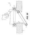
- a device 1 comprising a retractor member provided by a sleeve 2, a distal member provided by a distal ring 3 of resilient material such as an O-ring and a proximal member provided by a proximal ring 4 which may also be an O-ring.
- the sleeve 2 is of any suitable material such as of pliable plastics film material and comprises a distal portion 5 for insertion through an incision 6, in this case made in a patient's abdomen 7, and a proximal portion 8 for extending from the incision 6 and outside of the patient.
- the distal ring 3 is not fixed to the sleeve 2 but rather the sleeve is led around the ring 3 and is free to move axially relative to the distal ring 3 somewhat in the manner of a pulley.
- the proximal ring 4 is fixed to the sleeve 2, in this case at the proximal inner end thereof.
- the sleeve 2 terminates in a handle or gripping portion which in this case is reinforced by a gripping ring 15.
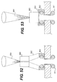
- a sleeve 2 is first provided with the gripping ring 15 fixed at one end and the proximal ring 4 fixed at the other end [ Figs. 3 , 5 ].
- the distal ring 3 is then placed over the sleeve 2 as illustrated in Figs. 4 and 6 .
- the gripping ring 15 is then used to manipulate the sleeve 2 so that the sleeve 2 is folded back on itself into the configuration of Figs. 1 and 2 in which the gripping ring 15 is uppermost.
- the sleeve extends from the proximal ring 4 and the distal ring 3 is contained between inner and outer layers 2a, 2b of the sleeve 2. The device is now ready for use.
- the resilient distal ring 3 is scrunched up and inserted through the incision 6 with the distal end 5 of the sleeve 2 as illustrated in Fig. 4 .
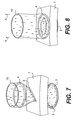
- the sleeve 2 is then pulled upwardly in the direction of the arrows A in Figs. 8 to 10 .
- the outer layer 2b is pulled up while the inner layer 2a is drawn around the proximal ring 3. This results in shortening the axial extent between the proximal ring 4 and the distal ring 3, tensioning the sleeve and applying a retraction force to the margins of the incision 6.
- the system appears to be self locking because when tension is applied to the sleeve 2 and the pulling force is released the rings 3, 4 remain in position with a retraction force applied. Frictional engagement between the layers of the sleeve in this configuration may contribute to this self locking.
- an access port is provided, for example for a surgeon to insert his hand and/or an instrument to perform a procedure.
- the device may be used as a retractor in open surgery or as a base for a valve/seal to allow it to be used in hand assisted laparoscopic surgery or for instrument or hand access generally.
- Excess sleeve portion 20 outside the incision may, for example, be cut-away.
- the retractor is suitable for a range of incision sizes and is easily manufactured. It is also relatively easy to manipulate, in use. It not only retracts but also protects the incision.
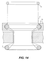
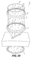
- the device comprises a guide member 51 for the proximal ring 4.
- the guide member 51 is in the form of an annular ring member with an inwardly facing C-shaped groove 52 which is sized to accommodate the ring 4 as illustrated.
- the outer layer of the sleeve 2 is interposed between the ring 4 and the guide 51 to further control the pulling of the sleeve and thereby further controlling the application of the retraction force.
- the guide 51 also assists in stabilising the proximal ring 4.
- the use of the device 50 is illustrated in Figs. 12 to 15 is similar to that described above.
- Any suitable guide such as the ring 51 may be used to assist in retaining/stabilising the proximal ring 4 in a desired position during pulling up of the sleeve to retract the incision.
- the guide may be located proximal of the ring 4.
- the guide member provides a monitoring member to which devices such as valves may be attached.
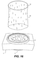
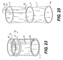
- the excess sleeve portion is inverted 60 into the incision.
- it may act as an organ retractor, or provide the surgeon with an open tunnel to work in.
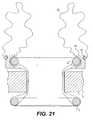
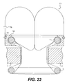
- a device 70 according to the invention has an integral seal/valve 71.
- the device 70 is similar to that described above with reference to Figs. 11 to 19 and like parts are assigned the same reference numerals.
- the guide member 50 has an outer groove 75 to receive the gripping ring 15 as illustrated in Figs. 21 .
- the excess sleeve portion 20 is folded out and down and the gripping ring 15 is engaged in the groove 75 to provide an air tight seal.
- the excess sleeve may be inflated through an inflation port 76 [ Fig. 22 ] to provide an integral access valve 71.
- the valve may be used to sealingly engage a hand, instrument or the like passing therethrough.
- the inflated sleeve portion defining the valve is evertable on passing an object therethrough.
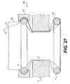
- the retractor 80 has a release mechanism which in this case is provided by a release cord or ribbon 81 which is coupled at one end 82 to the inner ring 3 and terminates in an outer free end 83 which may be grasped by a user.
- the ribbon 81 on assembly, is led through the gap between the proximal ring 4 and the outer guide member 51 so that it is positioned between the ring 4 and the guide member.
- the ribbon 81 facilitates release of the self locked sleeve in the in-use configuration sited in an incision. Pulling on the ribbon 81 pulls on the inner ring 3, allowing the ring 3 to be released from the inner wall of the incision to thereby release the device.
- the flexibility of the ring 3 facilitates this movement.
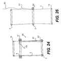
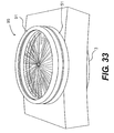
- the device 90 has a lower guide ring 51 for the proximal ring 4 and an outer guide assembly provided by an upper guide ring 91 and a second proximal ring 92 between which the sleeve 2 is led.
- the upper guide such as the ring 91 may provide a second mounting member located proximally of the first guide member such as the ring 51 which also provides a mounting member.
- the device is used to first retract an incision as described above.
- the outer guide assembly is conveniently external of the guide member 51 and proximal ring 4.
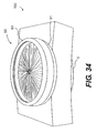
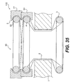
- FIGs. 34 and 35 there is illustrated another retractor device 100 according to the invention which is similar to the device of Figs. 29 to 33 and like parts are assigned the same reference numerals.
- a releasable lock is provided to maintain the access valve 95 closed.
- the upper guide ring 91 is an interference fit with the lower guide ring 51.
- Various other locking arrangements may be used such as a screw threaded or bayonet type engagement, magnets, clips and the like.
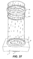
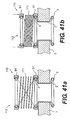
- FIG. 36 to 41 there is illustrated another retractor device 110 according to the invention which is similar to the device of Figs. 29 to 33 and like parts are assigned the same reference numerals.
- the device incorporates a biassing means to bias an integral valve into a closed position.
- the biassing means is in this case provided by a coil spring 111 which is located around the sleeve between the guide rings 51, 91.
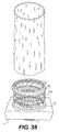
- the device is used in a similar manner to the device of Figs. 29 to 33 except that on movement of the upper guide ring 91 downwardly the spring 111 also moves downwardly towards the lower guide ring 51, initially into the position illustrated in Fig. 38 . Excess sleeve material may be removed at this stage.
- the spring 111 is tensioned as the upper ring 91 is rotated while pushing the upper ring 91 downwardly.
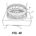
- the sleeve material between the two rings 51, 91 is twisted, forming an iris type valve 112 as illustrated in Fig. 39 .
- a downward force may be applied to push the upper ring 91 towards the lower ring 51 against the biassing of the spring.
- This configuration is illustrated in Fig. 40 .
- the upper ring member 91 is released, allowing the valve to close around the object.
- the operation of the device 110 will be readily apparent from Figs. 41(a) to 41(d) .
- Fig. 41(a) to 41(d) In Fig.
- valve 112 is illustrated in a closed resting configuration.
- Fig. 41(b) shows the application of a downward force to open the valve 112.
- An object such as an instrument 113 is shown inserted through the open valve 112 in Fig. 41(c) .
- Fig. 41(d) the downward pressure on the upper ring 91 is released allowing the valve 112 to close around the object 113.
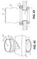
- Figs. 42 to 45 there is illustrated another device 120 according to the invention which has some aspects similar to the device of Figs. 11 to 18 and like parts are assigned the same reference numerals.
- the device has a lip seal 121.
- the lip seal 121 is provided by a membrane with a central aperture 122 through which an object 123 such as an instrument is passed.
- the lip seal 121 is located on the sleeve 2 proximally of the guide ring 51 such that a proximal flexible sleeve section 125 is provided. This sleeve section 125 is very useful in facilitating offset movements of the object 123 as illustrated in Fig. 45 .
- the sleeve section 125 accommodates movement of the object 123 whilst maintaining sealing engagement between the lip seal 121 and the object 123. It will be appreciated that this feature, as with several other features described above may be utilised in association with other constructions of wound protector/retractors and access parts generally other than those illustrated in the drawings.
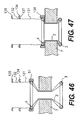
- Figs. 46 to 48 there is illustrated another device 130 according to the invention which has some features similar to those of Figs. 11 to 15 , like parts being assigned the same reference numerals.
- the sleeve has a proximal section external of the wound when the device is in the retracting configuration.
- This proximal sleeve section comprises a first portion 131 extending from the guide ring 51 and a second portion 132 extending from the first portion 131.
- the second portion 132 is defined between two spaced-apart iris rings 134, 135.
- the iris rings 134, 135 have engagement features such as projections and grooves for interengagement on assembly.
- the iris ring 134 also has an engagement element, in this case provided by a groove 137 for engagement on assembly with a corresponding engagement element of the guide ring 51 which in this case is provided by a projection 138.
- the device is fitted as described above to retract an incision, leaving the first and second sleeve portions 131, 132 extending proximally.
- the first sleeve portion 131 is redundant and can be removed or scrunched up on assembly of the first iris ring 134 to the guide ring 138 as illustrated in Fig. 48 .
- the second or upper iris ring 135 is then rotated to twist the sleeve section 132 to form an iris-type seal as illustrated in Fig. 49 .
- the iris ring 135 is engaged with the iris ring 134 as illustrated to maintain the valve closed.
- a valve 829 is mounted directly to a retractor base 811. It is possible to provide a flexible coupling between the retractor 811 and the valve 829. For example, as illustrated in Figs. 93 and 94 such a flexible coupling is provided by a length of flexible sleeve 830 extending between the retractor 811 and the valve 829.
- the flexible sleeve 830 may be formed by excess retractor sleeve material attached to the valve 829.
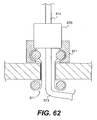
- a valve 860 may be coupled to the retractor 811 in such a way as to facilitate a flexible joint therebetween.
- a fixed length sleeve 862 may extend between an outer proximal ring 863 of the retractor 81 and the valve 860.
- Excess sleeve material 864 from the retractor 811 may pass up through the valve 860.
- the valve 860 may be pushed down and the excess sleeve pulled up to firmly lock the base retractor 811 in the incision.
- Excess sleeve material 864 may be cut-away and removed, if desired.
- the flexible sleeve 864 allows the instrument to tilt as illustrated in Fig. 57 without compromising the valve seal to the shaft of the instrument/object 814.
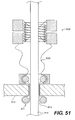
- a spring 867 may be provided between the valve 860 and the retractor proximal ring 863 for more controlled flexibility.
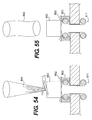
- a valve 870 is releasably mounted to a retractor 811.
- the retractor 811 may have a proximal ring 871 with a recess 872 to receive the valve 870.
- An instrument shaft 814 can readily pass through the valve 870 and retractor 811. At least a section 873 of the shaft 814 can be bent or steered almost immediately distal of the retractor.
- any suitable valve 880 may be coupled to a retractor 811 using excess sleeve material 881 from the retractor 811.
- the valve 880 may be pulled upwardly to deploy the base retractor 811.
- the excess sleeve material 881 provides a flexible neck which facilitates easy introduction of objects such as an instrument 883, even one having a bent shaft (Fig. 119).
- Fig. 120 such an arrangement also facilitates additional instrument reach by allowing the valve 880 to be moved closer to the base retractor 811.
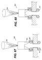
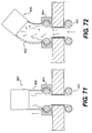
- FIG. 67 to 72 there is illustrated another access port comprising a wound protector and retractor device 811 and a valve 900.
- the valve 900 is connected to an outer guide ring 901 of the retractor device 811 by a sleeve 902 which in this case is of malleable material of corrugated configuration somewhat in the manner of the bendable hinge portion of a bendable drinking straw.
- the sleeve 902 may be pre-shaped to be offset from the longitudinal axis of the retractor to facilitate ease of insertion of an instrument or the like.
- the corrugated sleeve 902 may be compressed as illustrated in Fig. 68 to provide a low profile to facilitate outlining any of excess retractor sleeve as illustrated in Figs.
- the corrugated sleeve 902 can be extended / elongated and is readily manipulated into a desired configuration. Because the sleeve 902 is malleable it will retain a desired bent shape, even when the abdomen is pressurised. Any excess retractor sleeve material 905 may be cut-away as illustrated or used as described above.
- malleable is used to denote an element which is capable of being manipulated into a desired position and/or orientation, and which retains this manipulated position and/or orientation under the typical stresses and strains applied when used for an intended purpose with a patient, for example during partial insertion of a laparoscopic instrument.
- the access ports of the invention can be used in a number of ways.
- the retractor is used as described above, the distal inner ring being inserted into an incision, the outer ring being slid to controllably radially expand the incision. The retractor may then be locked in position. If necessary, the outer ring can be moved further downwardly to create a larger incision.
- an instrument may be bent manually outside the body and the bent instrument is delivered through the access port to readily access the operative site.
- an instrument is inserted into the access port and the surgeon uses the abdominal wall itself to bend the instrument and then insert the bent section further into the abdomen.
- the sleeve may be gripped by gripping a valve or other element mounted thereto.
Applications Claiming Priority (4)
| Application Number | Priority Date | Filing Date | Title |
|---|---|---|---|
| US41578002P | 2002-10-04 | 2002-10-04 | |
| US42821502P | 2002-11-22 | 2002-11-22 | |
| US49090903P | 2003-07-30 | 2003-07-30 | |
| EP03753883A EP1545348B1 (de) | 2002-10-04 | 2003-10-06 | Chirurgischer wundretraktor |
Related Parent Applications (1)
| Application Number | Title | Priority Date | Filing Date |
|---|---|---|---|
| EP03753883A Division EP1545348B1 (de) | 2002-10-04 | 2003-10-06 | Chirurgischer wundretraktor |
Publications (2)
| Publication Number | Publication Date |
|---|---|
| EP1987791A2 true EP1987791A2 (de) | 2008-11-05 |
| EP1987791A3 EP1987791A3 (de) | 2008-11-19 |
Family
ID=32074375
Family Applications (2)
| Application Number | Title | Priority Date | Filing Date |
|---|---|---|---|
| EP03753883A Expired - Lifetime EP1545348B1 (de) | 2002-10-04 | 2003-10-06 | Chirurgischer wundretraktor |
| EP08011478A Withdrawn EP1987791A3 (de) | 2002-10-04 | 2003-10-06 | Wundspreizer |
Family Applications Before (1)
| Application Number | Title | Priority Date | Filing Date |
|---|---|---|---|
| EP03753883A Expired - Lifetime EP1545348B1 (de) | 2002-10-04 | 2003-10-06 | Chirurgischer wundretraktor |
Country Status (9)
| Country | Link |
|---|---|
| EP (2) | EP1545348B1 (de) |
| JP (2) | JP4505643B2 (de) |
| AT (1) | ATE400226T1 (de) |
| AU (1) | AU2003272042A1 (de) |
| BR (1) | BR0315045A (de) |
| CA (1) | CA2499835A1 (de) |
| DE (1) | DE60322083D1 (de) |
| MX (1) | MXPA05003554A (de) |
| WO (1) | WO2004030547A1 (de) |
Cited By (1)
| Publication number | Priority date | Publication date | Assignee | Title |
|---|---|---|---|---|
| US9521996B2 (en) | 2011-07-13 | 2016-12-20 | Cook Medical Technologies Llc | Surgical retractor device |
Families Citing this family (49)
| Publication number | Priority date | Publication date | Assignee | Title |
|---|---|---|---|---|
| US7537564B2 (en) | 1998-12-01 | 2009-05-26 | Atropos Limited | Wound retractor device |
| US7559893B2 (en) | 1998-12-01 | 2009-07-14 | Atropos Limited | Wound retractor device |
| CN1169493C (zh) | 1999-10-14 | 2004-10-06 | 阿特波斯有限公司 | 创口牵引器 |
| US8021296B2 (en) | 1999-12-01 | 2011-09-20 | Atropos Limited | Wound retractor |
| EP1326524B1 (de) | 2000-10-19 | 2010-09-01 | Applied Medical Resources Corporation | Chirurgisches zugangsgerät und -verfahren |
| EP1416981B1 (de) | 2001-08-14 | 2013-07-24 | Applied Medical Resources Corporation | Gerät zum Verschliessen von Zugängen |
| US20050033246A1 (en) | 2002-05-14 | 2005-02-10 | Ahlberg Russell E. | Surgical device with tack-free gel and method of manufacture |
| JP4527528B2 (ja) | 2002-06-05 | 2010-08-18 | アプライド メディカル リソーシーズ コーポレイション | 創傷開創器 |
| US9271753B2 (en) | 2002-08-08 | 2016-03-01 | Atropos Limited | Surgical device |
| ES2287516T3 (es) | 2002-09-19 | 2007-12-16 | Atropos Limited | Sistema retractor de herida. |
| US20050020884A1 (en) | 2003-02-25 | 2005-01-27 | Hart Charles C. | Surgical access system |
| US7425202B2 (en) * | 2004-03-05 | 2008-09-16 | Percutaneous Systems, Inc. | Non-seeding biopsy device and method |
| EP2260777A1 (de) | 2004-10-11 | 2010-12-15 | Atropos Limited | Instrumentenzugriffsvorrichtung |
| JP5239029B2 (ja) | 2005-02-04 | 2013-07-17 | アトロポス・リミテッド | 外科用器具を少なくとも部分的に創傷開口を通して挿入するための装置 |
| EP1861022A2 (de) * | 2005-03-22 | 2007-12-05 | Atropos Limited | Operationsinstrument |
| WO2007047332A1 (en) | 2005-10-14 | 2007-04-26 | Applied Medical Resources Corporation | Split hoop wound retractor with gel pad |
| US8231527B2 (en) | 2006-07-18 | 2012-07-31 | Ethicon Endo-Surgery, Inc. | Roll-up wound protector with asymmetric ring |
| US7749161B2 (en) | 2006-12-01 | 2010-07-06 | Ethicon Endo-Surgery, Inc. | Hand assisted laparoscopic device |
| US7922656B2 (en) | 2007-04-04 | 2011-04-12 | Ethicon Endo-Surgery, Inc. | Hand assisted laparoscopic seal assembly with detachable attachment ring |
| CA2682923C (en) | 2007-05-11 | 2014-10-07 | Applied Medical Resources Corporation | Surgical retractor with gel pad |
| US8187178B2 (en) | 2007-06-05 | 2012-05-29 | Atropos Limited | Instrument access device |
| US20110071359A1 (en) | 2007-06-05 | 2011-03-24 | Frank Bonadio | Instrument Access Device |
| US8657740B2 (en) | 2007-06-05 | 2014-02-25 | Atropos Limited | Instrument access device |
| US8465515B2 (en) | 2007-08-29 | 2013-06-18 | Ethicon Endo-Surgery, Inc. | Tissue retractors |
| US8142354B1 (en) | 2007-10-30 | 2012-03-27 | Ethicon Endo-Surgery, Inc. | Laminated surgical access port |
| US8273017B1 (en) | 2007-10-30 | 2012-09-25 | Ethicon Endo-Surgery, Inc. | Surgical access port with ring actuated latching mechanism |
| US8128559B2 (en) | 2007-11-26 | 2012-03-06 | Ethicon Endo-Surgery, Inc. | Tissue retractors |
| US8517931B2 (en) | 2007-11-26 | 2013-08-27 | Ethicon Endo-Surgery, Inc. | Tissue retractors |
| WO2010045253A1 (en) | 2008-10-13 | 2010-04-22 | Applied Medical Resources Corporation | Single port access system |
| US8147405B2 (en) | 2008-10-30 | 2012-04-03 | Ethicon Endo-Surgery, Inc. | Surgical access port with multilayered tortuous path seal |
| US8375955B2 (en) | 2009-02-06 | 2013-02-19 | Atropos Limited | Surgical procedure |
| US8257251B2 (en) | 2009-04-08 | 2012-09-04 | Ethicon Endo-Surgery, Inc. | Methods and devices for providing access into a body cavity |
| US8926504B2 (en) * | 2010-10-01 | 2015-01-06 | Covidien Lp | Access assembly |
| CA2811753C (en) | 2010-10-01 | 2019-05-21 | Applied Medical Resources Corporation | Natural orifice surgery system |
| US9289115B2 (en) | 2010-10-01 | 2016-03-22 | Applied Medical Resources Corporation | Natural orifice surgery system |
| US8668641B2 (en) * | 2011-03-30 | 2014-03-11 | Covidien, LP | Surgical access assembly with sleeve and adjustable fastener |
| JP6005143B2 (ja) | 2011-05-10 | 2016-10-12 | アプライド メディカル リソーシーズ コーポレイション | 開創器 |
| US20130225932A1 (en) * | 2012-02-23 | 2013-08-29 | Covidien Lp | Multi-portion wound protector |
| US9320861B2 (en) | 2013-02-21 | 2016-04-26 | Covidien Lp | Smoke vent for access port device |
| KR102300866B1 (ko) | 2013-03-15 | 2021-09-13 | 어플라이드 메디컬 리소시스 코포레이션 | 기계적인 겔 수술 액세스 디바이스 |
| KR102196662B1 (ko) | 2013-03-15 | 2020-12-30 | 어플라이드 메디컬 리소시스 코포레이션 | 투관침 수술용 시일 |
| US9775591B2 (en) * | 2013-11-21 | 2017-10-03 | Edwards Lifesciences Corporation | Sealing devices and related delivery apparatuses |
| EP3169510B1 (de) | 2014-07-18 | 2018-10-03 | Applied Medical Resources Corporation | Verfahren zur herstellung von gelen mit permanenten, nichtklebenden beschichtungen |
| EP4101405A1 (de) | 2014-08-15 | 2022-12-14 | Applied Medical Resources Corporation | Chirurgisches system für natürliche öffnung |
| JP2017535399A (ja) | 2014-11-25 | 2017-11-30 | アプライド メディカル リソーシーズ コーポレイション | 支持および案内構造を備えた周囲創部レトラクション |
| KR102632231B1 (ko) | 2015-04-23 | 2024-02-01 | 어플라이드 메디컬 리소시스 코포레이션 | 조직 제거를 위한 시스템들 및 방법들 |
| ES2937400T3 (es) | 2015-09-15 | 2023-03-28 | Applied Med Resources | Sistema de acceso robótico quirúrgico |
| KR20180066157A (ko) | 2015-10-07 | 2018-06-18 | 어플라이드 메디컬 리소시스 코포레이션 | 멀티-세그먼트 바깥쪽 링을 갖는 상처 견인기 |
| CA3036192A1 (en) | 2016-09-12 | 2018-03-15 | Applied Medical Resources Corporation | Surgical robotic access system for irregularly shaped robotic actuators and associated robotic surgical instruments |
Family Cites Families (9)
| Publication number | Priority date | Publication date | Assignee | Title |
|---|---|---|---|---|
| US5514133A (en) * | 1994-08-26 | 1996-05-07 | Golub; Robert | Access device for endoscopic surgery |
| US5906577A (en) * | 1997-04-30 | 1999-05-25 | University Of Massachusetts | Device, surgical access port, and method of retracting an incision into an opening and providing a channel through the incision |
| US6440063B1 (en) * | 1997-04-30 | 2002-08-27 | University Of Massachusetts | Surgical access port and laparoscopic surgical method |
| EP1146826B1 (de) * | 1998-12-01 | 2005-11-02 | Atropos Limited | Chirurgische vorrichtung zurretraktion und/oder zum verschliessen eines einstiches |
| DE69920744T2 (de) * | 1998-12-01 | 2005-10-13 | Atropos Ltd., Bray | Laparoskopische abgedichtete zugangsvorrichtung |
| JP2001340346A (ja) * | 1999-06-08 | 2001-12-11 | Sumitomo Bakelite Co Ltd | 医療用処置用具 |
| US6171282B1 (en) * | 1999-07-23 | 2001-01-09 | Edgar K. Ragsdale | Soft cannula and methods for use |
| IE990795A1 (en) * | 1999-07-30 | 2001-03-07 | Gaya Ltd | Hand Access Port Device |
| CN1169493C (zh) * | 1999-10-14 | 2004-10-06 | 阿特波斯有限公司 | 创口牵引器 |
-
2003
- 2003-10-06 AU AU2003272042A patent/AU2003272042A1/en not_active Abandoned
- 2003-10-06 CA CA002499835A patent/CA2499835A1/en not_active Abandoned
- 2003-10-06 EP EP03753883A patent/EP1545348B1/de not_active Expired - Lifetime
- 2003-10-06 AT AT03753883T patent/ATE400226T1/de not_active IP Right Cessation
- 2003-10-06 EP EP08011478A patent/EP1987791A3/de not_active Withdrawn
- 2003-10-06 WO PCT/IE2003/000141 patent/WO2004030547A1/en active IP Right Grant
- 2003-10-06 BR BR0315045-3A patent/BR0315045A/pt not_active IP Right Cessation
- 2003-10-06 MX MXPA05003554A patent/MXPA05003554A/es active IP Right Grant
- 2003-10-06 DE DE60322083T patent/DE60322083D1/de not_active Expired - Lifetime
- 2003-10-06 JP JP2005500081A patent/JP4505643B2/ja not_active Expired - Fee Related
-
2009
- 2009-11-26 JP JP2009269354A patent/JP2010069316A/ja active Pending
Non-Patent Citations (1)
| Title |
|---|
| None * |
Cited By (1)
| Publication number | Priority date | Publication date | Assignee | Title |
|---|---|---|---|---|
| US9521996B2 (en) | 2011-07-13 | 2016-12-20 | Cook Medical Technologies Llc | Surgical retractor device |
Also Published As
| Publication number | Publication date |
|---|---|
| AU2003272042A1 (en) | 2004-04-23 |
| EP1545348A1 (de) | 2005-06-29 |
| JP2010069316A (ja) | 2010-04-02 |
| CA2499835A1 (en) | 2004-04-15 |
| JP4505643B2 (ja) | 2010-07-21 |
| EP1545348B1 (de) | 2008-07-09 |
| WO2004030547A1 (en) | 2004-04-15 |
| DE60322083D1 (de) | 2008-08-21 |
| MXPA05003554A (es) | 2005-09-30 |
| BR0315045A (pt) | 2005-08-23 |
| JP2006501973A (ja) | 2006-01-19 |
| ATE400226T1 (de) | 2008-07-15 |
| EP1987791A3 (de) | 2008-11-19 |
Similar Documents
| Publication | Publication Date | Title |
|---|---|---|
| US10278688B2 (en) | Wound retractor device | |
| EP1545348B1 (de) | Chirurgischer wundretraktor | |
| US9307976B2 (en) | Wound retractor | |
| US20050192483A1 (en) | Device | |
| US9277908B2 (en) | Retractor | |
| EP1572014B1 (de) | Chirurgische vorrichtung | |
| US7540839B2 (en) | Wound retractor | |
| EP1610696B1 (de) | Chirurgischer wundretraktor | |
| EP1125552A1 (de) | Chirurgischer Retraktor | |
| IE20030737A1 (en) | A wound retractor device | |
| IE20060520A1 (en) | A wound retractor | |
| IE20040521A1 (en) | A cannula | |
| IE20030945A1 (en) | A surgical access device |
Legal Events
| Date | Code | Title | Description |
|---|---|---|---|
| PUAI | Public reference made under article 153(3) epc to a published international application that has entered the european phase |
Free format text: ORIGINAL CODE: 0009012 |
|
| PUAL | Search report despatched |
Free format text: ORIGINAL CODE: 0009013 |
|
| 17P | Request for examination filed |
Effective date: 20080625 |
|
| AC | Divisional application: reference to earlier application |
Ref document number: 1545348 Country of ref document: EP Kind code of ref document: P |
|
| AK | Designated contracting states |
Kind code of ref document: A2 Designated state(s): AT BE BG CH CY CZ DE DK EE ES FI FR GB GR HU IE IT LI LU MC NL PT RO SE SI SK TR |
|
| AK | Designated contracting states |
Kind code of ref document: A3 Designated state(s): AT BE BG CH CY CZ DE DK EE ES FI FR GB GR HU IE IT LI LU MC NL PT RO SE SI SK TR |
|
| RIN1 | Information on inventor provided before grant (corrected) |
Inventor name: REID, ALAN Inventor name: BUTLER, JOHN Inventor name: BONADIO, FRANK Inventor name: VAUGH, TREVOR Inventor name: MCNALLY, SHANE JOSEPH |
|
| 17Q | First examination report despatched |
Effective date: 20090112 |
|
| AKX | Designation fees paid |
Designated state(s): AT BE BG CH CY CZ DE DK EE ES FI FR GB GR HU IE IT LI LU MC NL PT RO SE SI SK TR |
|
| GRAP | Despatch of communication of intention to grant a patent |
Free format text: ORIGINAL CODE: EPIDOSNIGR1 |
|
| INTG | Intention to grant announced |
Effective date: 20180601 |
|
| STAA | Information on the status of an ep patent application or granted ep patent |
Free format text: STATUS: THE APPLICATION IS DEEMED TO BE WITHDRAWN |
|
| 18D | Application deemed to be withdrawn |
Effective date: 20181012 |