EP1987201B1 - Railway rail pad - Google Patents
Railway rail pad Download PDFInfo
- Publication number
- EP1987201B1 EP1987201B1 EP07705239.7A EP07705239A EP1987201B1 EP 1987201 B1 EP1987201 B1 EP 1987201B1 EP 07705239 A EP07705239 A EP 07705239A EP 1987201 B1 EP1987201 B1 EP 1987201B1
- Authority
- EP
- European Patent Office
- Prior art keywords
- rail
- clip
- pad
- portions
- seat portion
- Prior art date
- Legal status (The legal status is an assumption and is not a legal conclusion. Google has not performed a legal analysis and makes no representation as to the accuracy of the status listed.)
- Not-in-force
Links
Images


Classifications
-
- E—FIXED CONSTRUCTIONS
- E01—CONSTRUCTION OF ROADS, RAILWAYS, OR BRIDGES
- E01B—PERMANENT WAY; PERMANENT-WAY TOOLS; MACHINES FOR MAKING RAILWAYS OF ALL KINDS
- E01B9/00—Fastening rails on sleepers, or the like
- E01B9/02—Fastening rails, tie-plates, or chairs directly on sleepers or foundations; Means therefor
- E01B9/28—Fastening on wooden or concrete sleepers or on masonry with clamp members
- E01B9/30—Fastening on wooden or concrete sleepers or on masonry with clamp members by resilient steel clips
- E01B9/303—Fastening on wooden or concrete sleepers or on masonry with clamp members by resilient steel clips the clip being a shaped bar
-
- B—PERFORMING OPERATIONS; TRANSPORTING
- B28—WORKING CEMENT, CLAY, OR STONE
- B28B—SHAPING CLAY OR OTHER CERAMIC COMPOSITIONS; SHAPING SLAG; SHAPING MIXTURES CONTAINING CEMENTITIOUS MATERIAL, e.g. PLASTER
- B28B23/00—Arrangements specially adapted for the production of shaped articles with elements wholly or partly embedded in the moulding material; Production of reinforced objects
- B28B23/0056—Means for inserting the elements into the mould or supporting them in the mould
-
- E—FIXED CONSTRUCTIONS
- E01—CONSTRUCTION OF ROADS, RAILWAYS, OR BRIDGES
- E01B—PERMANENT WAY; PERMANENT-WAY TOOLS; MACHINES FOR MAKING RAILWAYS OF ALL KINDS
- E01B3/00—Transverse or longitudinal sleepers; Other means resting directly on the ballastway for supporting rails
- E01B3/28—Transverse or longitudinal sleepers; Other means resting directly on the ballastway for supporting rails made from concrete or from natural or artificial stone
-
- E—FIXED CONSTRUCTIONS
- E01—CONSTRUCTION OF ROADS, RAILWAYS, OR BRIDGES
- E01B—PERMANENT WAY; PERMANENT-WAY TOOLS; MACHINES FOR MAKING RAILWAYS OF ALL KINDS
- E01B9/00—Fastening rails on sleepers, or the like
- E01B9/02—Fastening rails, tie-plates, or chairs directly on sleepers or foundations; Means therefor
- E01B9/28—Fastening on wooden or concrete sleepers or on masonry with clamp members
-
- E—FIXED CONSTRUCTIONS
- E01—CONSTRUCTION OF ROADS, RAILWAYS, OR BRIDGES
- E01B—PERMANENT WAY; PERMANENT-WAY TOOLS; MACHINES FOR MAKING RAILWAYS OF ALL KINDS
- E01B9/00—Fastening rails on sleepers, or the like
- E01B9/68—Pads or the like, e.g. of wood, rubber, placed under the rail, tie-plate, or chair
- E01B9/685—Pads or the like, e.g. of wood, rubber, placed under the rail, tie-plate, or chair characterised by their shape
- E01B9/686—Pads or the like, e.g. of wood, rubber, placed under the rail, tie-plate, or chair characterised by their shape with textured surface
-
- E—FIXED CONSTRUCTIONS
- E01—CONSTRUCTION OF ROADS, RAILWAYS, OR BRIDGES
- E01B—PERMANENT WAY; PERMANENT-WAY TOOLS; MACHINES FOR MAKING RAILWAYS OF ALL KINDS
- E01B2205/00—Electrical insulation of railway track parts
Abstract
Description
- The present invention relates to a railway rail pad.
- In the documents
WO93/12294 WO93/12295 WO93/12296 - Rail fastening assemblies as described in the applicant's patent applications
WO93/12294 WO93/12295 WO93/12296 - According to a first aspect of the present invention there is provided a rail pad for use beneath a railway rail in a rail fastening assembly as cushioning and/or electrical insulation, the pad having a major face providing a rail seat portion on which the foot of the railway rail sits when the rail pad is in use, and further comprising two upstanding portions, integrally formed with the said rail seat portion along opposite edges thereof, so as to extend along only a central part of the edge; characterised in that the pad is suitable for use with resilient rail fastening clips which are configured to be driven onto and off the rail foot, above the upstanding portions, in a lateral direction with respect to the longitudinal axis of the rail.
- Rail pads with upstanding portions are known from
GB2106570A GB2235003A - The upstanding portions are preferably made of electrically-insulating material and are shaped and arranged so as to form insulation members for electrically insulating the rail foot from rail clip anchoring devices located one on either side of the rail when the pad is in use.
- By forming the pad and side post insulators as one part, rather than two separate insulators and a pad, the unit can be produced more cheaply that the three separate parts. Because it is one part, it is also easier to fit than three separate parts - both in the sleeper factory and in the field. In addition, because the sidepost insulator members and rail seat portion are formed as one part, the rail pad will contribute to good overall electrical resistance of the assembly. In particular, by making a good seal between the insulator members and the rail seat portion, electrical insulation can be improved, as compared to having separate pad and insulator parts, because there is no path for moisture to be drawn through.
- Desirably, the insulation members are formed of a material having greater resilience to damage than the rail seat portion of the pad, since these portions are subject to much higher pressure than the rail seat portion, due to the lateral loads which are transmitted through them to the shoulder. For example, the insulation members may be made of nylon and the rail seat portion of EVA.
- It will, however, probably be necessary to replace worn sidepost insulators in track before the rail seat portion is due for replacement and accordingly, in order to avoid having to unclip the rail and jack the rail up in order to remove the rail pad, the upstanding portions are preferably attached to the rail seat portion in such a manner as to be readily detachable therefrom. The upstanding portions desirably mechanically interlock with the said rail seat portion.
- Thus, in this preferred embodiment of the pad, the pad is such that the side post elements can be torn away from the rail seat portion after the pad is installed in track, thereby eliminating the need to jack the rail and the cost of replacing the rail seat portion of the pad. The new replacement parts would be separate individual side post insulators, that would not need to connect to the rail seat portion of the pad. It would not be a problem if one or both of the insulator members became detached from the rail seat portion in service, through wear or mechanical action rather than through deliberate action, as once in place the rail seat portion and insulating members of the pad can function separately, as in the prior art.
- In use, the load has to go straight through the insulators into the shoulder, so the insulators must be hard up against the shoulders with no clearance. However, the actual positions of the shoulders will vary due to the tolerance on sleeper manufacture and it is obviously undesirable to provide a number of rail pads of different widths. Accordingly, in a preferred embodiment of the pad, the width of the said rail seat portion can conform to a range of rail seat widths. Preferably, this is achieved by providing the rail seat region of the pad with a concertinaed section which can be stretched or squeezed between a minimum width and a maximum width, so as to adjust the overall width of the rail seat portion. Thus, the pad is sized to fit a maximum railseat, and would be a 'squash fit' into a narrower railseat.
- According to a second aspect of the present invention there is provided a railway rail fastening assembly comprising two railway rail fastening clips, two anchoring devices for retaining respective ones of the rail fastening clips when installed therein and a rail pad embodying the first aspect of the present invention, located between the two anchoring devices, wherein each insulation member of the pad is formed with a shelf which extends over a portion of that anchoring device.which is adjacent thereto, the shelf being overlain by the rail clip installed in the anchoring device when the clip is in a pre-assembly position in which the clip does not overlie the rail seat portion of the pad. Thus, the pad is held in place by the clip.
- Reference will now be made, by way of example, to the accompanying drawings in which:
-
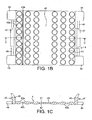
Figure 1 shows a rail pad embodying the first aspect of the present invention, in whichFigure 1A is a perspective view from above,Figure 1B is a plan view from above andFigure 1C is a cross-sectional view taken along the line C-C inFigure 1B . -
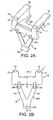
Figure 2 shows an anchoring device for use with a rail pad embodying the first aspect of the present invention,Figure 2A showing a perspective view from above,Figure 2B showing a front view,Figure 2C showing a part sectional view taken on the line Z-Z inFigure 2B ,Figure 2D showing a rear view,Figure 2E showing a side view,Figure 2F showing a plan view from above,Figure 2G showing a plan view from below andFigure 2H showing a side view of another anchoring device embodying the first to fourth aspects of the present invention; -
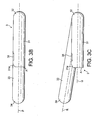
Figure 3 shows a railway rail fastening clip for use with a rail pad embodying the first aspect of the present invention,Figure 3A showing a plan view of the clip,Figure 3B showing a side view of the clip when in its non-operative configuration andFigure 3C showing a side view of the clip when in an operative configuration; and -
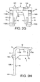
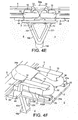
Figure 4 shows a railway rail fastening assembly embodying the second aspect of the present invention, in whichFigures 4A and 4B show the assembly in a side view in which the clip is in a pre-assembly position with respect to the rail,Figure 4B being a part cross-sectional view,Figures 4C and 4D show another side view of the assembly in which the clip is bearing on the rail,Figure 4D being a part cross-sectional view,Figure 4E shows a rear view of the assembly andFigure 4F shows a perspective view of the assembly. - A studded
rail pad 4 embodying the first aspect of the present invention will now be described with reference toFigures 1A to 1C .Rail pad 4 is made of electrically-insulating material and is substantially rectangular in outline, having a firstmajor face 41 and a secondmajor face 42 opposite to the first major face, the firstmajor face 41 providing arail seat portion 43 on which rows ofstuds 43a are provided, therail seat portion 43 providing cushioning between the underside of the rail foot and the underlying concrete sleeper. Therail seat portion 43 is also provided with aconcertinaed section 43b which extends across therail seat portion 43 in a direction parallel to the axis of a rail when seated thereon, the concertinaed section serving to allow the pad to conform to rail seats of varying widths, within a certain range. The four corners of the rail pad constituteears 44 between which there are defined tworecesses 45 which receiverespective shoulders 1, providing longitudinal location and creep resistance. Integrally formed with therail seat portion 43 and theears 44 aresidepost insulator portions 46 for insulating the rail from theshoulder 1, each insulatingportion 46 projecting upwardly from the firstmajor face 41 and having a substantiallyhorizontal shelf 47 which extends away from therail seat portion 43 such that, when therail pad 4 is in position between twoshoulders 1, theshelf 47 will extend over a portion of theshoulder 1 and will be overlain by thetoe portion 34 of aclip 3 installed in theshoulder 1. - To minimize part cost and manufacturing time, the
sidepost insulator portions 46, which may be formed of nylon, may be cored out, the cored-out parts of theinsulator portions 46 being filled with the material forming therail seat portion 43, for example EVA. - With reference to
Figures 2A to 2G an anchoring device (shoulder) for use with a rail pad embodying the invention will now be described. Theanchoring device 1 shown inFigures 2A to 2G comprises ahead 1A from the underside of which downwardly project astem part 1B and two spaced-part tangs 1C. Thestem part 1B comprises a substantially Y-shaped stem 100, connected to the underside of thehead 1A at the ends ofupper arms 101 of the Y, and abent part 102 at the other end of the Y for resisting withdrawal of the stem from the concrete in which it is embedded when it is in use. As shown inFig. 2H , which shows another shoulder for use with a rail pad embodying the present invention, the underside of theshoulder 1 may be provided with one ormore webs 1D connecting thestem 100 of theshoulder 1 to itshead 1A, instead or in addition to thetangs 1C (not shown inFig. 2H ), for assisting in preventing theshoulder 1 tipping forward when a clip is driven into it. - The
head 1A of theanchoring device 1 comprises two spaced-part walls 10, connected together at one end of thehead 1A, at the bottom of thewalls 10, by aconnection portion 14. The top surface of theconnection portion 14 is downwardly inclined and forms aramp 140, while the front surface of theconnection portion 14 forms thefront face 12 of theshoulder 1. The end of thewalls 10 at the front end of thehead 1A are connected to thefront face 12 of the shoulder bycurved portions 13. - The
walls 10 extend outwardly at their tops to provide respective clip-engaging surfaces 11 provided with two clip-engaging projections surface 111 which inclines downwardly from the rear of theshoulder 1 to the front of theshoulder 1, for deflecting the leg of a railway rail fastening clip. Thefront face 12 of theshoulder 1 is provided withprojections 120 for engaging with the sleeper mould so as to set the shoulder at the correct height in the mould before the concrete is introduced. Theshoulder 1 has arear face 15 opposite to thefront face 12. - A railway
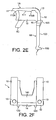
rail fastening clip 3 for use with a rail pad embodying the first aspect of the present invention will now be described with reference toFigures 3A to 3C . Therail clip 3 is formed from a steel rod bent so as to have, proceeding from one end A of the rod to the other end B of the rod, firstly a straightfirst portion 31 forming one leg of the clip, then a bentsecond portion 32 which bends through more than 180°, then athird portion 33, then afourth portion 34 which forms the toe portion of the clip and is bent through 180°, then afifth portion 35 which mirrors the shape of thethird portion 33, then asixth portion 36 which mirrors the shape of thesecond portion 32 and finally aseventh portion 37 which forms the other leg of the clip. Thus, when viewed as seen inFig. 3A , the clip may be considered to be substantially M-shaped. The free ends A, B, of the rod have achamfer 37a on the surface of the leg which is to be uppermost when theclip 3 is bearing on a rail for assisting in inserting the clip into the shoulder. Adjacent to the ends A, B, on the uppermost surface of theclip 3, theclip 3 is formed withdetents 38 for cooperating with theprojections walls 10 of theshoulder 1 to retain theclip 3. Thedetents 38 are formed so as to have two oppositely-inclined spaced-apart faces defining respective pre-assembly and insulator-change positions relative to theshoulder 1. - Although not shown in
Figures 3A to 3C , but seen fromFigures 4A to 4F , thetoe portion 34 of theclip 3 when in use normally carries atoe insulator 34a for insulating theclip 3 from the rail. Thetoe insulator 34a also extends over parts of the third and fifth portions, 33, 35 of theclip 3. In order to reduce the likelihood that thetoe insulator 34a may be removed unintentionally from theclip 3, those portions of thetoe portion 34 and third andfifth portions toe insulator 34a when it is located on theclip 3 may be left free of the coating which is generally applied to the remainder of the clip. - When the
clip 3 is in its non-operative configuration, i.e. a non-stressed configuration in which the clip is not in use, the longitudinal axes of all parts of the clip lie substantially in the same plane P, that is the clip is flat. - As shown in
Figure 3C , when theclip 3 is deflected into an operative configuration, by driving the clip into ashoulder 1, thelegs clip 3 are driven downwards out of the first plane P into a second plane Q and the third, fourth andfifth portions clip 3 are deflected upwardly out of the plane P into a third plane R, the planes P, Q, R being non-parallel. - Compared to the applicant's prior art switch-on/switch-off clip, the above-described clip may be made from 14mm diameter bar instead of 15mm. In addition, the clip is smaller in plan view, both shorter by about 10mm and narrower by about 10mm. The clip may be rolled around smaller radius formers to make the arches of the clip, in particular at the toe of the clip, as a consequence of which, and the smaller diameter, the clip may be significantly lighter. It also operates at a slightly higher stress level. The clip may be initially produced with some profile and then cold-set so that it returns to a flat shape (i.e. over-pressed when cold such that it yields and takes on some permanent deformation).
- A railway rail fastening assembly employing the elements described above will now be described with reference to
Figures 4A to 4F . The railway rail fastening assembly ofFigures 4A to 4F , for fastening arailway rail 5, comprises ashoulder 1, arail fastening clip 3, a sealingplate 2 and arail pad 4 embodying the first aspect of the present invention. It will be appreciated that, although not shown inFigures 4A to 4F , when in use the rail is fastened on both sides of the rail head by such an assembly and that thestem 1B and tangs 1C are embedded in theconcrete sleeper 6. The sealingplate 2 is also embedded in theconcrete sleeper 6, such that the top face of sealingplate 2 is flush with the upper surface of thesleeper 6. As shown inFigures 4A/4B theclip 3 may be driven into theshoulder 1 by introducing the chamfered free ends A, B of theclip legs top surfaces 25a of theclip seat projections 25 on the sealingplate 2 and thefirst projection 110A on the outer surface of thewalls 10 of theshoulder 1, and inserting thetoe portion 34 of theclip 3, bearing atoe insulator 34a, into the space between the inner surfaces of thewalls 10 of theshoulder 1, such that thetoe 34 of theclip 3, through thetoe insulator 34a, bears on theramp 140 of theshoulder 1 and theprojections 110A are located within thedetents 38 in theclip legs projection 110A contacting the rear face of thedetent 38. This position is known as the "pre-assembly" or "parked" position, in which the clip does not bear on therail 5, but overlies theshelf 47 of the sidepost insulator portion 46 ofpad 4. Downwardly-facing parts of thelegs top surfaces 25a of theclip seat projections 25. - As shown in
Figures 4C and 4D , theclip 3 can be driven from the pre-assembly position (first operative position) into a second operative position in which thetoe portion 34 of theclip 3 bears on the foot of therail 5, thesecond projections 110B on thewalls 10 engage thedetents 38 oflegs clip 3 and the second andsixth portions 32, 36 (heel portions) of theclip 3 bear on thetop surfaces 25a of theclip seat projections 25. The clip overlies theshelf 47 of the sidepost insulator portion 46 of therail pad 4. The clip can be withdrawn from this position back into the pre-assembly position, if required in order to remove or work on the rail, or further back into the "insulator-change" position in which the front face of thedetent 38 contacts theprojection 110A and theclip 3 does not overlie theshelf 47 of thesidepost insulator portion 46 ofpad 4. - As the
clip 3 is installed, thetoe 34 of theclip 3 is driven upwards by theramp 140 in the centre of theshoulder 1, and thelegs
Claims (12)
- A rail pad for use beneath a railway rail in a rail fastening assembly as cushioning and/or electrical insulation, the pad (4) having a major face (41) providing a rail seat portion (43) on which the foot of the railway rail sits when the rail pad (4) is in use, and further comprising two upstanding portions (46), integrally formed with the said rail seat portion (43) along opposite edges thereof, so as to extend along only a central part of the edge;
characterised in that the pad is suitable for use with resilient rail fastening clips which are configured to be driven onto and off the rail foot, above the upstanding portions (46), in a lateral direction with respect to the longitudinal axis of the rail. - A rail pad as claimed in claim 1, wherein the said upstanding portions (46) are made of electrically-insulating material and are shaped and arranged so as to form insulation members for electrically insulating the rail foot from rail clip anchoring devices (1) located one on either side of the rail when the pad (4) is in use.
- A rail pad as claimed in claim 2, wherein the insulation members (46) are formed of a material having greater resilience to damage than the rail seat portion (43) of the pad.
- A rail pad as claimed in claim 1, 2 or 3, wherein the upstanding portions (46) are attached to the rail seat portion (43) in such a manner as to be readily detachable therefrom.
- A rail pad as claimed in claim 4, wherein the said upstanding portions (46) mechanically interlock with the said rail seat portion (43).
- A rail pad as claimed in any preceding claim, wherein the width of the said rail seat portion (43) can conform to a range of rail seat widths.
- A rail pad as claimed in claim 6, wherein the rail seat portion (43) of the pad (4) has a concertinaed section (43b) which can be stretched or squeezed between a minimum width and a maximum width, so as to adjust the overall width of the rail seat portion (43).
- A railway rail fastening assembly comprising two railway rail fastening clips (3), two anchoring devices (1) for retaining respective ones of the rail fastening clips (3) when installed therein and a rail pad (4) as claimed in any preceding claim, located between the two anchoring devices (1), wherein each insulation member (46) of the pad (4) is formed with a shelf (47) which extends over a portion of that anchoring device (1) which is adjacent thereto, the shelf (47) being overlain by the rail clip (3) installed in the anchoring device (1) when the clip (3) is in a pre-assembly position in which the clip (3) does not overlie the rail seat portion (43) of the pad (4).
- An assembly as claimed in claim 8, wherein each of the clips (3) is such that it can be deflected from a non-operative configuration to at least one operative configuration in which a toe portion (34) of the clip (3) bears on a railway rail, the clip (3) being made from a rod of resilient material shaped so as to have, proceeding from one end A of the rod to the other end B of the rod, firstly a substantially straight first portion (31), then a substantially bent second portion (32), then a third portion (33), then a fourth portion (34) which is substantially U-shaped and forms the toe portion of the clip, then a fifth portion (35), then a substantially bent sixth portion (36), and finally a substantially straight seventh portion (37), the first and seventh portions (31, 37) of the clip (3) forming leg portions, the longitudinal axes of which lie substantially in a first plane (P) when the clip (3) is in its non-operative configuration and, when the clip (3) is viewed in a direction perpendicular to the said first plane (P), the third and fifth portions (33, 35) appear to lie between the first and seventh portions (31, 37), wherein, when the clip (3) is in its non-operative configuration, the longitudinal axes of the second, third, fourth, fifth and sixth portions (32 to 36) also lie substantially in the said first plane (P), and, when the clip (3) is in the said at least one operative configuration, the longitudinal axes of the third, fourth and fifth portions (33 to 35) lie substantially in a second plane (R) and the longitudinal axes of the first and seventh portions (31, 37) lie substantially in a third plane (Q), the second and third planes (R, Q) being non-parallel to one another.
- An assembly as claimed in claim 8 or 9, wherein each of the said anchoring devices (1) comprises two interconnected spaced-apart walls (10), between which a portion of the clip (3) to be retained is held when the anchoring device (1) is in use, and clip-engaging means (11), supported by the walls (10), for engaging a portion of the rail fastening clip (3) to be retained, wherein the device (1) does not have any feature or surface which engages the surface of that clip portion which faces downwardly when the clip (3) is in use.
- An assembly as claimed in claim 10, wherein the clip-engaging means (11) define contact regions (110A, 110B) at which the device (1) engages the rail clip (3) to be retained when the clip (3) bears on a railway rail, the device (1) not engaging the clip (3) at any other region of the device (1) when the clip (3) is bearing on the rail in normal operation, such that none of the said contact regions (110A, 110B) of the device can be seen when the anchoring device (1) is viewed from above when in its operative orientation in which it will be used when adjacent to a railway rail and all of the said contact regions (110A, 110B) of the device (1) can be seen when the anchoring device (1) is viewed from below when in the said operative orientation.
- An assembly as claimed in claim 11, wherein, when the device (1) is in use, all the said contact regions (110A, 110B) of the device (1) lie substantially at the same horizontal distance from the edge of the rail foot when measured perpendicularly to the axis of the rail and in the plane of the rail foot.
Applications Claiming Priority (2)
| Application Number | Priority Date | Filing Date | Title |
|---|---|---|---|
| GB0603434A GB2435285A (en) | 2006-02-21 | 2006-02-21 | Fastening railway rails |
| PCT/GB2007/000606 WO2007096616A1 (en) | 2006-02-21 | 2007-02-21 | Railway rail pad |
Publications (2)
| Publication Number | Publication Date |
|---|---|
| EP1987201A1 EP1987201A1 (en) | 2008-11-05 |
| EP1987201B1 true EP1987201B1 (en) | 2013-04-10 |
Family
ID=36178454
Family Applications (4)
| Application Number | Title | Priority Date | Filing Date |
|---|---|---|---|
| EP07705243.9A Active EP1987200B1 (en) | 2006-02-21 | 2007-02-21 | Sealing plate for railway rail clip anchoring device and sleeper manufacturing method |
| EP07705242A Active EP1987199B1 (en) | 2006-02-21 | 2007-02-21 | Railway rail fastening clip |
| EP07705239.7A Not-in-force EP1987201B1 (en) | 2006-02-21 | 2007-02-21 | Railway rail pad |
| EP07705236.3A Active EP1987198B1 (en) | 2006-02-21 | 2007-02-21 | Anchoring devices for rail fastening clips |
Family Applications Before (2)
| Application Number | Title | Priority Date | Filing Date |
|---|---|---|---|
| EP07705243.9A Active EP1987200B1 (en) | 2006-02-21 | 2007-02-21 | Sealing plate for railway rail clip anchoring device and sleeper manufacturing method |
| EP07705242A Active EP1987199B1 (en) | 2006-02-21 | 2007-02-21 | Railway rail fastening clip |
Family Applications After (1)
| Application Number | Title | Priority Date | Filing Date |
|---|---|---|---|
| EP07705236.3A Active EP1987198B1 (en) | 2006-02-21 | 2007-02-21 | Anchoring devices for rail fastening clips |
Country Status (26)
| Country | Link |
|---|---|
| US (4) | US20090261177A1 (en) |
| EP (4) | EP1987200B1 (en) |
| JP (3) | JP5172711B2 (en) |
| KR (5) | KR20080094737A (en) |
| CN (5) | CN101389811B (en) |
| AT (1) | ATE470756T1 (en) |
| AU (4) | AU2007217202B2 (en) |
| BR (4) | BRPI0706825B1 (en) |
| CA (4) | CA2642109C (en) |
| DE (1) | DE602007007060D1 (en) |
| DK (2) | DK1987200T3 (en) |
| EG (3) | EG25258A (en) |
| ES (3) | ES2441265T3 (en) |
| GB (1) | GB2435285A (en) |
| HK (4) | HK1122080A1 (en) |
| MX (1) | MX2008010679A (en) |
| MY (2) | MY150943A (en) |
| NO (2) | NO341359B1 (en) |
| NZ (1) | NZ570291A (en) |
| PL (2) | PL1987199T3 (en) |
| PT (1) | PT1987200E (en) |
| RU (1) | RU2434986C2 (en) |
| SI (1) | SI1987200T1 (en) |
| UA (1) | UA99435C2 (en) |
| WO (4) | WO2007096621A1 (en) |
| ZA (4) | ZA200806905B (en) |
Families Citing this family (39)
| Publication number | Priority date | Publication date | Assignee | Title |
|---|---|---|---|---|
| GB2435285A (en) * | 2006-02-21 | 2007-08-22 | Pandrol Ltd | Fastening railway rails |
| GB2450731B (en) * | 2007-07-04 | 2011-12-14 | Pandrol Ltd | Components for rail fastening assembly |
| GB2481338B (en) * | 2007-07-04 | 2012-02-15 | Pandrol Ltd | Sealing plate for use with rail clip anchoring device |
| BRPI0721678B1 (en) | 2007-07-04 | 2018-07-03 | Pandrol Limited | “Combination of one component and one rail rail clip anchor device, sealing plate, sleeper arrangement and rail fastening assembly” |
| US8042747B2 (en) * | 2007-08-31 | 2011-10-25 | Koppers Delaware, Inc. | Notched tie plate insulator |
| DE202007018566U1 (en) | 2007-09-14 | 2008-12-04 | Vossloh-Werke Gmbh | System for securing a rail on a level solid surface |
| GB2453575B (en) | 2007-10-11 | 2011-11-30 | Pandrol Ltd | Railway rail paid |
| MX2010001662A (en) * | 2009-02-11 | 2010-09-27 | Vossloh Werke Gmbh | Guide plate for a system for mounting a rail on a base, and a system comprising such a guide plate. |
| GB2472851B (en) * | 2009-08-21 | 2016-01-13 | Pandrol Ltd | Insulator for railway rail fastening clip |
| GB2472850B (en) * | 2009-08-21 | 2016-06-01 | Pandrol Ltd | Railway rail pad |
| DE102009041833B4 (en) * | 2009-09-18 | 2011-06-22 | Vossloh-Werke GmbH, 58791 | Shim for fixing a rail to a solid surface and fixing a rail |
| GB2476460B (en) * | 2009-12-22 | 2016-01-13 | Pandrol Ltd | Railway rail fastening apparatus |
| US8210444B2 (en) * | 2010-10-18 | 2012-07-03 | Osler Wilbur F | Direct fixation track-mounting assembly |
| CN102061645B (en) * | 2010-11-17 | 2012-10-03 | 中国铁道科学研究院铁道建筑研究所 | Steel rail buckling and pressing device |
| GB2500408B (en) * | 2012-03-21 | 2015-10-07 | Pandrol Ltd | Apparatus for use in concrete sleeper manufacture |
| PT2672007E (en) * | 2012-06-04 | 2015-11-26 | Vossloh Werke Gmbh | Guide plate for fixing rails for rail vehicles |
| GB2502990B (en) | 2012-06-12 | 2018-01-31 | Pandrol Ltd | Railway rail fastening clip for recessed railseats |
| DE102012014500A1 (en) * | 2012-07-23 | 2014-01-23 | Schwihag Ag | Rail fastening system for transition areas |
| EP2890850B1 (en) * | 2012-08-31 | 2017-11-01 | Pandrol Australia Pty Ltd | Anchoring devices for rail fastening clips |
| USD736609S1 (en) * | 2013-01-08 | 2015-08-18 | Pandrol Limited | Clamp shoulder |
| GB2510419B (en) * | 2013-02-04 | 2020-02-05 | Pandrol Ltd | A railway rail anchoring device |
| MA38786B1 (en) * | 2013-09-13 | 2017-10-31 | Schwihag Ag | Rail fastening system |
| US20150204023A1 (en) * | 2014-01-21 | 2015-07-23 | Voestalpine Nortrak Inc. | Grade crossing interface pad |
| GB201414595D0 (en) * | 2014-08-18 | 2014-10-01 | Pandrol Ltd | Railway Rail Side post Insulators and Railway Rail Clip Anchoring Device For use Therewith |
| CN105064151B (en) * | 2015-08-13 | 2016-10-05 | 中铁十一局集团有限公司 | A kind of section of track fastener installation tool |
| CN105256672B (en) * | 2015-09-18 | 2017-03-22 | 河南雄关漫道铁路新材料有限公司 | EVA track backing plate |
| CN105643530A (en) * | 2016-01-11 | 2016-06-08 | 薛辰宇 | Positioning wrench of fastening system for track panel |
| GB2552817A (en) | 2016-08-11 | 2018-02-14 | Pandrol Ltd | Improved screwed fastening system for railway rails |
| GB2572798B (en) * | 2018-04-11 | 2022-03-09 | Pandrol Ltd | An anchoring device for a railway rail fastening assembly |
| RU190775U1 (en) * | 2018-12-28 | 2019-07-11 | Дмитрий Евгеньевич Соловьёв | KNOT OF RAIL CLUTCH |
| RU189554U1 (en) * | 2019-03-05 | 2019-05-28 | Дмитрий Евгеньевич Соловьёв | LATERAL INSULATOR OF THE RAIL CLUTCH |
| RU190762U1 (en) * | 2019-03-15 | 2019-07-11 | Дмитрий Евгеньевич Соловьёв | ANCHOR OF RAIL STRETCHING, BUILT INTO REINFORCED CONCRETE CROSSING |
| GB2582332B (en) | 2019-03-19 | 2022-08-10 | Pandrol Ltd | Protecting rail clip anchoring devices |
| RU193955U1 (en) * | 2019-05-24 | 2019-11-21 | Акционерное Общество "Комплексное Сервисное Обслуживание Пути" | UNDRAWAL SHOCK-UP GASKET |
| RU204309U1 (en) * | 2020-01-27 | 2021-05-19 | Владимир Николаевич Шимко | RAIL ANCHOR ANCHOR |
| CN112431074B (en) * | 2020-12-14 | 2022-06-10 | 中铁二院工程集团有限责任公司 | Double-layer track vibration reduction fastener with shoulder |
| RU205555U1 (en) * | 2021-04-05 | 2021-07-20 | Владимир Николаевич Шимко | RAIL ANCHOR ANCHOR |
| RU207776U1 (en) * | 2021-04-05 | 2021-11-16 | Владимир Николаевич Шимко | RAIL ANCHOR ANCHOR |
| US20230001968A1 (en) * | 2021-07-02 | 2023-01-05 | Pandrol Limited | Remote Wear Monitoring of Components in a Railway Rail Fastening System |
Family Cites Families (59)
| Publication number | Priority date | Publication date | Assignee | Title |
|---|---|---|---|---|
| DE658902C (en) | 1938-04-19 | Carl Loessl | Rail fastening by means of clamping plates supported in rail guide ribs | |
| US1750735A (en) * | 1928-12-11 | 1930-03-18 | Russell E Tupper | Railway pad |
| DE1119889B (en) * | 1958-10-06 | 1961-12-21 | Vossloh Werke Gmbh | Fastening of the railroad tracks held laterally by guide means by means of resilient clamping brackets engaging in the guide means |
| US3471118A (en) * | 1967-07-26 | 1969-10-07 | Dyckerhoff & Widmann Ag | Apparatus for holding threaded sleeves in the shell form for producing concrete rail ties |
| US3581990A (en) * | 1968-10-23 | 1971-06-01 | Syntex Rubber Corp | Rail mounting assembly |
| GB1475989A (en) * | 1973-05-21 | 1977-06-10 | French M | Clip devices |
| US4061270A (en) * | 1976-04-09 | 1977-12-06 | United States Steel Corporation | Steel tie insulating saddle |
| US4239156A (en) * | 1977-12-23 | 1980-12-16 | The Broken Hill Proprietary Company Limited | Pad for railway rail fastenings |
| DE7809523U1 (en) | 1978-03-31 | 1982-07-15 | Licentia Patent-Verwaltungs-Gmbh, 6000 Frankfurt | COIL SPRING |
| FR2450902A1 (en) | 1979-03-06 | 1980-10-03 | Vangensten Ove | Iron wedge spring fixing for crane rails - has wedge formed of bar stock formed into heart shape |
| GB2106570A (en) * | 1981-09-18 | 1983-04-13 | Karmic Limited | Electrical insulator pad |
| GB2117035B (en) * | 1982-01-29 | 1986-05-08 | Pandrol Ltd | Railway rail-fastening clips |
| DE3243895A1 (en) * | 1982-11-26 | 1984-05-30 | Vossloh-Werke Gmbh, 5980 Werdohl | FASTENING ARRANGEMENT FOR RAILS ON SILLS |
| US4618093A (en) * | 1983-12-13 | 1986-10-21 | Ralph Mckay Limited | Rail insulation pads |
| FR2608182B1 (en) * | 1986-12-12 | 1990-08-24 | Vanotti Gerard | DEVICE FOR QUICK ELASTIC FIXING OF A RAILWAY RAIL |
| DE3720381A1 (en) * | 1987-06-19 | 1989-01-05 | Vossloh Werke Gmbh | DEVICE FOR FASTENING RAILWAY RAILS ON FIXED ROADWAY |
| OA09065A (en) * | 1987-10-19 | 1991-10-31 | Pandrol Ltd | Fastening railway rails. |
| DE8804426U1 (en) | 1988-04-02 | 1988-05-11 | Laeis Gmbh, 5500 Trier, De | |
| DE3820243C2 (en) * | 1988-06-14 | 1999-09-02 | Vossloh Werke Gmbh | Tension clamp and fastening arrangement for railroad tracks |
| US5203502A (en) * | 1989-06-09 | 1993-04-20 | Mckay Australia Limited | Ribbed elastomeric rail pad |
| GB8918241D0 (en) | 1989-08-10 | 1989-09-20 | Pandrol Ltd | A pad which is to lie under a railway rail |
| GB2239035B (en) * | 1989-12-13 | 1993-11-17 | Pandrol Ltd | A plate for use in an assembly on a railway track and an assembly including the plate |
| SE9003079L (en) * | 1990-09-27 | 1992-03-28 | A Betong Ab | WITH INSULATOR COATING LIABILITY FOR RAIL FIXING |
| IN185923B (en) | 1991-12-18 | 2001-05-19 | Pandrol Ltd | |
| US5735458A (en) * | 1991-12-18 | 1998-04-07 | Pandrol Limited | Fastening railway rails |
| FR2701276B1 (en) * | 1993-02-05 | 1995-04-28 | Allevard Ind Sa | Fixing insert for a rail fastener. |
| FR2705108B1 (en) * | 1993-05-10 | 1995-08-04 | Allevard Sa | DEVICE FOR SUPPORTING AND SETTING A RAILWAY RAIL. |
| FR2715413B1 (en) * | 1994-01-21 | 1996-04-12 | Allevard Sa | Fastening device for railway rail. |
| JP2602779B2 (en) * | 1994-02-28 | 1997-04-23 | 日本鉄道建設公団 | Device for easily releasing embedded members |
| FI94784C (en) * | 1994-09-08 | 1995-10-25 | Inhan Tehtaat Oy Ab | Device for attaching a rail to a rail sill |
| US5549245A (en) * | 1994-11-02 | 1996-08-27 | Illinois Tool Works Inc. | Composite pad useful between railroad rail and railroad tie |
| CN1175987A (en) * | 1995-01-13 | 1998-03-11 | 祖德·O·依格威米齐 | Rail fastening devices |
| US6305613B1 (en) * | 1995-01-13 | 2001-10-23 | Jude O. Igwemezie | Rail fastening devices |
| US5730357A (en) * | 1996-10-03 | 1998-03-24 | Airboss Of America Corp. | Railroad tie pad |
| GB2358034B (en) * | 1997-07-15 | 2001-09-26 | Pandrol Ltd | Railway rail fastening assembly |
| GB2327230A (en) * | 1997-07-15 | 1999-01-20 | Pandrol Ltd | Resilient railway rail fastening clip and rail fastening clip anchoring device |
| DE19810117A1 (en) * | 1998-03-09 | 1999-09-16 | Stoll & Co H | Flat knitting machine |
| US6045052A (en) * | 1998-04-02 | 2000-04-04 | Airboss Of America Corp. | Rail tie fastening assembly |
| CA2270299A1 (en) * | 1998-10-14 | 2000-04-14 | Jude Igwemezie | Rail retaining device |
| AUPP726098A0 (en) * | 1998-11-23 | 1998-12-17 | Pandrol Limited | Preloading rail clips in steel sleepers |
| GB2351515B (en) * | 1999-06-29 | 2002-09-11 | Pandrol Ltd | Adjustable railway rail fastening assembly and methods for use therewith |
| KR20010001646U (en) * | 1999-06-30 | 2001-01-26 | 허영준 | Device for vertical adjustment of rail clip in rail fastening assembly |
| TW509742B (en) * | 1999-11-24 | 2002-11-11 | Pandrol Ltd | Railway baseplate assembly |
| GB2360539B (en) * | 2000-03-24 | 2003-06-25 | Pandrol Ltd | Electrically insulating rail pad |
| US6367704B1 (en) * | 2000-06-28 | 2002-04-09 | Airboss Railway Products, Inc. | Rail fastening system constructed to allow pre-assembly of a rail clip and shoulder |
| JP2002121701A (en) * | 2000-10-17 | 2002-04-26 | East Japan Railway Co | Method of reinforcing periphery of tie shoulder for concrete tie |
| KR20020092132A (en) * | 2001-06-02 | 2002-12-11 | 한국철도기술연구원 | Rail fastening eqipment and fastneing method |
| CN2533149Y (en) * | 2001-11-19 | 2003-01-29 | 张永华 | Railway spring strip fastener locking mechanism |
| WO2003101693A1 (en) * | 2002-05-31 | 2003-12-11 | Austrak Pty Ltd | An apparatus and method for manufacturing sleepers |
| AU2003901653A0 (en) * | 2003-04-09 | 2003-05-01 | Airboss Railway Products Inc. | Rail seat assembly |
| KR200342448Y1 (en) * | 2003-10-18 | 2004-02-18 | 동양주공주식회사 | Improvement In Device For Fixing Rail On Concrete Tie Bar |
| DE102004021091A1 (en) * | 2004-04-29 | 2006-10-19 | Bwg Gmbh & Co. Kg | Attachment for a rail and arrangement for attaching rails |
| DE102004031632A1 (en) * | 2004-06-21 | 2006-01-26 | Bwg Gmbh & Co. Kg | Arrangement for fastening a rail |
| EP1866481B1 (en) * | 2005-04-02 | 2010-05-19 | Kölner Verkehrs-Betriebe AG | Rail bearing |
| MXPA06010572A (en) * | 2005-09-20 | 2007-04-16 | Airboss Railway Products Inc | Rail clip. |
| GB2435285A (en) * | 2006-02-21 | 2007-08-22 | Pandrol Ltd | Fastening railway rails |
| US7374109B2 (en) * | 2006-04-06 | 2008-05-20 | Crown Plastics Company | Rail cushion assembly |
| BRPI0721678B1 (en) * | 2007-07-04 | 2018-07-03 | Pandrol Limited | “Combination of one component and one rail rail clip anchor device, sealing plate, sleeper arrangement and rail fastening assembly” |
| GB2453575B (en) * | 2007-10-11 | 2011-11-30 | Pandrol Ltd | Railway rail paid |
-
2006
- 2006-02-21 GB GB0603434A patent/GB2435285A/en not_active Withdrawn
-
2007
- 2007-02-21 AU AU2007217202A patent/AU2007217202B2/en active Active
- 2007-02-21 WO PCT/GB2007/000611 patent/WO2007096621A1/en active Application Filing
- 2007-02-21 AT AT07705242T patent/ATE470756T1/en active
- 2007-02-21 UA UAA200811332A patent/UA99435C2/en unknown
- 2007-02-21 DK DK07705243.9T patent/DK1987200T3/en active
- 2007-02-21 RU RU2008137632/11A patent/RU2434986C2/en active
- 2007-02-21 CA CA2642109A patent/CA2642109C/en active Active
- 2007-02-21 AU AU2007217203A patent/AU2007217203B2/en active Active
- 2007-02-21 CA CA2642110A patent/CA2642110C/en active Active
- 2007-02-21 ES ES07705243.9T patent/ES2441265T3/en active Active
- 2007-02-21 WO PCT/GB2007/000602 patent/WO2007096613A1/en active Application Filing
- 2007-02-21 CN CN2007800061696A patent/CN101389811B/en not_active Expired - Fee Related
- 2007-02-21 CN CN201410520987.XA patent/CN104775336B/en active Active
- 2007-02-21 KR KR1020087023068A patent/KR20080094737A/en not_active Application Discontinuation
- 2007-02-21 EP EP07705243.9A patent/EP1987200B1/en active Active
- 2007-02-21 WO PCT/GB2007/000606 patent/WO2007096616A1/en active Application Filing
- 2007-02-21 US US12/279,397 patent/US20090261177A1/en not_active Abandoned
- 2007-02-21 KR KR1020087023070A patent/KR101497296B1/en active IP Right Grant
- 2007-02-21 KR KR1020147032622A patent/KR20150005988A/en not_active Application Discontinuation
- 2007-02-21 US US12/279,769 patent/US7845578B2/en active Active
- 2007-02-21 EP EP07705242A patent/EP1987199B1/en active Active
- 2007-02-21 CA CA2642251A patent/CA2642251C/en active Active
- 2007-02-21 PT PT77052439T patent/PT1987200E/en unknown
- 2007-02-21 US US12/279,170 patent/US7954727B2/en active Active
- 2007-02-21 CA CA2642106A patent/CA2642106C/en not_active Expired - Fee Related
- 2007-02-21 SI SI200731384T patent/SI1987200T1/en unknown
- 2007-02-21 ES ES07705242T patent/ES2345732T3/en active Active
- 2007-02-21 PL PL07705242T patent/PL1987199T3/en unknown
- 2007-02-21 ES ES07705239T patent/ES2414130T3/en active Active
- 2007-02-21 CN CN2007800060157A patent/CN101384772B/en active Active
- 2007-02-21 JP JP2008555863A patent/JP5172711B2/en active Active
- 2007-02-21 DE DE602007007060T patent/DE602007007060D1/en active Active
- 2007-02-21 BR BRPI0706825-5A patent/BRPI0706825B1/en active IP Right Grant
- 2007-02-21 MX MX2008010679A patent/MX2008010679A/en active IP Right Grant
- 2007-02-21 BR BRPI0706822-0A patent/BRPI0706822A2/en not_active IP Right Cessation
- 2007-02-21 MY MYPI20083053 patent/MY150943A/en unknown
- 2007-02-21 JP JP2008555868A patent/JP4887381B2/en active Active
- 2007-02-21 KR KR1020087023071A patent/KR101392930B1/en active IP Right Grant
- 2007-02-21 EP EP07705239.7A patent/EP1987201B1/en not_active Not-in-force
- 2007-02-21 CN CN2007800061681A patent/CN101389810B/en active Active
- 2007-02-21 BR BRPI0706824-7A patent/BRPI0706824B1/en active IP Right Grant
- 2007-02-21 AU AU2007217195A patent/AU2007217195B2/en active Active
- 2007-02-21 EP EP07705236.3A patent/EP1987198B1/en active Active
- 2007-02-21 MY MYPI20083052A patent/MY150121A/en unknown
- 2007-02-21 NZ NZ570291A patent/NZ570291A/en not_active IP Right Cessation
- 2007-02-21 KR KR1020147021522A patent/KR101625013B1/en active IP Right Grant
- 2007-02-21 DK DK07705239.7T patent/DK1987201T3/en active
- 2007-02-21 PL PL07705243T patent/PL1987200T3/en unknown
- 2007-02-21 US US12/279,816 patent/US8146835B2/en active Active
- 2007-02-21 CN CNA2007800060142A patent/CN101384771A/en active Pending
- 2007-02-21 WO PCT/GB2007/000610 patent/WO2007096620A1/en active Application Filing
- 2007-02-21 AU AU2007217198A patent/AU2007217198A1/en not_active Abandoned
- 2007-02-21 BR BRPI0706821-2A patent/BRPI0706821B1/en active IP Right Grant
- 2007-02-21 JP JP2008555869A patent/JP5172712B2/en active Active
-
2008
- 2008-08-11 ZA ZA200806905A patent/ZA200806905B/en unknown
- 2008-08-11 ZA ZA200806904A patent/ZA200806904B/en unknown
- 2008-08-12 ZA ZA200806941A patent/ZA200806941B/en unknown
- 2008-08-12 ZA ZA200806940A patent/ZA200806940B/en unknown
- 2008-08-19 EG EG2008081398A patent/EG25258A/en active
- 2008-08-19 EG EG2008081397A patent/EG25588A/en active
- 2008-08-19 EG EG2008081399A patent/EG25342A/en active
- 2008-09-22 NO NO20084019A patent/NO341359B1/en unknown
- 2008-09-22 NO NO20084018A patent/NO341905B1/en unknown
- 2008-11-19 HK HK08112656.2A patent/HK1122080A1/en not_active IP Right Cessation
- 2008-11-19 HK HK08112657.1A patent/HK1122081A1/en not_active IP Right Cessation
- 2008-11-19 HK HK08112654.4A patent/HK1122078A1/en not_active IP Right Cessation
-
2015
- 2015-12-01 HK HK15111804.6A patent/HK1211635A1/en not_active IP Right Cessation
Also Published As
Similar Documents
| Publication | Publication Date | Title |
|---|---|---|
| EP1987201B1 (en) | Railway rail pad | |
| US8905322B2 (en) | Railway rail pad | |
| EP2176464B1 (en) | Components for rail fastening assembly | |
| US9951479B2 (en) | Railway rail fastening clip and pad for recessed railseats |
Legal Events
| Date | Code | Title | Description |
|---|---|---|---|
| PUAI | Public reference made under article 153(3) epc to a published international application that has entered the european phase |
Free format text: ORIGINAL CODE: 0009012 |
|
| 17P | Request for examination filed |
Effective date: 20080915 |
|
| AK | Designated contracting states |
Kind code of ref document: A1 Designated state(s): AT BE BG CH CY CZ DE DK EE ES FI FR GB GR HU IE IS IT LI LT LU LV MC NL PL PT RO SE SI SK TR |
|
| REG | Reference to a national code |
Ref country code: HK Ref legal event code: DE Ref document number: 1122081 Country of ref document: HK |
|
| DAX | Request for extension of the european patent (deleted) | ||
| GRAP | Despatch of communication of intention to grant a patent |
Free format text: ORIGINAL CODE: EPIDOSNIGR1 |
|
| GRAS | Grant fee paid |
Free format text: ORIGINAL CODE: EPIDOSNIGR3 |
|
| GRAA | (expected) grant |
Free format text: ORIGINAL CODE: 0009210 |
|
| AK | Designated contracting states |
Kind code of ref document: B1 Designated state(s): AT BE BG CH CY CZ DE DK EE ES FI FR GB GR HU IE IS IT LI LT LU LV MC NL PL PT RO SE SI SK TR |
|
| REG | Reference to a national code |
Ref country code: GB Ref legal event code: FG4D |
|
| REG | Reference to a national code |
Ref country code: AT Ref legal event code: REF Ref document number: 606107 Country of ref document: AT Kind code of ref document: T Effective date: 20130415 Ref country code: CH Ref legal event code: EP |
|
| REG | Reference to a national code |
Ref country code: IE Ref legal event code: FG4D |
|
| REG | Reference to a national code |
Ref country code: RO Ref legal event code: EPE |
|
| REG | Reference to a national code |
Ref country code: DE Ref legal event code: R096 Ref document number: 602007029635 Country of ref document: DE Effective date: 20130606 |
|
| REG | Reference to a national code |
Ref country code: DK Ref legal event code: T3 |
|
| REG | Reference to a national code |
Ref country code: ES Ref legal event code: FG2A Ref document number: 2414130 Country of ref document: ES Kind code of ref document: T3 Effective date: 20130718 |
|
| REG | Reference to a national code |
Ref country code: SE Ref legal event code: TRGR |
|
| PG25 | Lapsed in a contracting state [announced via postgrant information from national office to epo] |
Ref country code: SI Free format text: LAPSE BECAUSE OF FAILURE TO SUBMIT A TRANSLATION OF THE DESCRIPTION OR TO PAY THE FEE WITHIN THE PRESCRIBED TIME-LIMIT Effective date: 20130410 |
|
| REG | Reference to a national code |
Ref country code: AT Ref legal event code: MK05 Ref document number: 606107 Country of ref document: AT Kind code of ref document: T Effective date: 20130410 |
|
| REG | Reference to a national code |
Ref country code: LT Ref legal event code: MG4D Ref country code: NL Ref legal event code: VDEP Effective date: 20130410 |
|
| PG25 | Lapsed in a contracting state [announced via postgrant information from national office to epo] |
Ref country code: PT Free format text: LAPSE BECAUSE OF FAILURE TO SUBMIT A TRANSLATION OF THE DESCRIPTION OR TO PAY THE FEE WITHIN THE PRESCRIBED TIME-LIMIT Effective date: 20130812 Ref country code: GR Free format text: LAPSE BECAUSE OF FAILURE TO SUBMIT A TRANSLATION OF THE DESCRIPTION OR TO PAY THE FEE WITHIN THE PRESCRIBED TIME-LIMIT Effective date: 20130711 Ref country code: FI Free format text: LAPSE BECAUSE OF FAILURE TO SUBMIT A TRANSLATION OF THE DESCRIPTION OR TO PAY THE FEE WITHIN THE PRESCRIBED TIME-LIMIT Effective date: 20130410 Ref country code: IS Free format text: LAPSE BECAUSE OF FAILURE TO SUBMIT A TRANSLATION OF THE DESCRIPTION OR TO PAY THE FEE WITHIN THE PRESCRIBED TIME-LIMIT Effective date: 20130810 Ref country code: LT Free format text: LAPSE BECAUSE OF FAILURE TO SUBMIT A TRANSLATION OF THE DESCRIPTION OR TO PAY THE FEE WITHIN THE PRESCRIBED TIME-LIMIT Effective date: 20130410 Ref country code: AT Free format text: LAPSE BECAUSE OF FAILURE TO SUBMIT A TRANSLATION OF THE DESCRIPTION OR TO PAY THE FEE WITHIN THE PRESCRIBED TIME-LIMIT Effective date: 20130410 Ref country code: NL Free format text: LAPSE BECAUSE OF FAILURE TO SUBMIT A TRANSLATION OF THE DESCRIPTION OR TO PAY THE FEE WITHIN THE PRESCRIBED TIME-LIMIT Effective date: 20130410 |
|
| PG25 | Lapsed in a contracting state [announced via postgrant information from national office to epo] |
Ref country code: CY Free format text: LAPSE BECAUSE OF FAILURE TO SUBMIT A TRANSLATION OF THE DESCRIPTION OR TO PAY THE FEE WITHIN THE PRESCRIBED TIME-LIMIT Effective date: 20130410 Ref country code: BG Free format text: LAPSE BECAUSE OF FAILURE TO SUBMIT A TRANSLATION OF THE DESCRIPTION OR TO PAY THE FEE WITHIN THE PRESCRIBED TIME-LIMIT Effective date: 20130710 Ref country code: PL Free format text: LAPSE BECAUSE OF FAILURE TO SUBMIT A TRANSLATION OF THE DESCRIPTION OR TO PAY THE FEE WITHIN THE PRESCRIBED TIME-LIMIT Effective date: 20130410 Ref country code: LV Free format text: LAPSE BECAUSE OF FAILURE TO SUBMIT A TRANSLATION OF THE DESCRIPTION OR TO PAY THE FEE WITHIN THE PRESCRIBED TIME-LIMIT Effective date: 20130410 |
|
| PG25 | Lapsed in a contracting state [announced via postgrant information from national office to epo] |
Ref country code: SK Free format text: LAPSE BECAUSE OF FAILURE TO SUBMIT A TRANSLATION OF THE DESCRIPTION OR TO PAY THE FEE WITHIN THE PRESCRIBED TIME-LIMIT Effective date: 20130410 Ref country code: CZ Free format text: LAPSE BECAUSE OF FAILURE TO SUBMIT A TRANSLATION OF THE DESCRIPTION OR TO PAY THE FEE WITHIN THE PRESCRIBED TIME-LIMIT Effective date: 20130410 Ref country code: EE Free format text: LAPSE BECAUSE OF FAILURE TO SUBMIT A TRANSLATION OF THE DESCRIPTION OR TO PAY THE FEE WITHIN THE PRESCRIBED TIME-LIMIT Effective date: 20130410 |
|
| PLBE | No opposition filed within time limit |
Free format text: ORIGINAL CODE: 0009261 |
|
| STAA | Information on the status of an ep patent application or granted ep patent |
Free format text: STATUS: NO OPPOSITION FILED WITHIN TIME LIMIT |
|
| REG | Reference to a national code |
Ref country code: HU Ref legal event code: AG4A |
|
| 26N | No opposition filed |
Effective date: 20140113 |
|
| REG | Reference to a national code |
Ref country code: DE Ref legal event code: R097 Ref document number: 602007029635 Country of ref document: DE Effective date: 20140113 |
|
| PG25 | Lapsed in a contracting state [announced via postgrant information from national office to epo] |
Ref country code: LU Free format text: LAPSE BECAUSE OF FAILURE TO SUBMIT A TRANSLATION OF THE DESCRIPTION OR TO PAY THE FEE WITHIN THE PRESCRIBED TIME-LIMIT Effective date: 20140221 Ref country code: MC Free format text: LAPSE BECAUSE OF FAILURE TO SUBMIT A TRANSLATION OF THE DESCRIPTION OR TO PAY THE FEE WITHIN THE PRESCRIBED TIME-LIMIT Effective date: 20130410 |
|
| REG | Reference to a national code |
Ref country code: CH Ref legal event code: PL |
|
| PG25 | Lapsed in a contracting state [announced via postgrant information from national office to epo] |
Ref country code: LI Free format text: LAPSE BECAUSE OF NON-PAYMENT OF DUE FEES Effective date: 20140228 Ref country code: CH Free format text: LAPSE BECAUSE OF NON-PAYMENT OF DUE FEES Effective date: 20140228 |
|
| REG | Reference to a national code |
Ref country code: IE Ref legal event code: MM4A |
|
| PG25 | Lapsed in a contracting state [announced via postgrant information from national office to epo] |
Ref country code: IE Free format text: LAPSE BECAUSE OF NON-PAYMENT OF DUE FEES Effective date: 20140221 |
|
| REG | Reference to a national code |
Ref country code: FR Ref legal event code: PLFP Year of fee payment: 9 |
|
| PGFP | Annual fee paid to national office [announced via postgrant information from national office to epo] |
Ref country code: RO Payment date: 20150203 Year of fee payment: 9 Ref country code: ES Payment date: 20150226 Year of fee payment: 9 Ref country code: DE Payment date: 20150225 Year of fee payment: 9 Ref country code: DK Payment date: 20150223 Year of fee payment: 9 Ref country code: IT Payment date: 20150224 Year of fee payment: 9 Ref country code: HU Payment date: 20150212 Year of fee payment: 9 |
|
| PGFP | Annual fee paid to national office [announced via postgrant information from national office to epo] |
Ref country code: TR Payment date: 20150220 Year of fee payment: 9 Ref country code: GB Payment date: 20150224 Year of fee payment: 9 Ref country code: SE Payment date: 20150225 Year of fee payment: 9 |
|
| PGFP | Annual fee paid to national office [announced via postgrant information from national office to epo] |
Ref country code: BE Payment date: 20150226 Year of fee payment: 9 |
|
| PGFP | Annual fee paid to national office [announced via postgrant information from national office to epo] |
Ref country code: FR Payment date: 20150410 Year of fee payment: 9 |
|
| PG25 | Lapsed in a contracting state [announced via postgrant information from national office to epo] |
Ref country code: BE Free format text: LAPSE BECAUSE OF NON-PAYMENT OF DUE FEES Effective date: 20160229 |
|
| REG | Reference to a national code |
Ref country code: DE Ref legal event code: R119 Ref document number: 602007029635 Country of ref document: DE |
|
| REG | Reference to a national code |
Ref country code: DK Ref legal event code: EBP Effective date: 20160229 |
|
| REG | Reference to a national code |
Ref country code: SE Ref legal event code: EUG |
|
| GBPC | Gb: european patent ceased through non-payment of renewal fee |
Effective date: 20160221 |
|
| REG | Reference to a national code |
Ref country code: FR Ref legal event code: ST Effective date: 20161028 |
|
| PG25 | Lapsed in a contracting state [announced via postgrant information from national office to epo] |
Ref country code: RO Free format text: LAPSE BECAUSE OF NON-PAYMENT OF DUE FEES Effective date: 20160221 Ref country code: SE Free format text: LAPSE BECAUSE OF NON-PAYMENT OF DUE FEES Effective date: 20160222 |
|
| PG25 | Lapsed in a contracting state [announced via postgrant information from national office to epo] |
Ref country code: IT Free format text: LAPSE BECAUSE OF NON-PAYMENT OF DUE FEES Effective date: 20160221 |
|
| PG25 | Lapsed in a contracting state [announced via postgrant information from national office to epo] |
Ref country code: DK Free format text: LAPSE BECAUSE OF NON-PAYMENT OF DUE FEES Effective date: 20160229 Ref country code: FR Free format text: LAPSE BECAUSE OF NON-PAYMENT OF DUE FEES Effective date: 20160229 Ref country code: HU Free format text: LAPSE BECAUSE OF NON-PAYMENT OF DUE FEES Effective date: 20160222 Ref country code: DE Free format text: LAPSE BECAUSE OF NON-PAYMENT OF DUE FEES Effective date: 20160901 Ref country code: GB Free format text: LAPSE BECAUSE OF NON-PAYMENT OF DUE FEES Effective date: 20160221 |
|
| PG25 | Lapsed in a contracting state [announced via postgrant information from national office to epo] |
Ref country code: ES Free format text: LAPSE BECAUSE OF NON-PAYMENT OF DUE FEES Effective date: 20160222 |
|
| REG | Reference to a national code |
Ref country code: ES Ref legal event code: FD2A Effective date: 20181207 |
|
| PG25 | Lapsed in a contracting state [announced via postgrant information from national office to epo] |
Ref country code: TR Free format text: LAPSE BECAUSE OF NON-PAYMENT OF DUE FEES Effective date: 20160221 |