EP1985258A2 - Gefäßimplantat zur Behandlung eines Aneurysmas - Google Patents
Gefäßimplantat zur Behandlung eines Aneurysmas Download PDFInfo
- Publication number
- EP1985258A2 EP1985258A2 EP08007336A EP08007336A EP1985258A2 EP 1985258 A2 EP1985258 A2 EP 1985258A2 EP 08007336 A EP08007336 A EP 08007336A EP 08007336 A EP08007336 A EP 08007336A EP 1985258 A2 EP1985258 A2 EP 1985258A2
- Authority
- EP
- European Patent Office
- Prior art keywords
- vascular implant
- blood
- outlet opening
- implant according
- inlet opening
- Prior art date
- Legal status (The legal status is an assumption and is not a legal conclusion. Google has not performed a legal analysis and makes no representation as to the accuracy of the status listed.)
- Granted
Links
- 239000007943 implant Substances 0.000 title claims abstract description 43
- 230000002792 vascular Effects 0.000 title claims description 54
- 206010002329 Aneurysm Diseases 0.000 title claims description 32
- 210000004204 blood vessel Anatomy 0.000 claims abstract description 56
- 239000008280 blood Substances 0.000 claims abstract description 17
- 210000004369 blood Anatomy 0.000 claims abstract description 17
- 230000002093 peripheral effect Effects 0.000 abstract 1
- 238000011144 upstream manufacturing Methods 0.000 description 6
- 208000002223 abdominal aortic aneurysm Diseases 0.000 description 5
- 208000007474 aortic aneurysm Diseases 0.000 description 5
- 230000000694 effects Effects 0.000 description 4
- XLYOFNOQVPJJNP-UHFFFAOYSA-N water Substances O XLYOFNOQVPJJNP-UHFFFAOYSA-N 0.000 description 4
- 239000000834 fixative Substances 0.000 description 3
- 238000005086 pumping Methods 0.000 description 3
- 238000007789 sealing Methods 0.000 description 3
- 210000001367 artery Anatomy 0.000 description 2
- 239000011248 coating agent Substances 0.000 description 2
- 238000000576 coating method Methods 0.000 description 2
- 210000001105 femoral artery Anatomy 0.000 description 2
- 210000002254 renal artery Anatomy 0.000 description 2
- 229910000639 Spring steel Inorganic materials 0.000 description 1
- 230000006978 adaptation Effects 0.000 description 1
- 210000000702 aorta abdominal Anatomy 0.000 description 1
- 239000000560 biocompatible material Substances 0.000 description 1
- 230000000740 bleeding effect Effects 0.000 description 1
- 230000017531 blood circulation Effects 0.000 description 1
- 239000003795 chemical substances by application Substances 0.000 description 1
- 239000012530 fluid Substances 0.000 description 1
- 238000002513 implantation Methods 0.000 description 1
- 238000003780 insertion Methods 0.000 description 1
- 230000037431 insertion Effects 0.000 description 1
- HLXZNVUGXRDIFK-UHFFFAOYSA-N nickel titanium Chemical compound [Ti].[Ti].[Ti].[Ti].[Ti].[Ti].[Ti].[Ti].[Ti].[Ti].[Ti].[Ni].[Ni].[Ni].[Ni].[Ni].[Ni].[Ni].[Ni].[Ni].[Ni].[Ni].[Ni].[Ni].[Ni] HLXZNVUGXRDIFK-UHFFFAOYSA-N 0.000 description 1
- 229910001000 nickel titanium Inorganic materials 0.000 description 1
- 230000001575 pathological effect Effects 0.000 description 1
- 210000003513 popliteal vein Anatomy 0.000 description 1
- 229910001220 stainless steel Inorganic materials 0.000 description 1
- 239000010935 stainless steel Substances 0.000 description 1
- 230000007704 transition Effects 0.000 description 1
- 210000003462 vein Anatomy 0.000 description 1
- 230000029663 wound healing Effects 0.000 description 1
Images


Classifications
-
- A—HUMAN NECESSITIES
- A61—MEDICAL OR VETERINARY SCIENCE; HYGIENE
- A61F—FILTERS IMPLANTABLE INTO BLOOD VESSELS; PROSTHESES; DEVICES PROVIDING PATENCY TO, OR PREVENTING COLLAPSING OF, TUBULAR STRUCTURES OF THE BODY, e.g. STENTS; ORTHOPAEDIC, NURSING OR CONTRACEPTIVE DEVICES; FOMENTATION; TREATMENT OR PROTECTION OF EYES OR EARS; BANDAGES, DRESSINGS OR ABSORBENT PADS; FIRST-AID KITS
- A61F2/00—Filters implantable into blood vessels; Prostheses, i.e. artificial substitutes or replacements for parts of the body; Appliances for connecting them with the body; Devices providing patency to, or preventing collapsing of, tubular structures of the body, e.g. stents
- A61F2/82—Devices providing patency to, or preventing collapsing of, tubular structures of the body, e.g. stents
-
- A—HUMAN NECESSITIES
- A61—MEDICAL OR VETERINARY SCIENCE; HYGIENE
- A61F—FILTERS IMPLANTABLE INTO BLOOD VESSELS; PROSTHESES; DEVICES PROVIDING PATENCY TO, OR PREVENTING COLLAPSING OF, TUBULAR STRUCTURES OF THE BODY, e.g. STENTS; ORTHOPAEDIC, NURSING OR CONTRACEPTIVE DEVICES; FOMENTATION; TREATMENT OR PROTECTION OF EYES OR EARS; BANDAGES, DRESSINGS OR ABSORBENT PADS; FIRST-AID KITS
- A61F2/00—Filters implantable into blood vessels; Prostheses, i.e. artificial substitutes or replacements for parts of the body; Appliances for connecting them with the body; Devices providing patency to, or preventing collapsing of, tubular structures of the body, e.g. stents
- A61F2/02—Prostheses implantable into the body
- A61F2/04—Hollow or tubular parts of organs, e.g. bladders, tracheae, bronchi or bile ducts
- A61F2/06—Blood vessels
- A61F2/07—Stent-grafts
-
- A—HUMAN NECESSITIES
- A61—MEDICAL OR VETERINARY SCIENCE; HYGIENE
- A61F—FILTERS IMPLANTABLE INTO BLOOD VESSELS; PROSTHESES; DEVICES PROVIDING PATENCY TO, OR PREVENTING COLLAPSING OF, TUBULAR STRUCTURES OF THE BODY, e.g. STENTS; ORTHOPAEDIC, NURSING OR CONTRACEPTIVE DEVICES; FOMENTATION; TREATMENT OR PROTECTION OF EYES OR EARS; BANDAGES, DRESSINGS OR ABSORBENT PADS; FIRST-AID KITS
- A61F2/00—Filters implantable into blood vessels; Prostheses, i.e. artificial substitutes or replacements for parts of the body; Appliances for connecting them with the body; Devices providing patency to, or preventing collapsing of, tubular structures of the body, e.g. stents
- A61F2/82—Devices providing patency to, or preventing collapsing of, tubular structures of the body, e.g. stents
- A61F2/848—Devices providing patency to, or preventing collapsing of, tubular structures of the body, e.g. stents having means for fixation to the vessel wall, e.g. barbs
-
- A—HUMAN NECESSITIES
- A61—MEDICAL OR VETERINARY SCIENCE; HYGIENE
- A61F—FILTERS IMPLANTABLE INTO BLOOD VESSELS; PROSTHESES; DEVICES PROVIDING PATENCY TO, OR PREVENTING COLLAPSING OF, TUBULAR STRUCTURES OF THE BODY, e.g. STENTS; ORTHOPAEDIC, NURSING OR CONTRACEPTIVE DEVICES; FOMENTATION; TREATMENT OR PROTECTION OF EYES OR EARS; BANDAGES, DRESSINGS OR ABSORBENT PADS; FIRST-AID KITS
- A61F2/00—Filters implantable into blood vessels; Prostheses, i.e. artificial substitutes or replacements for parts of the body; Appliances for connecting them with the body; Devices providing patency to, or preventing collapsing of, tubular structures of the body, e.g. stents
- A61F2/82—Devices providing patency to, or preventing collapsing of, tubular structures of the body, e.g. stents
- A61F2/86—Stents in a form characterised by the wire-like elements; Stents in the form characterised by a net-like or mesh-like structure
- A61F2/90—Stents in a form characterised by the wire-like elements; Stents in the form characterised by a net-like or mesh-like structure characterised by a net-like or mesh-like structure
-
- A—HUMAN NECESSITIES
- A61—MEDICAL OR VETERINARY SCIENCE; HYGIENE
- A61F—FILTERS IMPLANTABLE INTO BLOOD VESSELS; PROSTHESES; DEVICES PROVIDING PATENCY TO, OR PREVENTING COLLAPSING OF, TUBULAR STRUCTURES OF THE BODY, e.g. STENTS; ORTHOPAEDIC, NURSING OR CONTRACEPTIVE DEVICES; FOMENTATION; TREATMENT OR PROTECTION OF EYES OR EARS; BANDAGES, DRESSINGS OR ABSORBENT PADS; FIRST-AID KITS
- A61F2/00—Filters implantable into blood vessels; Prostheses, i.e. artificial substitutes or replacements for parts of the body; Appliances for connecting them with the body; Devices providing patency to, or preventing collapsing of, tubular structures of the body, e.g. stents
- A61F2/02—Prostheses implantable into the body
- A61F2/04—Hollow or tubular parts of organs, e.g. bladders, tracheae, bronchi or bile ducts
- A61F2/06—Blood vessels
- A61F2002/065—Y-shaped blood vessels
-
- A—HUMAN NECESSITIES
- A61—MEDICAL OR VETERINARY SCIENCE; HYGIENE
- A61F—FILTERS IMPLANTABLE INTO BLOOD VESSELS; PROSTHESES; DEVICES PROVIDING PATENCY TO, OR PREVENTING COLLAPSING OF, TUBULAR STRUCTURES OF THE BODY, e.g. STENTS; ORTHOPAEDIC, NURSING OR CONTRACEPTIVE DEVICES; FOMENTATION; TREATMENT OR PROTECTION OF EYES OR EARS; BANDAGES, DRESSINGS OR ABSORBENT PADS; FIRST-AID KITS
- A61F2230/00—Geometry of prostheses classified in groups A61F2/00 - A61F2/26 or A61F2/82 or A61F9/00 or A61F11/00 or subgroups thereof
- A61F2230/0002—Two-dimensional shapes, e.g. cross-sections
- A61F2230/0028—Shapes in the form of latin or greek characters
- A61F2230/005—Rosette-shaped, e.g. star-shaped
-
- A—HUMAN NECESSITIES
- A61—MEDICAL OR VETERINARY SCIENCE; HYGIENE
- A61F—FILTERS IMPLANTABLE INTO BLOOD VESSELS; PROSTHESES; DEVICES PROVIDING PATENCY TO, OR PREVENTING COLLAPSING OF, TUBULAR STRUCTURES OF THE BODY, e.g. STENTS; ORTHOPAEDIC, NURSING OR CONTRACEPTIVE DEVICES; FOMENTATION; TREATMENT OR PROTECTION OF EYES OR EARS; BANDAGES, DRESSINGS OR ABSORBENT PADS; FIRST-AID KITS
- A61F2250/00—Special features of prostheses classified in groups A61F2/00 - A61F2/26 or A61F2/82 or A61F9/00 or A61F11/00 or subgroups thereof
- A61F2250/0014—Special features of prostheses classified in groups A61F2/00 - A61F2/26 or A61F2/82 or A61F9/00 or A61F11/00 or subgroups thereof having different values of a given property or geometrical feature, e.g. mechanical property or material property, at different locations within the same prosthesis
- A61F2250/0039—Special features of prostheses classified in groups A61F2/00 - A61F2/26 or A61F2/82 or A61F9/00 or A61F11/00 or subgroups thereof having different values of a given property or geometrical feature, e.g. mechanical property or material property, at different locations within the same prosthesis differing in diameter
-
- A—HUMAN NECESSITIES
- A61—MEDICAL OR VETERINARY SCIENCE; HYGIENE
- A61F—FILTERS IMPLANTABLE INTO BLOOD VESSELS; PROSTHESES; DEVICES PROVIDING PATENCY TO, OR PREVENTING COLLAPSING OF, TUBULAR STRUCTURES OF THE BODY, e.g. STENTS; ORTHOPAEDIC, NURSING OR CONTRACEPTIVE DEVICES; FOMENTATION; TREATMENT OR PROTECTION OF EYES OR EARS; BANDAGES, DRESSINGS OR ABSORBENT PADS; FIRST-AID KITS
- A61F2250/00—Special features of prostheses classified in groups A61F2/00 - A61F2/26 or A61F2/82 or A61F9/00 or A61F11/00 or subgroups thereof
- A61F2250/0058—Additional features; Implant or prostheses properties not otherwise provided for
- A61F2250/0069—Sealing means
Definitions
- the present invention relates to a vascular implant for treating an aneurysm, comprising an elongated body having an inlet opening, an outlet opening and a passageway for the blood flowing through the blood vessel connecting the inlet opening with the outlet opening, wherein the passageway is circumferentially bounded by a blood-impermeable wall ,
- An aneurysm is a pathological, localized enlargement, bulge or outgrowth of a blood vessel, in particular a vein.
- Aneurysms can occur on all sections of an artery.
- abdominal aortic aneurysms and aneurysms of the popliteal veins are especially common.
- Widened blood vessels are subject to a high risk of rupture, so there is a risk of fatal bleeding.
- dilated blood vessels tend to increase in size. The risk of rupture increases as the diameter of the aneurysm increases, because the pressure exerted on the vessel wall of the blood vessel by the blood flowing through the blood vessel increases with increasing vessel width (Bernoulli's Law).
- stents tubular or tubular implants
- a stent with a blood-impermeable wall is inserted into the affected blood vessel in such a way that the aneurysm can be bridged by means of the stent.
- the diameter of such a stent corresponds approximately to the normal diameter of a vessel.
- the invention is therefore based on the object of specifying a vascular implant of the type mentioned, which reduces the risk of rupture of the vessel wall in the region of an aneurysm.
- vascular implant having the features of claim 1 and in particular by the fact that the inlet opening has a larger cross-sectional area than the outlet opening.
- the vascular implant is preferably fixed with the end having the inlet opening and / or a section directly adjoining the inlet opening at the non-widened region of the blood vessel located upstream of the aneurysm.
- the vascular graft has a length which may extend over the entire length of the aneurysm.
- the same volume of blood that has flowed into the body at the entrance of the body emerges from the outlet of the body.
- the volume flow or the volume which moves within a unit of time through a cross section of the body, at the inlet opening and at the outlet opening of the same or the same. It follows that the blood flowing through the blood vessel and thus the body passes through the outlet opening at a higher speed than the inlet opening.
- the vascular graft may also be used in those cases where sealing fixation to the blood vessel upstream and / or downstream of the aneurysm is not is possible. Since a seal is not required downstream of the aneurysm, the vascular graft according to the invention can also be used in an abdominal aortic aneurysm, which begins immediately at the junction with the two femoral arteries. A fixation downstream of the aneurysm can either be dispensed with or a blood permeable fixation may be used.
- the vascular graft may be provided with a fixation section, in particular directly adjoining the inlet opening of the body, which is designed to be permeable to blood so as not to close the branches to the renal arteries.
- the body tapers, a portion of the body located between the inlet opening and the outlet opening and / or the passageway from the inlet opening to the outlet opening.
- the taper is preferably uniform, continuous and / or conical.
- the body is formed in the region of the inlet opening and / or on a section of the body adjoining the inlet opening for abutment with the vessel wall of the blood vessel.
- the outer cross-sectional area of the body in the region of the inlet opening and / or the section adjoining the inlet opening is in particular dimensioned such that in the implanted state the body rests against the vessel wall of the blood vessel in the region of the inlet opening and / or with the section adjoining the inlet opening. In this way, a fixation of the body in the blood vessel can be achieved.
- the adjoining the inlet opening portion of the body is cylindrical.
- the body can thus be adapted over a larger area to the inner diameter of the blood vessel.
- the section of the body adjoining the inlet opening has a blood-permeable wall.
- the adjoining the inlet opening portion may be formed, for example, as a mesh.
- the outer dimension of the body in the region of the outlet opening is dimensioned such that the body in the region of the outlet opening is spaced from the vessel wall of the blood vessel. This may be the case in particular if, in addition to the cross-sectional area of the through-channel, the outer dimension of the body tapers towards the side having the outlet opening.
- the body is preferably provided with blood-permeable fixing means for the outlet-opening-side end of the body, which are designed to bear against the vessel wall of the blood vessel. In this way, a lateral wandering back and forth of the outlet opening having the end of the body can be prevented in the blood flow, so that a radial fixation within the blood vessel is achieved.
- the fixing means are designed to be permeable to blood in order to hinder as little as possible an aspiration of the blood out of the aneurysm caused by the generated negative pressure.
- the fixing means may be designed to keep the body at a distance from the vessel wall of the blood vessel in the region of the outlet opening. This ensures that the end of the body having the outlet opening does not bear against the vessel wall of the blood vessel, so that the above-explained water jet pumping effect can occur completely around the outlet opening.
- the fixing means may be designed such that the outlet opening or the end of the body having the outlet opening is held centered within the blood vessel.
- the fixing means are provided in the region of the outlet opening on the body.
- the fixing means may be formed as a mesh braid, a plurality of each with a radial component projecting from the body fixing elements and / or a conical stent.
- the body or a part thereof may be integrally formed with the fixing means.
- the fixing means may also be formed as a separate part or as separate parts, which is / are connected to the body or a part thereof.
- the wall of the body can be rigid, flexible or partly rigid and flexible.
- the wall can be, for example, a grid in the form of a stent, which is provided with a coating.
- the coating may be provided on the outside, on the inside or both on the outside as well as on the inside of the mesh.
- the wall is made of biocompatible material.
- the mesh may be formed as a self-expanding or as a balloon-expanding stent. While in a rigid training, the vascular graft example is used operatively in the blood vessel, a transluminal implantation is possible in an at least partially flexible training.
- the vascular implant in particular the body or the wall of the body, can be constructed in several parts.
- the individual parts can be introduced separately into the blood vessel and / or deposited within the blood vessel.
- the sheath may be introduced into the blood vessel separately from the support structure and / or separately from body fixatives and / or within the blood vessel be dropped off; be discontinued; be deducted; be dismissed.
- the access for the catheter can be made smaller, so that the wound healing is improved.
- the shell is inserted and set down, whereby it is preferably held after settling at one end by the insertion instrument.
- the support structure can be inserted into the shell, so that at the same time the shell is widened when expanding the support structure and this is pressed by the support structure against the vessel wall and held by.
- the fixing agent can be introduced and connected to the body formed from the support structure and shell.
- the wall may also comprise only a blood-impermeable envelope, in particular without a support structure.
- the shell can then, for example, at an upstream of the inlet opening, in particular be formed separated from the shell portion of the body or be pressed by this for attachment against the vessel wall.
- the support structure preferably has a short length, so that it only comes to lie upstream of the aneurysm or protrudes into the aneurysm only over a particular relatively short portion.
- the present invention further relates to a vascular implant, with two bodies, each of which is formed as explained above, wherein the bodies are connected to one another at a branch of the vascular implant in the region of their inlet openings.
- a vascular graft may be used, for example, in an abdominal aortic aneurysm near the junction to the two femoral arteries.
- the two bodies may have a common section adjoining the branch for abutment with the vessel wall of the blood vessel.
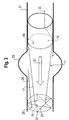
- the vascular graft shown comprises an elongated tubular body 11 which is divided into a portion 11-1 and a portion 11-2.
- the portion 11-1 of the body 11 is conical and has a blood-impermeable wall 17.
- In the longitudinal direction of the section 11-1 is limited by an inlet opening 13 and an outlet opening 15, which are interconnected by a conical passage 19, which is bounded in the radial direction by the wall 17.
- the second section 11-2 has a cylindrical shape and, at the entrance opening side, directly adjoins the first section 11-1 of the body 11.
- the second section 11-2 is optional and may be omitted.
- the inlet opening 13 has a larger cross-sectional area than the outlet opening 15, i. the inner diameter or the lumen of the inlet opening 13 is greater than the inner diameter or the lumen of the outlet opening 15th
- the vascular implant with the body 11 is inserted into a blood vessel 27 which locally has a cross-sectional area expansion 29, ie, an aneurysm.
- the body 11 abuts with its cylindrical portion 11-2 and in the region of the inlet opening 13 in an unexpanded region of the blood vessel 27 on the vessel wall, wherein the outer diameter of the cylindrical portion 11-2 and the outer diameter are selected to be slightly larger than the inner diameter of the blood vessel 27 in the region of the inlet opening 13, so that the cylindrical portion 11-2 of the body 11 bears against the vessel wall under tension, whereby a firm support of the vascular implant is achieved.
- the section 11-2 is designed as a mesh to promote ingrowth of the cells of the vessel wall of the blood vessel 27.
- the body 11 of the vascular implant may be formed as a self-expanding stent consisting in particular of Nitinol, which is introduced into the blood vessel 27 in a compressed state by means of a catheter and automatically expands into a state of larger radius upon withdrawal due to the blood temperature, so that the cylindrical portion 11-2 abuts against the vessel wall.
- the body 11 of the vascular implant may consist, for example, of stainless steel or of spring steel and, in particular, to expand it via a balloon until the cylindrical section 11-2 comes into contact with the vessel wall.
- the body 11 opens freely in the blood vessel 27.
- the length of the body 11 is sufficient to completely span the aneurysm 29.
- the outlet opening 15 of the body 11 is located in the region of the aneurysm 29, as long as it is ensured that a negative pressure is generated within the aneurysm 29 due to the described water jet pumping effect.
- Blood flowing through the blood vessel 27 in the flow direction 31 enters and leaves via the cylindrical portion 11-2 and through the inlet 13 into the conical portion 11-1 of the body 11 through the outlet opening 15, wherein within the conical section 11-2, the flow rate increases steadily due to the continuously narrowing through-channel 19.
- Fig. 2 The vascular implant shown corresponds essentially to the one in Fig. 1 shown vascular implant.
- a conical stent 21 with blood-permeable wall which tapers in the same direction as the conical portion 11-1 of the body 11.
- the conical stent 21 having a larger opening angle than the conical body portion 11-1 is attached to the body 11 with its tapered end in the region of the outlet opening 15.
- the conical stent 21 is designed as a fixing means and is supported on the vessel wall of the blood vessel 27 with its end points 23 facing away from the body 11. As a result, the body 11 in the region of the outlet opening 15 of the vessel wall of the Blood vessel 27 spaced and centered within the blood vessel 27 held.
- fixing means 21 shown are merely exemplary in nature.
- any differently shaped blood-permeable fixing means can be provided which can keep the end of the body 11 having the outlet opening 15 away from the vessel wall of the blood vessel 27 and centered within the blood vessel 27.
- a plurality of radially outwardly projecting fixing elements 21 may be provided.
- the fixing elements 21 are designed in the form of a star whose end points 23 remote from the body 11 are arranged on an imaginary circular line 25, which is dimensioned such that the end points 23 rest against the vessel wall of the blood vessel 27.
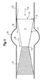
- the vascular implant shown fixing means are formed as a blood-permeable conical stent 21, which consists of a mesh, so that a total of a double frustoconical vascular graft is formed, which has a constriction in the center.
- the in the FIGS. 2 to 4 Fixing means 21 shown may each be integrally formed with the body 11 or connected in the region of the outlet opening 15 with the body 11.
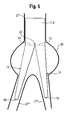
- Vascular implant shown is at least substantially Y-shaped and comprises two substantially as described above body 11, which are each formed conically.
- the two bodies 11 are connected to one another in the region of their inlet openings 13 at a branch 37 of the vascular implant, wherein a common cylindrical section 11-2 is provided for the two bodies 11.
- the vascular implant according to this embodiment is particularly suitable for use in an abdominal aortic aneurysm 27, wherein in the implanted state the cylindrical portion 11-2 upstream of the aneurysm 29 fixed in the abdominal aorta 27 'and is largely sealed against the vessel wall, at least in the transition region to the inlet openings 13 and the two bodies 11 with their outlet openings 15 each end in a leg artery 27 "fixed or unfixed.
Landscapes
- Health & Medical Sciences (AREA)
- Engineering & Computer Science (AREA)
- Biomedical Technology (AREA)
- Cardiology (AREA)
- Oral & Maxillofacial Surgery (AREA)
- Transplantation (AREA)
- Heart & Thoracic Surgery (AREA)
- Vascular Medicine (AREA)
- Life Sciences & Earth Sciences (AREA)
- Animal Behavior & Ethology (AREA)
- General Health & Medical Sciences (AREA)
- Public Health (AREA)
- Veterinary Medicine (AREA)
- Gastroenterology & Hepatology (AREA)
- Pulmonology (AREA)
- Prostheses (AREA)
Abstract
Description
- Die vorliegende Erfindung betrifft ein Gefäßimplantat zur Behandlung eines Aneurysmas, mit einem länglichen Körper, der eine Eintrittsöffnung, eine Austrittsöffnung sowie einen die Eintrittsöffnung mit der Austrittsöffnung verbindenden Durchgangskanal für durch das Blutgefäß strömendes Blut aufweist, wobei der Durchgangskanal in Umfangsrichtung durch eine blutundurchlässige Wand begrenzt ist.
- Bei einem Aneurysma handelt es sich um eine krankhafte, örtlich begrenzte Erweiterung, Ausbuchtung bzw. Aussackung eines Blutgefäßes, insbesondere einer Schlagader. Aneurysmata können an sämtlichen Abschnitten einer Schlagader auftreten. Besonders häufig sind Bauchaortenaneurysmata und Aneurysmata an Kniekehlenschlagadern vorzufinden. Aufgeweitete Blutgefäße unterliegen einer hohen Rupturgefahr, so dass das Risiko einer tödlichen Blutung besteht. Darüber hinaus neigen aufgeweitete Blutgefäße dazu, an Größe zuzunehmen. Die Rupturgefahr steigt mit zunehmendem Durchmesser des Aneurysmas, da der durch das durch das Blutgefäß strömende Blut auf die Gefäßwand des Blutgefäßes ausgeübte Druck mit zunehmender Gefäßweite zunimmt (Gesetz von Bernoulli).
- Es ist bekannt, derartig aufgeweitete Blutgefäße mit röhrenförmigen bzw. schlauchförmigen Implantaten, welche auch als Stents bezeichnet werden, zu versorgen. Hierbei wird ein Stent mit einer blutundurchlässigen Wand in das betroffene Blutgefäß derart eingesetzt, dass mittels des Stents das Aneurysma überbrückt werden kann. Dabei wird der Stent mit seinen beiden Enden an den an den aufgeweiteten Bereich beidseitig anschließenden, nicht aufgeweiteten Bereichen des Blutgefäßes möglichst formschlüssig fixiert, wodurch eine Abdichtung der Aufweitung erreicht werden soll, um zu verhindern, dass weiterhin Blut in die Aufweitung fließt. Der Durchmesser eines derartigen Stents entspricht in etwa dem normalen Durchmesser eines Gefäßes.
- Bei diesen Lösungen besteht jedoch das Problem, dass durch ungenügende Adaption an das natürliche Gefäß häufig kleine Undichtigkeiten zwischen dem Stent und demjenigen Bereich der Gefäßwand des Blutgefäßes, an welchem der Stent fixiert ist, entstehen können. Insbesondere durch eintrittsöffnungsseitig vorhandene Undichtigkeiten oder durch Kollateralgefäße kann weiterhin Blut in das Aneurysma strömen, so dass die Rupturgefahr der Gefäßwand im Bereich des Aneurysmas nicht beseitigt wird.
- Der Erfindung liegt daher die Aufgabe zugrunde, ein Gefäßimplantat der eingangs genannten Art anzugeben, welches die Gefahr einer Ruptur der Gefäßwand im Bereich eines Aneurysmas verringert.
- Diese Aufgabe wird durch ein Gefäßimplantat mit den Merkmalen des Anspruchs 1 gelöst und insbesondere dadurch, dass die Eintrittsöffnung eine größere Querschnittsfläche besitzt als die Austrittsöffnung.
- Bevorzugt wird das Gefäßimplantat mit dem die Eintrittsöffnung aufweisenden Ende und/oder einem an die Eintrittsöffnung unmittelbar anschließenden Abschnitt an dem stromaufwärts des Aneurysmas gelegenen, nicht aufgeweiteten Bereich des Blutgefäßes fixiert. Bevorzugt besitzt das Gefäßimplantat eine Länge, welche sich über die gesamte Länge des Aneurysmas hinweg erstrecken kann.
- Nach dem Kontinuitätsgesetz für inkompressible Fluide tritt aus der Austrittsöffnung des Körpers dasselbe Blutvolumen aus, das an der Eintrittsöffnung des Körpers in diesen eingeströmt ist, d.h. der Volumenstrom bzw. das Volumen, das sich innerhalb einer Zeiteinheit durch einen Querschnitt des Körpers bewegt, ist an der Eintrittsöffnung und an der Austrittsöffnung der- bzw. dasselbe. Hieraus ergibt sich, dass das durch das Blutgefäß und damit den Körper strömende Blut die Austrittsöffnung mit einer höheren Geschwindigkeit passiert als die Eintrittsöffnung. Durch die höhere Geschwindigkeit entsteht an dem die Austrittsöffnung aufweisenden Ende des Körpers - wie bei einer Wasserstrahlpumpe - ein Unterdruck, durch den das in einem Aneurysma befindliche Blut abgesaugt wird. Auf diese Weise entsteht auch innerhalb des Aneurysmas ein entsprechender Unterdruck, so dass die aufgeweitete Gefäßwand entlastet wird.
- Dieser Effekt tritt selbst dann auf, wenn das Gefäßimplantat eintrittsöff nungsseitig nicht vollständig abgedichtet ist. Somit kann mit dem erfindungsgemäß ausgebildeten Gefäßimplantats die Gefahr einer Ruptur der Gefäßwand des Aneurysmas wirksam verringert werden.
- Da eine stromabwärtsseitige Abdichtung des Aneurysmas durch das Gefäßimplantat nicht erforderlich ist und selbst stromaufwärts die Abdichtung nicht 100%ig sein muss, kann das Gefäßimplantat auch in solchen Fällen verwendet werden, bei denen eine abdichtende Fixierung an dem Blutgefäß stromaufwärts und/oder stromabwärts des Aneurysmas nicht möglich ist. Da stromabwärts des Aneurysmas eine Abdichtung nicht erforderlich ist, kann das erfindungsgemäße Gefäßimplantat auch bei einem Bauchaortenaneurysma eingesetzt werden, welches unmittelbar an der Abzweigung zu den beiden Beinschlagadern beginnt. Auf eine Fixierung stromabwärts des Aneurysmas kann entweder verzichtet werden oder es kann eine blutdurchlässige Fixierung verwendet werden. Für ein Bauchaortenaneurysma, welches unmittelbar an den Abzweigungen zu den beiden Nierenschlagadern beginnt, kann das Gefäßimplantat mit einem an die Eintrittsöffnung des Körpers insbesondere unmittelbar anschließenden Fixierabschnitt versehen sein, welcher blutdurchlässig ausgebildet ist, um die Abzweigungen zu den Nierenschlagadern nicht zu verschließen.
- Nach einer Ausbildung der Erfindung verjüngt sich der Körper, ein zwischen der Eintrittsöffnung und der Austrittsöffnung befindlicher Abschnitt des Körpers und/oder der Durchgangskanal von der Eintrittsöffnung zur Austrittsöffnung hin. Hierdurch kann über die gesamte Länge des Körpers eine allmähliche Querschnittsflächenreduzierung von der Eintrittsöffnung zur Austrittsöffnung erreicht werden, um beispielsweise Verwirbelungen im Blutstrom zu vermeiden. Die Verjüngung ist bevorzugt gleichmäßig, kontinuierlich und/oder konisch ausgebildet.
- Bevorzugt ist der Körper im Bereich der Eintrittsöffnung und/oder an einem an die Eintrittsöffnung anschließenden Abschnitt des Körpers zur Anlage an der Gefäßwand des Blutgefäßes ausgebildet. Die Außenquerschnittsfläche des Körpers im Bereich der Eintrittsöffnung und/ oder des an die Eintrittsöffnung anschließenden Abschnitts ist insbesondere derart dimensioniert, dass im implantierten Zustand der Körper im Bereich der Eintrittsöffnung und/oder mit dem an die Eintrittsöffnung anschließenden Abschnitt an der Gefäßwand des Blutgefäßes anliegt. Hierdurch kann eine Fixierung des Körpers im Blutgefäß erreicht werden.
- Um eine besonders gute Fixierung des Gefäßimplantats im Blutgefäß zu erreichen, kann es vorteilhaft sein, wenn der an die Eintrittsöffnung anschließende Abschnitt des Körpers zylinderförmig ausgebildet ist. Der Körper kann somit über einen größeren Bereich hinweg an den Innendurchmesser des Blutgefäßes adaptiert werden.
- Besonders bevorzugt ist es, wenn der an die Eintrittsöffnung anschließende Abschnitt des Körpers eine blutdurchlässig ausgebildete Wand besitzt. Der an die Eintrittsöffnung anschließende Abschnitt kann beispielsweise als Gittergeflecht ausgebildet sein. Hierdurch wird ein Einwachsen der Zellen der Gefäßwand des Blutgefäßes in den Körper des Implantats gefördert und damit eine besonders feste Fixierung geschaffen.
- Nach einer weiteren Ausbildung der Erfindung ist die äußere Abmessung des Körpers im Bereich der Austrittsöffnung derart dimensioniert ist, dass der Körper im Bereich der Austrittsöffnung von der Gefäßwand des Blutgefäßes beabstandet ist. Dies kann insbesondere dann der Fall sein, wenn sich neben der Querschnittsfläche des Durchgangskanals auch die äußere Abmessung des Körpers zu der die Austrittsöffnung aufweisenden Seite hin verjüngt.
- Bevorzugt ist der Körper mit blutdurchlässigen Fixiermitteln für das austrittsöffnungsseitige Ende des Körpers versehen ist, welche zur Anlage an der Gefäßwand des Blutgefäßes ausgebildet sind. Hierdurch kann ein seitliches Hin- und Herwandern des die Austrittsöffnung aufweisenden Endes des Körpers in der Blutströmung verhindert werden, so dass eine radiale Fixierung innerhalb des Blutgefäßes erreicht wird. Die Fixiermittel sind blutdurchlässig ausgebildet, um ein durch den erzeugten Unterdruck bewirktes Absaugen des Bluts aus dem Aneurysma möglichst wenig zu behindern.
- Die Fixiermittel können dazu ausgebildet sein, den Körper im Bereich der Austrittsöffnung von der Gefäßwand des Blutgefäßes beabstandet zu halten. Hierdurch wird gewährleistet, dass das die Austrittsöffnung aufweisende Ende des Körpers nicht an der Gefäßwand des Blutgefäßes anliegt, so dass der vorstehend erläuterte Wasserstrahlpumpeneffekt vollumfänglich um die Austrittsöffnung herum auftreten kann. Insbesondere können die Fixiermittel derart ausgebildet sein, dass die Austrittsöffnung oder das die Austrittsöffnung aufweisende Ende des Körpers zentriert innerhalb des Blutgefäßes gehalten wird.
- Nach einer weiteren Ausbildung der Erfindung sind die Fixiermittel im Bereich der Austrittsöffnung an dem Körper vorgesehen.
- Die Fixiermittel können als ein Gittergeflecht, mehrere jeweils mit einer radialen Komponente von dem Körper abstehende Fixierelemente und/oder ein konischer Stent ausgebildet sein.
- Der Körper oder ein Teil hiervon kann mit den Fixiermitteln einteilig ausgebildet sein. Die Fixiermittel können jedoch auch als separates Teil oder als separate Teile ausgebildet sein, das/die mit dem Körper oder einem Teil hiervon verbunden ist/ sind.
- Die Wand des Körpers kann starr, flexibel oder teils starr und flexibel ausgebildet sein. Bei der Wand kann es sich beispielsweise um ein Gittergeflecht in Form eines Stents handeln, welches mit einer Beschichtung versehen ist. Die Beschichtung kann dabei an der Außenseite, an der Innenseite oder sowohl an der Außenseite wie auch an der Innenseite des Gittergeflechts vorgesehen sein. Bevorzugt ist die Wand aus biokompatiblem Material hergestellt. Beispielsweise kann das Gittergeflecht als selbstexpandierender oder als ballonexpandierender Stent ausgebildet sein. Während bei einer starren Ausbildung das Gefäßimplantat beispielsweise operativ in das Blutgefäß eingesetzt wird, ist bei einer zumindest teilflexiblen Ausbildung eine transluminale Implantation möglich.
- Das Gefäßimplantat, insbesondere der Körper oder die Wand des Körpers, kann mehrteilig aufgebaut sein. In diesem Fall können die einzelnen Teile getrennt voneinander in das Blutgefäß eingebracht und/oder innerhalb des Blutgefäßes abgesetzt werden. Beispielsweise kann bei einer mehrteilig ausgebildeten Wand, welche eine blutundurchlässige Hülle und eine Stützstruktur für die Hülle, beispielsweise ein Gittergeflecht, umfasst, die Hülle getrennt von der Stützstruktur und/oder getrennt von Fixiermitteln für den Körper in das Blutgefäß eingebracht und/oder innerhalb des Blutgefäßes abgesetzt werden. Bei einer getrennten Einbringung, beispielsweise hintereinander liegend auf einem Katheter oder aufeinanderfolgend jeweils mit unterschiedlichen Kathetern, kann der Zugang für den Katheter kleiner gewählt werden, so dass die Wundheilung verbessert wird.
- Es ist beispielsweise möglich, dass zunächst lediglich die Hülle eingebracht und abgesetzt wird, wobei diese bevorzugt nach dem Absetzen an einem Ende durch das Einführinstrument gehalten wird. Anschließend kann die Stützstruktur in die Hülle eingesetzt werden, so dass beim Aufweiten der Stützstruktur gleichzeitig die Hülle mit aufgeweitet wird und diese durch die Stützstruktur gegen die Gefäßwand gedrückt und durch gehalten wird. Falls gewünscht, können in einem nächsten Schritt die Fixiermittel eingebracht und mit dem aus Stützstruktur und Hülle gebildeten Körper verbunden werden.
- Die Wand kann auch lediglich eine blutundurchlässige Hülle, insbesondere ohne eine Stützstruktur, umfassen. Die Hülle kann dann beispielsweise an einem an die Eintrittsöffnung stromaufwärts anschließenden, insbesondere von der Hülle getrennt ausgebildeten Abschnitt des Körpers befestigt sein oder von diesem zur Befestigung gegen die Gefäßwand gedrückt werden. In diesem Fall besitzt die Stützstruktur bevorzugt eine kurze Länge, so dass sie nur stromaufwärts des Aneurysmas zu liegen kommt oder nur über einen insbesondere relative kurzen Teilbereich in das Aneurysma hineinragt.
- Die vorliegende Erfindung betrifft weiterhin ein Gefäßimplantat, mit zwei Körpern, welche jeweils wie vorstehend erläutert ausgebildet sind, wobei die Körper an einer Abzweigung des Gefäßimplantats im Bereich ihrer Eingangsöffnungen miteinander verbunden sind. Ein derartiges Gefäßimplantat kann beispielsweise bei einem Bauchaortenaneurysma im Bereich der Abzweigung zu den beiden Beinschlagadern verwendet werden.
- Insbesondere können die beiden Körper einen an die Abzweigung anschließenden gemeinsamen Abschnitt zur Anlage an der Gefäßwand des Blutgefäßes aufweisen.
- Nicht beschränkende Ausführungsbeispiele der Erfindung sind in der Zeichnung dargestellt und werden nachfolgend beschrieben.
- Es zeigen, jeweils in schematischer Darstellung,
- Fig.1
- ein erste Ausführungsform eines erfindungsgemäßen Gefäßimplantats,
- Fig. 2
- das Gefäßimplantat aus
Fig. 1 mit Fixierelementen, - Fig. 3
- das Gefäßimplantat aus
Fig. 1 mit sternförmigen Fixiermitteln, - Fig. 4
- das Gefäßimplantat aus
Fig. 1 mit als konischen Stent ausgebildeten Fixiermitteln, und - Fig. 5
- ein weitere Ausführungsform eines erfindungsgemäßen Gefäßimplantats.
- Das in
Fig. 1 gezeigte Gefäßimplantat umfasst einen länglichen, röhrenförmigen Körper 11, welcher in einen Abschnitt 11-1 und einen Abschnitt 11-2 aufgeteilt ist. Der Abschnitt 11-1 des Körpers 11 ist konisch ausgebildet und weist eine blutundurchlässige Wand 17 auf. In Längsrichtung ist der Abschnitt 11-1 durch eine Eintrittsöffnung 13 und eine Austrittsöffnung 15 begrenzt, welche durch einen konischen Durchgangskanal 19 miteinander verbunden sind, der in radialer Richtung durch die Wand 17 begrenzt ist. Der zweite Abschnitt 11-2 ist zylinderförmig ausgebildet und schließt eintrittsöffnungsseitig unmittelbar an den ersten Abschnitt 11-1 des Körpers 11 an. Der zweite Abschnitt 11-2 ist jedoch optional und kann auch weggelassen werden. - Die Eintrittsöffnung 13 besitzt eine größere Querschnittsfläche als die Austrittsöffnung 15, d.h. der innere Durchmesser bzw. das Lumen der Eintrittsöffnung 13 ist größer als der innere Durchmesser bzw. das Lumen der Austrittsöffnung 15.
- Das Gefäßimplantat mit dem Körper 11 ist in ein Blutgefäß 27 eingesetzt, welches lokal eine Querschnittsflächenaufweitung 29, d.h. ein Aneurysma, aufweist. Der Körper 11 liegt mit seinem zylinderförmigen Abschnitt 11-2 und im Bereich der Eintrittsöffnung 13 in einem nicht aufgeweiteten Bereich des Blutgefäßes 27 an dessen Gefäßwand an, wobei der Außendurchmesser des zylinderförmigen Abschnitts 11-2 und der Außendurchmesser im Bereich der Eintrittsöffnung 13 geringfügig größer gewählt sind als der Innendurchmesser des Blutgefäßes 27, so dass der zylinderförmige Abschnitt 11-2 des Körpers 11 unter Spannung an der Gefäßwand anliegt, wodurch eine feste Halterung des Gefäßimplantats erreicht wird. Der Abschnitt 11-2 ist als Gittergeflecht ausgebildet sein, um ein Einwachsen der Zellen der Gefäßwand des Blutgefäßes 27 zu fördern.
- Die Festlegung des zylinderförmigen Abschnitts 11-2 kann in an sich bekannter Weise erfolgen. Beispielsweise kann der Körper 11 des Gefäßimplantats als insbesondere aus Nitinol bestehender, selbstexpandierender Stent ausgebildet sein, der in einem komprimierten Zustand mittels eines Katheters in das Blutgefäß 27 eingebracht wird und nach Absetzen aufgrund der Bluttemperatur automatisch in einen Zustand mit größerem Radius expandiert, so dass sich der zylinderförmige Abschnitt 11-2 an die Gefäßwand anlegt. Es ist auch möglich, dass der Körper 11 des Gefäßimplantats beispielsweise aus Edelstahl oder aus Federstahl besteht und insbesondere über einen Ballon aufgeweitet wird, bis der zylindrische Abschnitt 11-2 an der Gefäßwand zur Anlage kommt.
- Austrittsöffnungsseitig mündet der Körper 11 frei im Blutgefäß 27. Die Länge des Körpers 11 reicht aus, um das Aneurysma 29 vollständig zu überspannen. Es ist grundsätzlich jedoch auch denkbar, dass sich die Austrittsöffnung 15 des Körpers 11 im Bereich des Aneurysmas 29 befindet, solange gewährleistet ist, dass aufgrund des beschriebenen Wasserstrahlpumpeneffekts innerhalb des Aneurysmas 29 ein Unterdruck erzeugt wird.
- Durch das Blutgefäß 27 in Flussrichtung 31 strömendes Blut tritt über den zylindrischen Abschnitt 11-2 und durch die Eintrittsöffnung 13 in den konischen Abschnitt 11-1 des Körper 11 ein und verlässt diesen durch die Austrittsöffnung 15, wobei innerhalb des konischen Abschnitts 11-2 die Fließgeschwindigkeit aufgrund des sich kontinuierlich verengenden Durchgangskanals 19 stetig zunimmt.
- Zwischen der Gefäßwand des Blutgefäßes 27 und dem die blutundurchlässige Wand 17 aufweisenden konischen Abschnitt 11-1 des Körpers 11 im Bereich der Eintrittsöffnung 13 durch eine Undichtigkeit gemäß einem Pfeil 33 hindurch tretendes Blut, welches sich in dem Aneurysma 29 sammelt, wird durch das mit erhöhter Geschwindigkeit aus der Austrittsöffnung 15 strömende Blut aufgrund des vorstehend erläuterten Wasserstrahlpumpeneffekts in Flussrichtung 31 gefördert, so dass innerhalb des Aneurysmas 29 ein Unterdruck entsteht und der Aufbau eines zu hohen Drucks auf die Gefäßwand des Blutgefäßes 27 im Bereich des Aneurysmas 29 verhindert werden kann. Die durch den Unterdruck zwischen dem Aneurysma 29 und dem die Austrittsöffnung 15 des Körpers 11 umgebenden Bereich des Blutgefäßes 27 auftretende Druckdifferenz ist durch einen Pfeil 35 veranschaulicht.
- Das in
Fig. 2 gezeigte Gefäßimplantat entspricht im Wesentlichen dem inFig. 1 gezeigten Gefäßimplantat. Im Unterschied zuFig. 1 weist das Gefäßimplantat gemäßFig. 2 jedoch einen konischen Stent 21 mit blutdurchlässiger Wand auf, welcher sich in dieselbe Richtung wie der konische Abschnitt 11-1 des Körpers 11 verjüngt. Der einen größeren Öffnungswinkel als der konische Körperabschnitt 11-1 aufweisende konische Stent 21 ist mit seinem verjüngten Ende im Bereich der Austrittsöffnung 15 an dem Körper 11 angebracht. Der konische Stent 21 ist als Fixiermittel ausgebildet und stützt sich mit seinen dem Körper 11 abgewandten Endpunkten 23 an der Gefäßwand des Blutgefäßes 27 ab. Hierdurch wird der Körper 11 im Bereich der Austrittsöffnung 15 von der Gefäßwand des Blutgefäßes 27 beabstandet und zentriert innerhalb des Blutgefäßes 27 gehalten. - Die in
Fig. 2 gezeigten Fixiermittel 21 sind jedoch lediglich beispielhafter Natur. Grundsätzlich können beliebig anders geformte blutdurchlässige Fixiermittel vorgesehen sein, welche das die Austrittsöffnung 15 aufweisende Ende des Körpers 11 von der Gefäßwand des Blutgefäßes 27 beabstandet und zentriert innerhalb des Blutgefäßes 27 halten können. Insbesondere können mehrere, radial nach außen abstehende Fixierelemente 21 vorgesehen sein. InFig. 3 sind die Fixierelemente 21 beispielsweise in Form eines Sternes ausgebildet, dessen von dem Körper 11 abgewandte Endpunkte 23 auf einer gedachten Kreislinie 25 angeordnet sind, welche derart dimensioniert ist, dass die Endpunkte 23 an der Gefäßwand des Blutgefäßes 27 anliegen. Bei dem inFig. 4 gezeigten Gefäßimplantat sind die Fixiermittel als blutdurchlässiger konischer Stent 21 ausgebildet, welcher aus einem Gittergeflecht besteht, so dass insgesamt ein doppelkegelstumpfförmiges Gefäßimplantat gebildet ist, welches mittig eine Einschnürung aufweist. Die in denFiguren 2 bis 4 gezeigten Fixiermittel 21 können mit dem Körper 11 jeweils einteilig ausgebildet oder im Bereich der Austrittsöffnung 15 mit dem Körper 11 verbunden sein. - Das in
Fig. 5 dargestellte Gefäßimplantat ist zumindest im Wesentlichen Y-förmig ausgebildet und umfasst zwei im Wesentlichen wie vorstehend beschriebene Körper 11, welche jeweils konisch ausgebildet sind. Die beiden Körper 11 sind im Bereich ihrer Eingangsöffnungen 13 an einer Abzweigung 37 des Gefäßimplantats miteinander verbunden, wobei für die beiden Körper 11 ein gemeinsamer zylindrischer Abschnitt 11-2 vorgesehen ist. Das Gefäßimplantat gemäß dieser Ausführungsform ist insbesondere dazu geeignet, bei einem Bauchaortenaneurysma 27 eingesetzt zu werden, wobei im implantierten Zustand der zylindrische Abschnitt 11-2 stromaufwärts des Aneurysmas 29 in der Bauchschlagader 27' fixiert sowie gegenüber der Gefäßwand zumindest im Übergangsbereich zu den Eintrittsöffnungen 13 weitgehend abgedichtet ist und die beiden Körper 11 mit ihren Austrittsöffnungen 15 jeweils in einer Beinschlagader 27" fixiert oder unfixiert enden. -
- 11
- Körper
- 13
- Eintrittsöffnung
- 15
- Austrittsöffnung
- 17
- Wand
- 19
- Durchgangskanal
- 21
- Fixiermittel
- 23
- Endpunkt
- 25
- Kreislinie
- 27
- Blutgefäß
- 29
- Aneurysma
- 31
- Flussrichtung
- 33
- Pfeil
- 35
- Pfeil
- 37
- Abzweigung
Claims (15)
- Gefäßimplantat zur Behandlung eines Aneurysmas, d.h. einer Aufweitung (29) der Querschnittsfläche eines Blutgefäßes (27), mit einem länglichen Körper (11), der eine Eintrittsöffnung (13), eine Austrittsöffnung (15) sowie einen die Eintrittsöffnung (13) mit der Austrittsöffnung (15) verbindenden Durchgangskanal (19) für durch das Blutgefäß (27) strömendes Blut aufweist, wobei der Durchgangskanal (19) in Umfangsrichtung durch eine blutundurchlässige Wand (17) begrenzt ist,
dadurch gekennzeichnet,
dass die Eintrittsöffnung (13) eine größere Querschnittsfläche besitzt als die Austrittsöffnung (15). - Gefäßimplantat nach Anspruch 1,
dadurch gekennzeichnet,
dass sich der Körper (11), ein zwischen der Eintrittsöffnung (13) und der Austrittsöffnung (15) befindlicher Abschnitt (11-1) des Körpers (11) und / oder der Durchgangskanal (19) von der Eintrittsöffnung (13) zur Austrittsöffnung (15) hin verjüngt. - Gefäßimplantat nach Anspruch 2,
dadurch gekennzeichnet,
dass die Verjüngung gleichmäßig, kontinuierlich und/oder konisch ausgebildet ist. - Gefäßimplantat nach einem der vorstehenden Ansprüche,
dadurch gekennzeichnet,
dass der Körper (11) im Bereich der Eintrittsöffnung (13) und/ oder an einem an die Eintrittsöffnung (13) anschließenden Abschnitt (11-2) des Körpers (11) zur Anlage an der Gefäßwand des Blutgefäßes (27) ausgebildet ist. - Gefäßimplantat nach nach Anspruch 4,
dadurch gekennzeichnet,
dass der an die Eintrittsöffnung (13) anschließende Abschnitt (11-2) des Körpers (11) zylinderförmig ausgebildet ist. - Gefäßimplantat nach Anspruch 4 oder 5,
dadurch gekennzeichnet,
dass der an die Eintrittsöffnung (13) anschließende Abschnitt (11-2) des Körpers (11) eine blutdurchlässig ausgebildete Wand besitzt. - Gefäßimplantat nach einem der vorstehenden Ansprüche,
dadurch gekennzeichnet,
dass die äußere Abmessung des Körpers (11) im Bereich der Austrittsöffnung (15) derart dimensioniert ist, dass der Körper (11) im Bereich der Austrittsöffnung (15) von der Gefäßwand des Blutgefäßes (27) beabstandet ist. - Gefäßimplantat nach einem der vorstehenden Ansprüche,
dadurch gekennzeichnet,
dass der Körper (11) mit blutdurchlässigen Fixiermitteln (21) für das austrittsöffnungsseitige Ende des Körpers (11) versehen ist, welche zur Anlage an der Gefäßwand des Blutgefäßes (27) ausgebildet sind. - Gefäßimplantat einem der Ansprüche 8,
dadurch gekennzeichnet,
dass die Fixiermittel (21) dazu ausgebildet sind, den Körper (11) im Bereich der Austrittsöffnung (15) von der Gefäßwand des Blutgefäßes (27) beabstandet zu halten. - Gefäßimplantat nach Anspruch 8 oder 9,
dadurch gekennzeichnet,
dass die Fixiermittel (21) im Bereich der Austrittsöffnung (15) an dem Körper (11) vorgesehen sind. - Gefäßimplantat nach einem der Ansprüche 8 bis 10,
dadurch gekennzeichnet,
dass die Fixiermittel (21) als ein Gittergeflecht, mehrere jeweils mit einer radialen Komponente von dem Körper (11) abstehende Fixierelemente und/oder ein konischer Stent ausgebildet sind. - Gefäßimplantat nach einem der Ansprüche 8 bis 11,
dadurch gekennzeichnet,
dass der Körper (11) oder ein Teil hiervon mit den Fixiermitteln (21) einteilig ausgebildet ist. - Gefäßimplantat nach einem der vorstehenden Ansprüche,
dadurch gekennzeichnet,
dass die Wand (17) des Körpers (11) starr, flexibel oder teils starr und teils flexibel ist und/oder dass das Gefäßimplantat, insbesondere der Körper (11) oder die Wand (17) des Körpers (11), mehrteilig aufgebaut ist. - Gefäßimplantat, mit zwei Körpern (11) jeweils gemäß einem der vorstehenden Ansprüche, wobei die Körper (11) an einer Abzweigung (37) des Gefäßimplantats im Bereich ihrer Eingangsöffnungen (13) miteinander verbunden sind.
- Gefäßimplantat nach Anspruch 14,
dadurch gekennzeichnet,
dass die beiden Körper (11) einen an die Abzweigung (37) anschließenden gemeinsamen Abschnitt (11-2) zur Anlage an der Gefäßwand des Blutgefäßes (27) aufweisen.
Applications Claiming Priority (1)
| Application Number | Priority Date | Filing Date | Title |
|---|---|---|---|
| DE102007019058A DE102007019058A1 (de) | 2007-04-23 | 2007-04-23 | Gefäßimplantat zur Behandlung eines Aneurysmas |
Publications (3)
| Publication Number | Publication Date |
|---|---|
| EP1985258A2 true EP1985258A2 (de) | 2008-10-29 |
| EP1985258A3 EP1985258A3 (de) | 2009-11-18 |
| EP1985258B1 EP1985258B1 (de) | 2013-11-27 |
Family
ID=39627406
Family Applications (1)
| Application Number | Title | Priority Date | Filing Date |
|---|---|---|---|
| EP08007336.4A Not-in-force EP1985258B1 (de) | 2007-04-23 | 2008-04-14 | Gefäßimplantat zur Behandlung eines Aneurysmas |
Country Status (3)
| Country | Link |
|---|---|
| US (2) | US20080262604A1 (de) |
| EP (1) | EP1985258B1 (de) |
| DE (1) | DE102007019058A1 (de) |
Cited By (1)
| Publication number | Priority date | Publication date | Assignee | Title |
|---|---|---|---|---|
| US10646360B2 (en) | 2007-04-23 | 2020-05-12 | Max Stengel | Vessel implant for the treatment of an aneurysm |
Families Citing this family (14)
| Publication number | Priority date | Publication date | Assignee | Title |
|---|---|---|---|---|
| US9282967B2 (en) | 2007-08-02 | 2016-03-15 | Bioconnect Systems, Inc. | Implantable flow connector |
| JP2010535072A (ja) | 2007-08-02 | 2010-11-18 | バイオコネクト システムズ | 埋め込み型フローコネクタ |
| US9211202B2 (en) * | 2008-10-24 | 2015-12-15 | Wisconsin Alumni Research Foundation | Apparatus and method for treating an aneurysm |
| US20120071965A1 (en) * | 2010-09-17 | 2012-03-22 | Longo Michael A | Implantable graft connector |
| EP3275402B1 (de) * | 2011-03-17 | 2021-08-25 | PQ Bypass, Inc. | Stent für differentielle dilatation |
| US10434293B2 (en) | 2012-04-15 | 2019-10-08 | Tva Medical, Inc. | Implantable flow connector |
| US9314600B2 (en) | 2012-04-15 | 2016-04-19 | Bioconnect Systems, Inc. | Delivery system for implantable flow connector |
| US9849006B2 (en) | 2013-03-15 | 2017-12-26 | Children's Medical Center Corporation | Methods and apparatuses for treating vessels |
| ES2875921T3 (es) * | 2015-12-22 | 2021-11-11 | Medira Ag | Dispositivo protésico de mejora de coaptación de válvula mitral |
| CN108210134B (zh) * | 2018-02-27 | 2024-05-10 | 北京航空航天大学 | 一种血管支架 |
| AT521414B1 (de) * | 2018-06-18 | 2021-01-15 | Mohl Werner | Stent-Pumpe |
| CN109350316B (zh) * | 2018-11-06 | 2024-03-12 | 广东工业大学 | 一种血管支架单体及血管支架 |
| PL3941392T3 (pl) | 2019-03-20 | 2025-08-25 | inQB8 Medical Technologies, LLC | Implant do leczenia rozwarstwienia aorty |
| TR2022020723A1 (tr) * | 2022-12-27 | 2024-07-22 | Bahcesehir Ueniversitesi | Beyin kanaması sonrası oluşan hasarı azaltan bir stent. |
Family Cites Families (54)
| Publication number | Priority date | Publication date | Assignee | Title |
|---|---|---|---|---|
| US5876445A (en) * | 1991-10-09 | 1999-03-02 | Boston Scientific Corporation | Medical stents for body lumens exhibiting peristaltic motion |
| US5609627A (en) * | 1994-02-09 | 1997-03-11 | Boston Scientific Technology, Inc. | Method for delivering a bifurcated endoluminal prosthesis |
| US6165213A (en) * | 1994-02-09 | 2000-12-26 | Boston Scientific Technology, Inc. | System and method for assembling an endoluminal prosthesis |
| US5653743A (en) * | 1994-09-09 | 1997-08-05 | Martin; Eric C. | Hypogastric artery bifurcation graft and method of implantation |
| US5709704A (en) * | 1994-11-30 | 1998-01-20 | Boston Scientific Corporation | Blood clot filtering |
| US6348066B1 (en) * | 1995-11-07 | 2002-02-19 | Corvita Corporation | Modular endoluminal stent-grafts and methods for their use |
| US6929659B2 (en) * | 1995-11-07 | 2005-08-16 | Scimed Life Systems, Inc. | Method of preventing the dislodgment of a stent-graft |
| DE69526857T2 (de) * | 1995-11-27 | 2003-01-02 | Schneider (Europe) Gmbh, Buelach | Stent zur Anwendung in einem körperlichen Durchgang |
| US6015431A (en) * | 1996-12-23 | 2000-01-18 | Prograft Medical, Inc. | Endolumenal stent-graft with leak-resistant seal |
| US5827321A (en) * | 1997-02-07 | 1998-10-27 | Cornerstone Devices, Inc. | Non-Foreshortening intraluminal prosthesis |
| US5855597A (en) * | 1997-05-07 | 1999-01-05 | Iowa-India Investments Co. Limited | Stent valve and stent graft for percutaneous surgery |
| US6102938A (en) * | 1997-06-17 | 2000-08-15 | Medtronic Inc. | Endoluminal prosthetic bifurcation shunt |
| US6120534A (en) * | 1997-10-29 | 2000-09-19 | Ruiz; Carlos E. | Endoluminal prosthesis having adjustable constriction |
| US6325820B1 (en) * | 1998-11-16 | 2001-12-04 | Endotex Interventional Systems, Inc. | Coiled-sheet stent-graft with exo-skeleton |
| US6458153B1 (en) * | 1999-12-31 | 2002-10-01 | Abps Venture One, Ltd. | Endoluminal cardiac and venous valve prostheses and methods of manufacture and delivery thereof |
| AU2002252307B2 (en) * | 2001-03-13 | 2007-07-05 | Medinol, Ltd. | Method and apparatus for stenting |
| AU2002248765B2 (en) * | 2001-03-28 | 2006-11-30 | Cook Medical Technologies Llc | Modular stent graft assembly and use thereof |
| US7377938B2 (en) * | 2001-07-19 | 2008-05-27 | The Cleveland Clinic Foundation | Prosthetic cardiac value and method for making same |
| US20050070992A1 (en) * | 2001-11-28 | 2005-03-31 | Aptus Endosystems, Inc. | Prosthesis systems and methods sized and configured for the receipt and retention of fasteners |
| US6893413B2 (en) * | 2002-01-07 | 2005-05-17 | Eric C. Martin | Two-piece stent combination for percutaneous arterialization of the coronary sinus and retrograde perfusion of the myocardium |
| US7044962B2 (en) * | 2002-06-25 | 2006-05-16 | Scimed Life Systems, Inc. | Implantable prosthesis with displaceable skirt |
| US7001425B2 (en) * | 2002-11-15 | 2006-02-21 | Scimed Life Systems, Inc. | Braided stent method for its manufacture |
| US7604660B2 (en) * | 2003-05-01 | 2009-10-20 | Merit Medical Systems, Inc. | Bifurcated medical appliance delivery apparatus and method |
| US7201772B2 (en) * | 2003-07-08 | 2007-04-10 | Ventor Technologies, Ltd. | Fluid flow prosthetic device |
| DE10335649A1 (de) * | 2003-07-30 | 2005-02-24 | Jotec Gmbh | Flechtstent zur Implantation in ein Blutgefäß |
| US20050085894A1 (en) * | 2003-10-16 | 2005-04-21 | Kershner James R. | High strength and lubricious materials for vascular grafts |
| US7144421B2 (en) * | 2003-11-06 | 2006-12-05 | Carpenter Judith T | Endovascular prosthesis, system and method |
| US8048140B2 (en) * | 2004-03-31 | 2011-11-01 | Cook Medical Technologies Llc | Fenestrated intraluminal stent system |
| US20070244520A1 (en) * | 2004-04-19 | 2007-10-18 | Searete Llc | Lumen-traveling biological interface device and method of use |
| CN100352406C (zh) * | 2004-08-17 | 2007-12-05 | 微创医疗器械(上海)有限公司 | 组合式可任意方向弯曲的覆膜支架 |
| US7695506B2 (en) * | 2004-09-21 | 2010-04-13 | Boston Scientific Scimed, Inc. | Atraumatic connections for multi-component stents |
| US8262720B2 (en) * | 2004-12-02 | 2012-09-11 | Nitinol Development Corporation | Prosthesis comprising dual tapered stent |
| WO2006127825A1 (en) * | 2005-05-23 | 2006-11-30 | Incept Llc | Apparatus and methods for locating an ostium of a vessel |
| EP1885289B1 (de) * | 2005-06-01 | 2013-01-09 | William A. Cook Australia Pty. Ltd. | Seitenzweig-stentprothese |
| US7670369B2 (en) * | 2005-10-13 | 2010-03-02 | Cook Incorporated | Endoluminal prosthesis |
| US20070213813A1 (en) * | 2005-12-22 | 2007-09-13 | Symetis Sa | Stent-valves for valve replacement and associated methods and systems for surgery |
| WO2007127362A2 (en) * | 2006-04-26 | 2007-11-08 | The Cleveland Clinic Foundation | Apparatus and method for treating cardiovascular diseases |
| US9408607B2 (en) * | 2009-07-02 | 2016-08-09 | Edwards Lifesciences Cardiaq Llc | Surgical implant devices and methods for their manufacture and use |
| US8747459B2 (en) * | 2006-12-06 | 2014-06-10 | Medtronic Corevalve Llc | System and method for transapical delivery of an annulus anchored self-expanding valve |
| US20080255678A1 (en) * | 2007-04-13 | 2008-10-16 | Cully Edward H | Medical apparatus and method of making the same |
| DE102007019058A1 (de) | 2007-04-23 | 2008-10-30 | Stengel, Max, Dr.Dr. | Gefäßimplantat zur Behandlung eines Aneurysmas |
| US8834551B2 (en) * | 2007-08-31 | 2014-09-16 | Rex Medical, L.P. | Vascular device with valve for approximating vessel wall |
| DE102007043830A1 (de) * | 2007-09-13 | 2009-04-02 | Lozonschi, Lucian, Madison | Herzklappenstent |
| US8715337B2 (en) * | 2007-11-09 | 2014-05-06 | Cook Medical Technologies Llc | Aortic valve stent graft |
| US9226813B2 (en) * | 2007-12-26 | 2016-01-05 | Cook Medical Technologies Llc | Low profile non-symmetrical stent |
| AU2009213159B2 (en) * | 2008-02-11 | 2013-02-21 | Cook Medical Technologies Llc | Prosthesis coupling device and method |
| US20090270971A1 (en) * | 2008-04-24 | 2009-10-29 | Medtronic Vascular, Inc. | Prosthesis Fixation Apparatus and Methods |
| US20090276040A1 (en) * | 2008-05-01 | 2009-11-05 | Edwards Lifesciences Corporation | Device and method for replacing mitral valve |
| EP2381889A1 (de) * | 2008-12-17 | 2011-11-02 | Abbott Laboratories Vascular Enterprises Limited | Körperlumenfilter mit ankern mit grosser oberfläche |
| US20100217382A1 (en) * | 2009-02-25 | 2010-08-26 | Edwards Lifesciences | Mitral valve replacement with atrial anchoring |
| CA2961767C (en) * | 2009-06-23 | 2018-08-14 | Endospan Ltd. | Vascular prostheses for treating aneurysms |
| US9132009B2 (en) * | 2010-07-21 | 2015-09-15 | Mitraltech Ltd. | Guide wires with commissural anchors to advance a prosthetic valve |
| US9381101B2 (en) * | 2012-04-23 | 2016-07-05 | The Charlotte-Mecklenburg Hospital Authority | Hybrid graft for therapy of aortic pathology and associated method |
| US20180021155A1 (en) * | 2016-07-21 | 2018-01-25 | Cook Medical Technologies Llc | Tapered body aaa graft |
-
2007
- 2007-04-23 DE DE102007019058A patent/DE102007019058A1/de not_active Withdrawn
-
2008
- 2008-04-14 EP EP08007336.4A patent/EP1985258B1/de not_active Not-in-force
- 2008-04-18 US US12/105,665 patent/US20080262604A1/en not_active Abandoned
-
2013
- 2013-07-29 US US13/953,094 patent/US10646360B2/en active Active
Non-Patent Citations (1)
| Title |
|---|
| None |
Cited By (1)
| Publication number | Priority date | Publication date | Assignee | Title |
|---|---|---|---|---|
| US10646360B2 (en) | 2007-04-23 | 2020-05-12 | Max Stengel | Vessel implant for the treatment of an aneurysm |
Also Published As
| Publication number | Publication date |
|---|---|
| US10646360B2 (en) | 2020-05-12 |
| EP1985258A3 (de) | 2009-11-18 |
| US20130310922A1 (en) | 2013-11-21 |
| EP1985258B1 (de) | 2013-11-27 |
| US20080262604A1 (en) | 2008-10-23 |
| DE102007019058A1 (de) | 2008-10-30 |
Similar Documents
| Publication | Publication Date | Title |
|---|---|---|
| EP1985258B1 (de) | Gefäßimplantat zur Behandlung eines Aneurysmas | |
| DE69735645T2 (de) | Endoluminales stent-gewebe mit leckbeständiger dichtung | |
| EP1653883B1 (de) | Stent zur implantation in ein blutgefäss, insbesondere im bereich des aortenbogens | |
| DE69734692T2 (de) | Vorrichtung zur Implantation einer Prothese in einem Körperkanal | |
| DE60030709T2 (de) | Aufblasbarer intraluminaler pfropfen | |
| DE69827192T2 (de) | Stent und Stent-Transplantat zur Behandlung von verzweigten Blutgefässen | |
| DE60019332T2 (de) | Balloneinbringungssystem und endovaskuläres implantat, leicht zum ausbringen | |
| DE60216426T2 (de) | Modulare stentendoprothese | |
| DE69434142T2 (de) | Aortenimplantat | |
| DE60319217T2 (de) | Stent mit segmentierter prothese | |
| DE10334868B4 (de) | Implantierbare Einrichtung als Organklappenersatz, dessen Herstellungsverfahren sowie Grundkörper und Membranelement dafür | |
| DE69835634T2 (de) | Intravaskulärer Stent und System zum Einführen (Obstruktion des Ostiums eines Gefässes) | |
| DE69624517T2 (de) | Expandierbarer stent mit herausragenden widerhaken | |
| DE69722940T2 (de) | Intravaskuläre prothese | |
| EP3397202B1 (de) | Selbstexpandierende gefässprothese | |
| EP3678589B1 (de) | Intraluminales gefässprothesensystem | |
| EP1891914A1 (de) | Katheter-Stent-Vorrichtung | |
| WO2007028452A1 (de) | Stentgraft-prothese | |
| WO2013113704A1 (de) | Modularer stentgraft | |
| WO2016071357A1 (de) | Modulares stentgraft-system | |
| DE69629698T2 (de) | Transplantat zum ausbessern eines aneurysmas | |
| WO2019012123A1 (de) | Intraluminale gefaessprothese | |
| EP3630009B1 (de) | Stentgraft mit taschen | |
| DE102005032308A1 (de) | Endovaskulares Implantat für den Verschluss eines Blutgefäßes | |
| WO2019072912A1 (de) | Expandierbares gefaessimplantat |
Legal Events
| Date | Code | Title | Description |
|---|---|---|---|
| PUAI | Public reference made under article 153(3) epc to a published international application that has entered the european phase |
Free format text: ORIGINAL CODE: 0009012 |
|
| AK | Designated contracting states |
Kind code of ref document: A2 Designated state(s): AT BE BG CH CY CZ DE DK EE ES FI FR GB GR HR HU IE IS IT LI LT LU LV MC MT NL NO PL PT RO SE SI SK TR |
|
| AX | Request for extension of the european patent |
Extension state: AL BA MK RS |
|
| PUAL | Search report despatched |
Free format text: ORIGINAL CODE: 0009013 |
|
| AK | Designated contracting states |
Kind code of ref document: A3 Designated state(s): AT BE BG CH CY CZ DE DK EE ES FI FR GB GR HR HU IE IS IT LI LT LU LV MC MT NL NO PL PT RO SE SI SK TR |
|
| AX | Request for extension of the european patent |
Extension state: AL BA MK RS |
|
| 17P | Request for examination filed |
Effective date: 20100512 |
|
| 17Q | First examination report despatched |
Effective date: 20100617 |
|
| AKX | Designation fees paid |
Designated state(s): AT BE BG CH CY CZ DE DK EE ES FI FR GB GR HR HU IE IS IT LI LT LU LV MC MT NL NO PL PT RO SE SI SK TR |
|
| REG | Reference to a national code |
Ref country code: DE Ref legal event code: R079 Ref document number: 502008010994 Country of ref document: DE Free format text: PREVIOUS MAIN CLASS: A61F0002060000 Ipc: A61F0002070000 |
|
| GRAP | Despatch of communication of intention to grant a patent |
Free format text: ORIGINAL CODE: EPIDOSNIGR1 |
|
| RIC1 | Information provided on ipc code assigned before grant |
Ipc: A61F 2/07 20130101AFI20130327BHEP |
|
| INTG | Intention to grant announced |
Effective date: 20130502 |
|
| GRAS | Grant fee paid |
Free format text: ORIGINAL CODE: EPIDOSNIGR3 |
|
| GRAP | Despatch of communication of intention to grant a patent |
Free format text: ORIGINAL CODE: EPIDOSNIGR1 |
|
| INTG | Intention to grant announced |
Effective date: 20130924 |
|
| GRAA | (expected) grant |
Free format text: ORIGINAL CODE: 0009210 |
|
| AK | Designated contracting states |
Kind code of ref document: B1 Designated state(s): AT BE BG CH CY CZ DE DK EE ES FI FR GB GR HR HU IE IS IT LI LT LU LV MC MT NL NO PL PT RO SE SI SK TR |
|
| REG | Reference to a national code |
Ref country code: GB Ref legal event code: FG4D Free format text: NOT ENGLISH |
|
| REG | Reference to a national code |
Ref country code: CH Ref legal event code: EP |
|
| REG | Reference to a national code |
Ref country code: AT Ref legal event code: REF Ref document number: 642367 Country of ref document: AT Kind code of ref document: T Effective date: 20131215 |
|
| REG | Reference to a national code |
Ref country code: IE Ref legal event code: FG4D Free format text: LANGUAGE OF EP DOCUMENT: GERMAN |
|
| REG | Reference to a national code |
Ref country code: DE Ref legal event code: R096 Ref document number: 502008010994 Country of ref document: DE Effective date: 20140123 |
|
| REG | Reference to a national code |
Ref country code: NL Ref legal event code: VDEP Effective date: 20131127 |
|
| REG | Reference to a national code |
Ref country code: LT Ref legal event code: MG4D |
|
| PG25 | Lapsed in a contracting state [announced via postgrant information from national office to epo] |
Ref country code: IS Free format text: LAPSE BECAUSE OF FAILURE TO SUBMIT A TRANSLATION OF THE DESCRIPTION OR TO PAY THE FEE WITHIN THE PRESCRIBED TIME-LIMIT Effective date: 20140327 Ref country code: LT Free format text: LAPSE BECAUSE OF FAILURE TO SUBMIT A TRANSLATION OF THE DESCRIPTION OR TO PAY THE FEE WITHIN THE PRESCRIBED TIME-LIMIT Effective date: 20131127 Ref country code: NL Free format text: LAPSE BECAUSE OF FAILURE TO SUBMIT A TRANSLATION OF THE DESCRIPTION OR TO PAY THE FEE WITHIN THE PRESCRIBED TIME-LIMIT Effective date: 20131127 Ref country code: FI Free format text: LAPSE BECAUSE OF FAILURE TO SUBMIT A TRANSLATION OF THE DESCRIPTION OR TO PAY THE FEE WITHIN THE PRESCRIBED TIME-LIMIT Effective date: 20131127 Ref country code: HR Free format text: LAPSE BECAUSE OF FAILURE TO SUBMIT A TRANSLATION OF THE DESCRIPTION OR TO PAY THE FEE WITHIN THE PRESCRIBED TIME-LIMIT Effective date: 20131127 Ref country code: NO Free format text: LAPSE BECAUSE OF FAILURE TO SUBMIT A TRANSLATION OF THE DESCRIPTION OR TO PAY THE FEE WITHIN THE PRESCRIBED TIME-LIMIT Effective date: 20140227 Ref country code: SE Free format text: LAPSE BECAUSE OF FAILURE TO SUBMIT A TRANSLATION OF THE DESCRIPTION OR TO PAY THE FEE WITHIN THE PRESCRIBED TIME-LIMIT Effective date: 20131127 |
|
| PG25 | Lapsed in a contracting state [announced via postgrant information from national office to epo] |
Ref country code: LV Free format text: LAPSE BECAUSE OF FAILURE TO SUBMIT A TRANSLATION OF THE DESCRIPTION OR TO PAY THE FEE WITHIN THE PRESCRIBED TIME-LIMIT Effective date: 20131127 Ref country code: CY Free format text: LAPSE BECAUSE OF FAILURE TO SUBMIT A TRANSLATION OF THE DESCRIPTION OR TO PAY THE FEE WITHIN THE PRESCRIBED TIME-LIMIT Effective date: 20131127 Ref country code: ES Free format text: LAPSE BECAUSE OF FAILURE TO SUBMIT A TRANSLATION OF THE DESCRIPTION OR TO PAY THE FEE WITHIN THE PRESCRIBED TIME-LIMIT Effective date: 20131127 |
|
| PG25 | Lapsed in a contracting state [announced via postgrant information from national office to epo] |
Ref country code: PT Free format text: LAPSE BECAUSE OF FAILURE TO SUBMIT A TRANSLATION OF THE DESCRIPTION OR TO PAY THE FEE WITHIN THE PRESCRIBED TIME-LIMIT Effective date: 20140327 |
|
| PG25 | Lapsed in a contracting state [announced via postgrant information from national office to epo] |
Ref country code: EE Free format text: LAPSE BECAUSE OF FAILURE TO SUBMIT A TRANSLATION OF THE DESCRIPTION OR TO PAY THE FEE WITHIN THE PRESCRIBED TIME-LIMIT Effective date: 20131127 |
|
| REG | Reference to a national code |
Ref country code: DE Ref legal event code: R097 Ref document number: 502008010994 Country of ref document: DE |
|
| PG25 | Lapsed in a contracting state [announced via postgrant information from national office to epo] |
Ref country code: CZ Free format text: LAPSE BECAUSE OF FAILURE TO SUBMIT A TRANSLATION OF THE DESCRIPTION OR TO PAY THE FEE WITHIN THE PRESCRIBED TIME-LIMIT Effective date: 20131127 Ref country code: SK Free format text: LAPSE BECAUSE OF FAILURE TO SUBMIT A TRANSLATION OF THE DESCRIPTION OR TO PAY THE FEE WITHIN THE PRESCRIBED TIME-LIMIT Effective date: 20131127 Ref country code: PL Free format text: LAPSE BECAUSE OF FAILURE TO SUBMIT A TRANSLATION OF THE DESCRIPTION OR TO PAY THE FEE WITHIN THE PRESCRIBED TIME-LIMIT Effective date: 20131127 Ref country code: RO Free format text: LAPSE BECAUSE OF FAILURE TO SUBMIT A TRANSLATION OF THE DESCRIPTION OR TO PAY THE FEE WITHIN THE PRESCRIBED TIME-LIMIT Effective date: 20131127 |
|
| PGFP | Annual fee paid to national office [announced via postgrant information from national office to epo] |
Ref country code: AT Payment date: 20140411 Year of fee payment: 7 |
|
| PG25 | Lapsed in a contracting state [announced via postgrant information from national office to epo] |
Ref country code: DK Free format text: LAPSE BECAUSE OF FAILURE TO SUBMIT A TRANSLATION OF THE DESCRIPTION OR TO PAY THE FEE WITHIN THE PRESCRIBED TIME-LIMIT Effective date: 20131127 |
|
| PLBE | No opposition filed within time limit |
Free format text: ORIGINAL CODE: 0009261 |
|
| STAA | Information on the status of an ep patent application or granted ep patent |
Free format text: STATUS: NO OPPOSITION FILED WITHIN TIME LIMIT |
|
| 26N | No opposition filed |
Effective date: 20140828 |
|
| PG25 | Lapsed in a contracting state [announced via postgrant information from national office to epo] |
Ref country code: LU Free format text: LAPSE BECAUSE OF FAILURE TO SUBMIT A TRANSLATION OF THE DESCRIPTION OR TO PAY THE FEE WITHIN THE PRESCRIBED TIME-LIMIT Effective date: 20140414 Ref country code: MC Free format text: LAPSE BECAUSE OF FAILURE TO SUBMIT A TRANSLATION OF THE DESCRIPTION OR TO PAY THE FEE WITHIN THE PRESCRIBED TIME-LIMIT Effective date: 20131127 |
|
| REG | Reference to a national code |
Ref country code: CH Ref legal event code: PL |
|
| REG | Reference to a national code |
Ref country code: DE Ref legal event code: R097 Ref document number: 502008010994 Country of ref document: DE Effective date: 20140828 |
|
| PG25 | Lapsed in a contracting state [announced via postgrant information from national office to epo] |
Ref country code: LI Free format text: LAPSE BECAUSE OF NON-PAYMENT OF DUE FEES Effective date: 20140430 Ref country code: CH Free format text: LAPSE BECAUSE OF NON-PAYMENT OF DUE FEES Effective date: 20140430 |
|
| PG25 | Lapsed in a contracting state [announced via postgrant information from national office to epo] |
Ref country code: SI Free format text: LAPSE BECAUSE OF FAILURE TO SUBMIT A TRANSLATION OF THE DESCRIPTION OR TO PAY THE FEE WITHIN THE PRESCRIBED TIME-LIMIT Effective date: 20131127 |
|
| PG25 | Lapsed in a contracting state [announced via postgrant information from national office to epo] |
Ref country code: IT Free format text: LAPSE BECAUSE OF FAILURE TO SUBMIT A TRANSLATION OF THE DESCRIPTION OR TO PAY THE FEE WITHIN THE PRESCRIBED TIME-LIMIT Effective date: 20131127 |
|
| REG | Reference to a national code |
Ref country code: AT Ref legal event code: MM01 Ref document number: 642367 Country of ref document: AT Kind code of ref document: T Effective date: 20150414 |
|
| PG25 | Lapsed in a contracting state [announced via postgrant information from national office to epo] |
Ref country code: AT Free format text: LAPSE BECAUSE OF NON-PAYMENT OF DUE FEES Effective date: 20150414 |
|
| PG25 | Lapsed in a contracting state [announced via postgrant information from national office to epo] |
Ref country code: MT Free format text: LAPSE BECAUSE OF FAILURE TO SUBMIT A TRANSLATION OF THE DESCRIPTION OR TO PAY THE FEE WITHIN THE PRESCRIBED TIME-LIMIT Effective date: 20131127 |
|
| REG | Reference to a national code |
Ref country code: FR Ref legal event code: PLFP Year of fee payment: 9 |
|
| PG25 | Lapsed in a contracting state [announced via postgrant information from national office to epo] |
Ref country code: BG Free format text: LAPSE BECAUSE OF FAILURE TO SUBMIT A TRANSLATION OF THE DESCRIPTION OR TO PAY THE FEE WITHIN THE PRESCRIBED TIME-LIMIT Effective date: 20131127 |
|
| PG25 | Lapsed in a contracting state [announced via postgrant information from national office to epo] |
Ref country code: GR Free format text: LAPSE BECAUSE OF FAILURE TO SUBMIT A TRANSLATION OF THE DESCRIPTION OR TO PAY THE FEE WITHIN THE PRESCRIBED TIME-LIMIT Effective date: 20140228 |
|
| PG25 | Lapsed in a contracting state [announced via postgrant information from national office to epo] |
Ref country code: TR Free format text: LAPSE BECAUSE OF FAILURE TO SUBMIT A TRANSLATION OF THE DESCRIPTION OR TO PAY THE FEE WITHIN THE PRESCRIBED TIME-LIMIT Effective date: 20131127 Ref country code: BE Free format text: LAPSE BECAUSE OF FAILURE TO SUBMIT A TRANSLATION OF THE DESCRIPTION OR TO PAY THE FEE WITHIN THE PRESCRIBED TIME-LIMIT Effective date: 20140430 Ref country code: HU Free format text: LAPSE BECAUSE OF FAILURE TO SUBMIT A TRANSLATION OF THE DESCRIPTION OR TO PAY THE FEE WITHIN THE PRESCRIBED TIME-LIMIT; INVALID AB INITIO Effective date: 20080414 |
|
| REG | Reference to a national code |
Ref country code: FR Ref legal event code: PLFP Year of fee payment: 10 |
|
| REG | Reference to a national code |
Ref country code: FR Ref legal event code: PLFP Year of fee payment: 11 |
|
| PGFP | Annual fee paid to national office [announced via postgrant information from national office to epo] |
Ref country code: FR Payment date: 20200929 Year of fee payment: 14 |
|
| PGFP | Annual fee paid to national office [announced via postgrant information from national office to epo] |
Ref country code: DE Payment date: 20210628 Year of fee payment: 14 Ref country code: FR Payment date: 20210628 Year of fee payment: 14 |
|
| PGFP | Annual fee paid to national office [announced via postgrant information from national office to epo] |
Ref country code: IE Payment date: 20210629 Year of fee payment: 14 Ref country code: GB Payment date: 20210629 Year of fee payment: 14 |
|
| REG | Reference to a national code |
Ref country code: DE Ref legal event code: R119 Ref document number: 502008010994 Country of ref document: DE |
|
| GBPC | Gb: european patent ceased through non-payment of renewal fee |
Effective date: 20220414 |
|
| PG25 | Lapsed in a contracting state [announced via postgrant information from national office to epo] |
Ref country code: GB Free format text: LAPSE BECAUSE OF NON-PAYMENT OF DUE FEES Effective date: 20220414 Ref country code: FR Free format text: LAPSE BECAUSE OF NON-PAYMENT OF DUE FEES Effective date: 20220430 Ref country code: DE Free format text: LAPSE BECAUSE OF NON-PAYMENT OF DUE FEES Effective date: 20221103 |
|
| PG25 | Lapsed in a contracting state [announced via postgrant information from national office to epo] |
Ref country code: IE Free format text: LAPSE BECAUSE OF NON-PAYMENT OF DUE FEES Effective date: 20220414 |