EP1983800A2 - Hörvorrichtung mit störarmer Höreransteuerung und entsprechendes Verfahren - Google Patents
Hörvorrichtung mit störarmer Höreransteuerung und entsprechendes Verfahren Download PDFInfo
- Publication number
- EP1983800A2 EP1983800A2 EP08103047A EP08103047A EP1983800A2 EP 1983800 A2 EP1983800 A2 EP 1983800A2 EP 08103047 A EP08103047 A EP 08103047A EP 08103047 A EP08103047 A EP 08103047A EP 1983800 A2 EP1983800 A2 EP 1983800A2
- Authority
- EP
- European Patent Office
- Prior art keywords
- hearing
- frequency band
- drive signal
- transmission
- data transmission
- Prior art date
- Legal status (The legal status is an assumption and is not a legal conclusion. Google has not performed a legal analysis and makes no representation as to the accuracy of the status listed.)
- Granted
Links
Images

Classifications
-
- H—ELECTRICITY
- H04—ELECTRIC COMMUNICATION TECHNIQUE
- H04R—LOUDSPEAKERS, MICROPHONES, GRAMOPHONE PICK-UPS OR LIKE ACOUSTIC ELECTROMECHANICAL TRANSDUCERS; ELECTRIC HEARING AIDS; PUBLIC ADDRESS SYSTEMS
- H04R25/00—Electric hearing aids
- H04R25/55—Electric hearing aids using an external connection, either wireless or wired
- H04R25/552—Binaural
-
- H—ELECTRICITY
- H04—ELECTRIC COMMUNICATION TECHNIQUE
- H04R—LOUDSPEAKERS, MICROPHONES, GRAMOPHONE PICK-UPS OR LIKE ACOUSTIC ELECTROMECHANICAL TRANSDUCERS; ELECTRIC HEARING AIDS; PUBLIC ADDRESS SYSTEMS
- H04R25/00—Electric hearing aids
- H04R25/35—Electric hearing aids using translation techniques
- H04R25/353—Frequency, e.g. frequency shift or compression
-
- H—ELECTRICITY
- H04—ELECTRIC COMMUNICATION TECHNIQUE
- H04R—LOUDSPEAKERS, MICROPHONES, GRAMOPHONE PICK-UPS OR LIKE ACOUSTIC ELECTROMECHANICAL TRANSDUCERS; ELECTRIC HEARING AIDS; PUBLIC ADDRESS SYSTEMS
- H04R2225/00—Details of deaf aids covered by H04R25/00, not provided for in any of its subgroups
- H04R2225/49—Reducing the effects of electromagnetic noise on the functioning of hearing aids, by, e.g. shielding, signal processing adaptation, selective (de)activation of electronic parts in hearing aid
-
- H—ELECTRICITY
- H04—ELECTRIC COMMUNICATION TECHNIQUE
- H04R—LOUDSPEAKERS, MICROPHONES, GRAMOPHONE PICK-UPS OR LIKE ACOUSTIC ELECTROMECHANICAL TRANSDUCERS; ELECTRIC HEARING AIDS; PUBLIC ADDRESS SYSTEMS
- H04R25/00—Electric hearing aids
- H04R25/55—Electric hearing aids using an external connection, either wireless or wired
- H04R25/554—Electric hearing aids using an external connection, either wireless or wired using a wireless connection, e.g. between microphone and amplifier or using Tcoils
Definitions
- the present invention relates to a hearing device with a transmission unit for wireless data transmission in a main frequency band, a speaker and a drive device for driving the speaker with a drive signal. Moreover, the present invention relates to a corresponding method for operating a hearing device.
- hearing device is understood here in particular a hearing aid, a headset, headphones and other portable devices on the head.
- Hearing aids are portable hearing aids that are used to care for the hearing impaired.
- different types of hearing aids such as behind-the-ear hearing aids (BTE) and in-the-ear hearing aids (ITO), e.g. also Concha hearing aids or canal hearing aids (CIC), provided.
- BTE behind-the-ear hearing aids
- ITO in-the-ear hearing aids
- CIC canal hearing aids
- the hearing aids listed by way of example are worn on the outer ear or in the ear canal.
- bone conduction hearing aids, implantable or vibrotactile hearing aids are also available on the market. The stimulation of the damaged hearing takes place either mechanically or electrically.
- Hearing aids have in principle as essential components an input transducer, an amplifier and an output transducer.
- the input transducer is usually a sound receiver, z. As a microphone, and / or an electromagnetic receiver, for. B. an induction coil.
- the output transducer is usually used as an electroacoustic transducer, z. As miniature speaker, or as an electromechanical transducer, z. B. bone conduction, realized.
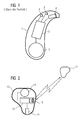
- the amplifier is usually integrated in a signal processing unit. This basic structure is in FIG. 1 shown using the example of a behind-the-ear hearing aid. In a hearing aid housing 1 for Carrying behind the ear, one or more microphones 2 are installed for recording the sound from the environment.
- a signal processing unit 3 which is also integrated in the hearing aid housing 1, processes the microphone signals and amplifies them.
- the output signal of the signal processing unit 3 is transmitted to a loudspeaker or earpiece 4, which outputs an acoustic signal.
- the sound is optionally transmitted via a sound tube, which is fixed with an earmold in the ear canal, to the eardrum of the device carrier.
- the power supply of the hearing device and in particular of the signal processing unit 3 is carried out by a likewise integrated into the hearing aid housing 1 battery. 5
- PDM pulse density modulation
- PWM pulse width modulation
- the digital control has the advantage that in digital hearing aids, the level of the digital-to-analog converter can be omitted.
- Digital drive circuits also have a significantly higher efficiency than analog drive circuits.
- analog drive circuits are less noisy, i. they prove a limited to the acoustic signal frequency spectrum with a low harmonic content.
- the high levels of harmonic distortion associated with digital control interfere with wireless transmission of data between hearing aids and transmission between a hearing aid and external accessories (remote control, wireless programmer, wireless relay, etc.).
- the object of the present invention is thus, in particular for digitally operating hearing a to enable power-saving digital control of the loudspeaker of the hearing device.
- a corresponding method for operating a hearing device is to be provided.
- this object is achieved by a hearing device with a transmission device for wireless data transmission in a main frequency band, a loudspeaker and a control device for driving the loudspeaker with a control signal, wherein the frequency spectrum of the control signal has a significant incision in a region of the main frequency band.
- the invention provides a method for operating a hearing device by wireless data transmission in a main frequency band and driving a loudspeaker of the hearing device with a drive signal, wherein the frequency spectrum of the drive signal in a region of the main frequency band has a significant incision.
- the drive signal of the drive device is pulse density modulated or pulse width modulated. This makes it possible to control a low-pass inductive loudspeaker without a high signal processing effort of a digital signal processing circuit.
- the data transmission by the transmission device can be broadband in a plurality of frequency bands, and the frequency spectrum of the drive signal can each have a significant incision in the region of each of the frequency bands.
- the inventive principle can also be used for a broadband transmission of high data rate.
- the transmission device can have a bandpass filter which essentially allows only frequency components which lie in the main frequency band or in the main frequency band and in the range of many of them to pass. As a result, the interference immunity of the wireless transmission can be additionally increased.
- the hearing device according to the invention can be configured in a special embodiment as in-the-ear hearing aid, even if the power consumption and the space available there are extremely limited. Because of the small amount of space available, the handset, which is usually a magnetoacoustic transducer, is very close to the receiver coil. In addition, with in-the-ear hearing aids, the position and orientation of each device is unique. In any case, the listener induces more or less large interference in the receiver coil. As a result, the signal-to-noise ratio is generally significantly worsened there. The poor signal-to-noise ratio could be improved by an increased transmission power, but this can only be achieved by an enormous energy demand. Therefore, the solution according to the invention is all the more welcome to spectrally separate the drive signal for the listener from the transmission signal for wireless data transmission.
- a hearing system with two hearing aids is provided according to the invention, each having the structure of the hearing device described above, the transmission facilities of both hearing aids allow bidirectional, wireless data transmission, and a data transmission in one direction in another frequency band than a data transmission in the other direction.
- the transmission facilities of both hearing aids allow bidirectional, wireless data transmission, and a data transmission in one direction in another frequency band than a data transmission in the other direction.
- FIG. 2 is a hearing aid system with two hearing aids 10 and 11 shown schematically.
- the two hearing aids 10, 11 have the same structure. For clarity, however, only in the hearing aid 10, the essential components for the present invention are shown.
- the central unit of the ITE hearing aid 10 is a signal processing or control unit 12. It is powered by a battery 13. Its output signal is used to control a receiver 14, which is usually designed as a magnetoacoustic transducer.
- the control unit 12 also controls a transmission unit 15, which serves here for bidirectional transmission to the second hearing device 11.
- the transmission device 15 is symbolized by a coil, but it may also contain other transmission components.
- FIG. 2 It can be seen that the electronic components are arranged in the ITE hearing aid 10 spatially very close to each other.
- the handset 14 and the transmission unit 15 are placed very close together, so that there is an involuntary mutual interference and interference.
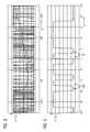
- FIG. 3 shows a typical PDM drive signal with which the drive unit 12 timed the handset 14.
- the information to be transmitted to the listener is in the pulse density.
- FIG. 4 a section of this signal is reproduced in an enlarged view. The density of the pulses varies in the desired manner.
- the handset 14 has a specific inductive characteristic. Therefore, the leads in FIG. 3 reproduced time PDM voltage signal in the handset to the dashed lines in the FIG drawn current waveform.
- the frequency spectrum of the PDM voltage signal of FIG. 3 is in FIG. 5 shown. It consists essentially of arcs that are periodically lined up and whose amplitude decreases due to the rectangular shape of the PDM pulses according to the function sin x / x. In certain areas of the spectrum, namely between two arcs, incisions E are produced in the spectrum, ie so-called "vacated areas". In these vacated areas so no or hardly any interference occurs. There then only the useful signal N or Nutzsignalanmaschine N 'are present. The emergence of the incisions E, which are also referred to as "notches" can be explained as follows: The pulse durations Tp of the PDM signal are fixed and occur in a fixed time grid of nx Tp.
- the basic idea of the present invention is now to adapt the operating frequency of the digital receiver control to the wireless transmission system. Specifically, therefore, it is attempted to remove interfering receiver noise components from the used frequency band for wireless data transmission. This is achieved here by the appropriate favorable shaping of the interference spectrum ("noise-shaping") by the operating frequency of the PDM modulator is just chosen so that the incisions E are in the range of transmission frequency for the wireless transmission or their multiples. Thus, the wireless transmission is only slightly affected and the benefits of digital handset control remain.
- noise components from the frequency ranges used for the wireless data transmission can be supplemented by further known "noise-shaping" methods.
- noise components from the low-frequency range of the audio signals can be pushed in a known manner in the direction of higher frequencies.
- the width and the shape of the incisions can be optimized in each case or "notches".
- the immunity to interference of the wireless transmission against the handset control can be further improved by performing the signal processing of the wireless transmission part with a band-pass filter that only allows frequencies within the wireless bandwidth to pass unhindered.
- the filter function F of such a bandpass filter is in FIG. 6 represented together with the PDM frequency spectrum of the example signal.
- the improvement of immunity to interference is particularly effective if the characteristics of the bandpass filter (slope of the filter edges, quality of the filter) and the characteristic of the "noise-shaping" are adapted to each other.
- notches In the example of FIG. 5 occur at fixed frequency intervals "notches". In the simplest case, only one of them is used for wireless data transmission. However, for high-bandwidth applications, wireless transmission may be split into multiple sub-frequency ranges. Then the sub-frequency ranges should be in the other "notches" of the PDM drive signal to the listener. With regard to the immunity to disturbance, the characteristics of the bandpass and of the "noise-shaping" should also be adapted to each other. This can be achieved, for example, with special comb filters whose passband are matched to the "notches".
Landscapes
- Engineering & Computer Science (AREA)
- Health & Medical Sciences (AREA)
- General Health & Medical Sciences (AREA)
- Neurosurgery (AREA)
- Otolaryngology (AREA)
- Physics & Mathematics (AREA)
- Acoustics & Sound (AREA)
- Signal Processing (AREA)
- Computer Networks & Wireless Communication (AREA)
- Circuit For Audible Band Transducer (AREA)
- Transceivers (AREA)
Abstract
Description
- Die vorliegende Erfindung betrifft eine Hörvorrichtung mit einer Übertragungseinheit zur drahtlosen Datenübertragung in einem Hauptfrequenzband, einem Lautsprecher und einer Ansteuereinrichtung zum Ansteuern des Lautsprechers mit einem Ansteuersignal. Darüber hinaus betrifft die vorliegende Erfindung ein entsprechendes Verfahren zum Betreiben einer Hörvorrichtung. Unter dem Begriff "Hörvorrichtung" wird hier insbesondere ein Hörgerät, ein Headset, Kopfhörer und andere am Kopf tragbare Geräte verstanden.
- Hörgeräte sind tragbare Hörvorrichtungen, die zur Versorgung von Schwerhörenden dienen. Um den zahlreichen individuellen Bedürfnissen entgegenzukommen, werden unterschiedliche Bauformen von Hörgeräten wie Hinter-dem-Ohr-Hörgeräte (HdO) und In-dem-Ohr-Hörgeräte (IdO), z.B. auch Concha-Hörgeräte oder Kanal-Hörgeräte (CIC), bereitgestellt. Die beispielhaft aufgeführten Hörgeräte werden am Außenohr oder im Gehörgang getragen. Darüber hinaus stehen auf dem Markt aber auch Knochenleitungshörhilfen, implantierbare oder vibrotaktile Hörhilfen zur Verfügung. Dabei erfolgt die Stimulation des geschädigten Gehörs entweder mechanisch oder elektrisch.
- Hörgeräte besitzen prinzipiell als wesentliche Komponenten einen Eingangswandler, einen Verstärker und einen Ausgangswandler. Der Eingangswandler ist in der Regel ein Schallempfänger, z. B. ein Mikrofon, und/oder ein elektromagnetischer Empfänger, z. B. eine Induktionsspule. Der Ausgangswandler ist meist als elektroakustischer Wandler, z. B. Miniaturlautsprecher, oder als elektromechanischer Wandler, z. B. Knochenleitungshörer, realisiert. Der Verstärker ist üblicherweise in eine Signalverarbeitungseinheit integriert. Dieser prinzipielle Aufbau ist in
FIG 1 am Beispiel eines Hinter-dem-Ohr-Hörgeräts dargestellt. In ein Hörgerätegehäuse 1 zum Tragen hinter dem Ohr sind ein oder mehrere Mikrofone 2 zur Aufnahme des Schalls aus der Umgebung eingebaut. Eine Signalverarbeitungseinheit 3, die ebenfalls in das Hörgerätegehäuse 1 integriert ist, verarbeitet die Mikrofonsignale und verstärkt sie. Das Ausgangssignal der Signalverarbeitungseinheit 3 wird an einen Lautsprecher bzw. Hörer 4 übertragen, der ein akustisches Signal ausgibt. Der Schall wird gegebenenfalls über einen Schallschlauch, der mit einer Otoplastik im Gehörgang fixiert ist, zum Trommelfell des Geräteträgers übertragen. Die Stromversorgung des Hörgeräts und insbesondere die der Signalverarbeitungseinheit 3 erfolgt durch eine ebenfalls ins Hörgerätegehäuse 1 integrierte Batterie 5. - Zur Ansteuerung des Lautsprechers bzw. Hörers eines Hörgeräts wird häufig beispielsweise die Pulsdichtemodulation (PDM) oder Pulsweitenmodulation (PWM) eingesetzt. Die digitale Ansteuerung besitzt den Vorteil, dass bei digitalen Hörgeräten die Stufe des Digital-analog-Wandlers entfallen kann. Digitale Ansteuerschaltungen haben ferner einen deutlich höheren Wirkungsgrad als analoge Ansteuerschaltungen. Dagegen sind analoge Ansteuerschaltungen störärmer, d.h. sie belegen ein auf das akustische Signal begrenztes Frequenzspektrum mit geringem Oberwellenanteil. Die bei digitaler Ansteuerung sehr stark ausgeprägten Oberwellen stören jedoch die drahtlose Übertragung von Daten zwischen Hörgeräten und die Übertragung zwischen einem Hörgerät und externem Zubehör (Fernbedienung, drahtloses Programmiergerät, drahtloses Relaisgerät, etc.).
- Eine mögliche Lösung dieses Problems könnte in dem folgenden Kompromiss liegen: Der Hörer wird bei Hörgeräten mit drahtloser Übertragung analog angesteuert und bei Hörgeräten ohne Drahtlos-Funktion erfolgt eine stromsparende digitale Ansteuerung. Damit könnten jedoch Hörgeräte mit drahtloser Übertragung von der stromsparenden digitalen Ansteuerung nicht profitieren.
- Die Aufgabe der vorliegenden Erfindung besteht somit darin, insbesondere auch für digital arbeitende Hörvorrichtungen eine stromsparende digitale Ansteuerung des Lautsprechers der Hörvorrichtung zu ermöglichen. Darüber hinaus soll ein entsprechendes Verfahren zum Betreiben einer Hörvorrichtung bereitgestellt werden.
- Erfindungsgemäß wird diese Aufgabe gelöst durch eine Hörvorrichtung mit einer Übertragungseinrichtung zur drahtlosen Datenübertragung in einem Hauptfrequenzband, einem Lautsprecher und einer Ansteuereinrichtung zum Ansteuern des Lautsprechers mit einem Ansteuersignal, wobei das Frequenzspektrum des Ansteuersignals in einem Bereich des Hauptfrequenzbands einen wesentlichen Einschnitt besitzt.
- Darüber hinaus wird erfindungsgemäß bereitgestellt ein Verfahren zum Betreiben einer Hörvorrichtung durch drahtloses Datenübertragen in einem Hauptfrequenzband und Ansteuern eines Lautsprechers der Hörvorrichtung mit einem Ansteuersignal, wobei das Frequenzspektrum des Ansteuersignals in einem Bereich des Hauptfrequenzbands einen wesentlichen Einschnitt besitzt.
- Durch die Trennung der Signale für die Datenübertragung und für die Ansteuerung des Lautsprechers im Frequenzbereich treten kaum mehr wechselseitige Störungen auf, so dass auch eine Hörvorrichtung, die zur drahtlosen Datenübertragung ausgelegt ist, den internen Hörer bzw. Lautsprecher digital ansteuern kann.
- Vorzugsweise ist das Ansteuersignal der Ansteuereinrichtung pulsdichtemoduliert oder pulsweitenmoduliert. Damit lässt sich ein als Tiefpass wirkender induktiver Lautsprecher ohne hohen Signalverarbeitungsaufwand von einer digitalen Signalverarbeitungsschaltung ansteuern.
- Die Datenübertragung durch die Übertragungseinrichtung kann breitbandig in mehreren Frequenzbändern erfolgen, und das Frequenzspektrum des Ansteuersignals kann im Bereich jedes der Frequenzbänder jeweils einen wesentlichen Einschnitt aufweisen. Damit ist das erfindungsgemäße Prinzip auch für eine breitbandige Übertragung hoher Datenrate einsetzbar.
- Des Weiteren kann die Übertragungseinrichtung ein Bandpassfilter aufweisen, das im Wesentlichen nur Frequenzanteile passieren lässt, welche im Hauptfrequenzband oder im Hauptfrequenzband und im Bereich Vielfacher davon liegen. Dadurch kann die Störfestigkeit der drahtlosen Übertragung zusätzlich gesteigert werden.
- Die erfindungsgemäße Hörvorrichtung kann in einer speziellen Ausführungsform als In-dem-Ohr-Hörgerät ausgestaltet sein, auch wenn dort der Stromverbrauch und der zur Verfügung stehende Platz äußerst beschränkt sind. Durch das geringe Platzangebot befindet sich nämlich der Hörer, der in der Regeln ein magnetoakustischer Wandler ist, sehr nahe an der Empfangsspule. Darüber hinaus ist bei In-dem-Ohr-Hörgeräten die Position und die Ausrichtung bei jedem Gerät individuell. In jedem Fall induziert der Hörer mehr oder weniger große Störsignale in der Empfangsspule. Damit wird dort das Signal-zu-Rausch-Verhältnis in der Regel deutlich verschlechtert. Das schlechte Signal-zu-Rausch-Verhältnis könnte durch eine erhöhte Sendeleistung verbessert werden, was aber nur durch einen enormen Energiebedarf zu erreichen ist. Um so willkommener ist daher die erfindungsgemäße Lösung, das Ansteuersignal für den Hörer spektral von dem Übertragungssignal für die drahtlose Datenübertragung zu trennen.
- Entsprechend einer weiteren Ausführungsform wird erfindungsgemäß ein Hörsystem mit zwei Hörgeräten bereitgestellt, die jeweils den Aufbau der oben beschriebenen Hörvorrichtung besitzen, wobei die Übertragungseinrichtungen beider Hörgeräte eine bidirektionale, drahtlose Datenübertragung ermöglichen, und eine Datenübertragung in einer Richtung in einem anderen Frequenzband erfolgt als eine Datenübertragung in der anderen Richtung. Damit kann eine echte bidirektionale Verbindung mit zeitgleichen direktionalen Übertragungen zur Verfügung gestellt werden.
- Die vorliegende Erfindung ist anhand der beigefügten Zeichnungen näher erläutert, in denen zeigen:
- FIG 1
- den prinzipiellen Aufbau eines Hörgeräts gemäß dem Stand der Technik;
- FIG 2
- ein erfindungsgemäßes Hörgerätesystem;
- FIG 3
- ein PDM-Zeitsignal der Spannung am Hörer;
- FIG 4
- einen vergrößerten Ausschnitt des PDM-Zeitsignals von
FIG 3 ; - FIG 5
- das PDM-Frequenzspektrum des Signals von
FIG 3 und - FIG 6
- das PDM-Frequenzspektrum von
FIG 5 zusammen mit einer Durchlasskurve eines ideal angepassten Frequenzfilters. - Die nachfolgend geschilderten Ausführungsbeispiele stellen bevorzugte Ausführungsformen der vorliegenden Erfindung dar.
- In
FIG 2 ist ein Hörgerätesystem mit zwei Hörgeräten 10 und 11 schematisch dargestellt. Die beiden Hörgeräte 10, 11 sind gleich aufgebaut. Der Übersicht halber sind jedoch nur in dem Hörgerät 10 die für die vorliegende Erfindung wesentlichen Komponenten dargestellt. Die zentrale Einheit des IdO-Hörgeräts 10 ist eine Signalverarbeitungs- bzw. Steuereinheit 12. Sie wird von einer Batterie 13 versorgt. Ihr Ausgangssignal dient zur Ansteuerung eines Hörers 14, der in der Regel als magnetoakustischer Wandler ausgebildet ist. Darüber hinaus steuert die Steuereinheit 12 auch eine Übertragungseinheit 15 an, die hier zur bidirektionalen Übertragung zu dem zweiten Hörgerät 11 dient. Die Übertragungseinrichtung 15 ist durch eine Spule symbolisiert, sie kann aber auch andere Übertragungskomponenten enthalten. - Aus
FIG 2 ist ersichtlich, dass die Elektronikkomponenten in dem IdO-Hörgerät 10 räumlich sehr nahe aneinander angeordnet sind. Insbesondere sind auch der Hörer 14 und die Übertragungseinheit 15 sehr nahe beisammen platziert, so dass es unwillkürlich zu gegenseitigen Beeinflussungen und Störungen kommt. -
FIG 3 zeigt ein typisches PDM-Ansteuersignal, mit dem die Ansteuereinheit 12 den Hörer 14 zeitlich ansteuert. Die an den Hörer zu übertragende Information steckt in der Pulsdichte. InFIG 4 ist ein Ausschnitt dieses Signals in vergrößerter Darstellung wiedergegeben. Die Dichte der Impulse variiert in der gewünschten Weise. - Der Hörer 14 besitzt eine spezifische induktive Charakteristik. Daher führt das in
FIG 3 wiedergegebene zeitliche PDM-Spannungssignal im Hörer zu dem in der FIG gestrichelt eingezeichneten Stromverlauf. - Das Frequenzspektrum des PDM-Spannungssignals von
FIG 3 ist inFIG 5 dargestellt. Es besteht im Wesentlichen aus Bögen, die periodisch aneinander gereiht sind und deren Amplitude aufgrund der Rechteckform der PDM-Impulse entsprechend der Funktion sin x/x abnehmen. In bestimmten Bereichen des Spektrums, nämlich zwischen zwei Bögen ergeben sich im Spektrum Einschnitte E, d.h. sogenannte "frei geräumte Bereiche". In diesen frei geräumten Bereichen treten also keine bzw. kaum Störsignale auf. Dort sind dann nur das Nutzsignal N bzw. Nutzsignalanteile N' vorhanden. Das Entstehen der Einschnitte E, die auch als "notches" bezeichnet werden, kann wie folgt erklärt werden: Die Pulsdauern Tp des PDM-Signals sind fest gewählt und treten in einem festen Zeitraster von n x Tp auf. Die statistische Verteilung von positiven und negativen Pulsen ist für natürliche Audiosignale gleich. Dadurch tritt die Frequenz 1/(2Tp) sowie deren ganzzahlige Vielfache mit etwa gleicher Amplitude in der Phasenlage 0° und 180° auf. Dies führt zu der gezielten Auslöschung von Signalen im Bereich um die Frequenzen n x 1/(2Tp). Diese Auslöschung führt zu den oben erwähnten Einschnitten E bzw. "notches". Dazwischen ergeben sich die bogenförmigen Störsignalanteile S. - Die Grundidee der vorliegenden Erfindung besteht nun in der Anpassung der Arbeitsfrequenz der digitalen Höreransteuerung an das drahtlose Übertragungssystem. Konkret wird also versucht, störende Hörer-Rauschanteile aus dem genutzten Frequenzband für die drahtlose Datenübertragung zu entfernen. Dies wird hier durch die entsprechende günstige Formung des Störspektrums ("Noise-shaping") erreicht, indem die Arbeitsfrequenz des PDM-Modulators eben so gewählt wird, dass die Einschnitte E im Bereich der Übertragungsfrequenz für die drahtlose Übertragung bzw. deren Vielfache liegen. Damit wird die drahtlose Übertragung nur noch geringfügig beeinträchtigt und die Vorteile der digitalen Höreransteuerung bleiben bestehen.
- Das Freiräumen von Störanteilen aus den für die drahtlose Datenübertragung genutzten Frequenzbereichen kann durch weitere bekannte "Noise-shaping"-Verfahren ergänzt werden. So können beispielsweise Rauschanteile aus dem niederfrequenten Bereich der Audiosignale auf bekannte Weise in Richtung höherer Frequenzen geschoben werden. Mit diesem und anderen bekannten Verfahren lassen sich so die Breite und die Form der Einschnitte je bzw. "notches" optimieren.
- Die Störfestigkeit der drahtlosen Übertragung gegen die Höreransteuerung kann weiter verbessert werden, indem die Signalverarbeitung des drahtlosen Übertragungsteils mit einem Bandpassfilter ausgeführt wird, das nur Frequenzen innerhalb der drahtlos genutzten Bandbreite ungehindert durchlässt. Die Filterfunktion F eines derartigen Bandpassfilters ist in
FIG 6 zusammen mit dem PDM-Frequenzspektrum des Beispielsignals dargestellt. Besonders effektiv ist die Verbesserung der Störfestigkeit, wenn die Charakteristik des Bandpasses (Steigung der Filterflanken, Güte des Filters) und die Charakteristik des "Noise-shaping" aufeinander angepasst sind. - In dem Beispiel von
FIG 5 treten in festen Frequenzabständen "notches" auf. Im einfachsten Fall wird nur einer davon für die drahtlose Datenübertragung genutzt. Für Anwendungen mit großem Bandbreitenbedarf kann die drahtlose Übertragung aber auch auf mehrere Teilfrequenzbereiche aufgeteilt werden. Dann sollten die Teilfrequenzbereiche in den anderen "notches" des PDM-Ansteuersignals für den Hörer liegen. Hinsichtlich der Störfestigkeit sollte auch hier die Charakteristik des Bandpasses und die des "Noise-shaping" aneinander angepasst sein. Dies lässt sich beispielsweise mit speziellen Kammfiltern erreichen, deren Durchlassbereich auf die "notches" abgestimmt sind. - Nach dem Filtern erhält man einen flachen, niedrigen Grundrauschpegel, aus dem auch kleine Nutzsignale noch gut detektierbar sind. Als Folge steigt die mögliche Reichweite der drahtlosen Übertragung. Alternativ kann bei gleicher Reichweite eine höhere Datenrate erzielt werden.
- Oben wurde bereits angedeutet, dass für Anwendungen, in denen mehrere Frequenzbereiche genutzt werden, bandbreitenintensive Übertragungen von Audiosignalen oder Programmierdaten möglich sind. Gegebenenfalls können mehrere Frequenzbänder aber auch für zeitgleiche bidirektionale Übertragungen genutzt werden, indem die Richtungen auf unterschiedliche Frequenzbereiche aufgeteilt werden.
Claims (10)
- Hörvorrichtung (10) mit- einer Übertragungseinrichtung (15) zur drahtlosen Datenübertragung in einem Hauptfrequenzband,- einem Lautsprecher (14) und- einer Ansteuereinrichtung (12) zum Ansteuern des Lautsprechers (14) mit einem Ansteuersignal,dadurch gekennzeichnet, dass- das Frequenzspektrum des Ansteuersignals in einem Bereich des Hauptfrequenzbands einen wesentlichen Einschnitt besitzt.
- Hörvorrichtung nach Anspruch 1, wobei das Ansteuersignal der Ansteuereinrichtung (12) pulsdichtemoduliert ist.
- Hörvorrichtung nach Anspruch 1 oder 2, wobei die Datenübertragung durch die Übertragungseinrichtung (15) breitbandig in mehreren Frequenzbändern erfolgt und das Frequenzspektrum des Ansteuersignals im Bereich jedes der Frequenzbänder jeweils einen wesentlichen Einschnitt aufweist.
- Hörvorrichtung nach einem der vorhergehenden Ansprüche, wobei die Übertragungseinrichtung (15) ein Bandpassfilter aufweist, das im Wesentlichen nur Frequenzanteile passieren lässt, welche im Hauptfrequenzband oder im Hauptfrequenzband und im Bereich Vielfacher davon liegen.
- Hörvorrichtung nach einem der vorhergehenden Ansprüche, die als In-dem-Ohr-Hörgerät ausgestaltet ist.
- Hörsystem mit zwei Hörgeräten (10, 11), die jeweils in Aufbau einer Hörvorrichtung nach einem der Ansprüche 3 bis 5 besitzen, wobei die Übertragungseinrichtungen (15) beider Hörgeräte (10, 11) eine bidirektionale, drahtlose Datenübertragung ermöglichen, und eine Datenübertragung in einer Richtung in einem anderen Frequenzband erfolgt, als eine Datenübertragung in der anderen Richtung.
- Verfahren zum Betreiben einer Hörvorrichtung (10, 11) durch- drahtloses Datenübertragen in einem Hauptfrequenzband und- Ansteuern eines Lautsprechers (14) der Hörvorrichtung mit einem Ansteuersignal,dadurch gekennzeichnet, dass- das Frequenzspektrum des Ansteuersignals in einem Bereich des Hauptfrequenzbands einen wesentlichen Einschnitt (E) besitzt.
- Verfahren nach Anspruch 7, wobei das Ansteuersignal pulsdichtemoduliert ist.
- Verfahren nach Anspruch 7 oder 8, wobei die Datenübertragung breitbandig in mehreren Frequenzbändern erfolgt und das Frequenzspektrum des Ansteuersignals im Bereich jedes der Frequenzbänder jeweils einen wesentlichen Einschnitt (E) aufweist.
- Verfahren nach einem der Ansprüche 7 bis 9, wobei das Signal zur Datenübertragung mit einem Bandpass gefiltert wird, das im Wesentlichen nur Frequenzanteile passieren lässt, welche im Hauptfrequenzband oder im Hauptfrequenzband und im Bereich Vielfacher davon liegen.
Applications Claiming Priority (1)
| Application Number | Priority Date | Filing Date | Title |
|---|---|---|---|
| DE200710018121 DE102007018121B4 (de) | 2007-04-16 | 2007-04-16 | Hörvorrichtung mit störarmer Höreransteuerung und entsprechendes Verfahren sowie Hörsystem |
Publications (3)
| Publication Number | Publication Date |
|---|---|
| EP1983800A2 true EP1983800A2 (de) | 2008-10-22 |
| EP1983800A3 EP1983800A3 (de) | 2009-10-28 |
| EP1983800B1 EP1983800B1 (de) | 2016-12-14 |
Family
ID=39535305
Family Applications (1)
| Application Number | Title | Priority Date | Filing Date |
|---|---|---|---|
| EP08103047.0A Active EP1983800B1 (de) | 2007-04-16 | 2008-03-28 | Hörvorrichtung mit störarmer höreransteuerung und entsprechendes verfahren |
Country Status (6)
| Country | Link |
|---|---|
| EP (1) | EP1983800B1 (de) |
| JP (1) | JP5322485B2 (de) |
| CN (1) | CN101312602B (de) |
| AU (1) | AU2008201690B2 (de) |
| DE (1) | DE102007018121B4 (de) |
| DK (1) | DK1983800T3 (de) |
Families Citing this family (5)
| Publication number | Priority date | Publication date | Assignee | Title |
|---|---|---|---|---|
| AU2010225449A1 (en) * | 2009-03-16 | 2011-10-13 | Cochlear Limited | Transcutaneous modulated power link for a medical implant |
| DE102010039303A1 (de) * | 2010-08-13 | 2012-02-16 | Siemens Medical Instruments Pte. Ltd. | Verfahren zum Reduzieren von Interferenzen und Hörvorrichtung |
| DE102021200642B3 (de) | 2021-01-25 | 2022-03-17 | Sivantos Pte. Ltd. | Hörgerät |
| CN113081765B (zh) * | 2021-04-15 | 2022-06-07 | 四川千里倍益康医疗科技股份有限公司 | 电动按摩器及其基于pwm的骨骼识别方法 |
| WO2024004925A1 (ja) * | 2022-06-28 | 2024-01-04 | ピクシーダストテクノロジーズ株式会社 | 信号処理装置、マイク付きイヤホン、信号処理方法、およびプログラム |
Citations (2)
| Publication number | Priority date | Publication date | Assignee | Title |
|---|---|---|---|---|
| US20040109577A1 (en) | 2002-09-30 | 2004-06-10 | Kunibert Husung | Hearing aid device or hearing device system with a clock generator |
| US20060104463A1 (en) | 2004-11-12 | 2006-05-18 | Hans-Ueli Roeck | Storsignalfilter in horgeraten |
Family Cites Families (9)
| Publication number | Priority date | Publication date | Assignee | Title |
|---|---|---|---|---|
| CA2212131A1 (en) * | 1996-08-07 | 1998-02-07 | Beltone Electronics Corporation | Digital hearing aid system |
| JP2904272B2 (ja) * | 1996-12-10 | 1999-06-14 | 日本電気株式会社 | ディジタル補聴器、及びその補聴処理方法 |
| US6605991B2 (en) * | 2001-08-30 | 2003-08-12 | Motorola, Inc. | Circuitry for creating a spectral null in a differential output switching amplifier and method therefor |
| DE10304648B3 (de) * | 2003-02-05 | 2004-08-19 | Siemens Audiologische Technik Gmbh | Vorrichtung und Verfahren zur Kommunikation von Hörgeräten |
| US7289568B2 (en) * | 2003-11-19 | 2007-10-30 | Intel Corporation | Spectrum management apparatus, method, and system |
| JP2008504566A (ja) * | 2004-06-28 | 2008-02-14 | コーニンクレッカ フィリップス エレクトロニクス エヌ ヴィ | 音響送信装置、音響受信装置、周波数範囲適応装置、音響信号送信方法 |
| CN101124849B (zh) * | 2005-01-17 | 2012-07-04 | 唯听助听器公司 | 用于操作助听器的装置和方法 |
| JP2006217088A (ja) * | 2005-02-01 | 2006-08-17 | Sharp Corp | 聴覚伝送システム |
| DK1860914T3 (da) * | 2006-05-24 | 2009-03-30 | Phonak Ag | System til hörehjælp og fremgangsmåde til drift af dette |
-
2007
- 2007-04-16 DE DE200710018121 patent/DE102007018121B4/de active Active
-
2008
- 2008-03-28 EP EP08103047.0A patent/EP1983800B1/de active Active
- 2008-03-28 DK DK08103047.0T patent/DK1983800T3/da active
- 2008-04-15 JP JP2008105561A patent/JP5322485B2/ja not_active Expired - Fee Related
- 2008-04-16 CN CN2008101314532A patent/CN101312602B/zh active Active
- 2008-04-16 AU AU2008201690A patent/AU2008201690B2/en not_active Ceased
Patent Citations (2)
| Publication number | Priority date | Publication date | Assignee | Title |
|---|---|---|---|---|
| US20040109577A1 (en) | 2002-09-30 | 2004-06-10 | Kunibert Husung | Hearing aid device or hearing device system with a clock generator |
| US20060104463A1 (en) | 2004-11-12 | 2006-05-18 | Hans-Ueli Roeck | Storsignalfilter in horgeraten |
Also Published As
| Publication number | Publication date |
|---|---|
| DK1983800T3 (da) | 2017-03-27 |
| DE102007018121B4 (de) | 2012-12-06 |
| JP5322485B2 (ja) | 2013-10-23 |
| EP1983800B1 (de) | 2016-12-14 |
| CN101312602B (zh) | 2012-04-25 |
| AU2008201690A1 (en) | 2008-10-30 |
| JP2008271549A (ja) | 2008-11-06 |
| AU2008201690B2 (en) | 2010-01-28 |
| DE102007018121A1 (de) | 2008-10-30 |
| CN101312602A (zh) | 2008-11-26 |
| EP1983800A3 (de) | 2009-10-28 |
Similar Documents
| Publication | Publication Date | Title |
|---|---|---|
| EP0071845B1 (de) | Gerät zur Kompensation von Gehörschäden | |
| EP2124334B1 (de) | Filterbanksystem für Hörgeräte | |
| EP0793897A1 (de) | Hörhilfsgerät | |
| EP2645743B1 (de) | Hörvorrichtung für eine binaurale Versorgung und Verfahren zum Bereitstellen einer binauralen Versorgung | |
| EP2437258B1 (de) | Verfahren und Vorrichtung zur Frequenzkompression mit selektiver Frequenzverschiebung | |
| EP1983800B1 (de) | Hörvorrichtung mit störarmer höreransteuerung und entsprechendes verfahren | |
| EP2124335B1 (de) | Verfahren zum Optimieren einer mehrstufigen Filterbank sowie entsprechende Filterbank und Hörvorrichtung | |
| EP2124482B1 (de) | Hörvorrichtung mit einem Entzerrungsfilter im Filterbank-System | |
| EP1945000B1 (de) | Verfahren zur Reduktion von Störleistungen und entsprechendes Akustiksystem | |
| EP1725072A2 (de) | Hörhilfevorrichtung mit zwei unterschiedlichen Ausgangswandlern und Anpassverfahren | |
| EP2437521B1 (de) | Verfahren zur Frequenzkompression mit harmonischer Korrektur und entsprechende Vorrichtung | |
| EP2629550B1 (de) | Hörvorrichtung mit einem adaptiven Filter und Verfahren zum Filtern eines Audiosignals | |
| DE102005006858A1 (de) | Hörhilfegerät mit einem Ausgangsverstärker, der einen Sigma-Delta-Modulator umfasst | |
| EP2190218B1 (de) | Filterbanksystem mit spezifischen Sperrdämpfungsanteilen für eine Hörvorrichtung | |
| EP1909535B1 (de) | Hörvorrichtung mit gesteuerten Eingangskanälen und entsprechendes Verfahren | |
| EP2418876A1 (de) | Verfahren zum Reduzieren von Interferenzen und Hörvorrichtung | |
| DE102007010601A1 (de) | Hörsystem mit verteilter Signalverarbeitung und entsprechendes Verfahren | |
| EP1909534A2 (de) | Hörvorrichtung mit unsymmetrischer Klangwaage und entsprechendes Einstellverfahren | |
| EP4478743A1 (de) | Verfahren zum betrieb eines hörgeräts und hörgerät | |
| WO2012041372A1 (de) | Verfahren zur frequenzkompression, anpasseinrichtung und hörvorrichtung | |
| DE102023211025A1 (de) | Verfahren zum Betreiben einer Antennenanordnung | |
| DE102012206299B4 (de) | Verfahren zum Betreiben einer Hörvorrichtung und Hörvorrichtung | |
| EP2622879B1 (de) | Verfahren und vorrichtung zur frequenzkompression | |
| EP1330939A2 (de) | Verfahren zur steuerung des dynamikbereiches eines hörgerätes sowie verfahren zur fertigung von hörgerätetypen und hörgerät | |
| EP1052830A2 (de) | Mobilfunk-Endgerät |
Legal Events
| Date | Code | Title | Description |
|---|---|---|---|
| PUAI | Public reference made under article 153(3) epc to a published international application that has entered the european phase |
Free format text: ORIGINAL CODE: 0009012 |
|
| AK | Designated contracting states |
Kind code of ref document: A2 Designated state(s): AT BE BG CH CY CZ DE DK EE ES FI FR GB GR HR HU IE IS IT LI LT LU LV MC MT NL NO PL PT RO SE SI SK TR |
|
| AX | Request for extension of the european patent |
Extension state: AL BA MK RS |
|
| PUAL | Search report despatched |
Free format text: ORIGINAL CODE: 0009013 |
|
| AK | Designated contracting states |
Kind code of ref document: A3 Designated state(s): AT BE BG CH CY CZ DE DK EE ES FI FR GB GR HR HU IE IS IT LI LT LU LV MC MT NL NO PL PT RO SE SI SK TR |
|
| AX | Request for extension of the european patent |
Extension state: AL BA MK RS |
|
| 17P | Request for examination filed |
Effective date: 20091019 |
|
| AKX | Designation fees paid |
Designated state(s): AT BE BG CH CY CZ DE DK EE ES FI FR GB GR HR HU IE IS IT LI LT LU LV MC MT NL NO PL PT RO SE SI SK TR |
|
| RAP1 | Party data changed (applicant data changed or rights of an application transferred) |
Owner name: SIVANTOS PTE. LTD. |
|
| GRAP | Despatch of communication of intention to grant a patent |
Free format text: ORIGINAL CODE: EPIDOSNIGR1 |
|
| INTG | Intention to grant announced |
Effective date: 20160701 |
|
| STAA | Information on the status of an ep patent application or granted ep patent |
Free format text: STATUS: GRANT OF PATENT IS INTENDED |
|
| GRAS | Grant fee paid |
Free format text: ORIGINAL CODE: EPIDOSNIGR3 |
|
| GRAA | (expected) grant |
Free format text: ORIGINAL CODE: 0009210 |
|
| STAA | Information on the status of an ep patent application or granted ep patent |
Free format text: STATUS: THE PATENT HAS BEEN GRANTED |
|
| AK | Designated contracting states |
Kind code of ref document: B1 Designated state(s): AT BE BG CH CY CZ DE DK EE ES FI FR GB GR HR HU IE IS IT LI LT LU LV MC MT NL NO PL PT RO SE SI SK TR |
|
| REG | Reference to a national code |
Ref country code: GB Ref legal event code: FG4D Free format text: NOT ENGLISH |
|
| REG | Reference to a national code |
Ref country code: CH Ref legal event code: EP |
|
| REG | Reference to a national code |
Ref country code: IE Ref legal event code: FG4D Free format text: LANGUAGE OF EP DOCUMENT: GERMAN |
|
| REG | Reference to a national code |
Ref country code: AT Ref legal event code: REF Ref document number: 854527 Country of ref document: AT Kind code of ref document: T Effective date: 20170115 |
|
| REG | Reference to a national code |
Ref country code: DE Ref legal event code: R096 Ref document number: 502008014877 Country of ref document: DE |
|
| REG | Reference to a national code |
Ref country code: CH Ref legal event code: NV Representative=s name: E. BLUM AND CO. AG PATENT- UND MARKENANWAELTE , CH |
|
| PG25 | Lapsed in a contracting state [announced via postgrant information from national office to epo] |
Ref country code: LV Free format text: LAPSE BECAUSE OF FAILURE TO SUBMIT A TRANSLATION OF THE DESCRIPTION OR TO PAY THE FEE WITHIN THE PRESCRIBED TIME-LIMIT Effective date: 20161214 |
|
| REG | Reference to a national code |
Ref country code: FR Ref legal event code: PLFP Year of fee payment: 10 |
|
| REG | Reference to a national code |
Ref country code: DK Ref legal event code: T3 Effective date: 20170321 |
|
| REG | Reference to a national code |
Ref country code: LT Ref legal event code: MG4D |
|
| REG | Reference to a national code |
Ref country code: NL Ref legal event code: MP Effective date: 20161214 |
|
| PG25 | Lapsed in a contracting state [announced via postgrant information from national office to epo] |
Ref country code: LT Free format text: LAPSE BECAUSE OF FAILURE TO SUBMIT A TRANSLATION OF THE DESCRIPTION OR TO PAY THE FEE WITHIN THE PRESCRIBED TIME-LIMIT Effective date: 20161214 Ref country code: SE Free format text: LAPSE BECAUSE OF FAILURE TO SUBMIT A TRANSLATION OF THE DESCRIPTION OR TO PAY THE FEE WITHIN THE PRESCRIBED TIME-LIMIT Effective date: 20161214 Ref country code: GR Free format text: LAPSE BECAUSE OF FAILURE TO SUBMIT A TRANSLATION OF THE DESCRIPTION OR TO PAY THE FEE WITHIN THE PRESCRIBED TIME-LIMIT Effective date: 20170315 Ref country code: NO Free format text: LAPSE BECAUSE OF FAILURE TO SUBMIT A TRANSLATION OF THE DESCRIPTION OR TO PAY THE FEE WITHIN THE PRESCRIBED TIME-LIMIT Effective date: 20170314 |
|
| PG25 | Lapsed in a contracting state [announced via postgrant information from national office to epo] |
Ref country code: HR Free format text: LAPSE BECAUSE OF FAILURE TO SUBMIT A TRANSLATION OF THE DESCRIPTION OR TO PAY THE FEE WITHIN THE PRESCRIBED TIME-LIMIT Effective date: 20161214 Ref country code: FI Free format text: LAPSE BECAUSE OF FAILURE TO SUBMIT A TRANSLATION OF THE DESCRIPTION OR TO PAY THE FEE WITHIN THE PRESCRIBED TIME-LIMIT Effective date: 20161214 |
|
| PG25 | Lapsed in a contracting state [announced via postgrant information from national office to epo] |
Ref country code: NL Free format text: LAPSE BECAUSE OF FAILURE TO SUBMIT A TRANSLATION OF THE DESCRIPTION OR TO PAY THE FEE WITHIN THE PRESCRIBED TIME-LIMIT Effective date: 20161214 |
|
| PG25 | Lapsed in a contracting state [announced via postgrant information from national office to epo] |
Ref country code: SK Free format text: LAPSE BECAUSE OF FAILURE TO SUBMIT A TRANSLATION OF THE DESCRIPTION OR TO PAY THE FEE WITHIN THE PRESCRIBED TIME-LIMIT Effective date: 20161214 Ref country code: EE Free format text: LAPSE BECAUSE OF FAILURE TO SUBMIT A TRANSLATION OF THE DESCRIPTION OR TO PAY THE FEE WITHIN THE PRESCRIBED TIME-LIMIT Effective date: 20161214 Ref country code: IS Free format text: LAPSE BECAUSE OF FAILURE TO SUBMIT A TRANSLATION OF THE DESCRIPTION OR TO PAY THE FEE WITHIN THE PRESCRIBED TIME-LIMIT Effective date: 20170414 Ref country code: RO Free format text: LAPSE BECAUSE OF FAILURE TO SUBMIT A TRANSLATION OF THE DESCRIPTION OR TO PAY THE FEE WITHIN THE PRESCRIBED TIME-LIMIT Effective date: 20161214 Ref country code: CZ Free format text: LAPSE BECAUSE OF FAILURE TO SUBMIT A TRANSLATION OF THE DESCRIPTION OR TO PAY THE FEE WITHIN THE PRESCRIBED TIME-LIMIT Effective date: 20161214 |
|
| PG25 | Lapsed in a contracting state [announced via postgrant information from national office to epo] |
Ref country code: ES Free format text: LAPSE BECAUSE OF FAILURE TO SUBMIT A TRANSLATION OF THE DESCRIPTION OR TO PAY THE FEE WITHIN THE PRESCRIBED TIME-LIMIT Effective date: 20161214 Ref country code: BG Free format text: LAPSE BECAUSE OF FAILURE TO SUBMIT A TRANSLATION OF THE DESCRIPTION OR TO PAY THE FEE WITHIN THE PRESCRIBED TIME-LIMIT Effective date: 20170314 Ref country code: IT Free format text: LAPSE BECAUSE OF FAILURE TO SUBMIT A TRANSLATION OF THE DESCRIPTION OR TO PAY THE FEE WITHIN THE PRESCRIBED TIME-LIMIT Effective date: 20161214 Ref country code: PT Free format text: LAPSE BECAUSE OF FAILURE TO SUBMIT A TRANSLATION OF THE DESCRIPTION OR TO PAY THE FEE WITHIN THE PRESCRIBED TIME-LIMIT Effective date: 20170414 Ref country code: PL Free format text: LAPSE BECAUSE OF FAILURE TO SUBMIT A TRANSLATION OF THE DESCRIPTION OR TO PAY THE FEE WITHIN THE PRESCRIBED TIME-LIMIT Effective date: 20161214 |
|
| REG | Reference to a national code |
Ref country code: DE Ref legal event code: R097 Ref document number: 502008014877 Country of ref document: DE |
|
| PLBE | No opposition filed within time limit |
Free format text: ORIGINAL CODE: 0009261 |
|
| STAA | Information on the status of an ep patent application or granted ep patent |
Free format text: STATUS: NO OPPOSITION FILED WITHIN TIME LIMIT |
|
| 26N | No opposition filed |
Effective date: 20170915 |
|
| PG25 | Lapsed in a contracting state [announced via postgrant information from national office to epo] |
Ref country code: MC Free format text: LAPSE BECAUSE OF FAILURE TO SUBMIT A TRANSLATION OF THE DESCRIPTION OR TO PAY THE FEE WITHIN THE PRESCRIBED TIME-LIMIT Effective date: 20161214 |
|
| REG | Reference to a national code |
Ref country code: IE Ref legal event code: MM4A |
|
| PG25 | Lapsed in a contracting state [announced via postgrant information from national office to epo] |
Ref country code: LU Free format text: LAPSE BECAUSE OF NON-PAYMENT OF DUE FEES Effective date: 20170328 |
|
| PG25 | Lapsed in a contracting state [announced via postgrant information from national office to epo] |
Ref country code: IE Free format text: LAPSE BECAUSE OF NON-PAYMENT OF DUE FEES Effective date: 20170328 Ref country code: SI Free format text: LAPSE BECAUSE OF FAILURE TO SUBMIT A TRANSLATION OF THE DESCRIPTION OR TO PAY THE FEE WITHIN THE PRESCRIBED TIME-LIMIT Effective date: 20161214 |
|
| REG | Reference to a national code |
Ref country code: BE Ref legal event code: MM Effective date: 20170331 |
|
| REG | Reference to a national code |
Ref country code: FR Ref legal event code: PLFP Year of fee payment: 11 |
|
| REG | Reference to a national code |
Ref country code: AT Ref legal event code: MM01 Ref document number: 854527 Country of ref document: AT Kind code of ref document: T Effective date: 20170328 |
|
| PG25 | Lapsed in a contracting state [announced via postgrant information from national office to epo] |
Ref country code: BE Free format text: LAPSE BECAUSE OF NON-PAYMENT OF DUE FEES Effective date: 20170331 |
|
| PG25 | Lapsed in a contracting state [announced via postgrant information from national office to epo] |
Ref country code: AT Free format text: LAPSE BECAUSE OF NON-PAYMENT OF DUE FEES Effective date: 20170328 |
|
| PG25 | Lapsed in a contracting state [announced via postgrant information from national office to epo] |
Ref country code: MT Free format text: LAPSE BECAUSE OF FAILURE TO SUBMIT A TRANSLATION OF THE DESCRIPTION OR TO PAY THE FEE WITHIN THE PRESCRIBED TIME-LIMIT Effective date: 20161214 |
|
| PG25 | Lapsed in a contracting state [announced via postgrant information from national office to epo] |
Ref country code: HU Free format text: LAPSE BECAUSE OF FAILURE TO SUBMIT A TRANSLATION OF THE DESCRIPTION OR TO PAY THE FEE WITHIN THE PRESCRIBED TIME-LIMIT; INVALID AB INITIO Effective date: 20080328 |
|
| PG25 | Lapsed in a contracting state [announced via postgrant information from national office to epo] |
Ref country code: CY Free format text: LAPSE BECAUSE OF NON-PAYMENT OF DUE FEES Effective date: 20161214 |
|
| PG25 | Lapsed in a contracting state [announced via postgrant information from national office to epo] |
Ref country code: TR Free format text: LAPSE BECAUSE OF FAILURE TO SUBMIT A TRANSLATION OF THE DESCRIPTION OR TO PAY THE FEE WITHIN THE PRESCRIBED TIME-LIMIT Effective date: 20161214 |
|
| PGFP | Annual fee paid to national office [announced via postgrant information from national office to epo] |
Ref country code: DK Payment date: 20250218 Year of fee payment: 18 |
|
| PGFP | Annual fee paid to national office [announced via postgrant information from national office to epo] |
Ref country code: FR Payment date: 20250218 Year of fee payment: 18 |
|
| PGFP | Annual fee paid to national office [announced via postgrant information from national office to epo] |
Ref country code: GB Payment date: 20250221 Year of fee payment: 18 |
|
| PGFP | Annual fee paid to national office [announced via postgrant information from national office to epo] |
Ref country code: CH Payment date: 20250401 Year of fee payment: 18 |
|
| PGFP | Annual fee paid to national office [announced via postgrant information from national office to epo] |
Ref country code: DE Payment date: 20260219 Year of fee payment: 19 |