EP1982942A1 - Strip coiling method - Google Patents
Strip coiling method Download PDFInfo
- Publication number
- EP1982942A1 EP1982942A1 EP08013213A EP08013213A EP1982942A1 EP 1982942 A1 EP1982942 A1 EP 1982942A1 EP 08013213 A EP08013213 A EP 08013213A EP 08013213 A EP08013213 A EP 08013213A EP 1982942 A1 EP1982942 A1 EP 1982942A1
- Authority
- EP
- European Patent Office
- Prior art keywords
- laying
- ratio
- winding
- spool
- coil
- Prior art date
- Legal status (The legal status is an assumption and is not a legal conclusion. Google has not performed a legal analysis and makes no representation as to the accuracy of the status listed.)
- Withdrawn
Links
Images


Classifications
-
- B—PERFORMING OPERATIONS; TRANSPORTING
- B65—CONVEYING; PACKING; STORING; HANDLING THIN OR FILAMENTARY MATERIAL
- B65H—HANDLING THIN OR FILAMENTARY MATERIAL, e.g. SHEETS, WEBS, CABLES
- B65H54/00—Winding, coiling, or depositing filamentary material
- B65H54/70—Other constructional features of yarn-winding machines
- B65H54/74—Driving arrangements
-
- B—PERFORMING OPERATIONS; TRANSPORTING
- B65—CONVEYING; PACKING; STORING; HANDLING THIN OR FILAMENTARY MATERIAL
- B65H—HANDLING THIN OR FILAMENTARY MATERIAL, e.g. SHEETS, WEBS, CABLES
- B65H54/00—Winding, coiling, or depositing filamentary material
- B65H54/02—Winding and traversing material on to reels, bobbins, tubes, or like package cores or formers
- B65H54/38—Arrangements for preventing ribbon winding ; Arrangements for preventing irregular edge forming, e.g. edge raising or yarn falling from the edge
- B65H54/381—Preventing ribbon winding in a precision winding apparatus, i.e. with a constant ratio between the rotational speed of the bobbin spindle and the rotational speed of the traversing device driving shaft
- B65H54/383—Preventing ribbon winding in a precision winding apparatus, i.e. with a constant ratio between the rotational speed of the bobbin spindle and the rotational speed of the traversing device driving shaft in a stepped precision winding apparatus, i.e. with a constant wind ratio in each step
-
- B—PERFORMING OPERATIONS; TRANSPORTING
- B65—CONVEYING; PACKING; STORING; HANDLING THIN OR FILAMENTARY MATERIAL
- B65H—HANDLING THIN OR FILAMENTARY MATERIAL, e.g. SHEETS, WEBS, CABLES
- B65H2701/00—Handled material; Storage means
- B65H2701/30—Handled filamentary material
- B65H2701/37—Tapes
Definitions
- the invention relates to a method for winding a continuously fed tape on a spool while rotating the spool and reciprocating the tape by means of a traversing device over the entire length of the spool at a laying angle, each time the spool diameter has increased by a bestimmmten value , the laying ratio, that is the ratio between the reel speed and the reciprocating motion (double stroke) of the traversing device, is changed stepwise.
- Such a method for winding a continuously fed tape is referred to in the art as "stepped precision winding" and is for example from the DE 41 12 768 A , of the DE 42 23 271 C1 and the EP 0 561 188 the latter gives a detailed overview of various types of coil shapes.
- the winding of the tape takes place in winding machines on cylindrical or conical coil cores, wherein the feed rate of the tape is relatively constant on the spool core, as given by the winder upstream banding machines.
- the laying angle ⁇ is set.
- a stepped precision winding is a hybrid of two basic winding methods of how the fed tape can be wound on a spool core, namely the "wild winding” and the "precision winding".
- V variable laying ratio
- An advantage of the wild winding is the simple structure of the necessary for their production winding machine, which in Fig. 3 is shown in side view and plan view. This may in the simplest case comprise a motor 10 which drives a drive roller 11, which in turn acts on the circumference of the spool 12 and drives it at a constant peripheral speed, so that the belt 19 is wound at a constant linear speed.
- the winding spindle 18 of the spool 12 may be free-running.
- the motor 10 drives a traversing mechanism 13 via a transmission gear, consisting of pulleys 15, 16 and a belt 17 running over the two pulleys, so that the traversing belt guide 14, through which the belt 19 runs, moves at a constant lifting speed (traversing stroke). and moved.
- a transmission gear consisting of pulleys 15, 16 and a belt 17 running over the two pulleys
- the precision winding in turn is characterized by a constant installation ratio over the entire growing coil diameter, which in turn means that the laying angle decreases with increasing coil diameter.
- a precision winding with a laying ratio V 35 entered as a straight line.
- the advantage of precision winding is the achievement of a coil with constant packing density of the strip material on the coil independent of the coil diameter.
- the disadvantage of the precision winding is that - starting from an initial laying angle at the beginning of winding the strip material on an empty bobbin - the laying angle with increasing bobbin diameter is ever smaller and eventually so small (it theoretically approaches zero), that the winding is unstable becomes.
- the structure of a winding machine for generating a precision winding is in Fig.
- This winder comprises a motor 20 which rotates a winding spindle 21.
- a winding spindle 21 On the winding spindle 21 is rotatably a coil core 26, on which a tape 27 is wound to form a coil 22.
- a traversing device 23 is connected via a spur gear 25 with the winding spindle 21.
- the traversing device 23 has rotational / translational means, not shown, for reciprocating the traversing belt guide 24 in traversing strokes. Due to the direct rotary drive of the winding spindle 21, the speed of the motor 20 must be steadily reduced with increasing diameter of the forming coil 22, since the réellespulende tape is fed from a banding device with a constant linear velocity.
- stepped precision winding has been proposed in the past.
- This winding method is based on the idea that the laying ratio between predefined limit diameters of a bobbin is kept constant and is gradually changed to a different value when a respective limit diameter is reached, the values of the laying ratios being chosen such that a graph of the laying ratio over the bobbin diameter is approximately follows the graph of a wild winding for a given laying angle.
- the advantage of stepped precision winding is that, on the one hand, "image windings" are avoided, since the abrupt change in the laying ratio represents a "picture disturbance measure".
- the laying angle is not much smaller than the initial laying angle even with increasing coil diameter.
- any irregularity of the coil structure can have fatal consequences that lead as the least effect to the breakage of the tape when pulling off the coil, in the worst case, the destruction of a part of the machine , Such damage is caused by imbalance on irregular coils, by vibration of the bands during peeling, which gradually alsschaukelt, etc. Furthermore, irregular coils heat quickly when pulling off the tapes and thereby lead to fatigue and weakening of the strip material, especially if it is is about stretched plastic tape.
- the present invention provides such an improved stepped precision winding method, which is characterized in that the stepwise change of the laying ratio changes it by substantially integral steps.
- the reason for unsatisfactory buildup of coils in stepped precision winding is the sudden change in the layer pattern of the tapes resulting from the stepwise change in the laying ratio, which is a discontinuity for the overall structure of the coil. In the worst case, these altered layer images accumulate and lead to the mentioned irregularities or uneven packing density.
- the layer pattern remains essentially unchanged even after the stepwise change of the laying ratio, so that a coil with an outstanding construction, ie a regular appearance and a high packing density, results.
- a gradual change in the laying ratio by substantially integral steps should be understood to mean that the fractional part of the laying ratio changes at most by 0.1, preferably at most 0.03, more preferably at most 0.01 at each change.
- each time the ratio is changed the fractional part of this ratio is changed to the extent that there is a constant partial coverage with an underlying band track, as will be explained below with reference to an example. This achieves a very stable coil construction.
- laying ratio i. a laying ratio without comma
- picture windings set on the coil In order to exclude image windings which render the coil structure unstable, it is further proposed according to the invention to select the laying conditions such that their fractional part is at least two digits.
- coils with plastic tapes it is preferred for coils with plastic tapes to choose the laying ratios close to 0 or 0.50 or 0.33 or 0.25, whereby the reversal points of the tape at the end of the coil after one, two, three or four double strokes of the traversing belt guide come close to each other again.
- the laying ratio can each be changed so that results in a forward or backward tape laying or is maintained.
- the coil is driven by its own engine and the traversing device also by its own motor and the change of the installation ratio electronically by gradually changing the ratio of the speeds of both motors to each other.
- motors that are constructed as three-phase drives with frequency converter, or as DC drives.
- the current coil diameter can be calculated with high precision from a nominal / actual comparison of linear belt speed and coil speed.
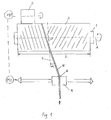
- a winding machine for carrying out the method according to the invention which in Fig. 1 is shown in simplified form, has at least one, but usually a plurality of drivable winding spindles 1 in a pivot bearing.
- a non-illustrated spool core is rotatably attached, is wound onto the strip material 5.
- the strip material 5 is fed at substantially constant linear velocity from a banding device.
- banding devices are known per se and not part of the invention, so that no further explanation is required.
- Each winding spindle 1 or the tape spool 2 which builds up on the spool core is rotated by a contact roller 3, which is rotatable about its own axis and is in circumferential contact with the spool 2 and is driven by a motor M1. Furthermore, a reciprocating over the length of the winding spindle reciprocating device 4 is provided, which has a loop-shaped traversing belt guide 6, through which the tape 5 passes and which the band 5 in a laying angle ⁇ on the coil 2 supplies.
- the laying angle ⁇ is defined as the angle between the supplied belt 5 and a normal S on the coil axis A.
- the winding length L is that axial length in which the winding spindle 1 is wound with the belt 5.
- the Bewicklungsle L corresponds to the coil length and two Bewicklungsdorfn represent the length of a double stroke of the traversing device 4.
- the winder is operated in a stepped precision winding process. This means that, starting from a start laying angle when winding the tape onto a spool core, a certain laying ratio is initially maintained (as a result of which the laying angle changes). When the diameter of the bobbin reaches a predetermined value, the laying ratio is gradually set to a new value, and this in turn is maintained until the bobbin diameter is increased to another predetermined value, whereupon the laying ratio is again set to a new value stepwise.
- the adjustment of the laying ratio is made by an "electronic gear", that is, an electronic control of the ratio of the speeds of the motor 2 driving the coil 2 and a motor M2 reciprocating the traversing device 4.
- the virtual “gear ratio" of the two engines becomes electronic When reaching a certain diameter again and again gradually changed by the traversing M2 is given a changed speed.
- the drives M1, M2 are preferably three-phase drives with frequency converter, or DC drives.
- the instantaneous bobbin diameter is calculated, for example, from a nominal / actual comparison of the thread linear speed and the bobbin rotational speed.
- Fig. 2 shows the graph SPW the step-shaped course in the step precision winding, according to the invention, the laying ratio is changed stepwise by substantially integral steps.
- the change in the laying ratio is only after every 10 mm bobbin diameter increase, from 125 mm bobbin diameter only every 15 mm bobbin diameter increase, and finally from 155 mm bobbin diameter only every 20 mm bobbin diameter increase.
- Table 1 shows the winding ratios of the graph SPW, wherein in column 1 the respective coil diameters are indicated, in which a change in the laying ratio to the values in column 2 takes place.
- Column 3 shows the advance percentage of the laying ratio, which indicates how many complete revolutions the coil performs per double stroke of the traversing device.
- Column 4 shows the fractional part of the laying ratio, from which the offset angle shown in column 6 can be calculated, which indicates by how many degrees the reversal point of the belt is offset after a double stroke of the traversing device with respect to the previous reversal point.
- Column 5 shows the post-decimal difference between successive laying ratios. It can be seen that this difference in the decimal point is in the thousandth range, ie, that the changes in the installation ratio are substantially integer.
- the fractional part of all laying conditions was chosen so that at least two decimal places are provided in each case; in fact, the laying conditions, with the exception of the coil diameter of 125 mm, even have three decimal places.
- the fractional part is close to 0.5 (actually between 0.557 and 0.514), so that after two double strokes of the traversing device the point of reversal of the belt comes to lie again close to the previous reversal point.
- Further preferred value ranges for the fractional part of the laying ratio are close to 0 or 0.33 or 0.25. However, none of these values should themselves be used, since otherwise image windings would occur with each double stroke or after three or four double strokes of the traversing device.
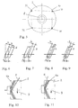
- Fig. 5 schematically shows a coil 2 from the front side, which consists of strip material which is wound on a spool core 8 with a Verlegeparty having a decimal portion of slightly more than 0.25, for example, 0.26. From this an offset angle of just over 90 ° can be calculated.
- the band material is deposited on the bobbin on each double stroke of the traversing device so that the reversal point shifts by approximately 90 ° on the circumference of the coil, resulting in a sequence of reversal points 30 ⁇ 31 ⁇ 32 ⁇ 33 ⁇ 34 results as shown by the dashed arrows. It can be seen that the reversal point 34 is close to the reversal point 30, ie that after four double strokes of the traversing device, the band layers come to lie next to one another.
- FIGS. 6 to 9 When winding tapes on spools, the following configurations of superimposed tape tracks may result in the FIGS. 6 to 9 are shown. These configurations depend on the laying ratio, the laying angle ⁇ , the width b of the tapes 5 and their axial offset d.
- Fig. 6 The bands lie exactly edge to edge.
- Fig. 7 The bands are in between with a gap.
- FIGS. 8 and 9 The band tracks partially overlap, as is preferred according to the invention. This results in Fig. 8 a reverse-running conveyor belt laying and in Fig. 9 a forward belt conveyor.
- the skilled person can determine the required laying ratio V from a desired offset d.
- the offset d In practice, it has proven useful for a construction of a coil with excellent stability, the offset d to be chosen so that an overlap of the ribbon of about a 1 ⁇ 2 ribbon width b sets (see FIGS. 8 and 9 ).
- a negative sign of the offset means "forward" routing.
Landscapes
- Engineering & Computer Science (AREA)
- Textile Engineering (AREA)
- Winding Of Webs (AREA)
- Winding Filamentary Materials (AREA)
- Winding, Rewinding, Material Storage Devices (AREA)
Abstract
Description
Die Erfindung betrifft ein Verfahren zum Aufwickeln eines kontinuierlich zugeführten Bandes auf eine Spule unter Drehung der Spule und Hin- und Herbewegen des Bandes mittels einer Changiereinrichtung über die gesamte Länge der Spule in einem Verlegewinkel, wobei jedesmal, wenn der Spulendurchmesser um einen bestimmmten Wert zugenommen hat, das Verlegeverhältnis, das ist das Verhältnis zwischen Spulendrehzahl und Hin- und Herbewegung (Doppelhub) der Changiereinrichtung, stufenweise geändert wird.The invention relates to a method for winding a continuously fed tape on a spool while rotating the spool and reciprocating the tape by means of a traversing device over the entire length of the spool at a laying angle, each time the spool diameter has increased by a bestimmmten value , the laying ratio, that is the ratio between the reel speed and the reciprocating motion (double stroke) of the traversing device, is changed stepwise.
Ein solches Verfahren zum Aufwickeln eines kontinuierlich zugeführten Bandes wird in Fachkreisen als "gestufte Präzisionswicklung" bezeichnet und ist beispielsweise aus der
Das Aufspulen des Bandes erfolgt in Spulmaschinen auf zylindrische oder konische Spulenkerne, wobei die Zufuhrgeschwindigkeit des Bandes auf den Spulenkern relativ konstant ist, da von der Spulmaschine vorgeschalteten Banderzeugungsmaschinen vorgegeben.The winding of the tape takes place in winding machines on cylindrical or conical coil cores, wherein the feed rate of the tape is relatively constant on the spool core, as given by the winder upstream banding machines.
Das Aussehen, die Festigkeit und Qualität der Spulen wird wesentlich durch die folgenden Parameter beeinflusst:
- 1) Der Verlegewinkel α, das ist jener Winkel zwischen einer Normalen auf die Spulen- Drehachse und der Längsrichtung des auf die Spule zugeführten Bandes.
- 2) Das Verlegeverhältnis V, das ist die Anzahl an Spulenumdrehungen pro Changiereinrichtungs-Doppelhub.
- 1) The laying angle α, which is the angle between a normal to the coil rotation axis and the longitudinal direction of the fed to the coil tape.
- 2) The laying ratio V, which is the number of spool revolutions per reciprocator double stroke.
Aus dem gewählten Verlegeverhältnis V stellt sich der Verlegewinkel α ein.From the chosen laying ratio V, the laying angle α is set.
Eine gestufte Präzisionswicklung ist eine Mischform aus zwei grundlegenden Wickelverfahren, wie das zugeführte Band auf einen Spulenkern gewickelt werden werden kann, nämlich der "Wilden Wicklung" (Zufallswicklung) und der "Präzisionswicklung".A stepped precision winding is a hybrid of two basic winding methods of how the fed tape can be wound on a spool core, namely the "wild winding" and the "precision winding".
Das Kennzeichen der Wilden Wicklung ist ein konstanter Verlegewinkel α, dafür ein variables Verhältnis zwischen Spulendrehzahl und Changiergeschwindigkeit (=variables Verlegeverhältnis V). Im Verlegeverhältnis/Spulendurchmesser-Diagramm von
Die Präzisionswicklung wiederum zeichnet sich durch ein konstantes Verlegeverhältnis über den gesamten anwachsenden Spulendurchmesser aus, was wiederum bedeutet, dass der Verlegewinkel mit zunehmendem Spulendurchmesser abnimmt. Im Diagramm von
Um die jeweiligen Nachteile der Wilden Wicklung und der Präzisionswicklung zu mildern und um ihre Vorteile zu kombinieren, wurde in der Vergangenheit die "gestufte Präzisionswicklung" vorgeschlagen. Diesem Wickelverfahren liegt der Gedanke zugrunde, dass das Verlegeverhältnis zwischen vordefinierten Grenzdurchmessern einer Spule konstant gehalten wird und bei Erreichen eines jeweiligen Grenzdurchmessers stufenweise auf einen anderen Wert verändert wird, wobei die Werte der Verlegeverhältnisse so gewählt werden, dass ein Graph des Verlegeverhältnisses über den Spulendurchmesser ungefähr dem Graph einer Wilden Wicklung für einen bestimmten Verlegewinkel folgt. Der Vorteil der gestuften Präzisionswicklung liegt darin, dass einerseits "Bildwicklungen" vermieden werden, da das sprunghafte Ändern des Verlegeverhältnisses eine "Bildstörungsmaßnahme" darstellt.In order to mitigate the respective disadvantages of the wild winding and the precision winding and to combine their advantages, the "stepped precision winding" has been proposed in the past. This winding method is based on the idea that the laying ratio between predefined limit diameters of a bobbin is kept constant and is gradually changed to a different value when a respective limit diameter is reached, the values of the laying ratios being chosen such that a graph of the laying ratio over the bobbin diameter is approximately follows the graph of a wild winding for a given laying angle. The advantage of stepped precision winding is that, on the one hand, "image windings" are avoided, since the abrupt change in the laying ratio represents a "picture disturbance measure".
Andererseits wird der Verlegewinkel auch bei wachsendem Spulendurchmesser nicht wesentlich kleiner als der Anfangsverlegewinkel.On the other hand, the laying angle is not much smaller than the initial laying angle even with increasing coil diameter.
Während die gestufte Präzisionswicklung für die Herstellung von Garn- und Fadenspulen das erwartete gute Ergebnis liefert, werden bei der Herstellung von Bandspulen mit gestufter Präzisionswicklung oftmals überraschend schlechte Ergebnisse erzielt. Die Unzulänglichkeiten dieser Bandspulen reichen von unansehnlichem, weil unregelmäßigem optischen Erscheinungsbild über Spulen mit variierendem, z.B. welligem Durchmesser über ihre Länge, über unregelmäßige Stirnflächen der Spule, bis hin zu instabilem Wicklungsaufbau.While the stepped precision winding for the production of yarn and bobbins provides the expected good result, surprisingly poor results are often obtained in the production of wound coils with stepped precision winding. The shortcomings of these tape reels range from unsightly because of irregular optical appearance to reels with varying, e.g. Wavy diameter over its length, over irregular end faces of the coil, up to unstable winding structure.
Da solche Spulen meist in schnelllaufenden Maschinen, wie Rundwebstühlen, Verwendung finden, kann jede Unregelmäßigkeit des Spulenaufbaues fatale Folgen haben, die als geringste Auswirkung zum Bruch des Bandes beim Abziehen von der Spule führen, im schlechtesten Fall die Zerstörung eines Teils der Maschine nach sich ziehen. Herbeigeführt werden solche Schäden durch Unwucht an unregelmäßigen Spulen, durch Vibrieren der Bänder beim Abziehen, das sich sukzessive aufschaukelt, etc. Weiters erwärmen sich unregelmäßige Spulen beim schnellen Abziehen der Bänder rasch und führen dadurch zur Ermüdung und Schwächung des Bandmaterials, insbesondere wenn es sich dabei um gereckte Kunststoffbändchen handelt.Since such coils are usually used in high-speed machines, such as rotary looms, any irregularity of the coil structure can have fatal consequences that lead as the least effect to the breakage of the tape when pulling off the coil, in the worst case, the destruction of a part of the machine , Such damage is caused by imbalance on irregular coils, by vibration of the bands during peeling, which gradually aufschaukelt, etc. Furthermore, irregular coils heat quickly when pulling off the tapes and thereby lead to fatigue and weakening of the strip material, especially if it is is about stretched plastic tape.
Aus diesem Grund besteht in der Industrie ein starkes Bedürfnis nach einem verbesserten gestuften Präzisionswickelverfahren.For this reason, there is a strong industry need for an improved stepped precision winding process.
Die vorliegende Erfindung stellt ein solches verbessertes gestuftes Präzisionswickelverfahren bereit, das sich dadurch auszeichnet, dass bei der stufenweisen Änderung des Verlegeverhältnisses dieses um im Wesentlichen ganzzahlige Schritte geändert wird. Die Erfinder haben nämlich erkannt, dass der Grund für einen unzufriedenstellenden Aufbau von Spulen in gestufter Präzisionswicklung die sich durch die stufenweise Änderung des Verlegeverhältnisses ergebende plötzliche Veränderung des Lagenbilds der Bänder ist, die eine Unstetigkeitsstelle für den Gesamtaufbau der Spule darstellt. Im ungünstigen Fall akkumulieren sich diese veränderten Lagenbilder und führen zu den erwähnten Unregelmäßigkeiten oder ungleicher Packungsdichte. Durch die erfindungsgemäße Maßnahme jedoch bleibt auch nach der stufenweisen Änderung des Verlegeverhältnisses das Lagenbild im Wesentlichen unverändert, so dass sich eine Spule mit hervorragendem Aufbau, d.h. regelmäßigem Erscheinungsbild und hoher Packungsdichte ergibt. Stufenweise Änderung des Verlegeverhältnisses um im Wesentlichen ganzzahlige Schritte ist so zu verstehen, dass sich der Nachkommaanteil des Verlegeverhältnisses bei jeder Änderung höchstens um 0,1, bevorzugt höchstens um 0,03, noch bevorzugter um höchstens 0,01 verändert.The present invention provides such an improved stepped precision winding method, which is characterized in that the stepwise change of the laying ratio changes it by substantially integral steps. Namely, the inventors have recognized that the reason for unsatisfactory buildup of coils in stepped precision winding is the sudden change in the layer pattern of the tapes resulting from the stepwise change in the laying ratio, which is a discontinuity for the overall structure of the coil. In the worst case, these altered layer images accumulate and lead to the mentioned irregularities or uneven packing density. By means of the measure according to the invention, however, the layer pattern remains essentially unchanged even after the stepwise change of the laying ratio, so that a coil with an outstanding construction, ie a regular appearance and a high packing density, results. A gradual change in the laying ratio by substantially integral steps should be understood to mean that the fractional part of the laying ratio changes at most by 0.1, preferably at most 0.03, more preferably at most 0.01 at each change.
Gemäß einer bevorzugten Ausgestaltung der Erfindung wird bei einer jeden Änderung des Verlegeverhältnisses der Nachkommaanteil dieses Verhältnisses in dem Ausmaß verändert, dass sich eine konstante Teilüberdeckung mit einer darunter liegenden Bandspur ergibt, wie weiter unten anhand eines Beispiels erläutert wird. Man erzielt dadurch einen sehr stabilen Spulenaufbau.According to a preferred embodiment of the invention, each time the ratio is changed, the fractional part of this ratio is changed to the extent that there is a constant partial coverage with an underlying band track, as will be explained below with reference to an example. This achieves a very stable coil construction.
Bei einem ganzzahligen Verlegeverhältnis, d.h. einem Verlegeverhältnis ohne Kommaanteil stellen sich Bildwicklungen auf der Spule ein. Um solche den Spulenaufbau instabil machenden Bildwicklungen auszuschließen, wird erfindungsgemäß weiters vorgeschlagen, die Verlegeverhältnisse so zu wählen, dass ihr Nachkommaanteil zumindest zweistellig ist. Weiters ist es für Spulen mit Kunststoffbändchen bevorzugt, die Verlegeverhältnisse nahe 0 oder 0,50 oder 0,33 oder 0,25 zu wählen, wodurch die Umkehrpunkte des Bandes an der Stirnseite der Spule nach ein, zwei, drei bzw. vier Doppelhüben des Changierbandführers wieder nahe beieinander zu liegen kommen. In Abhängigkeit von der Breite der aufzuspulenden Bänder kann das Verlegeverhältnis jeweils so geändert werden, dass sich eine vor- oder rückwärtslaufende Bandverlegung ergibt bzw. beibehalten wird.At an integer laying ratio, i. a laying ratio without comma, picture windings set on the coil. In order to exclude image windings which render the coil structure unstable, it is further proposed according to the invention to select the laying conditions such that their fractional part is at least two digits. Furthermore, it is preferred for coils with plastic tapes to choose the laying ratios close to 0 or 0.50 or 0.33 or 0.25, whereby the reversal points of the tape at the end of the coil after one, two, three or four double strokes of the traversing belt guide come close to each other again. Depending on the width of the aufzuspulenden tapes, the laying ratio can each be changed so that results in a forward or backward tape laying or is maintained.
Weiters lassen sich empirisch für jeweilige Breiten der Bänder und ihre Materialeigenschaften bestimmte Verlegewinkelbereiche angeben, die für einen optimalen Aufbau der Spule sorgen. Um diesen optimalen Spulenaufbau zu erreichen, ist vorgesehen, dass das Verlegeverhältnis so geändert wird, dass der resultierende Verlegewinkel innerhalb dieses vorbestimmten Bereichs bleibt. Für gereckte Kunststoffbändchen mit einer Breite zwischen 2 und 10 mm hat sich beispielsweise ein Verlegewinkelbereich von 4 bis 6° als vorteilhaft erwiesen.Furthermore, it is possible empirically to specify specific laying angle ranges for respective widths of the tapes and their material properties, which ensure optimum construction of the coil. In order to achieve this optimum coil construction it is provided that the laying ratio is changed so that the resulting laying angle remains within this predetermined range. For stretched plastic tapes with a width between 2 and 10 mm, for example, a laying angle range of 4 to 6 ° has proven to be advantageous.
Um die erfindungsgemäßen Verlegeverhältnisse mit der erforderlichen Genauigkeit einstellen zu können, hat es sich als günstig erwiesen, wenn die Spule von einem eigenen Motor und die Changiereinrichtung ebenfalls von einem eigenen Motor angetrieben wird und die Änderung des Verlegeverhältnisses elektronisch durch stufenweise Änderung des Verhältnisses der Geschwindigkeiten der beiden Motoren zueinander erfolgt. Besonders gut steuern lassen sich Motoren, die als Drehstromantriebe mit Frequenzumrichter, oder als Gleichstromantriebe aufgebaut sind.In order to adjust the installation conditions according to the invention with the required accuracy, it has proved to be advantageous if the coil is driven by its own engine and the traversing device also by its own motor and the change of the installation ratio electronically by gradually changing the ratio of the speeds of both motors to each other. Particularly well controlled are motors that are constructed as three-phase drives with frequency converter, or as DC drives.
Mit hoher Präzision lässt sich weiters der momentane Spulendurchmesser aus einem Soll/Ist-Vergleich von Bandlineargeschwindigkeit und Spulendrehzahl errechnen.Furthermore, the current coil diameter can be calculated with high precision from a nominal / actual comparison of linear belt speed and coil speed.
Die Erfindung wird nun anhand von Ausführungsbeispielen unter Bezugnahme auf die Zeichnungen näher erläutert. In den Zeichnungen zeigen:
-
Fig. 1 den prinzipiellen Aufbau einer Spulmaschine zur Durchführung des erfindungsgemäßen Verfahrens; -
Fig. 2 ein Diagramm, in dem Graphen des Verlegeverhältnisses über dem Spulendurchmesser für drei Wilde Wicklungen mit Verlegewinkeln α = 4°, α = 5° und α = 6°, für eine Präzisionswicklung V = 35 und für eine gestufte Präzisionswicklung SPW eingetragen sind; -
Fig. 3 die eingangs erklärte Spulmaschine nach dem Stand der Technik zur Erzeugung einer Wilden Wicklung; -
Fig. 4 die eingangs erklärte Spulmaschine nach dem Stand der Technik zur Erzeugung einer Präzisionswicklung; -
Fig. 5 zeigt die Lage von Umkehrpunkten des Bandmaterials an der Stirnseite einer Spule; -
Fig. 6 bis Fig. 9 zeigen verschiedene Konfigurationen übereinanderliegender Bandspuren; und -
Fig. 10 und Fig. 11 zeigen eine vorwärtslaufende bzw. rückwärtslaufende Bandgutverlegung.
-
Fig. 1 the basic structure of a winding machine for carrying out the method according to the invention; -
Fig. 2 a diagram in the graphs of the laying ratio over the coil diameter for three wild windings with laying angles α = 4 °, α = 5 ° and α = 6 °, for a precision winding V = 35 and for a stepped precision winding SPW are entered; -
Fig. 3 the prior art winder according to the prior art for generating a Wild winding; -
Fig. 4 the above-explained winding machine according to the prior art for producing a precision winding; -
Fig. 5 shows the location of reversal points of the strip material on the end face of a coil; -
FIG. 6 to FIG. 9 show different configurations of superimposed tape tracks; and -
10 and FIG. 11 show a forward or reverse running Bandgutverlegung.
Eine Spulmaschine zur Durchführung des erfindungsgemäßen Verfahrens, die in
Die Spulmaschine wird in einem gestuften Präzisionswickelverfahren betrieben. Das heißt, dass ausgehend von einem Start-Verlegewinkel beim Aufspulen des Bandes auf einen Spulenkern zunächst ein bestimmtes Verlegeverhältnis beibehalten wird (wodurch sich der Verlegewinkel ändert). Erreicht der Durchmesser der Spule einen vorbestimmten Wert, so wird das Verlegeverhältnis stufenweise auf einen neuen Wert eingestellt, und dieser wiederum beibehalten, bis der Spulendurchmesser auf einen weiteren vorgegebenen Wert angewachsen ist, woraufhin das Verlegeverhältnis wiederum stufenweise auf einen neuen Wert eingestellt wird.The winder is operated in a stepped precision winding process. This means that, starting from a start laying angle when winding the tape onto a spool core, a certain laying ratio is initially maintained (as a result of which the laying angle changes). When the diameter of the bobbin reaches a predetermined value, the laying ratio is gradually set to a new value, and this in turn is maintained until the bobbin diameter is increased to another predetermined value, whereupon the laying ratio is again set to a new value stepwise.
Die Anpassung des Verlegeverhältnisses erfolgt durch ein "elektronisches Getriebe", d.h. eine elektronische Regelung des Verhältnisses der Geschwindigkeiten des die Spule 2 antreibenden Motors M1 und eines die Changiereinrichtung 4 hin und her bewegenden Motors M2. Das virtuelle "Übersetzungsverhältnis" der beiden Motoren wird elektronisch bei Erreichen eines bestimmten Durchmessers immer wieder stufenweise geändert, indem dem Changierantrieb M2 eine geänderte Geschwindigkeit verliehen wird. Die Antriebe M1, M2 sind vorzugsweise Drehstromantriebe mit Frequenzumrichter, oder Gleichstromantriebe.The adjustment of the laying ratio is made by an "electronic gear", that is, an electronic control of the ratio of the speeds of the
Der momentane Spulendurchmesser wird beispielsweise aus einem Soll/Ist-Vergleich von Fadenlineargeschwindigkeit und Spulendrehzahl errechnet.The instantaneous bobbin diameter is calculated, for example, from a nominal / actual comparison of the thread linear speed and the bobbin rotational speed.
Im Diagramm von
Um "Bildwicklungen" auszuschließen wurde der Nachkommaanteil aller Verlegeverhältnisse so gewählt, dass jeweils mindestens zwei Kommastellen vorgesehen sind; tatsächlich weisen die Verlegeverhältnisse mit Ausnahme im Bereich des Spulendurchmessers von 125 mm sogar drei Kommastellen auf. Der Nachkommaanteil liegt nahe 0,5 (tatsächlich zwischen 0,557 und 0,514), so dass nach zwei Doppelhüben der Changiereinrichtung der Umkehrpunkt des Bandes wieder nahe dem vorherigen Umkehrpunkt zu liegen kommt. Weitere bevorzugte Wertebereiche für den Nachkommaanteil des Verlegeverhältnisses befinden sich nahe 0 oder 0,33 oder 0,25. Allerdings sollte keiner dieser Werte selbst Verwendung finden, da sonst Bildwicklungen bei jedem Doppelhub bzw. nach drei oder vier Doppelhüben der Changiereinrichtung entstehen würden. Zum besseren Verständnis des Zusammenhangs zwischen dem Nachkommaanteil des Verlegeverhältnisses und dem Versatzwinkel ist in
Weiters ist es bevorzugt, das Verlegeverhältnis jeweils so einzustellen, dass sich eine konstante Teilüberdeckung des aufzuwickelnden Bandes mit einer darunter liegenden Bandspur ergibt. Beim Aufwickeln von Bändern auf Spulen können sich die folgenden Konfigurationen übereinanderliegender Bandspuren ergeben, die in den
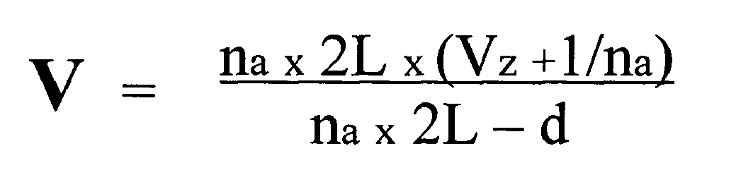
In bevorzugter Ausgestaltung des erfindungsgemäßen Wickelverfahrens wird bei einer jeden Änderung des Verlegeverhältnisses der Nachkommaanteil dieses Verhältnisses in dem Ausmaß verändert, dass sich eine konstante Teilüberdeckung mit einer darunter liegenden Bandspur ergibt. Das Verhältnis zwischen dem axialen Versatz d und dem Verlegeverhältnis V lässt sich aus der nachfolgenden Formel bestimmen: 
wobei gilt:
- V =
- Verlegeverhältnis (z.B. auf vier Kommastellen gerundet)
- Vz =
- Verlegeverhältniszahl (ganzzahlig, gewählter Vorkommaanteil des Verlegeverhältnisses V)
- na =
- Abbindungszahl (ganzzahlig, jene Anzahl Doppelhübe bei der es zu dem definierten Versatz d kommen soll)
- L =
- Bewicklungslänge der Spule in mm (2L → Doppelhub)
- d =
- Versatz in mm (entlang der Wickelachse)
where:
- V =
- Installation ratio (eg rounded to four decimal places)
- Vz =
- Relocation ratio (integer, selected precomport part of the installation ratio V)
- na =
- Abbindungszahl (integer, the number of double strokes at which it should come to the defined offset d)
- L =
- Winding length of the coil in mm (2 L → double stroke)
- d =
- Offset in mm (along the winding axis)
Mit obiger Formel kann der Fachmann aus einem gewünschten Versatz d das dazu notwendige Verlegeverhältnis V bestimmen. In der Praxis hat es sich für einen Aufbau einer Spule mit hervorragender Stabilität bewährt, den Versatz d so zu wählen, dass sich eine Überdeckung der Bändchen von ca. einer ½ Bändchenbreite b einstellt (siehe
Bei einer "vorwärtslaufenden" Bandgutverlegung wird das auf die Spule 2 auflaufende Band 5 vor dem auf der sich in Pfeilrichtung 9 drehenden Spule 2 befindlichen Bandgut 5a abgelegt, wie in
Die obige Formel lässt sich auch so umformulieren, dass in Kenntnis des Verlegeverhältnisses der Versatz d errechnet werden kann: 
Claims (14)
wobei gilt:
where:
Applications Claiming Priority (2)
| Application Number | Priority Date | Filing Date | Title |
|---|---|---|---|
| AT0077003A AT502782B1 (en) | 2003-05-19 | 2003-05-19 | BANDAUFWICKELVERFAHREN |
| EP04731851A EP1625091B2 (en) | 2003-05-19 | 2004-05-10 | Strip winding method |
Related Parent Applications (1)
| Application Number | Title | Priority Date | Filing Date |
|---|---|---|---|
| EP04731851A Division EP1625091B2 (en) | 2003-05-19 | 2004-05-10 | Strip winding method |
Publications (1)
| Publication Number | Publication Date |
|---|---|
| EP1982942A1 true EP1982942A1 (en) | 2008-10-22 |
Family
ID=33437390
Family Applications (2)
| Application Number | Title | Priority Date | Filing Date |
|---|---|---|---|
| EP08013213A Withdrawn EP1982942A1 (en) | 2003-05-19 | 2004-05-10 | Strip coiling method |
| EP04731851A Expired - Lifetime EP1625091B2 (en) | 2003-05-19 | 2004-05-10 | Strip winding method |
Family Applications After (1)
| Application Number | Title | Priority Date | Filing Date |
|---|---|---|---|
| EP04731851A Expired - Lifetime EP1625091B2 (en) | 2003-05-19 | 2004-05-10 | Strip winding method |
Country Status (13)
| Country | Link |
|---|---|
| US (1) | US7762491B2 (en) |
| EP (2) | EP1982942A1 (en) |
| CN (1) | CN100503407C (en) |
| AR (1) | AR044354A1 (en) |
| AT (2) | AT502782B1 (en) |
| BR (1) | BRPI0410774A (en) |
| CL (1) | CL2004001073A1 (en) |
| DE (1) | DE502004008321D1 (en) |
| EG (1) | EG23976A (en) |
| MX (1) | MXPA05012075A (en) |
| RU (1) | RU2309108C2 (en) |
| WO (1) | WO2004101415A1 (en) |
| ZA (1) | ZA200508822B (en) |
Families Citing this family (16)
| Publication number | Priority date | Publication date | Assignee | Title |
|---|---|---|---|---|
| CN101511715B (en) * | 2006-09-06 | 2012-06-06 | 三菱丽阳株式会社 | Carbon fiber package and manufacturing method thereof |
| DE102008008083A1 (en) * | 2008-01-28 | 2009-07-30 | Wilhelm Stahlecker Gmbh | Method and apparatus for making cross-wound packages |
| BR112013014870B8 (en) * | 2010-12-22 | 2021-04-06 | Pirelli | method for controlling the storage of an elementary semi-finished element, and, storage and feeding device for an elementary semi-finished element |
| JP2012250810A (en) * | 2011-06-02 | 2012-12-20 | Murata Machinery Ltd | Thread winder |
| CN102437366B (en) * | 2011-12-09 | 2014-04-16 | 上海步科自动化股份有限公司 | Battery coiling device and coiling control method thereof |
| TWI657992B (en) | 2012-11-12 | 2019-05-01 | 美商南線有限公司 | Wire and cable package |
| CZ20131065A3 (en) * | 2013-12-23 | 2014-06-04 | Technická univerzita v Liberci | Rewind device |
| JP6267580B2 (en) * | 2014-05-14 | 2018-01-24 | Tmtマシナリー株式会社 | Yarn winding device and marking forming method |
| JP6670456B2 (en) * | 2016-09-29 | 2020-03-25 | 日立金属株式会社 | Metal strip coil and method of manufacturing the same |
| DK3597581T3 (en) | 2018-07-17 | 2021-05-17 | Starlinger & Co Gmbh | Tape winding device |
| WO2020075383A1 (en) * | 2018-10-09 | 2020-04-16 | Tmtマシナリー株式会社 | Yarn winding device and yarn winding method |
| JP7361569B2 (en) * | 2019-10-29 | 2023-10-16 | 宇部エクシモ株式会社 | Winding yarn package and its manufacturing method |
| CN111142206A (en) * | 2020-02-26 | 2020-05-12 | 西安西古光通信有限公司 | Optical cable water-blocking tape wrapping device and using method thereof |
| CN112125057B (en) * | 2020-10-15 | 2021-07-16 | 浙江正洪纺织科技股份有限公司 | Intelligent winding device capable of preventing yarn from being loose and adjusting tension |
| CN114715723B (en) * | 2022-02-21 | 2024-12-27 | 浙江精工集成科技股份有限公司 | Wire collection device for carbon fiber winding and forming and carbon fiber winding and forming method |
| CN116135760B (en) * | 2023-04-14 | 2023-06-23 | 广东包庄科技有限公司 | Rolling optimization method and device, electronic equipment and storage medium |
Citations (7)
| Publication number | Priority date | Publication date | Assignee | Title |
|---|---|---|---|---|
| FR2032929A5 (en) * | 1969-03-07 | 1970-11-27 | Sarcem Productions Sa | |
| JPS6194975A (en) * | 1985-09-27 | 1986-05-13 | Tanaka Seiki Kk | Traverse speed controller in winder |
| EP0194524A2 (en) * | 1985-03-05 | 1986-09-17 | B a r m a g AG | Winding method |
| DE3920374A1 (en) * | 1989-06-22 | 1991-01-03 | Schlafhorst & Co W | Cross wound bobbin winding - uses yarn tension and processor to maintain constant winding within bobbin dia. steps |
| DE4112768A1 (en) | 1991-04-19 | 1992-10-22 | Hacoba Textilmaschinen | Computer control for precision winding of cheese packages - using parameters which depend only on bare tube dia. |
| DE4223271C1 (en) | 1992-07-17 | 1993-06-24 | Neumag - Neumuenstersche Maschinen- Und Anlagenbau Gmbh, 2350 Neumuenster, De | |
| EP0561188A1 (en) | 1992-03-16 | 1993-09-22 | Georg Sahm Gmbh & Co. Kg | Procedure for the precision crosswinding of ribbon-like or yarn-like material |
Family Cites Families (12)
| Publication number | Priority date | Publication date | Assignee | Title |
|---|---|---|---|---|
| US3638872A (en) * | 1968-03-28 | 1972-02-01 | Du Pont | Process for winding a yarn package |
| CH603469A5 (en) † | 1975-11-05 | 1978-08-15 | Rieter Ag Maschf | |
| DE3049573A1 (en) * | 1980-12-31 | 1982-07-29 | Fritjof Dipl.-Ing. Dr.-Ing. 6233 Kelkheim Maag | DEVICE FOR PRODUCING YARN BOBBINS |
| US4394986A (en) † | 1981-05-13 | 1983-07-26 | Toray Industries, Inc. | Yarn winding apparatus |
| US4504021A (en) † | 1982-03-20 | 1985-03-12 | Barmag Barmer Maschinenfabrik Ag | Ribbon free wound yarn package and method and apparatus for producing the same |
| US4504024A (en) * | 1982-05-11 | 1985-03-12 | Barmag Barmer Maschinenfabrik Ag | Method and apparatus for producing ribbon free wound yarn package |
| DE3627879C2 (en) * | 1986-08-16 | 1995-09-28 | Barmag Barmer Maschf | Process for winding threads |
| SU1601059A1 (en) * | 1988-05-05 | 1990-10-23 | Ташкентский Институт Текстильной И Легкой Промышленности | Method of winding thread |
| IT1227912B (en) * | 1988-12-23 | 1991-05-14 | Savio Spa | PROCEDURE AND APPARATUS TO DRIVE THE DISTRIBUTION OF THE WIRE ON THE PACKAGE IN FORMATION IN A COLLECTION GROUP FOR SYNTHETIC WIRES |
| DE3918846A1 (en) * | 1989-06-09 | 1990-12-13 | Maag Fritjof | PRAEZISION CROSS COIL, METHOD FOR THE PRODUCTION AND COIL INSTALLATION THEREFOR |
| WO1998033735A1 (en) * | 1997-02-05 | 1998-08-06 | Plant Engineering Consultants, Inc. | Precision winding method and apparatus |
| TW359661B (en) * | 1997-04-24 | 1999-06-01 | Barmag Barmer Maschf | Method of winding a yarn to cylindrical cross-wound package |
-
2003
- 2003-05-19 AT AT0077003A patent/AT502782B1/en not_active IP Right Cessation
-
2004
- 2004-05-10 MX MXPA05012075A patent/MXPA05012075A/en active IP Right Grant
- 2004-05-10 EP EP08013213A patent/EP1982942A1/en not_active Withdrawn
- 2004-05-10 ZA ZA200508822A patent/ZA200508822B/en unknown
- 2004-05-10 WO PCT/AT2004/000162 patent/WO2004101415A1/en not_active Ceased
- 2004-05-10 AT AT04731851T patent/ATE411964T1/en not_active IP Right Cessation
- 2004-05-10 EP EP04731851A patent/EP1625091B2/en not_active Expired - Lifetime
- 2004-05-10 BR BRPI0410774-8A patent/BRPI0410774A/en not_active Application Discontinuation
- 2004-05-10 CN CNB2004800138622A patent/CN100503407C/en not_active Expired - Fee Related
- 2004-05-10 DE DE502004008321T patent/DE502004008321D1/en not_active Expired - Lifetime
- 2004-05-10 US US10/557,752 patent/US7762491B2/en not_active Expired - Fee Related
- 2004-05-10 RU RU2005139552/12A patent/RU2309108C2/en not_active IP Right Cessation
- 2004-05-14 AR ARP040101671A patent/AR044354A1/en active IP Right Grant
- 2004-05-17 CL CL200401073A patent/CL2004001073A1/en unknown
-
2005
- 2005-11-15 EG EGNA2005000729 patent/EG23976A/en active
Patent Citations (7)
| Publication number | Priority date | Publication date | Assignee | Title |
|---|---|---|---|---|
| FR2032929A5 (en) * | 1969-03-07 | 1970-11-27 | Sarcem Productions Sa | |
| EP0194524A2 (en) * | 1985-03-05 | 1986-09-17 | B a r m a g AG | Winding method |
| JPS6194975A (en) * | 1985-09-27 | 1986-05-13 | Tanaka Seiki Kk | Traverse speed controller in winder |
| DE3920374A1 (en) * | 1989-06-22 | 1991-01-03 | Schlafhorst & Co W | Cross wound bobbin winding - uses yarn tension and processor to maintain constant winding within bobbin dia. steps |
| DE4112768A1 (en) | 1991-04-19 | 1992-10-22 | Hacoba Textilmaschinen | Computer control for precision winding of cheese packages - using parameters which depend only on bare tube dia. |
| EP0561188A1 (en) | 1992-03-16 | 1993-09-22 | Georg Sahm Gmbh & Co. Kg | Procedure for the precision crosswinding of ribbon-like or yarn-like material |
| DE4223271C1 (en) | 1992-07-17 | 1993-06-24 | Neumag - Neumuenstersche Maschinen- Und Anlagenbau Gmbh, 2350 Neumuenster, De |
Also Published As
| Publication number | Publication date |
|---|---|
| BRPI0410774A (en) | 2006-06-27 |
| MXPA05012075A (en) | 2006-02-22 |
| RU2309108C2 (en) | 2007-10-27 |
| AT502782B1 (en) | 2008-07-15 |
| CL2004001073A1 (en) | 2005-03-18 |
| AR044354A1 (en) | 2005-09-07 |
| CN100503407C (en) | 2009-06-24 |
| ATE411964T1 (en) | 2008-11-15 |
| ZA200508822B (en) | 2007-07-25 |
| EP1625091B1 (en) | 2008-10-22 |
| HK1092446A1 (en) | 2007-02-09 |
| EG23976A (en) | 2008-02-25 |
| US7762491B2 (en) | 2010-07-27 |
| RU2005139552A (en) | 2006-06-10 |
| DE502004008321D1 (en) | 2008-12-04 |
| CN1802301A (en) | 2006-07-12 |
| EP1625091A1 (en) | 2006-02-15 |
| US20070164145A1 (en) | 2007-07-19 |
| AT502782A1 (en) | 2007-05-15 |
| WO2004101415A1 (en) | 2004-11-25 |
| EP1625091B2 (en) | 2011-09-07 |
Similar Documents
| Publication | Publication Date | Title |
|---|---|---|
| EP1625091B1 (en) | Strip winding method | |
| DE3332382C2 (en) | ||
| DE3242092C2 (en) | ||
| DE68907875T2 (en) | Method for checking the thread guidance on a winder in a winding device for synthetic threads. | |
| DE2649780A1 (en) | WINDING MACHINE FOR TEXTILE YARNS WITH FRICTION ROLLER DRIVE OF THE CROSS REEL | |
| EP0256383B1 (en) | Method to wind up threads | |
| DE3401530A1 (en) | PRECISION COIL, METHOD AND DEVICE FOR PRODUCING THE SAME | |
| EP1600414B1 (en) | Method and apparatus for operating a winding machine producing crosswound bobbins | |
| EP1175364B1 (en) | Method and device for winding a continuously fed thread | |
| EP2595907B1 (en) | Method for producing a textile bobbin and working station for carrying out the method | |
| DE69114151T2 (en) | Apparatus for winding coils from multi-strand cables. | |
| EP0055849A2 (en) | Method and device for winding yarn | |
| WO2007057109A1 (en) | Method for avoiding ribbon windings | |
| EP1151950A2 (en) | Method for operating a textile machine producing crosswound bobbins | |
| EP1514824B1 (en) | Crosswound bobbin and method for producing of such a bobbin | |
| DE112004000172B4 (en) | Garnwickelverfahren and Garnwickelvorrichtung | |
| EP0710616A1 (en) | Procedure and device for winding yarns | |
| EP1481930B1 (en) | Winding machine | |
| DE102008032654A1 (en) | Method and device for disturbing the image when winding a thread | |
| EP1125879A2 (en) | Device for producing a thread reserve and/or an end ridge of thread | |
| DE4024218A1 (en) | Cross wound bobbin winding - uses selected opening and final valves for yarn crossing angle and winding ratio from initial wound layer to last layer | |
| DE2406641A1 (en) | WINDING DEVICE WITH AUTOMATIC REPLACEMENT OF TUBES | |
| EP1222133A2 (en) | Method and device for winding a thread onto a bobbin | |
| EP0401781A1 (en) | Precision wound yarn package, method for its production and device for making same | |
| DE69317108T2 (en) | REWINDING MACHINE FOR MANY THREADS |
Legal Events
| Date | Code | Title | Description |
|---|---|---|---|
| PUAI | Public reference made under article 153(3) epc to a published international application that has entered the european phase |
Free format text: ORIGINAL CODE: 0009012 |
|
| 17P | Request for examination filed |
Effective date: 20080723 |
|
| AC | Divisional application: reference to earlier application |
Ref document number: 1625091 Country of ref document: EP Kind code of ref document: P |
|
| AK | Designated contracting states |
Kind code of ref document: A1 Designated state(s): AT BE BG CH CY CZ DE DK EE ES FI FR GB GR HU IE IT LI LU MC NL PL PT RO SE SI SK TR |
|
| AKX | Designation fees paid |
Designated state(s): AT BE BG CH CY CZ DE DK EE ES FI FR GB GR HU IE IT LI LU MC NL PL PT RO SE SI SK TR |
|
| STAA | Information on the status of an ep patent application or granted ep patent |
Free format text: STATUS: THE APPLICATION IS DEEMED TO BE WITHDRAWN |
|
| 18D | Application deemed to be withdrawn |
Effective date: 20090423 |