EP1982913A1 - Getriebe für fahrrad - Google Patents
Getriebe für fahrrad Download PDFInfo
- Publication number
- EP1982913A1 EP1982913A1 EP07713647A EP07713647A EP1982913A1 EP 1982913 A1 EP1982913 A1 EP 1982913A1 EP 07713647 A EP07713647 A EP 07713647A EP 07713647 A EP07713647 A EP 07713647A EP 1982913 A1 EP1982913 A1 EP 1982913A1
- Authority
- EP
- European Patent Office
- Prior art keywords
- gears
- rotary member
- main
- gear
- switch
- Prior art date
- Legal status (The legal status is an assumption and is not a legal conclusion. Google has not performed a legal analysis and makes no representation as to the accuracy of the status listed.)
- Withdrawn
Links
Images


Classifications
-
- F—MECHANICAL ENGINEERING; LIGHTING; HEATING; WEAPONS; BLASTING
- F16—ENGINEERING ELEMENTS AND UNITS; GENERAL MEASURES FOR PRODUCING AND MAINTAINING EFFECTIVE FUNCTIONING OF MACHINES OR INSTALLATIONS; THERMAL INSULATION IN GENERAL
- F16H—GEARING
- F16H3/00—Toothed gearings for conveying rotary motion with variable gear ratio or for reversing rotary motion
- F16H3/02—Toothed gearings for conveying rotary motion with variable gear ratio or for reversing rotary motion without gears having orbital motion
- F16H3/08—Toothed gearings for conveying rotary motion with variable gear ratio or for reversing rotary motion without gears having orbital motion exclusively or essentially with continuously meshing gears, that can be disengaged from their shafts
- F16H3/083—Toothed gearings for conveying rotary motion with variable gear ratio or for reversing rotary motion without gears having orbital motion exclusively or essentially with continuously meshing gears, that can be disengaged from their shafts with radially acting and axially controlled clutching members, e.g. sliding keys
-
- B—PERFORMING OPERATIONS; TRANSPORTING
- B62—LAND VEHICLES FOR TRAVELLING OTHERWISE THAN ON RAILS
- B62M—RIDER PROPULSION OF WHEELED VEHICLES OR SLEDGES; POWERED PROPULSION OF SLEDGES OR SINGLE-TRACK CYCLES; TRANSMISSIONS SPECIALLY ADAPTED FOR SUCH VEHICLES
- B62M11/00—Transmissions characterised by the use of interengaging toothed wheels or frictionally-engaging wheels
- B62M11/04—Transmissions characterised by the use of interengaging toothed wheels or frictionally-engaging wheels of changeable ratio
- B62M11/14—Transmissions characterised by the use of interengaging toothed wheels or frictionally-engaging wheels of changeable ratio with planetary gears
- B62M11/16—Transmissions characterised by the use of interengaging toothed wheels or frictionally-engaging wheels of changeable ratio with planetary gears built in, or adjacent to, the ground-wheel hub
-
- B—PERFORMING OPERATIONS; TRANSPORTING
- B62—LAND VEHICLES FOR TRAVELLING OTHERWISE THAN ON RAILS
- B62M—RIDER PROPULSION OF WHEELED VEHICLES OR SLEDGES; POWERED PROPULSION OF SLEDGES OR SINGLE-TRACK CYCLES; TRANSMISSIONS SPECIALLY ADAPTED FOR SUCH VEHICLES
- B62M11/00—Transmissions characterised by the use of interengaging toothed wheels or frictionally-engaging wheels
- B62M11/04—Transmissions characterised by the use of interengaging toothed wheels or frictionally-engaging wheels of changeable ratio
- B62M11/14—Transmissions characterised by the use of interengaging toothed wheels or frictionally-engaging wheels of changeable ratio with planetary gears
- B62M11/145—Transmissions characterised by the use of interengaging toothed wheels or frictionally-engaging wheels of changeable ratio with planetary gears built in, or adjacent to, the bottom bracket
-
- B—PERFORMING OPERATIONS; TRANSPORTING
- B62—LAND VEHICLES FOR TRAVELLING OTHERWISE THAN ON RAILS
- B62M—RIDER PROPULSION OF WHEELED VEHICLES OR SLEDGES; POWERED PROPULSION OF SLEDGES OR SINGLE-TRACK CYCLES; TRANSMISSIONS SPECIALLY ADAPTED FOR SUCH VEHICLES
- B62M11/00—Transmissions characterised by the use of interengaging toothed wheels or frictionally-engaging wheels
- B62M11/04—Transmissions characterised by the use of interengaging toothed wheels or frictionally-engaging wheels of changeable ratio
- B62M11/14—Transmissions characterised by the use of interengaging toothed wheels or frictionally-engaging wheels of changeable ratio with planetary gears
- B62M11/18—Transmissions characterised by the use of interengaging toothed wheels or frictionally-engaging wheels of changeable ratio with planetary gears with a plurality of planetary gear units
-
- F—MECHANICAL ENGINEERING; LIGHTING; HEATING; WEAPONS; BLASTING
- F16—ENGINEERING ELEMENTS AND UNITS; GENERAL MEASURES FOR PRODUCING AND MAINTAINING EFFECTIVE FUNCTIONING OF MACHINES OR INSTALLATIONS; THERMAL INSULATION IN GENERAL
- F16H—GEARING
- F16H3/00—Toothed gearings for conveying rotary motion with variable gear ratio or for reversing rotary motion
- F16H3/02—Toothed gearings for conveying rotary motion with variable gear ratio or for reversing rotary motion without gears having orbital motion
- F16H3/08—Toothed gearings for conveying rotary motion with variable gear ratio or for reversing rotary motion without gears having orbital motion exclusively or essentially with continuously meshing gears, that can be disengaged from their shafts
-
- F—MECHANICAL ENGINEERING; LIGHTING; HEATING; WEAPONS; BLASTING
- F16—ENGINEERING ELEMENTS AND UNITS; GENERAL MEASURES FOR PRODUCING AND MAINTAINING EFFECTIVE FUNCTIONING OF MACHINES OR INSTALLATIONS; THERMAL INSULATION IN GENERAL
- F16H—GEARING
- F16H9/00—Gearings for conveying rotary motion with variable gear ratio, or for reversing rotary motion, by endless flexible members
- F16H9/02—Gearings for conveying rotary motion with variable gear ratio, or for reversing rotary motion, by endless flexible members without members having orbital motion
- F16H9/24—Gearings for conveying rotary motion with variable gear ratio, or for reversing rotary motion, by endless flexible members without members having orbital motion using chains or toothed belts, belts in the form of links; Chains or belts specially adapted to such gearing
Definitions
- This invention relates to a covered bicycle transmission for transmitting driving force at different reduction ratios by changing gears.
- Patent document 1 discloses such a covered bicycle transmission, which includes gear case mounted in a frame, a driven rotary member rotatable relative to a crankshaft which rotates under the pedal force, a sprocket fixed to one side thereof, a carrier rotationally fixed to the crankshaft, a plurality of steps of planetary gears mounted on shafts fixed to the carrier, and rotatable sun gears provided inside of and meshing with the respective steps of planetary gears.
- One step of the planetary gears mesh with an internal gear of the driven rotary member which is provided radially outwardly of the one step of the planetary gears.
- a ratchet mechanism is provided between the carrier and the driven rotary member to absorb the rotational speed difference therebetween.
- Patent document 2 discloses a transmission including a gear case fixed to a frame, and a driven rotary member rotatable relative to a crankshaft which is rotated under the pedal force.
- a sprocket and a large-diameter sun gear are integrally formed on one and the other side of the driven rotary member.
- Large-diameter planetary gears and small-diameter planetary gears are supported on shafts fixed to a carrier which is rotationally fixed relative to the crankshaft.
- a small-diameter sun gear rotatable relative to the crankshaft is provided radially inwardly of and meshes with the large-diameter planetary gears.
- the large-diameter sun gear is located radially inwardly of and meshes with the small-diameter planetary gears.
- Internal gears are provided radially outwardly of and mesh with the large-diameter and small-diameter planetary gears, respectively.
- a ratchet mechanism is provided between the small-diameter sun gear and the driven rotary member to absorb the rotational speed difference therebetween.
- An object of the present invention is to provide a covered bicycle transmission which is simple in structure and can be mounted on various types of existing bicycles.
- the present invention provides a bicycle transmission comprising a rotary member fitted around a main shaft, as many main gears as the number of reduction steps which are arranged in a row around the rotary member, a plurality of counter gears rotationally fixed to a countershaft extending parallel to the main shaft, the counter gears being linked to the respective main gears and rotated at predetermined speeds corresponding to the respective main gears, ratchet pawls carried on the rotary member so as to correspond to the respective main gears, the main gears having ratchet teeth on their inner peripheries with which the respective ratchet pawls are configured to be brought into meshing engagement, and a switch member for selectively protruding and retracting the respective ratchet pawls from and into an outer periphery of the rotary member, wherein by operating the switch member, the ratchet pawls are individually and selectively brought into and out of engagement with the corresponding ratchet teeth, whereby driving force is selective
- the switch member is provided radially inwardly of the rotary member and has a plurality of recesses formed in the outer periphery thereof so as to be circumferentially displaced from each other, wherein when the switch member is rotated relative to the rotary member, the ratchet pawls slide along the outer periphery of the switch member and selectively and individually protrude from and retract into the rotary member.
- the bicycle transmission may further comprise a nonrotatable stationary member, and an operating member that rotates by pulling and pushing an operating wire.
- differential gears are mounted on shafts provided on the stationary member and the operating member, respectively, the differential gears meshing with external teeth formed on the switch member and the rotary member, respectively, and meshing with internal teeth formed on a ring member provided therearound, whereby the rotational speed ratio is changed by the relative rotation between the switch member and the rotary member.
- the main shaft may be a crankshaft that rotates under the pedal force.
- the transmission is configured to transmit the rotation of the crankshaft as an input member to a front sprocket as an output member.
- the main shaft may be an axle supporting a bicycle rear wheel.
- the transmission is configured to transmit the rotation of a rear sprocket as an input member to an outer case as an output member.
- the bicycle transmission according to this invention As many main gears as the number of reduction steps are associated with the corresponding counter gears at predetermined speed ratios.
- the switch member By operating the switch member, the ratchet pawls are selectively brought into and out of engagement with the corresponding ratchet teeth, thereby switching the main gear through which driving force is transmitted to the corresponding counter gear.
- the bicycle transmission according to the invention is simple in structure, can be manufactured at a low cost, and is reliable in use.
- the bicycle transmission according to this invention is compact in size, and can be easily mounted on existing bicycles using general-purpose parts. Even if this transmission has many steps, it is possible to change the speed ratio smoothly and comfortably.
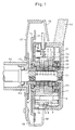
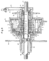
- Figs. 1 to 4 is a 4-step covered transmission mounted on the crankshaft of a bicycle.
- this transmission is fitted on the crankshaft 51 and fixed in position by fitting a boss of a crankcase 53 integral with a crank arm 52.
- the crankshaft 51 is supported by a crank boss 54 of the bicycle frame through a bearing 55 and is rotated under the stepping force applied to pedals at the free ends of the crank arms 52.
- a rotary member 1 is in threaded engagement with the outer periphery of the crankshaft 51 so as to be rotationally fixed to the crankshaft 51.
- four main gears i.e. fourth-speed gear 2, third-speed gear 3, first-speed gear 4 and second-speed gear 5 are arranged from right to left in Fig. 1 so as to be rotatable relative to each other.
- each countershaft carries four counter gears 7 to 9.
- the counter gears 7 to 9 have their bosses secured to each countershaft 6 so that each counter gear is rotated at a predetermined speed ratio by the corresponding one of the main gears 2 to 5 by meshing with it.
- the main gears 2 to 5 and the counter gears 7 to 10 are received in a cylindrical gear case 11.
- the countershafts 6 have their ends supported by the gear case 11.
- the gear case 11 comprises right and left halves that are joined together by clamp bolts 12, and is rotationally fixed to a support plate 57 of a chain case 56 by means of an anti-rotation member 58.
- the main gear 5 is rotatably supported by the rotary member 1 through a bearing 13.
- a sprocket 14 is mounted on the left-hand portion of the main gear 5, which protrudes from the gear case 11.
- a chain 59 for driving the rear bicycle wheel is trained around the sprocket 14.
- the gear case 11 has a sufficiently small outer diameter so as to be received in the sprocket 14.
- the rotary member 1 carries ratchet pawls 15 to 18 that correspond to the respective main gears 2 to 5.
- Each ratchet pawl is biased such that its distal end protrudes radially outwardly and engages one of ratchet teeth 19 formed on the inner periphery of each of the main gears 2 to 5.
- a cylindrical switch member 20 is inserted in the rotary member 1 so as to be rotatable relative to the crankshaft 51 and the rotary member 1.
- the switch member 20 has in its outer periphery a plurality of groups of recesses 21 (which are actually through holes) such that each group of through holes radially oppose one of the main gears 2 to 5 and circumferentially displaced from the other groups of through holes.
- the ratchet pawls 15 to 18 have their proximal ends in sliding contact with the outer periphery of the switch member 20.
- an operating member 22 having external teeth on the outer periphery thereof within its 120° range is rotatably mounted around the rotary member 1.
- a switch gear 24 is rotationally fixedly mounted on a switch shaft 23 rotatably supported by the gear case 11 so as to mesh with the external teeth of the operating member 22.
- the core of a wire 25 extending from an operating lever mounted on the handlebar of the bicycle and a coil spring 26 are wound around and coupled to the switch shaft 23.
- the switch gear 24 is rotated in one direction.
- the switch gear 24 is rotated in the other direction under the biasing force of the coil spring 26.
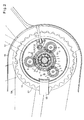
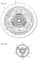
- differential gears 27 are rotatably supported on shafts fixed to the operating member 22 and circumferentially spaced from each other at intervals of 90°.
- the differential gears 27 mesh with external teeth formed on the rotary member 1 and internal teeth formed on a ring member 28 provided therearound.
- the differential gears 27 carried on the operating member 22 and the differential gears 27 carried on the gear case 11 are kept out of contact with each other by a ring-shaped partition plate 29 disposed therebetween.
- the proximal ends of the ratchet pawls 15 are engaged in the corresponding recesses 21 of the switch member 20, so that their distal ends engage the internal teeth 19 of the main gear 2.
- the other ratchet pawls 16, 17 and 18 are kept out of engagement with the internal teeth 19 of the respective main gears 3, 4 and 5.
- the rotation of the crankshaft 51 as the input member is transmitted through the rotary member 1 to the main gear 2, which has the largest diameter.
- the counter gear 7 is rotated at the speed corresponding to the peripheral speed of the main gear 2.
- the rotation of the counter gear 7 is then transmitted through the counter gear 10, which is rotationally fixed to the gear 7, and the main gear 5 to the sprocket 14 as the output member.
- the bicycle rear wheel is rotated at the highest speed.
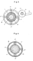
- the rotation of the rotary member 1 is transmitted to the ring member 28 through the differential gears 27 of the operating member 22, and from the ring member 28 to the switch member 20 through the differential gears 27 of the gear case 11.
- the switch member 20 rotates in unison with the rotary member 1.
- the operating member 22 rotates by one step together with the switch gear 24, so that its shafts supporting the respective differential gears 27 move circumferentially around the crankshaft 51.
- This causes the ring member 28 to rotate relative to the rotary member 1, which in turn causes the switch member 20 to rotate relative to the rotary member 1.
- the proximal ends of the ratchet pawls 16 are engaged in the corresponding recesses 21 of the switch member 20, so that their distal ends engage the internal teeth 19 of the main gear 3.
- the ratchet pawls 15 retract into the rotary member 1.
- the ratchet pawls 15, 17 and 18 are kept out of engagement with the internal teeth 19 of the respective main gears 2, 4 and 5.
- the rotation of the crankshaft 51 is transmitted through the rotary member 1 to the main gear 3, which has a diameter one size smaller than the main gear 2.
- the counter gear 8 is rotated at the speed corresponding to the peripheral speed of the main gear 3.
- the rotation of the counter gear 8 is then transmitted through the counter gear 10, which is rotationally fixed to the gear 8, and the main gear 5 to the sprocket 14.
- the bicycle rear wheel is rotated at the one-step lower speed.
- the operating member 22 rotates by two steps, so that the switch member 20 rotates relative to the rotary member 1 in the same manner as described above, until the ratchet pawls 18 protrude from the rotary member 1 and engage the internal teeth 19 of the main gear 5.
- the ratchet pawls 15, 16 and 17 are kept out of engagement with the internal teeth 19 of the respective main gears 2, 3 and 4, so that the bicycle rear wheel is rotated at the two-step lower speed through the sprocket 14, which is rotationally fixed to the main gear 5.
- the operating member 22 rotates by three steps, so that the switch member 20 rotates relative to the rotary member 1 in the same manner as described above, until the ratchet pawls 17 protrude from the rotary member 1 and engage the internal teeth 19 of the main gear 4, which has the smallest diameter.
- the ratchet pawls 15, 16 and 18 are kept out of engagement with the internal teeth 19 of the respective main gears 2, 3 and 5.
- the rotation of the main gear 4 is transmitted through the counter gear 10, which is rotationally fixed to the counter gear 9, and the main gear 5 to the sprocket 14.
- the bicycle rear wheel is rotated at the three-step lower speed (i.e. lowest speed).
- the speed reduction ratio is determined by the numbers of the teeth of gears on two shafts, even if this transmission is a four-speed or more than four-speed transmission, it is more compact in size than planetary gear type transmissions, and still, it can be smoothly upshifted and downshifted according to various travel conditions without giving uncomfortable feeling to the rider.
- This transmission can be mounted on an existing bicycle with no transmission. Because the switch mechanism of this transmission has a short axial length, with this transmission mounted on an existing bicycle, the crank arm coupled to the transmission never protrudes outwardly to such an extent as to make pedaling difficult. Also, since the weight of the transmission acts on the central portion of the bicycle, the rider can lift and move the bicycle in a balanced manner.
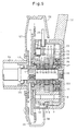
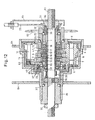
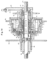
- Figs. 8 to 14 show the second embodiment of the present invention, which is a 4-step covered transmission mounted on the rear wheel of a bicycle. Elements functionally similar or identical to those of the first embodiment are denoted by identical numerals, and their description is omitted.
- the axle 61 of the rear wheel serves as a main shaft of the transmission, and the rotation is transmitted from a rear sprocket 62 as an input member to an outer case 63 as an output member.
- Two flanges 64 are mounted around the outer case 63 so as to be spaced apart from each other.
- Each flange 64 is formed with engaging holes at circumferentially equal intervals in which spokes of the rear wheel are engaged.
- This transmission includes a support nut 30 threaded onto the axle 61 from its right-hand end, an intermediate support ring 31 fitted on the support nut 30, a switch ring 32 rotatably fitted around the intermediate support ring 31, and a bearing seat 33 also fitted on the intermediate support ring 31.
- a core of a wire 25 supported by a support member 65 is wound around and coupled to the switch ring 32. By operating the transmission through the wire 25, the switch ring 32 is rotated in either direction.
- a rotary member 1 is mounted around the axle 61 with a play. At its right-hand end, the rotary member 1 is rotatably supported on the axle through a bearing 35 between a bearing seat 34 threaded onto the right-hand end of the rotary member 1 and the bearing seat 33.
- the outer case 63 is rotationally fixed to the main gear 5 thorough a lid member.
- the outer case 63 is rotatably supported on a bearing seat 36 fitted on the axle 61 through a bearing 37.
- the bearing seat 36 and the gear case 11 are fixed to the axle 61 by means of nuts 38 and 39 threaded onto the axle 61 from its left-hand end.
- the operating member 22 includes a tubular portion rotatably inserted between the axle 61 and the switch member 20 and having its right-hand end in engagement with the switch ring 32.
- the switch ring 32 is thus rotationally fixed to the operating member 22.
- the coil spring 26 biasing the operating member 22 in the upshifting direction is coupled to the left-hand end of the operating member 22 and the nut 38.
- the operating member 22 has a disk portion carrying three shafts circumferentially spaced from each other at intervals of 120° and each rotatably supporting a differential gear 27.
- the differential gears 27 mesh with external teeth formed on the switch member 20 and internal teeth formed on a ring member 28 provided therearound.
- the operating member 22 rotates by one step together with the switch ring 32, so that its shafts supporting the respective differential gears 27 move circumferentially around the axle 61.
- This causes the ring member 28 to rotate relative to the rotary member 1, which in turn causes the switch member 20 to rotate relative to the rotary member 1.
- the proximal ends of the ratchet pawls 16 are engaged in the corresponding recesses 21 of the switch member 20, so that their distal ends engage the internal teeth 19 of the main gear 3.
- the ratchet pawls 15 retract into the rotary member 1.
- the ratchet pawls 15, 17 and 18 are kept out of engagement with the internal teeth 19 of the respective main gears 2, 4 and 5.
- the rotation of the sprocket 62 is transmitted through the rotary member 1 to the main gear 3, which has a diameter one size smaller than the main gear 2.
- the counter gear 8 is rotated at the speed corresponding to the peripheral speed of the main gear 3.
- the rotation of the counter gear 8 is then transmitted through the counter gear 10, which is rotationally fixed to the gear 8, and the main gear 5 to the outer case 63.
- the bicycle rear wheel is rotated at the one-step lower speed.
- the operating member 22 rotates by two steps, so that the switch member 20 rotates relative to the rotary member 1 in the same manner as described above, until the ratchet pawls 18 protrude from the rotary member 1 and engage the internal teeth 19 of the main gear 5.
- the ratchet pawls 15, 16 and 17 are kept out of engagement with the internal teeth 19 of the respective main gears 2, 3 and 4, so that the bicycle rear wheel is rotated at the two-step lower speed through the outer case 63, which is rotationally fixed to the main gear 5.
- the operating member 22 rotates by three steps, so that the switch member 20 rotates relative to the rotary member 1 in the same manner as described above, until the ratchet pawls 17 protrude from the rotary member 1 and engage the internal teeth 19 of the main gear 4, which has the smallest diameter.
- the ratchet pawls 15, 16 and 18 are kept out of engagement with the internal teeth 19 of the respective main gears 2, 3 and 5.
- the rotation of the main gear 4 is transmitted through the counter gear 10, which is rotationally fixed to the counter gear 9, and the main gear 5 to the outer case 63.
- the bicycle rear wheel is rotated at the three-step lower speed (i.e. lowest speed).
- the operating member 22 When upshifted in this state, the operating member 22 is rotated in the opposite direction under the biasing force of the coil spring 26, thereby rotating the switch member 20 in the direction opposite to the downshifting direction, thus selectively protruding and retracting the respective ratchet pawls 15 to 18 from and into the rotary member 1.
- this transmission is a four-speed or more than four-speed transmission, its circumferential and axial dimensions are substantially the same as those of existing 3-step covered transmissions.
- this transmission when this transmission is mounted on any newly manufactured bicycle, it is not necessary to change the design of the mounting portion of the rear wheel, so that it is possible to use general-purpose parts for such a mounting portion, thereby reducing the cost. Still, it can be smoothly upshifted and downshifted according to various travel conditions without giving uncomfortable feeling to the rider.
Landscapes
- Engineering & Computer Science (AREA)
- Mechanical Engineering (AREA)
- General Engineering & Computer Science (AREA)
- Chemical & Material Sciences (AREA)
- Combustion & Propulsion (AREA)
- Transportation (AREA)
- Structure Of Transmissions (AREA)
- Transmissions By Endless Flexible Members (AREA)
Applications Claiming Priority (2)
| Application Number | Priority Date | Filing Date | Title |
|---|---|---|---|
| JP2006034117A JP4134183B2 (ja) | 2006-02-10 | 2006-02-10 | 自転車用変速装置 |
| PCT/JP2007/050760 WO2007091414A1 (ja) | 2006-02-10 | 2007-01-19 | 自転車用変速装置 |
Publications (2)
| Publication Number | Publication Date |
|---|---|
| EP1982913A1 true EP1982913A1 (de) | 2008-10-22 |
| EP1982913A4 EP1982913A4 (de) | 2010-11-17 |
Family
ID=38345021
Family Applications (1)
| Application Number | Title | Priority Date | Filing Date |
|---|---|---|---|
| EP07713647A Withdrawn EP1982913A4 (de) | 2006-02-10 | 2007-01-19 | Getriebe für fahrrad |
Country Status (6)
| Country | Link |
|---|---|
| US (1) | US20090062057A1 (de) |
| EP (1) | EP1982913A4 (de) |
| JP (1) | JP4134183B2 (de) |
| KR (1) | KR20080101927A (de) |
| CN (1) | CN101384473A (de) |
| WO (1) | WO2007091414A1 (de) |
Cited By (14)
| Publication number | Priority date | Publication date | Assignee | Title |
|---|---|---|---|---|
| DE102008064514A1 (de) * | 2008-12-22 | 2010-07-01 | Fineschnitt Gmbh | Getriebeeinheit |
| DE102009060484A1 (de) | 2009-12-18 | 2011-06-22 | FINESCHNITT GmbH, 70469 | Schaltvorrichtung und Getriebeeinheit |
| CN110537038A (zh) * | 2017-05-19 | 2019-12-03 | By金株式会社 | 马达的多档变速器 |
| EP3456620A4 (de) * | 2016-05-12 | 2020-01-08 | Bok Soung Kim | Nabe für eine fahrradgangschaltung |
| EP3704013A1 (de) * | 2017-11-02 | 2020-09-09 | Wilfried Donner | Antriebsstrang mit zwei separaten, mittels zwischengetriebe gekoppelten schaltbaren getrieben |
| DE102022107155A1 (de) | 2022-03-25 | 2023-09-28 | Karlheinz Nicolai | Prozessor und Verfahren, insbesondere computer-implementiertes Verfahren, zur Steuerung eines Nabenschaltgetriebes eines Fahrrads mit Hilfsmotor sowie Nabenschaltung mit einem solchen Prozessor |
| WO2023180299A1 (de) | 2022-03-25 | 2023-09-28 | Karlheinz Nicolai | Prozessor und verfahren, insbesondere computer-implementiertes verfahren, zur steuerung eines tretlagerschaltgetriebes eines fahrrads mit hilfsmotor sowie tretlagerschaltung mit einem solchen prozessor |
| DE102022001734A1 (de) | 2022-05-17 | 2023-11-23 | Karlheinz Nicolai | Tretlagerschaltung mit Hilfsantrieb für ein Fahrrad und ein Fahrrad mit einer solchen Tretlagerschaltung |
| DE102022001737A1 (de) | 2022-05-17 | 2023-11-23 | Karlheinz Nicolai | Tretlagerschaltung mit Sensoranordnung für ein Elektrofahrrad und Elektrofahrrad mit einer solchen Tretlagerschaltung |
| WO2023222261A1 (de) | 2022-05-17 | 2023-11-23 | Karlheinz Nicolai | Tretlagerschaltung mit hochfesten zahnrädern für ein fahrrad und ein fahrrad mit einer solchen tretlagerschaltung |
| WO2023222259A1 (de) | 2022-05-17 | 2023-11-23 | Karlheinz Nicolai | Tretlagerschaltung mit betätigungsvorrichtung für ein fahrrad und ein fahrrad mit einer solchen tretlagerschaltung |
| DE102022001739A1 (de) | 2022-05-17 | 2023-11-23 | Karlheinz Nicolai | Tretlagerschaltung mit Schaltvorrichtung für ein Fahrrad und ein Fahrrad mit einer solchen Tretlagerschaltung |
| DE102023207638B3 (de) | 2023-08-09 | 2024-10-02 | Karlheinz Nicolai | Tretlagerschaltung für ein Fahrrad sowie Fahrrad mit einem Antriebsstrang mit einer solchen Tretlagerschaltung |
| DE102023121281A1 (de) | 2023-08-09 | 2025-02-13 | Karlheinz Nicolai | Getriebeeinheit mit Schaltvorrichtung für ein Fahrrad |
Families Citing this family (13)
| Publication number | Priority date | Publication date | Assignee | Title |
|---|---|---|---|---|
| US8342553B2 (en) * | 2009-05-27 | 2013-01-01 | Patterson Bicycle Transmission Llc | Mounting method for bottom bracket planetary |
| JP5188474B2 (ja) * | 2009-08-19 | 2013-04-24 | 喬紳股▲ふん▼有限公司 | 常閉式無音ハブラチェット構造 |
| US8414006B2 (en) | 2010-07-27 | 2013-04-09 | Nanh Souvanny | Bicycle device with direct drive transmission and hubless wheels |
| DE102010049438A1 (de) * | 2010-10-23 | 2012-04-26 | Sram Deutschland Gmbh | Betätigungsmechanik für eine Mehrfach-Fahrradgetriebenabe |
| US9033833B2 (en) | 2011-01-28 | 2015-05-19 | Paha Designs, Llc | Gear transmission and derailleur system |
| US9327792B2 (en) | 2011-01-28 | 2016-05-03 | Paha Designs, Llc | Gear transmission and derailleur system |
| US10207772B2 (en) | 2011-01-28 | 2019-02-19 | Paha Designs, Llc | Gear transmission and derailleur system |
| DE102011106107B4 (de) * | 2011-06-09 | 2023-10-05 | Pinion Gmbh | Schaltvorrichtung, Getriebeeinheit und Verfahren zum Schalten einer Getriebeeinheit |
| TW201514057A (zh) * | 2013-10-14 | 2015-04-16 | Chen zheng he | 二輪載具結構(二) |
| ITMI20132176A1 (it) * | 2013-12-20 | 2015-06-21 | Stefano Mangini | Cambio a più rapporti per velocipede ad assetto variabile |
| US9725132B2 (en) * | 2014-03-26 | 2017-08-08 | Shimano Inc. | Bicycle crank assembly |
| NO341940B1 (en) * | 2016-03-01 | 2018-02-26 | Ca Tech Systems As | Sequential gear shifter |
| US10300986B2 (en) * | 2016-04-27 | 2019-05-28 | Shimano Inc. | Bicycle transmission apparatus and bicycle drive unit |
Family Cites Families (13)
| Publication number | Priority date | Publication date | Assignee | Title |
|---|---|---|---|---|
| GB449285A (en) * | 1935-10-01 | 1936-06-24 | Albert Hofer | Change speed gear for cycles |
| JPS5370047U (de) * | 1976-11-14 | 1978-06-12 | ||
| US4376394A (en) * | 1978-12-13 | 1983-03-15 | Lapeyre Fernand S | Manually operable multi-speed bicycle transmission |
| JPS6299293A (ja) * | 1985-10-25 | 1987-05-08 | ブリヂストンサイクル株式会社 | 自転車用変速装置 |
| US4702121A (en) * | 1986-07-10 | 1987-10-27 | Hartmann Dirck T | Multiple speed driving wheel for pedal powered vehicles |
| JP2599596B2 (ja) * | 1987-07-13 | 1997-04-09 | 株式会社シマノ | 自転車用変速装置 |
| GB8922042D0 (en) * | 1989-09-29 | 1989-11-15 | Harding Stephen M | A variable speed drive mechanism |
| JPH06263081A (ja) * | 1993-03-12 | 1994-09-20 | Bridgestone Cycle Co | 自転車用変速装置 |
| JP3423756B2 (ja) * | 1993-12-16 | 2003-07-07 | 株式会社シマノ | 自転車用動作装置の操作構造 |
| US5553510A (en) * | 1995-02-27 | 1996-09-10 | Balhorn; Alan C. | Multi-speed transmission |
| DE19720796B4 (de) * | 1997-05-16 | 2005-10-20 | Bernhard Rohloff | Mehrgang-Getriebenabe für Fahrräder |
| JP3065927U (ja) * | 1999-07-21 | 2000-02-08 | 財団法人工業技術研究院 | 多段変速リム変速制御機構 |
| JP2006306360A (ja) * | 2005-03-31 | 2006-11-09 | Fujiwara Wheel:Kk | 自転車用変速装置 |
-
2006
- 2006-02-10 JP JP2006034117A patent/JP4134183B2/ja not_active Expired - Fee Related
-
2007
- 2007-01-19 WO PCT/JP2007/050760 patent/WO2007091414A1/ja not_active Ceased
- 2007-01-19 US US12/223,694 patent/US20090062057A1/en not_active Abandoned
- 2007-01-19 EP EP07713647A patent/EP1982913A4/de not_active Withdrawn
- 2007-01-19 KR KR1020087020422A patent/KR20080101927A/ko not_active Withdrawn
- 2007-01-19 CN CNA2007800051533A patent/CN101384473A/zh active Pending
Cited By (30)
| Publication number | Priority date | Publication date | Assignee | Title |
|---|---|---|---|---|
| DE102008064514A1 (de) * | 2008-12-22 | 2010-07-01 | Fineschnitt Gmbh | Getriebeeinheit |
| DE102009060484A1 (de) | 2009-12-18 | 2011-06-22 | FINESCHNITT GmbH, 70469 | Schaltvorrichtung und Getriebeeinheit |
| WO2011073360A1 (de) | 2009-12-18 | 2011-06-23 | Pinion Gmbh | Schaltvorrichtung und getriebeeinheit |
| DE102009060484B4 (de) * | 2009-12-18 | 2020-04-16 | Pinion Gmbh | Mit Muskelkraft antreibbares Fahrzeug |
| EP3456620A4 (de) * | 2016-05-12 | 2020-01-08 | Bok Soung Kim | Nabe für eine fahrradgangschaltung |
| CN110537038A (zh) * | 2017-05-19 | 2019-12-03 | By金株式会社 | 马达的多档变速器 |
| EP3597963A4 (de) * | 2017-05-19 | 2021-01-13 | Bok Soung Kim | Mehrganggetriebe für motor |
| US11287015B2 (en) | 2017-05-19 | 2022-03-29 | Bok Soung KIM | Multi-speed transmission for motor |
| TWI766018B (zh) * | 2017-05-19 | 2022-06-01 | 金福成 | 用於馬達的多重速度傳動裝置 |
| CN110537038B (zh) * | 2017-05-19 | 2023-01-20 | By金株式会社 | 马达的多挡变速器 |
| EP3704013A1 (de) * | 2017-11-02 | 2020-09-09 | Wilfried Donner | Antriebsstrang mit zwei separaten, mittels zwischengetriebe gekoppelten schaltbaren getrieben |
| EP3704013B1 (de) * | 2017-11-02 | 2025-08-06 | Wilfried Donner | Antriebsstrang mit zwei separaten, mittels zwischengetriebe gekoppelten schaltbaren getrieben |
| DE102022107161A1 (de) | 2022-03-25 | 2023-09-28 | Karlheinz Nicolai | Prozessor und Verfahren, insbesondere computer-implementiertes Verfahren, zur Steuerung eines Tretlagerschaltgetriebes eines Fahrrads mit Hilfsmotor sowie Tretlagerschaltung mit einem solchen Prozessor |
| WO2023180299A1 (de) | 2022-03-25 | 2023-09-28 | Karlheinz Nicolai | Prozessor und verfahren, insbesondere computer-implementiertes verfahren, zur steuerung eines tretlagerschaltgetriebes eines fahrrads mit hilfsmotor sowie tretlagerschaltung mit einem solchen prozessor |
| WO2023180538A1 (de) | 2022-03-25 | 2023-09-28 | Karlheinz Nicolai | Prozessor und verfahren, insbesondere computer-implementiertes verfahren, zur steuerung eines nabenschaltgetriebes eines fahrrads mit hilfsmotor sowie getriebeschaltsystem mit einem solchen prozessor |
| DE102022107155A1 (de) | 2022-03-25 | 2023-09-28 | Karlheinz Nicolai | Prozessor und Verfahren, insbesondere computer-implementiertes Verfahren, zur Steuerung eines Nabenschaltgetriebes eines Fahrrads mit Hilfsmotor sowie Nabenschaltung mit einem solchen Prozessor |
| DE102022001738A1 (de) | 2022-05-17 | 2023-11-23 | Karlheinz Nicolai | Tretlagerschaltung mit Betätigungsvorrichtung für ein Fahrrad und ein Fahrrad mit einer solchen Tretlagerschaltung |
| WO2023222260A1 (de) | 2022-05-17 | 2023-11-23 | Karlheinz Nicolai | Tretlagerschaltung mit schaltvorrichtung für ein fahrrad und ein fahrrad mit einer solchen tretlagerschaltung |
| WO2023222262A1 (de) | 2022-05-17 | 2023-11-23 | Karlheinz Nicolai | Tretlagerschaltung mit sensoranordnung für ein elektrofahrrad und elektrofahrrad mit einer solchen tretlagerschaltung |
| WO2023222259A1 (de) | 2022-05-17 | 2023-11-23 | Karlheinz Nicolai | Tretlagerschaltung mit betätigungsvorrichtung für ein fahrrad und ein fahrrad mit einer solchen tretlagerschaltung |
| DE102022001739A1 (de) | 2022-05-17 | 2023-11-23 | Karlheinz Nicolai | Tretlagerschaltung mit Schaltvorrichtung für ein Fahrrad und ein Fahrrad mit einer solchen Tretlagerschaltung |
| DE102022001737A1 (de) | 2022-05-17 | 2023-11-23 | Karlheinz Nicolai | Tretlagerschaltung mit Sensoranordnung für ein Elektrofahrrad und Elektrofahrrad mit einer solchen Tretlagerschaltung |
| WO2023222263A1 (de) | 2022-05-17 | 2023-11-23 | Karlheinz Nicolai | Tretlagerschaltung mit hilfsantrieb für ein fahrrad und ein fahrrad mit einer solchen tretlagerschaltung |
| WO2023222261A1 (de) | 2022-05-17 | 2023-11-23 | Karlheinz Nicolai | Tretlagerschaltung mit hochfesten zahnrädern für ein fahrrad und ein fahrrad mit einer solchen tretlagerschaltung |
| DE102022001740A1 (de) | 2022-05-17 | 2023-11-23 | Karlheinz Nicolai | Tretlagerschaltung mit hochfesten Zahnrädern für ein Fahrrad und ein Fahrrad mit einer solchen Tretlagerschaltung |
| DE102022001734A1 (de) | 2022-05-17 | 2023-11-23 | Karlheinz Nicolai | Tretlagerschaltung mit Hilfsantrieb für ein Fahrrad und ein Fahrrad mit einer solchen Tretlagerschaltung |
| DE102023121281A1 (de) | 2023-08-09 | 2025-02-13 | Karlheinz Nicolai | Getriebeeinheit mit Schaltvorrichtung für ein Fahrrad |
| WO2025031767A1 (de) | 2023-08-09 | 2025-02-13 | Karlheinz Nicolai | Tretlagerschaltung für ein fahrrad |
| EP4512709A1 (de) | 2023-08-09 | 2025-02-26 | Karlheinz Nicolai | Getriebeeinheit mit schaltvorrichtung für ein fahrrad |
| DE102023207638B3 (de) | 2023-08-09 | 2024-10-02 | Karlheinz Nicolai | Tretlagerschaltung für ein Fahrrad sowie Fahrrad mit einem Antriebsstrang mit einer solchen Tretlagerschaltung |
Also Published As
| Publication number | Publication date |
|---|---|
| EP1982913A4 (de) | 2010-11-17 |
| JP4134183B2 (ja) | 2008-08-13 |
| WO2007091414A1 (ja) | 2007-08-16 |
| US20090062057A1 (en) | 2009-03-05 |
| CN101384473A (zh) | 2009-03-11 |
| KR20080101927A (ko) | 2008-11-21 |
| JP2007210520A (ja) | 2007-08-23 |
Similar Documents
| Publication | Publication Date | Title |
|---|---|---|
| EP1982913A1 (de) | Getriebe für fahrrad | |
| CN102770338B (zh) | 换挡装置和传动单元 | |
| RU2527579C2 (ru) | Устройство планетарной коробки передач велосипеда | |
| JP4726932B2 (ja) | 自転車用内装変速ハブ | |
| US7644944B2 (en) | Multiple gear transmission for a bicycle | |
| EP2683602B1 (de) | Mehrganggetriebesystem | |
| US5399128A (en) | Multi-speed drive hub with a separate mounting ring for the planetary gearset for bicycles | |
| US20110130242A1 (en) | Multi-Speed Internal Gear Hub for a Bicycle | |
| EP2586694A1 (de) | Fahrrad mit elektrischem hilfsmotor | |
| JP4852071B2 (ja) | 自転車用内装変速ハブ | |
| US12128987B2 (en) | Drive train comprising two separate shiftable gear mechanisms which are coupled by means of intermediate gear mechanisms | |
| JPH06263080A (ja) | 自転車用変速装置 | |
| CN106627975B (zh) | 一种直线踩踏单轮直驱变速器 | |
| KR200246082Y1 (ko) | 중차축의쌍방향변속기 | |
| CN106741562B (zh) | 一种直线踩踏单轮直驱齿圈中心轮固定变速器 | |
| EP1112922A2 (de) | Fahrradantriebsnabe | |
| CN110843996A (zh) | 适用于自行车的变速箱 | |
| JPH07205874A (ja) | 自転車用変速装置 | |
| JP2005306267A (ja) | 自転車用変速装置 | |
| JPH06239285A (ja) | 自転車用変速装置 | |
| JPH06234388A (ja) | 自転車用変速装置 | |
| JPH06179388A (ja) | 自転車用変速装置 | |
| CN120773865A (zh) | 用于人力车辆或轻型电动车辆的变速器系统 | |
| TW202533987A (zh) | 人力驅動車用變速器及人力驅動車用組件 | |
| CN120936541A (zh) | 自行车变速器 |
Legal Events
| Date | Code | Title | Description |
|---|---|---|---|
| PUAI | Public reference made under article 153(3) epc to a published international application that has entered the european phase |
Free format text: ORIGINAL CODE: 0009012 |
|
| 17P | Request for examination filed |
Effective date: 20080806 |
|
| AK | Designated contracting states |
Kind code of ref document: A1 Designated state(s): DE FR GB IT |
|
| DAX | Request for extension of the european patent (deleted) | ||
| RBV | Designated contracting states (corrected) |
Designated state(s): DE FR GB IT |
|
| A4 | Supplementary search report drawn up and despatched |
Effective date: 20101014 |
|
| STAA | Information on the status of an ep patent application or granted ep patent |
Free format text: STATUS: THE APPLICATION IS DEEMED TO BE WITHDRAWN |
|
| 18D | Application deemed to be withdrawn |
Effective date: 20110513 |