EP1980673A2 - Laderanbaugerät mit mindestens zwei parallelen Armen - Google Patents
Laderanbaugerät mit mindestens zwei parallelen Armen Download PDFInfo
- Publication number
- EP1980673A2 EP1980673A2 EP08004964A EP08004964A EP1980673A2 EP 1980673 A2 EP1980673 A2 EP 1980673A2 EP 08004964 A EP08004964 A EP 08004964A EP 08004964 A EP08004964 A EP 08004964A EP 1980673 A2 EP1980673 A2 EP 1980673A2
- Authority
- EP
- European Patent Office
- Prior art keywords
- transverse strut
- attachment
- arms
- attachment according
- strut
- Prior art date
- Legal status (The legal status is an assumption and is not a legal conclusion. Google has not performed a legal analysis and makes no representation as to the accuracy of the status listed.)
- Granted
Links
Images




Classifications
-
- E—FIXED CONSTRUCTIONS
- E02—HYDRAULIC ENGINEERING; FOUNDATIONS; SOIL SHIFTING
- E02F—DREDGING; SOIL-SHIFTING
- E02F3/00—Dredgers; Soil-shifting machines
- E02F3/04—Dredgers; Soil-shifting machines mechanically-driven
- E02F3/28—Dredgers; Soil-shifting machines mechanically-driven with digging tools mounted on a dipper- or bucket-arm, i.e. there is either one arm or a pair of arms, e.g. dippers, buckets
- E02F3/36—Component parts
- E02F3/42—Drives for dippers, buckets, dipper-arms or bucket-arms
- E02F3/43—Control of dipper or bucket position; Control of sequence of drive operations
-
- E—FIXED CONSTRUCTIONS
- E02—HYDRAULIC ENGINEERING; FOUNDATIONS; SOIL SHIFTING
- E02F—DREDGING; SOIL-SHIFTING
- E02F3/00—Dredgers; Soil-shifting machines
- E02F3/04—Dredgers; Soil-shifting machines mechanically-driven
- E02F3/28—Dredgers; Soil-shifting machines mechanically-driven with digging tools mounted on a dipper- or bucket-arm, i.e. there is either one arm or a pair of arms, e.g. dippers, buckets
- E02F3/34—Dredgers; Soil-shifting machines mechanically-driven with digging tools mounted on a dipper- or bucket-arm, i.e. there is either one arm or a pair of arms, e.g. dippers, buckets with bucket-arms, i.e. a pair of arms, e.g. manufacturing processes, form, geometry, material of bucket-arms directly pivoted on the frames of tractors or self-propelled machines
-
- E—FIXED CONSTRUCTIONS
- E02—HYDRAULIC ENGINEERING; FOUNDATIONS; SOIL SHIFTING
- E02F—DREDGING; SOIL-SHIFTING
- E02F3/00—Dredgers; Soil-shifting machines
- E02F3/04—Dredgers; Soil-shifting machines mechanically-driven
- E02F3/64—Buckets cars, i.e. having scraper bowls
- E02F3/65—Component parts, e.g. drives, control devices
- E02F3/651—Hydraulic or pneumatic drives; Electric or electro-mechanical control devices
-
- E—FIXED CONSTRUCTIONS
- E02—HYDRAULIC ENGINEERING; FOUNDATIONS; SOIL SHIFTING
- E02F—DREDGING; SOIL-SHIFTING
- E02F3/00—Dredgers; Soil-shifting machines
- E02F3/04—Dredgers; Soil-shifting machines mechanically-driven
- E02F3/76—Graders, bulldozers, or the like with scraper plates or ploughshare-like elements; Levelling scarifying devices
- E02F3/80—Component parts
- E02F3/84—Drives or control devices therefor, e.g. hydraulic drive systems
-
- E—FIXED CONSTRUCTIONS
- E02—HYDRAULIC ENGINEERING; FOUNDATIONS; SOIL SHIFTING
- E02F—DREDGING; SOIL-SHIFTING
- E02F9/00—Component parts of dredgers or soil-shifting machines, not restricted to one of the kinds covered by groups E02F3/00 - E02F7/00
- E02F9/20—Drives; Control devices
- E02F9/22—Hydraulic or pneumatic drives
-
- E—FIXED CONSTRUCTIONS
- E02—HYDRAULIC ENGINEERING; FOUNDATIONS; SOIL SHIFTING
- E02F—DREDGING; SOIL-SHIFTING
- E02F9/00—Component parts of dredgers or soil-shifting machines, not restricted to one of the kinds covered by groups E02F3/00 - E02F7/00
- E02F9/20—Drives; Control devices
- E02F9/22—Hydraulic or pneumatic drives
- E02F9/2264—Arrangements or adaptations of elements for hydraulic drives
- E02F9/2267—Valves or distributors
Definitions
- the invention relates to a loader attachment for a working vehicle such as a tractor having at least two arms extending in parallel and at least one transverse strut for connecting the said arms and having feeds for electrical and/or fluid-carrying supply lines in at least one of the said arms.
- a loader attachment for a working vehicle having at least two arms, produced in the form of hollow bodies, which extend substantially in parallel, and at least one transverse hollow strut, for connecting the said arms, at least one of the said hollow arms, containing fluid-carrying lines and/or electrical lines characterised in that the transverse strut and/or the arms form an interconnected installation space in which is mounted at least one component for controlling the attachment or implements fastened thereto.
- control components may be mounted inside the cross-section of the transverse strut and the transition which the supply lines make from the arms to the transverse strut is effected inside the arm.
- a loader attachment 1 which is connected, by its end 2 which is at the rear in the direction of travel C, to a working vehicle (not shown) such as an agricultural or construction tractor and whose front end has mounted an implement such as an attachment frame 3 for a bucket for bulk material.
- the attachment 1 comprises, in essence, two arms 4, which are produced in the form of substantially enclosed, welded frame-like structures in the embodiment, which structures are connected together in the front region by a transverse strut 6. Because the embodiment is symmetrical in construction on the two sides, it will be only the part of the embodiment which is situated on the right, looking in the direction of travel, that will be described in what follows.
- the bottom region of the arm 4 comprises an arm bottom portion 5 of enclosed construction having an inner side-wall 5a, an outer side-wall 5b, an upper wall 5c and a lower wall 5d.
- the enclosed cross-section of the arm 4 and the arm bottom portion 5 are mounted hydraulic inlet lines 7 to the control components 8 for controlling the attachment I or implements fastened to the attachment frame 3. These inlet lines extend from the portion 2 of the arm 4 which is at the rear in the direction of travel to the transverse strut 6.
- the transverse strut 6 is produced in the form of an enclosed, welded hexagonal profile whose edges are radiused in the embodiment and which comprises a front side-wall 6a, a rear side-wall 6b, a radiused-edged lower wall 6c in the bottom region of the profile and a radiused-edged upper wall 6d in the top region of the profile.
- the transverse strut 6 has open ends.
- the arm bottom portion 5 is provided with a perforation 5e through the side-walls 5a, 5b which extends perpendicularly to the side-walls 5a, 5b.
- the perforation 5e is of the same shape as the external outline of the transverse strut 6 and is spaced away from the external outline of the transverse strut 6, in parallel thereto, at a distance of 0.5 to 1 mm, thus enabling the perforation 5e to receive the transverse strut 6.
- the transverse strut 6 is passed through the perforation 5e so that the open end 6e of the transverse strut 6 projects beyond the outer side-wall 5b of the arm bottom portion 5, and it is non-releasably connected to the arm bottom portion 5, by means of the two side-walls 5a, 5b, by a surrounding weld.
- the two parts are non-releasably connected to a stiffener 9.
- the transverse strut is provided with a perforation 6f which extends through the rear side-wall 6b and parts of the upper and lower walls 6c, 6d and through which the inlet lines 7 are run into the cross-section 6g of the transverse strut 6.
- a carrier member 10 on which all the control components 8 (e.g. solenoid operated fluid flow control valves) for controlling the attachment 1 or implements fastened to the attachment frame 3 are mounted.
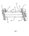
- the carrier member 10 is provided on both sides with a fold 10b whose plane is parallel to the lower wall 6c of the transverse strut 6, which folds 10b rest, in the fitted state, on the inside faces of the bottom wall 6d of the transverse strut 6 to provide centering and positioning.
- the folds are each provided with three holes 10c and welded captive nuts 10d by which, as shown in Fig. 5 , the carrier member 10 is releasably connected to the transverse strut 6 by six fastening screws 11.
- the control components 8 and the connecting block 12 for the outlet lines 13 are screwed to the carrier member 10 by means of the supports 10a.
- intermediate connections 14 which, via clamps 15, are connected to the supports 10a on the carrier member 10 by screwed connections and whose positions are thus fixed.
- Standard commercial ring-nut connections are provided for connecting the inlet lines 7, outlet lines 13, intermediate connections 14 and control components 8 to one another.
- the open lateral ends 6e of the transverse strut 6 are provided with a cover 16 which stops dirt from entering the installation space 6h in the transverse strut 6 and thus stops the control components from becoming fouled or being damaged.
- the cover 16 is provided with spacers (not shown) which create a surrounding air gap between the cover 16 and the outer side-wall 5b through which temperature is equalised with the ambient air and any overheating of the components situated within the cross-section is thus counter-acted.
- spacers not shown
- FIG. 7 shows the connection of the outlet lines 13 to the connecting block 12.
- the view in section in Fig. 7 shows the connection of the outlet lines 13 to the connecting block 12.
- the outlet lines 13 are connected to these screw-in fittings 18, once again by ring-nut connections.
- the carrier member 10 is now moved out of the transverse strut 6 in direction F, whereby all the components which are mounted on the carrier member 10, such as the control components 8, the connecting block 12 and the intermediate connections 14, are freely accessible for maintenance tasks or replacement.
- electrical lines for operating valves 8 or other component may also extend inside arms 4 and transverse strut 6 alongside fluid lines 7. These electrical lines may also enter or leave strut 6 through the walls of strut 6 alongside fluid lines 13.
Landscapes
- Engineering & Computer Science (AREA)
- Mining & Mineral Resources (AREA)
- Civil Engineering (AREA)
- General Engineering & Computer Science (AREA)
- Structural Engineering (AREA)
- Mechanical Engineering (AREA)
- Lifting Devices For Agricultural Implements (AREA)
- Agricultural Machines (AREA)
Priority Applications (1)
| Application Number | Priority Date | Filing Date | Title |
|---|---|---|---|
| PL08004964T PL1980673T3 (pl) | 2007-04-10 | 2008-03-17 | Mocowanie ładowarki mające co najmniej dwa równoległe ramiona |
Applications Claiming Priority (1)
| Application Number | Priority Date | Filing Date | Title |
|---|---|---|---|
| GB0706797A GB2448312B (en) | 2007-04-10 | 2007-04-10 | Loader attachment having at least two parallel arms |
Publications (3)
| Publication Number | Publication Date |
|---|---|
| EP1980673A2 true EP1980673A2 (de) | 2008-10-15 |
| EP1980673A3 EP1980673A3 (de) | 2017-05-10 |
| EP1980673B1 EP1980673B1 (de) | 2018-08-01 |
Family
ID=38091023
Family Applications (1)
| Application Number | Title | Priority Date | Filing Date |
|---|---|---|---|
| EP08004964.6A Active EP1980673B1 (de) | 2007-04-10 | 2008-03-17 | Laderanbaugerät mit mindestens zwei parallelen Armen |
Country Status (3)
| Country | Link |
|---|---|
| EP (1) | EP1980673B1 (de) |
| GB (1) | GB2448312B (de) |
| PL (1) | PL1980673T3 (de) |
Cited By (1)
| Publication number | Priority date | Publication date | Assignee | Title |
|---|---|---|---|---|
| CN104114774A (zh) * | 2012-02-15 | 2014-10-22 | 日立建机株式会社 | 双臂式作业机械 |
Citations (1)
| Publication number | Priority date | Publication date | Assignee | Title |
|---|---|---|---|---|
| WO2006036014A1 (ja) | 2004-09-30 | 2006-04-06 | Nishihara Environment Technology, Inc. | 凝集分離装置 |
Family Cites Families (7)
| Publication number | Priority date | Publication date | Assignee | Title |
|---|---|---|---|---|
| US3539021A (en) * | 1968-05-20 | 1970-11-10 | Caterpillar Tractor Co | Arrangement of flexible conduits for track-type tractors |
| US4050596A (en) * | 1975-07-24 | 1977-09-27 | Control Concepts, Inc. | Electrohydraulic valve assembly for front end loader attachment to farm tractor |
| JP3309337B2 (ja) * | 1997-10-06 | 2002-07-29 | 新キャタピラー三菱株式会社 | アーム機構内配管取付構造及び取付方法 |
| US6655899B1 (en) * | 1998-03-16 | 2003-12-02 | Earl William Emerson | Multi-purpose front loader attachment |
| GB2399836B (en) * | 2003-03-27 | 2005-09-28 | Bamford Excavators Ltd | Earthmoving blade and mounting assembly |
| SE531215C2 (sv) * | 2004-09-29 | 2009-01-20 | Aaloe Ab | Lastare innefattande två armdelar försett med ett utrymme i vilket slangar/ledningar är dragna |
| JP4217687B2 (ja) * | 2005-03-14 | 2009-02-04 | ヤンマー株式会社 | ローダの配管構造 |
-
2007
- 2007-04-10 GB GB0706797A patent/GB2448312B/en not_active Expired - Fee Related
-
2008
- 2008-03-17 EP EP08004964.6A patent/EP1980673B1/de active Active
- 2008-03-17 PL PL08004964T patent/PL1980673T3/pl unknown
Patent Citations (1)
| Publication number | Priority date | Publication date | Assignee | Title |
|---|---|---|---|---|
| WO2006036014A1 (ja) | 2004-09-30 | 2006-04-06 | Nishihara Environment Technology, Inc. | 凝集分離装置 |
Cited By (3)
| Publication number | Priority date | Publication date | Assignee | Title |
|---|---|---|---|---|
| CN104114774A (zh) * | 2012-02-15 | 2014-10-22 | 日立建机株式会社 | 双臂式作业机械 |
| CN104114774B (zh) * | 2012-02-15 | 2016-09-07 | 日立建机株式会社 | 双臂式作业机械 |
| US9458602B2 (en) | 2012-02-15 | 2016-10-04 | Hitachi Construction Machinery Co., Ltd. | Dual-arm work machine |
Also Published As
| Publication number | Publication date |
|---|---|
| GB2448312A (en) | 2008-10-15 |
| EP1980673B1 (de) | 2018-08-01 |
| PL1980673T3 (pl) | 2019-01-31 |
| EP1980673A3 (de) | 2017-05-10 |
| GB0706797D0 (en) | 2007-05-16 |
| GB2448312B (en) | 2010-11-10 |
Similar Documents
| Publication | Publication Date | Title |
|---|---|---|
| US20160082831A1 (en) | Industrial vehicle | |
| CN104816626B (zh) | 作业车 | |
| US20110002765A1 (en) | Excavator boom | |
| EP2423077B1 (de) | Fahrgestell | |
| EP1799919B1 (de) | Ladevorrichtung mit armabschnitten, die einen raum aufweisen, der sich entlang dem arm erstreckt und in dem rohre oder kabel angeordnet sind | |
| EP1980673B1 (de) | Laderanbaugerät mit mindestens zwei parallelen Armen | |
| EP3029207B1 (de) | Baumaschine | |
| DE60102417T2 (de) | Strahlplatte mit hoher Effizienz für Temperaturregulierung eines Raumes | |
| EP3779209A1 (de) | Auf einem fahrgestell aufgebautes hydraulikaggregat zum betrieb einer auf einer festen bodenoberfläche selbstfahrenden arbeitsmaschine | |
| DE112015005101T5 (de) | Anordnungskonstruktion für einen Reduktionsmitteltank einer Baumaschine | |
| EP2821272A1 (de) | Nutzfahrzeug | |
| RU2655587C1 (ru) | Ось моста в сборе | |
| BRPI1102739B1 (pt) | armação de sustentação para fixação lateral de peças complementares em um suporte longitudinal de uma estrutura de sustentação de veículo utilitário | |
| US12090812B2 (en) | Construction machine | |
| JP5993830B2 (ja) | 建設機械 | |
| BR102015020183A2 (pt) | permutador de calor, tanque para permutador de calor, e modo de fazer o mesmo | |
| US20150345369A1 (en) | Shunt tank for engine cooling systems | |
| AU2021200717B2 (en) | Power cable routing for a motor case | |
| JP2006007982A (ja) | 車両の前部構造 | |
| US20250109568A1 (en) | Front loader | |
| EP2135798A1 (de) | Flüssigkeitsbehälter | |
| DE112019004394T5 (de) | Anordnung zum Fördern der Entfernung von verdampftem Flüssiggas eines Flüssiggastreibstoffsystems eines Fahrzeuges | |
| BR102016003261A2 (pt) | conjunto de válvulas justapostas, e, máquina de trabalho | |
| US11724557B2 (en) | Assembly for a hydraulically suspended vehicle axle | |
| EP3360760B1 (de) | Fahrzeugchassisbaugruppe |
Legal Events
| Date | Code | Title | Description |
|---|---|---|---|
| PUAI | Public reference made under article 153(3) epc to a published international application that has entered the european phase |
Free format text: ORIGINAL CODE: 0009012 |
|
| AK | Designated contracting states |
Kind code of ref document: A2 Designated state(s): AT BE BG CH CY CZ DE DK EE ES FI FR GB GR HR HU IE IS IT LI LT LU LV MC MT NL NO PL PT RO SE SI SK TR |
|
| AX | Request for extension of the european patent |
Extension state: AL BA MK RS |
|
| PUAL | Search report despatched |
Free format text: ORIGINAL CODE: 0009013 |
|
| AK | Designated contracting states |
Kind code of ref document: A3 Designated state(s): AT BE BG CH CY CZ DE DK EE ES FI FR GB GR HR HU IE IS IT LI LT LU LV MC MT NL NO PL PT RO SE SI SK TR |
|
| AX | Request for extension of the european patent |
Extension state: AL BA MK RS |
|
| RIC1 | Information provided on ipc code assigned before grant |
Ipc: E02F 9/14 20060101ALI20170401BHEP Ipc: E02F 3/38 20060101AFI20170401BHEP Ipc: E02F 9/22 20060101ALI20170401BHEP Ipc: E02F 3/34 20060101ALI20170401BHEP |
|
| STAA | Information on the status of an ep patent application or granted ep patent |
Free format text: STATUS: REQUEST FOR EXAMINATION WAS MADE |
|
| 17P | Request for examination filed |
Effective date: 20171110 |
|
| RBV | Designated contracting states (corrected) |
Designated state(s): AT BE BG CH CY CZ DE DK EE ES FI FR GB GR HR HU IE IS IT LI LT LU LV MC MT NL NO PL PT RO SE SI SK TR |
|
| AKX | Designation fees paid |
Designated state(s): AT BE BG CH CY CZ DE DK EE ES FI FR GB GR HR HU IE IS IT LI LT LU LV MC MT NL NO PL PT RO SE SI SK TR |
|
| AXX | Extension fees paid |
Extension state: BA Extension state: MK Extension state: AL Extension state: RS |
|
| GRAP | Despatch of communication of intention to grant a patent |
Free format text: ORIGINAL CODE: EPIDOSNIGR1 |
|
| STAA | Information on the status of an ep patent application or granted ep patent |
Free format text: STATUS: GRANT OF PATENT IS INTENDED |
|
| RIC1 | Information provided on ipc code assigned before grant |
Ipc: E02F 3/34 20060101ALI20180302BHEP Ipc: E02F 9/14 20060101ALI20180302BHEP Ipc: E02F 3/38 20060101AFI20180302BHEP Ipc: E02F 9/22 20060101ALI20180302BHEP |
|
| INTG | Intention to grant announced |
Effective date: 20180328 |
|
| GRAS | Grant fee paid |
Free format text: ORIGINAL CODE: EPIDOSNIGR3 |
|
| GRAA | (expected) grant |
Free format text: ORIGINAL CODE: 0009210 |
|
| STAA | Information on the status of an ep patent application or granted ep patent |
Free format text: STATUS: THE PATENT HAS BEEN GRANTED |
|
| AK | Designated contracting states |
Kind code of ref document: B1 Designated state(s): AT BE BG CH CY CZ DE DK EE ES FI FR GB GR HR HU IE IS IT LI LT LU LV MC MT NL NO PL PT RO SE SI SK TR |
|
| REG | Reference to a national code |
Ref country code: GB Ref legal event code: FG4D |
|
| REG | Reference to a national code |
Ref country code: CH Ref legal event code: EP Ref country code: AT Ref legal event code: REF Ref document number: 1024465 Country of ref document: AT Kind code of ref document: T Effective date: 20180815 |
|
| REG | Reference to a national code |
Ref country code: IE Ref legal event code: FG4D |
|
| REG | Reference to a national code |
Ref country code: DE Ref legal event code: R096 Ref document number: 602008056205 Country of ref document: DE |
|
| REG | Reference to a national code |
Ref country code: NL Ref legal event code: MP Effective date: 20180801 |
|
| REG | Reference to a national code |
Ref country code: LT Ref legal event code: MG4D |
|
| REG | Reference to a national code |
Ref country code: AT Ref legal event code: MK05 Ref document number: 1024465 Country of ref document: AT Kind code of ref document: T Effective date: 20180801 |
|
| PG25 | Lapsed in a contracting state [announced via postgrant information from national office to epo] |
Ref country code: AT Free format text: LAPSE BECAUSE OF FAILURE TO SUBMIT A TRANSLATION OF THE DESCRIPTION OR TO PAY THE FEE WITHIN THE PRESCRIBED TIME-LIMIT Effective date: 20180801 Ref country code: BG Free format text: LAPSE BECAUSE OF FAILURE TO SUBMIT A TRANSLATION OF THE DESCRIPTION OR TO PAY THE FEE WITHIN THE PRESCRIBED TIME-LIMIT Effective date: 20181101 Ref country code: SE Free format text: LAPSE BECAUSE OF FAILURE TO SUBMIT A TRANSLATION OF THE DESCRIPTION OR TO PAY THE FEE WITHIN THE PRESCRIBED TIME-LIMIT Effective date: 20180801 Ref country code: GR Free format text: LAPSE BECAUSE OF FAILURE TO SUBMIT A TRANSLATION OF THE DESCRIPTION OR TO PAY THE FEE WITHIN THE PRESCRIBED TIME-LIMIT Effective date: 20181102 Ref country code: LT Free format text: LAPSE BECAUSE OF FAILURE TO SUBMIT A TRANSLATION OF THE DESCRIPTION OR TO PAY THE FEE WITHIN THE PRESCRIBED TIME-LIMIT Effective date: 20180801 Ref country code: NL Free format text: LAPSE BECAUSE OF FAILURE TO SUBMIT A TRANSLATION OF THE DESCRIPTION OR TO PAY THE FEE WITHIN THE PRESCRIBED TIME-LIMIT Effective date: 20180801 Ref country code: FI Free format text: LAPSE BECAUSE OF FAILURE TO SUBMIT A TRANSLATION OF THE DESCRIPTION OR TO PAY THE FEE WITHIN THE PRESCRIBED TIME-LIMIT Effective date: 20180801 Ref country code: NO Free format text: LAPSE BECAUSE OF FAILURE TO SUBMIT A TRANSLATION OF THE DESCRIPTION OR TO PAY THE FEE WITHIN THE PRESCRIBED TIME-LIMIT Effective date: 20181101 Ref country code: IS Free format text: LAPSE BECAUSE OF FAILURE TO SUBMIT A TRANSLATION OF THE DESCRIPTION OR TO PAY THE FEE WITHIN THE PRESCRIBED TIME-LIMIT Effective date: 20181201 |
|
| PG25 | Lapsed in a contracting state [announced via postgrant information from national office to epo] |
Ref country code: LV Free format text: LAPSE BECAUSE OF FAILURE TO SUBMIT A TRANSLATION OF THE DESCRIPTION OR TO PAY THE FEE WITHIN THE PRESCRIBED TIME-LIMIT Effective date: 20180801 Ref country code: HR Free format text: LAPSE BECAUSE OF FAILURE TO SUBMIT A TRANSLATION OF THE DESCRIPTION OR TO PAY THE FEE WITHIN THE PRESCRIBED TIME-LIMIT Effective date: 20180801 Ref country code: ES Free format text: LAPSE BECAUSE OF FAILURE TO SUBMIT A TRANSLATION OF THE DESCRIPTION OR TO PAY THE FEE WITHIN THE PRESCRIBED TIME-LIMIT Effective date: 20180801 |
|
| PG25 | Lapsed in a contracting state [announced via postgrant information from national office to epo] |
Ref country code: RO Free format text: LAPSE BECAUSE OF FAILURE TO SUBMIT A TRANSLATION OF THE DESCRIPTION OR TO PAY THE FEE WITHIN THE PRESCRIBED TIME-LIMIT Effective date: 20180801 Ref country code: CZ Free format text: LAPSE BECAUSE OF FAILURE TO SUBMIT A TRANSLATION OF THE DESCRIPTION OR TO PAY THE FEE WITHIN THE PRESCRIBED TIME-LIMIT Effective date: 20180801 Ref country code: EE Free format text: LAPSE BECAUSE OF FAILURE TO SUBMIT A TRANSLATION OF THE DESCRIPTION OR TO PAY THE FEE WITHIN THE PRESCRIBED TIME-LIMIT Effective date: 20180801 |
|
| REG | Reference to a national code |
Ref country code: DE Ref legal event code: R097 Ref document number: 602008056205 Country of ref document: DE |
|
| PG25 | Lapsed in a contracting state [announced via postgrant information from national office to epo] |
Ref country code: SK Free format text: LAPSE BECAUSE OF FAILURE TO SUBMIT A TRANSLATION OF THE DESCRIPTION OR TO PAY THE FEE WITHIN THE PRESCRIBED TIME-LIMIT Effective date: 20180801 Ref country code: DK Free format text: LAPSE BECAUSE OF FAILURE TO SUBMIT A TRANSLATION OF THE DESCRIPTION OR TO PAY THE FEE WITHIN THE PRESCRIBED TIME-LIMIT Effective date: 20180801 |
|
| PLBE | No opposition filed within time limit |
Free format text: ORIGINAL CODE: 0009261 |
|
| STAA | Information on the status of an ep patent application or granted ep patent |
Free format text: STATUS: NO OPPOSITION FILED WITHIN TIME LIMIT |
|
| 26N | No opposition filed |
Effective date: 20190503 |
|
| PG25 | Lapsed in a contracting state [announced via postgrant information from national office to epo] |
Ref country code: SI Free format text: LAPSE BECAUSE OF FAILURE TO SUBMIT A TRANSLATION OF THE DESCRIPTION OR TO PAY THE FEE WITHIN THE PRESCRIBED TIME-LIMIT Effective date: 20180801 |
|
| PG25 | Lapsed in a contracting state [announced via postgrant information from national office to epo] |
Ref country code: MC Free format text: LAPSE BECAUSE OF FAILURE TO SUBMIT A TRANSLATION OF THE DESCRIPTION OR TO PAY THE FEE WITHIN THE PRESCRIBED TIME-LIMIT Effective date: 20180801 |
|
| REG | Reference to a national code |
Ref country code: CH Ref legal event code: PL |
|
| GBPC | Gb: european patent ceased through non-payment of renewal fee |
Effective date: 20190317 |
|
| PG25 | Lapsed in a contracting state [announced via postgrant information from national office to epo] |
Ref country code: LU Free format text: LAPSE BECAUSE OF NON-PAYMENT OF DUE FEES Effective date: 20190317 |
|
| REG | Reference to a national code |
Ref country code: BE Ref legal event code: MM Effective date: 20190331 |
|
| PG25 | Lapsed in a contracting state [announced via postgrant information from national office to epo] |
Ref country code: GB Free format text: LAPSE BECAUSE OF NON-PAYMENT OF DUE FEES Effective date: 20190317 Ref country code: IE Free format text: LAPSE BECAUSE OF NON-PAYMENT OF DUE FEES Effective date: 20190317 Ref country code: CH Free format text: LAPSE BECAUSE OF NON-PAYMENT OF DUE FEES Effective date: 20190331 Ref country code: LI Free format text: LAPSE BECAUSE OF NON-PAYMENT OF DUE FEES Effective date: 20190331 |
|
| PG25 | Lapsed in a contracting state [announced via postgrant information from national office to epo] |
Ref country code: IT Free format text: LAPSE BECAUSE OF NON-PAYMENT OF DUE FEES Effective date: 20190317 Ref country code: BE Free format text: LAPSE BECAUSE OF NON-PAYMENT OF DUE FEES Effective date: 20190331 |
|
| PG25 | Lapsed in a contracting state [announced via postgrant information from national office to epo] |
Ref country code: TR Free format text: LAPSE BECAUSE OF FAILURE TO SUBMIT A TRANSLATION OF THE DESCRIPTION OR TO PAY THE FEE WITHIN THE PRESCRIBED TIME-LIMIT Effective date: 20180801 |
|
| PG25 | Lapsed in a contracting state [announced via postgrant information from national office to epo] |
Ref country code: PT Free format text: LAPSE BECAUSE OF FAILURE TO SUBMIT A TRANSLATION OF THE DESCRIPTION OR TO PAY THE FEE WITHIN THE PRESCRIBED TIME-LIMIT Effective date: 20181201 Ref country code: MT Free format text: LAPSE BECAUSE OF NON-PAYMENT OF DUE FEES Effective date: 20190317 |
|
| PG25 | Lapsed in a contracting state [announced via postgrant information from national office to epo] |
Ref country code: CY Free format text: LAPSE BECAUSE OF FAILURE TO SUBMIT A TRANSLATION OF THE DESCRIPTION OR TO PAY THE FEE WITHIN THE PRESCRIBED TIME-LIMIT Effective date: 20180801 |
|
| PG25 | Lapsed in a contracting state [announced via postgrant information from national office to epo] |
Ref country code: HU Free format text: LAPSE BECAUSE OF FAILURE TO SUBMIT A TRANSLATION OF THE DESCRIPTION OR TO PAY THE FEE WITHIN THE PRESCRIBED TIME-LIMIT; INVALID AB INITIO Effective date: 20080317 |
|
| P01 | Opt-out of the competence of the unified patent court (upc) registered |
Effective date: 20230518 |
|
| PGFP | Annual fee paid to national office [announced via postgrant information from national office to epo] |
Ref country code: PL Payment date: 20250310 Year of fee payment: 18 |
|
| PGFP | Annual fee paid to national office [announced via postgrant information from national office to epo] |
Ref country code: DE Payment date: 20260319 Year of fee payment: 19 |
|
| PGFP | Annual fee paid to national office [announced via postgrant information from national office to epo] |
Ref country code: FR Payment date: 20260320 Year of fee payment: 19 |