EP1979856B1 - Erweiterte navigationshilfsmittel für den vergleich von medizinischen bildern - Google Patents
Erweiterte navigationshilfsmittel für den vergleich von medizinischen bildern Download PDFInfo
- Publication number
- EP1979856B1 EP1979856B1 EP07762774.3A EP07762774A EP1979856B1 EP 1979856 B1 EP1979856 B1 EP 1979856B1 EP 07762774 A EP07762774 A EP 07762774A EP 1979856 B1 EP1979856 B1 EP 1979856B1
- Authority
- EP
- European Patent Office
- Prior art keywords
- image
- images
- nodule
- location
- line
- Prior art date
- Legal status (The legal status is an assumption and is not a legal conclusion. Google has not performed a legal analysis and makes no representation as to the accuracy of the status listed.)
- Active
Links
Images

Classifications
-
- G—PHYSICS
- G06—COMPUTING OR CALCULATING; COUNTING
- G06T—IMAGE DATA PROCESSING OR GENERATION, IN GENERAL
- G06T7/00—Image analysis
- G06T7/0002—Inspection of images, e.g. flaw detection
- G06T7/0012—Biomedical image inspection
- G06T7/0014—Biomedical image inspection using an image reference approach
- G06T7/0016—Biomedical image inspection using an image reference approach involving temporal comparison
-
- G—PHYSICS
- G06—COMPUTING OR CALCULATING; COUNTING
- G06T—IMAGE DATA PROCESSING OR GENERATION, IN GENERAL
- G06T19/00—Manipulating 3D models or images for computer graphics
-
- G—PHYSICS
- G16—INFORMATION AND COMMUNICATION TECHNOLOGY [ICT] SPECIALLY ADAPTED FOR SPECIFIC APPLICATION FIELDS
- G16H—HEALTHCARE INFORMATICS, i.e. INFORMATION AND COMMUNICATION TECHNOLOGY [ICT] SPECIALLY ADAPTED FOR THE HANDLING OR PROCESSING OF MEDICAL OR HEALTHCARE DATA
- G16H30/00—ICT specially adapted for the handling or processing of medical images
- G16H30/20—ICT specially adapted for the handling or processing of medical images for handling medical images, e.g. DICOM, HL7 or PACS
-
- G—PHYSICS
- G16—INFORMATION AND COMMUNICATION TECHNOLOGY [ICT] SPECIALLY ADAPTED FOR SPECIFIC APPLICATION FIELDS
- G16H—HEALTHCARE INFORMATICS, i.e. INFORMATION AND COMMUNICATION TECHNOLOGY [ICT] SPECIALLY ADAPTED FOR THE HANDLING OR PROCESSING OF MEDICAL OR HEALTHCARE DATA
- G16H30/00—ICT specially adapted for the handling or processing of medical images
- G16H30/40—ICT specially adapted for the handling or processing of medical images for processing medical images, e.g. editing
-
- G—PHYSICS
- G06—COMPUTING OR CALCULATING; COUNTING
- G06T—IMAGE DATA PROCESSING OR GENERATION, IN GENERAL
- G06T2200/00—Indexing scheme for image data processing or generation, in general
- G06T2200/24—Indexing scheme for image data processing or generation, in general involving graphical user interfaces [GUIs]
-
- G—PHYSICS
- G06—COMPUTING OR CALCULATING; COUNTING
- G06T—IMAGE DATA PROCESSING OR GENERATION, IN GENERAL
- G06T2207/00—Indexing scheme for image analysis or image enhancement
- G06T2207/10—Image acquisition modality
- G06T2207/10072—Tomographic images
-
- G—PHYSICS
- G06—COMPUTING OR CALCULATING; COUNTING
- G06T—IMAGE DATA PROCESSING OR GENERATION, IN GENERAL
- G06T2207/00—Indexing scheme for image analysis or image enhancement
- G06T2207/10—Image acquisition modality
- G06T2207/10116—X-ray image
-
- G—PHYSICS
- G06—COMPUTING OR CALCULATING; COUNTING
- G06T—IMAGE DATA PROCESSING OR GENERATION, IN GENERAL
- G06T2207/00—Indexing scheme for image analysis or image enhancement
- G06T2207/30—Subject of image; Context of image processing
- G06T2207/30004—Biomedical image processing
- G06T2207/30061—Lung
- G06T2207/30064—Lung nodule
-
- G—PHYSICS
- G06—COMPUTING OR CALCULATING; COUNTING
- G06T—IMAGE DATA PROCESSING OR GENERATION, IN GENERAL
- G06T2219/00—Indexing scheme for manipulating 3D models or images for computer graphics
- G06T2219/028—Multiple view windows (top-side-front-sagittal-orthogonal)
-
- G—PHYSICS
- G06—COMPUTING OR CALCULATING; COUNTING
- G06V—IMAGE OR VIDEO RECOGNITION OR UNDERSTANDING
- G06V2201/00—Indexing scheme relating to image or video recognition or understanding
- G06V2201/03—Recognition of patterns in medical or anatomical images
-
- G—PHYSICS
- G16—INFORMATION AND COMMUNICATION TECHNOLOGY [ICT] SPECIALLY ADAPTED FOR SPECIFIC APPLICATION FIELDS
- G16H—HEALTHCARE INFORMATICS, i.e. INFORMATION AND COMMUNICATION TECHNOLOGY [ICT] SPECIALLY ADAPTED FOR THE HANDLING OR PROCESSING OF MEDICAL OR HEALTHCARE DATA
- G16H40/00—ICT specially adapted for the management or administration of healthcare resources or facilities; ICT specially adapted for the management or operation of medical equipment or devices
- G16H40/60—ICT specially adapted for the management or administration of healthcare resources or facilities; ICT specially adapted for the management or operation of medical equipment or devices for the operation of medical equipment or devices
- G16H40/63—ICT specially adapted for the management or administration of healthcare resources or facilities; ICT specially adapted for the management or operation of medical equipment or devices for the operation of medical equipment or devices for local operation
Definitions
- This relates to navigational tools to facilitate the comparison of two temporally related medical images on a computer-driven display.
- medical images is used broadly herein to refer not only to actual images such as x-rays, CT axial sections, MRI images, sonograms, mammograms and the like, but also to representations and/or abstractions of such images as in the case of a display of regions of interest on an anatomical background map.
- CT chest computer tomography
- the principles of the invention may, however, be applied in the comparison of any two medical images of the same features.
- US 2003/0095697 A1 discloses a system for rendering anatomical information of a body from tomographic data obtained from a digital imaging apparatus.
- the system comprises a first portion of a display for rendering a sequence of two-dimensional tomographic sections obtained from the tomographic data and a second portion of the display for rendering a first volumetric view of the body, wherein the first volumetric view includes a third dimension acquired from the sequence of two-dimensional tomographic sections.
- the system further comprises a third portion of the display for rendering a second volumetric view of a selected feature shown in the section then being rendered on the first portion or the second portion of the display.
- US 2001/0002934 A1 discloses an image display apparatus for displaying two or more images of an identical object to be compared.
- the image display apparatus comprises an image display means for displaying the two or more images thereon and position matching means for arranging the two or more images in a row or a column so that positions of a structural feature area of the identical object in the two or more images are aligned horizontally or vertically.
- JP 2005-33421 discloses a diagnostic imaging support system comprising an image data reading means for reading image data showing a subject, a suspected abnormal shadow extracting means for extracting a suspected abnormal shadow from the image of the subject, and a display controlling means for controlling a display means such that a marker indicating the suspected abnormal shadow is shown in the image of the subject.
- the diagnostic imaging support system further comprises an operation means for receiving an operation to select the marker on the display means and a storing means for storing the selected marker. The stored selected marker can later be retrieved from the storing means and again shown on the display means together with an image of the subject.
- US 2003/0016850 A1 discloses a graphical user interface device for comparing body images.
- the graphical user interface device comprises a display coupled to a microprocessing device and a memory device, wherein electronic representations of a first body image taken at t 1 along a first plane and a second body image taken at t 2 along the first plane are stored in the memory device and displayed on the display.
- the graphical user interface device further comprises an electronic representation of at least one composite image of the first body image and the second body image.
- US 2004/0081342 A1 discloses an image processing apparatus comprising input means for inputting at least two medical images taken at different points in time, difference image generating means for generating a difference image by positioning two medical images input by the input means and subjecting image signals at corresponding coordinate points to difference processing, and a difference image storing means for storing the difference image generated by the difference image generating means in a storing medium.
- the image processing apparatus further comprises a reference difference value determining means for determining a reference difference value in the difference image stored by its difference image storing means, a state selecting means for allowing a user to select a state of shadow change to serve as an indicator of interpreting the difference image generated by the difference image generating means, and a difference image processing means for processing the difference image based on the reference difference value determined by the reference difference value determining means and the state of shadow change selected by the state selecting means.
- An output means outputs the difference image processed by the difference image processing means.
- the present invention is directed to a navigation tool that facilitates this matching and comparative visualization process.
- the tool provides a side-by-side computer-driven display of two temporally related medical images of the same region of a patient.
- a means for locating corresponding nodules in each of the images is provided.
- a plurality of lines extend between the images, at least a first line beginning at a nodule at a first location in a first image and ending at a corresponding nodule at a corresponding location in the second image and at least a second line extending from a nodule found at a second location in one of the images toward a corresponding second location in the other image where no corresponding nodule is found.
- the second line indicates a nodule found in one image but not the other. If the nodule is found in the first image in time but not the second, it has disappeared; and if the nodule is found in the second image in time but not the first, it is new.
- the first and second lines have different visual appearances. For example, they have different colors.
- the navigational tool also includes a scroll bar alongside the display of medical images.
- a scroll bar On the scroll bar are a series of markers, each marker corresponding to one of the plurality of lines that extend between the images and preferably being aligned with that line.
- the visual appearance of the markers varies with the lines with which they are associated.
- they may have the same color as the line and that color may vary depending on whether the line joins nodules in the two images or the nodule is found only in the first image in time or the second image in time.
- the marker can be a line whose length varies with the lines between the two images.
- the marker line may be longest in the case where the associated line joins two nodules in the two medical images and the marker line may be only half that length where the line is connected to only one nodule.
- the position of the shorter marker line may be varied to indicate whether the nodule it connects to is in the first image or the second image.
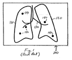
- FIG. 1 depicts a display 100 of nodules on a lung anatomical background map constructed to facilitate localization and comparative visualization of the nodules.
- key anatomical structures can be extracted from the original x-rays, CT axial sections and the like and represented in a map in several ways. For example, one can project the anatomical structures onto a 2D plane and create a projection 2D map. Another method, as shown here, is to create a line drawing type of map to represent the lung anatomy. The border of the lungs is represented by closed lines 110, 120. Other anatomical background such as the airway and vascular structures are represented by dark lines 130.
- discs 140 The approximate location of nodules relative to the background structures represented by lines 110, 120, 130 is shown by discs 140.
- the discs are brightly colored, e.g., red, to make them stand out in the display.
- the discs could blink or be emphasized in other ways.
- the size of the disc may vary in proportion to the size of the nodule.
- Fig. 1 has been successfully implemented in computer-aided nodule analysis software such as the assignee's ImageChecker® CT software and is referred to as a "nodule navigation map.”
- Illustrative apparatus for the display of such map is described in detail in assignee's US Patent 6,925,200 for "Graphical User Interface for Display of Anatomical Informations".
- assignee's US Patent 6,925,200 for "Graphical User Interface for Display of Anatomical Informations”.
- each disc is advantageously hot-linked to the CT section that contains an image of the nodule it represents so that by aligning an indicating device such as a cursor with a nodule and activating a selection device such as a mouse, the radiologist can access the corresponding CT section.
- the map provides a convenient way for the radiologist to access the individual CT section that contains an image of the nodule.
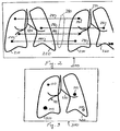
- FIG. 2 depicts a display 200 of two such images side-by-side.
- the images depict nodules on a lung anatomical background map generated by nodule analysis software running on a computer system.
- the image on the right hand side is later in time.
- the border of the lungs is represented by closed lines 210, 220.
- Other anatomical background such as the airway and vascular structures are represented by dark lines 230.
- the approximate location of nodules relative to the background structures is shown by discs 240.
- the border of the lungs is represented by closed lines 250, 260 and other anatomical background by dark lines 270.
- the approximate location of nodules relative to the background structures is represented by discs 280.
- the software determines which nodules in one image correspond to those in the other image and generates a plurality of lines 290 that extend between the images.
- some lines 291-293 begin at a disc 240 in the first image and terminate at a disc 280 at the corresponding location in the second image.
- Another line 294 extends from a disc 240 in the first image toward the corresponding location in the second image but does not terminate at any disc in the second image.
- This line is associated with a feature found in the first image but not found in the second because it has disappeared.
- Another line 295 extends from a disc 280 in the second image toward the corresponding location in the first image but does not start from any disc in the first image. This line is associated with a feature found in the second image but not found in the first image because it is new.
- lines 290 can have different colors or other distinguishing characteristics.
- lines 291-293 linking discs in both images might be blue
- line 294 relating to a disc that is not found in the second image might be green
- line 295 relating to a newly found disc in the second image might be red.
- Fig. 2 may also be condensed into a display in a single image of the lungs in which different marker symbols are used to distinguish nodules that appear in both temporal images from nodules that appear only in the first image or only in the second image.
- Fig. 3 is a display 300 of such nodules on a lung anatomical background map. Again, the border of the lungs is represented by closed lines 310, 320 and the airway and vascular structure by lines 330. Nodules that are found in both sets of temporal images are represented by solid black discs 341, 342, 343.
- Nodules that are found in the first image but not the second are represented by a disc 344 of another color such as green; and nodules that are found in the second image but not in the first are represented by a disc 345 of still another color such as red.
- a disc 344 of another color such as green
- a disc 345 of still another color such as red
- Other visually distinguishing characteristics may be used to distinguish the different kinds of nodules.
- disc 344 is represented by a small circle and disc 345 is represented by a large circle..
- the size of the disc can be in proportion to the size of the nodule.
- New nodules might be indicated by a blinking disc.
- changes in size of the nodules may also be advantageous to indicate changes in size of the nodules by color coding or other arrangements. For example, numbers might be displayed alongside the disc indicating the percent change in the size of the nodule in the second image relative to the first. Plus and minus signs could be used to show the direction of change or colors such as red and green.
- the navigational tool also includes a scroll bar on one side or the other of the display of medical images.
- Fig. 4 depicts a display 400 of two temporally related images with a scroll bar 401 along the right-hand side.
- the temporally related images are the same as those of Fig. 2 . Accordingly, they have been numbered the same and will not be described further.
- Scroll bar 401 comprises a first set of up and down scroll buttons 402, a display bar 403, a set of left and right scroll buttons 404 and a cursor 405.
- On the scroll bar are a series of horizontal lines or markers 406-410, each of which corresponds to one of the plurality of lines that extend between the pair of medical images to the left of the scroll bar.
- each marker is aligned with its corresponding line between the pair of images. Since each nodule in the images also is found in one of the CT axial sections, the markers on display bar 403 are also a visual display of the vector of CT axial slice numbers that contain a nodule.
- the visual appearance of the markers varies with the lines with which they are associated.
- they may have the same color as the line and that color may vary depending on whether the line joins features in the two images or the feature is found only in the first image in time or the second image in time.
- the marker can be a line whose length varies with the lines between the two images.
- the marker line may be longest where the associated line joins two features in the two medical images; and as in the case of markers 408, 410, the marker line may be only half that length where the line is connected to only one feature.
- the position of the shorter marker line may be varied to indicate whether the feature it connects to is in the first image by left-adjusting the marker as in the case of marker 408 or in the second image by right-adjusting the marker as in the case of marker 410.
- Fig. 5 depicts such a display where the left hand image is a map 520 that locates the nodules on the lung anatomical map and the right hand image is the CT axial section 530 that displays an image of the nodule selected by the cursor 405.
- map 520 is user selectable. It might be the map of the nodules in the more recent stack of CT axial sections, or the map of the nodules in the older stack, or a composite of the two maps such as that shown in Fig. 3 .
- the up/down scroll buttons 402 enable the user to step the display of CT sections in display 530 from one section containing a nodule to the next section containing a different nodule. Specifically, with each click of an up or down scroll button 402, display 530 goes from the display of a CT section containing one nodule to display of the CT section containing the next nodule.
- Left and right scroll buttons 404 allow the user to navigate through the entire stack of CT axial sections one at a time. Each click of a left or right button changes the display 530 to display the next axial section down or up in the stack. Thus, the user is able to view the CT sections immediately adjacent to the section in which the image of the nodule appears.
- the left and right control buttons can be used to select whether the axial section that is displayed comes from the older stack of CT sections or the newer stack.
- Additional controls may also be provided to allow the user to select the images that appear alongside the scrollbar. For example, some users may prefer to have the map displayed immediately adjacent the scrollbar instead of the axial section as in Fig. 5 . The user may also wish to compare an axial section in the more recent image stack with the corresponding axial section in an earlier image stack and may want to suppress display of the map to allow the display of the two sections side-by-side.
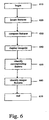
- Fig. 6 is a flowchart for the software program that generates the displays of Figs. 2-6 .
- the software program comprises a set of computer instructions stored in a computer readable medium available to the computer that generates these displays.
- the program begins a step 610 with the data representing a pair of temporally related medical images.
- the images may be actual images such as x-rays and the like or abstractions derived from such images such as projection maps or anatomical maps.
- the program locates features or regions of interest in each of the first and second medical images. For example, in the case where the medical images are of the pulmonary region, the features might be nodules.
- the program compares the two images to identify corresponding features at substantially the same location in each image.
- Corresponding features found in both medical images are identified at step 650; and features found in only one medical image are identified at step 660.
- the corresponding features may be identified by a line connecting the corresponding features in both images and the features found in only one image may be identified by a line extending from the feature in the image where it is found toward the other feature.
- the features found in both images may be marked on the displayed image in one fashion while the features found in only one image may be marked in a different fashion.
Landscapes
- Engineering & Computer Science (AREA)
- Health & Medical Sciences (AREA)
- General Health & Medical Sciences (AREA)
- Medical Informatics (AREA)
- Nuclear Medicine, Radiotherapy & Molecular Imaging (AREA)
- Radiology & Medical Imaging (AREA)
- Theoretical Computer Science (AREA)
- Primary Health Care (AREA)
- Physics & Mathematics (AREA)
- General Physics & Mathematics (AREA)
- Public Health (AREA)
- Epidemiology (AREA)
- Quality & Reliability (AREA)
- Computer Vision & Pattern Recognition (AREA)
- Computer Graphics (AREA)
- Computer Hardware Design (AREA)
- General Engineering & Computer Science (AREA)
- Software Systems (AREA)
- Apparatus For Radiation Diagnosis (AREA)
- Magnetic Resonance Imaging Apparatus (AREA)
Claims (10)
- Navigationswerkzeug zum Erleichtern des Vergleichens von ersten und zweiten zeitlich in Beziehung stehenden medizinischen Bildern, wobei das Navigationswerkzeug aufweist:ein Mittel zum automatischen Lokalisieren sich entsprechender Knoten in jedem der ersten und zweiten medizinischen Bilder,eine Anzeige (200; 400) der ersten und zweiten medizinischen Bilder Seite an Seite, wobei die zwei Bilder denselben Gegenstand zu verschiedenen Zeiten zeigen, gekennzeichnet durcheine Vielzahl von sich zwischen den Bildern erstreckenden Linien (290) mit wenigstens einer ersten Linie (291, 292, 293), die an einem Knoten (240) an einem ersten Ort in dem ersten Bild beginnt und an einem entsprechenden Knoten (280) an einem entsprechenden Ort in dem zweiten Bild endet, und wenigstens einer zweiten Linie (294, 295), die sich von einem Knoten, der an einem zweiten Ort in einem der Bilder gefunden wurde, zu einem entsprechenden zweiten Ort in dem anderen Bild, in dem kein entsprechender Knoten gefunden wurde, erstreckt, wobei die ersten und zweiten Linien ein verschiedenes Erscheinungsbild aufweisen.
- Werkzeug nach Anspruch 1, das weiterhin eine Bildlaufleiste (401) neben dem ersten und zweiten Bild aufweist, die Marker (406...410) umfasst, die mit den ersten und zweiten Linien (290) ausgerichtet sind.
- Werkzeug nach Anspruch 2, wobei der mit der ersten Linie ausgerichtete Marker ein Erscheinungsbild aufweist, das sich von dem Erscheinungsbild des mit der zweiten Linie ausgerichteten Markers unterscheidet.
- Werkzeug nach Anspruch 3, wobei die Marker (406...410) entweder Linien verschiedener Länge sind oder verschiedene Farben aufweisen.
- Werkzeug nach Anspruch 1, wobei die ersten und zweiten Linien verschiedene Farben aufweisen.
- Werkzeug nach einem der vorhergehenden Ansprüche, wobei die Bilder Bilder einer Lunge oder beider Lungen sind.
- Werkzeug nach Anspruch 1, wobei, wenn sich die zweite Linie (295) von einem Knoten (280) an einem zweiten Ort in dem zweiten Bild zu dem entsprechenden zweiten Ort in dem ersten Bild, in dem der Knoten nicht erscheint, erstreckt, das Werkzeug weiter eine dritte Linie aufweist, die sich von einem Knoten an einem dritten Ort in dem ersten Bild zu einem entsprechenden dritten Ort in dem zweiten Bild, in dem der Knoten nicht erscheint, erstreckt.
- Werkzeug nach Anspruch 7, wobei die ersten, zweiten und dritten Linien ein verschiedenes Erscheinungsbild aufweisen.
- Werkzeug nach Anspruch 8, wobei die ersten, zweiten und dritten Linien verschiedene Farben haben.
- Computergestütztes Verfahren zum Vergleichen erster und zweiter zeitlich in Beziehung stehender medizinischer Bilder, wobei das Verfahren aufweist:Lokalisieren sich entsprechender Knoten in jedem der ersten und zweiten medizinischen Bilder,Anzeigen der ersten und zweiten medizinischen Bilder Seite an Seite, wobei das Verfahren dadurch gekennzeichnet ist, dass es aufweist:Identifizieren der sich entsprechenden Knoten in den medizinischen Bildern undIdentifizieren wenigstens eines Knotens in den medizinischen Bildern, der in einem der ersten und zweiten medizinischen Bilder, nicht aber in dem anderen, gefunden wurde,Anzeigen des ersten und zweiten medizinischen Bildes mit wenigstens einer ersten Linie (291, 292, 293), die sich zwischen einem Knoten (240) an einem ersten Ort in dem ersten Bild und einem entsprechenden Knoten (280) an einem entsprechenden ersten Ort in dem zweiten Bild erstreckt, und einer zweiten Linie (294, 295), die sich von einem Knoten an einem zweiten Ort in einem der Bilder zu einem entsprechenden zweiten Ort in dem anderen Bild, in dem kein entsprechender Knoten gefunden wurde, erstreckt, wobei die ersten und zweiten Linien ein verschiedenes Erscheinungsbild aufweisen.
Applications Claiming Priority (2)
| Application Number | Priority Date | Filing Date | Title |
|---|---|---|---|
| US11/344,832 US7630531B2 (en) | 2006-01-31 | 2006-01-31 | Enhanced navigational tools for comparing medical images |
| PCT/US2007/002980 WO2007089941A2 (en) | 2006-01-31 | 2007-01-30 | Enhanced navigational tools for comparing medical images |
Publications (3)
| Publication Number | Publication Date |
|---|---|
| EP1979856A2 EP1979856A2 (de) | 2008-10-15 |
| EP1979856A4 EP1979856A4 (de) | 2011-12-07 |
| EP1979856B1 true EP1979856B1 (de) | 2014-04-02 |
Family
ID=38322135
Family Applications (1)
| Application Number | Title | Priority Date | Filing Date |
|---|---|---|---|
| EP07762774.3A Active EP1979856B1 (de) | 2006-01-31 | 2007-01-30 | Erweiterte navigationshilfsmittel für den vergleich von medizinischen bildern |
Country Status (4)
| Country | Link |
|---|---|
| US (1) | US7630531B2 (de) |
| EP (1) | EP1979856B1 (de) |
| JP (1) | JP5114630B2 (de) |
| WO (1) | WO2007089941A2 (de) |
Families Citing this family (46)
| Publication number | Priority date | Publication date | Assignee | Title |
|---|---|---|---|---|
| US7616801B2 (en) | 2002-11-27 | 2009-11-10 | Hologic, Inc. | Image handling and display in x-ray mammography and tomosynthesis |
| US8565372B2 (en) | 2003-11-26 | 2013-10-22 | Hologic, Inc | System and method for low dose tomosynthesis |
| US7577282B2 (en) | 2002-11-27 | 2009-08-18 | Hologic, Inc. | Image handling and display in X-ray mammography and tomosynthesis |
| US7123684B2 (en) | 2002-11-27 | 2006-10-17 | Hologic, Inc. | Full field mammography with tissue exposure control, tomosynthesis, and dynamic field of view processing |
| US10638994B2 (en) | 2002-11-27 | 2020-05-05 | Hologic, Inc. | X-ray mammography with tomosynthesis |
| EP3106094B1 (de) | 2004-11-26 | 2021-09-08 | Hologic, Inc. | Integriertes multimodus-mammographie-/tomosynthese-röntgensystem |
| US7518619B2 (en) * | 2005-11-07 | 2009-04-14 | General Electric Company | Method and apparatus for integrating three-dimensional and two-dimensional monitors with medical diagnostic imaging workstations |
| WO2008075272A1 (en) * | 2006-12-19 | 2008-06-26 | Koninklijke Philips Electronics N.V. | Apparatus and method for indicating likely computer-detected false positives in medical imaging data |
| US7936910B2 (en) * | 2007-09-20 | 2011-05-03 | James Hamilton Watt | Method, system and software for displaying medical images |
| US20100063842A1 (en) * | 2008-09-08 | 2010-03-11 | General Electric Company | System and methods for indicating an image location in an image stack |
| US9146663B2 (en) | 2008-12-08 | 2015-09-29 | Hologic, Inc. | Displaying computer-aided detection information with associated breast tomosynthesis image information |
| JP2012513279A (ja) * | 2008-12-23 | 2012-06-14 | コーニンクレッカ フィリップス エレクトロニクス エヌ ヴィ | 医療異常監視システム及びその操作方法 |
| JP5455470B2 (ja) * | 2009-07-02 | 2014-03-26 | 株式会社東芝 | 医用画像読影システム |
| US8326012B2 (en) * | 2009-10-07 | 2012-12-04 | Hologic, Inc. | Selective display of computer-aided detection findings with associated breast X-ray mammogram and/or tomosynthesis image information |
| US9734285B2 (en) * | 2010-05-20 | 2017-08-15 | General Electric Company | Anatomy map navigator systems and methods of use |
| US8761467B2 (en) * | 2010-10-04 | 2014-06-24 | General Electric Company | Method and apparatus for assessing motion correction |
| US9063643B2 (en) * | 2011-03-29 | 2015-06-23 | Boston Scientific Neuromodulation Corporation | System and method for leadwire location |
| US20140204242A1 (en) * | 2011-06-27 | 2014-07-24 | Koninklijke Philips N.V. | Exam review facilitated by clinical findings management with anatomical tagging |
| US10171734B2 (en) | 2012-02-27 | 2019-01-01 | Ovio Technologies, Inc. | Rotatable imaging system |
| US20130322712A1 (en) * | 2012-06-05 | 2013-12-05 | Siemens Medical Solutions Usa, Inc. | System for Comparing Medical Images |
| GB201210172D0 (en) * | 2012-06-08 | 2012-07-25 | Siemens Medical Solutions | Navigation mini-map for structured reading |
| WO2013191036A1 (ja) * | 2012-06-20 | 2013-12-27 | 株式会社 東芝 | 医用画像処理装置、磁気共鳴イメージング装置、医用画像処理方法及び磁気共鳴イメージング方法 |
| KR102047696B1 (ko) * | 2013-02-20 | 2019-11-22 | 엘지전자 주식회사 | 이동 단말기 및 이의 제어 방법 |
| CN104423868B (zh) * | 2013-09-04 | 2019-03-08 | 腾讯科技(深圳)有限公司 | 电子书阅读定位方法及装置 |
| JP6323025B2 (ja) * | 2014-01-21 | 2018-05-16 | 富士通株式会社 | 表示制御プログラム、表示制御装置及び表示制御システム |
| EP3164075B1 (de) | 2014-07-02 | 2021-03-24 | Covidien LP | Vereinheitlichtes koordinatensystem für mehrere ct-scans von patientenlungen |
| CN104323860B (zh) * | 2014-11-07 | 2018-08-31 | 常州朗合医疗器械有限公司 | 导航路径规划装置和方法 |
| JP6598565B2 (ja) * | 2015-08-06 | 2019-10-30 | キヤノン株式会社 | 画像処理装置、画像処理方法及びプログラム |
| CN106803234B (zh) * | 2015-11-26 | 2020-06-16 | 腾讯科技(深圳)有限公司 | 图片编辑中的图片显示控制方法及装置 |
| WO2017185028A1 (en) | 2016-04-22 | 2017-10-26 | Hologic, Inc. | Tomosynthesis with shifting focal spot x-ray system using an addressable array |
| EP3326535B1 (de) | 2016-11-25 | 2019-06-12 | ScreenPoint Medical | Anzeigesystem zum anzeigen digitaler brusttomosynthesedaten |
| JP2018175216A (ja) * | 2017-04-10 | 2018-11-15 | コニカミノルタ株式会社 | 医用画像表示装置及びプログラム |
| DE202018006917U1 (de) | 2017-08-16 | 2024-07-18 | Hologic Inc. | Techniken zur Patientenbewegungsartefaktkompensation bei Brustbildgebung |
| EP3449835B1 (de) | 2017-08-22 | 2023-01-11 | Hologic, Inc. | Computertomografiesystem und methode zur bildgebung mehrerer anatomischer ziele |
| JP6950507B2 (ja) * | 2017-12-12 | 2021-10-13 | コニカミノルタ株式会社 | 動態画像処理装置 |
| US11090017B2 (en) | 2018-09-13 | 2021-08-17 | Hologic, Inc. | Generating synthesized projection images for 3D breast tomosynthesis or multi-mode x-ray breast imaging |
| EP3682804A1 (de) * | 2019-01-18 | 2020-07-22 | Samsung Electronics Co., Ltd. | Röntgenbildgebungsvorrichtung und steuerungsverfahren dafür |
| EP3832689A3 (de) | 2019-12-05 | 2021-08-11 | Hologic, Inc. | Systeme und verfahren für verbesserte röntgenröhrenlebensdauer |
| US11471118B2 (en) | 2020-03-27 | 2022-10-18 | Hologic, Inc. | System and method for tracking x-ray tube focal spot position |
| TWI799705B (zh) * | 2020-05-20 | 2023-04-21 | 倍利科技股份有限公司 | 醫學影像輔助判讀系統 |
| US20220291823A1 (en) * | 2021-03-11 | 2022-09-15 | GE Precision Healthcare LLC | Enhanced Visualization And Playback Of Ultrasound Image Loops Using Identification Of Key Frames Within The Image Loops |
| US11786191B2 (en) | 2021-05-17 | 2023-10-17 | Hologic, Inc. | Contrast-enhanced tomosynthesis with a copper filter |
| US20230051081A1 (en) * | 2021-08-11 | 2023-02-16 | Mim Software Inc. | Registration chaining with information transfer |
| US12315158B2 (en) * | 2021-11-24 | 2025-05-27 | GE Precision Healthcare LLC | System and method for visualizing placement of a medical tube or line |
| US12229953B2 (en) | 2021-11-24 | 2025-02-18 | GE Precision Healthcare LLC | System and method for visualizing placement of a medical tube or line |
| US12414217B2 (en) | 2022-02-07 | 2025-09-09 | Hologic, Inc. | Systems and methods for adaptively controlling filament current in an X-ray tube |
Family Cites Families (12)
| Publication number | Priority date | Publication date | Assignee | Title |
|---|---|---|---|---|
| JP3085724B2 (ja) * | 1991-05-10 | 2000-09-11 | 株式会社東芝 | 医用診断支援システム |
| JPH06215108A (ja) * | 1992-11-27 | 1994-08-05 | Fuji Photo Film Co Ltd | 放射線画像の位置合せ方法 |
| EP0616290B1 (de) * | 1993-03-01 | 2003-02-05 | Kabushiki Kaisha Toshiba | System zur Verarbeitung von medizinischen Daten zur Unterstützung der Diagnose |
| JPH0877329A (ja) * | 1994-09-02 | 1996-03-22 | Konica Corp | 時系列処理画像の表示装置 |
| US6222541B1 (en) * | 1998-01-20 | 2001-04-24 | International Business Machines Corporation | Method and apparatus for fast-path location and selection of links |
| JP2001157675A (ja) * | 1999-12-02 | 2001-06-12 | Fuji Photo Film Co Ltd | 画像表示方法および画像表示装置 |
| US7072501B2 (en) | 2000-11-22 | 2006-07-04 | R2 Technology, Inc. | Graphical user interface for display of anatomical information |
| US7130457B2 (en) * | 2001-07-17 | 2006-10-31 | Accuimage Diagnostics Corp. | Systems and graphical user interface for analyzing body images |
| JP4341210B2 (ja) * | 2002-07-04 | 2009-10-07 | コニカミノルタホールディングス株式会社 | 医用画像処理装置、医用画像処理方法、プログラム及び記録媒体 |
| US7403646B2 (en) * | 2002-10-24 | 2008-07-22 | Canon Kabushiki Kaisha | Image processing apparatus, image processing method, program, and recording medium for generating a difference image from a first radiographic image and second radiographic image |
| JP4731127B2 (ja) * | 2004-05-26 | 2011-07-20 | 株式会社日立メディコ | 画像診断支援装置及び方法 |
| JP4786150B2 (ja) | 2004-07-07 | 2011-10-05 | 株式会社東芝 | 超音波診断装置および画像処理装置 |
-
2006
- 2006-01-31 US US11/344,832 patent/US7630531B2/en active Active
-
2007
- 2007-01-30 WO PCT/US2007/002980 patent/WO2007089941A2/en not_active Ceased
- 2007-01-30 EP EP07762774.3A patent/EP1979856B1/de active Active
- 2007-01-30 JP JP2008553387A patent/JP5114630B2/ja active Active
Also Published As
| Publication number | Publication date |
|---|---|
| US20070177780A1 (en) | 2007-08-02 |
| JP5114630B2 (ja) | 2013-01-09 |
| EP1979856A4 (de) | 2011-12-07 |
| WO2007089941A2 (en) | 2007-08-09 |
| WO2007089941A3 (en) | 2008-05-02 |
| JP2009525143A (ja) | 2009-07-09 |
| EP1979856A2 (de) | 2008-10-15 |
| US7630531B2 (en) | 2009-12-08 |
Similar Documents
| Publication | Publication Date | Title |
|---|---|---|
| EP1979856B1 (de) | Erweiterte navigationshilfsmittel für den vergleich von medizinischen bildern | |
| US12333087B2 (en) | Interactive 3D cursor | |
| US10772591B2 (en) | Displaying computer-aided detection information with associated breast tomosynthesis image information | |
| US8160320B2 (en) | Medical image display apparatus, method and program, and recording medium for the program | |
| US9763633B2 (en) | Displaying computer-aided detection information with associated breast tomosynthesis image information | |
| US7130457B2 (en) | Systems and graphical user interface for analyzing body images | |
| US6901277B2 (en) | Methods for generating a lung report | |
| JP4253497B2 (ja) | コンピュータ支援診断装置 | |
| KR20140055152A (ko) | 병변 진단 보조 장치 및 방법 | |
| US10188361B2 (en) | System for synthetic display of multi-modality data | |
| US20070110295A1 (en) | System and method for enhanced viewing of rib metastasis | |
| EP2513828B1 (de) | Associating acquired images with objects | |
| EP4310852A1 (de) | Systeme und verfahren zum modifizieren von bilddaten eines medizinischen bilddatensatzes |
Legal Events
| Date | Code | Title | Description |
|---|---|---|---|
| PUAI | Public reference made under article 153(3) epc to a published international application that has entered the european phase |
Free format text: ORIGINAL CODE: 0009012 |
|
| 17P | Request for examination filed |
Effective date: 20080717 |
|
| AK | Designated contracting states |
Kind code of ref document: A2 Designated state(s): AT BE BG CH CY CZ DE DK EE ES FI FR GB GR HU IE IS IT LI LT LU LV MC NL PL PT RO SE SI SK TR |
|
| AX | Request for extension of the european patent |
Extension state: AL BA HR MK RS |
|
| RAP1 | Party data changed (applicant data changed or rights of an application transferred) |
Owner name: MEVIS MEDICAL SOLUTIONS, INC. |
|
| REG | Reference to a national code |
Ref country code: DE Ref legal event code: R079 Ref document number: 602007035896 Country of ref document: DE Free format text: PREVIOUS MAIN CLASS: G06K0009000000 Ipc: G06T0007000000 |
|
| A4 | Supplementary search report drawn up and despatched |
Effective date: 20111109 |
|
| RIC1 | Information provided on ipc code assigned before grant |
Ipc: G06T 7/00 20060101AFI20111103BHEP |
|
| RAP1 | Party data changed (applicant data changed or rights of an application transferred) |
Owner name: MEVIS MEDICAL SOLUTIONS AG |
|
| 17Q | First examination report despatched |
Effective date: 20120710 |
|
| DAX | Request for extension of the european patent (deleted) | ||
| GRAP | Despatch of communication of intention to grant a patent |
Free format text: ORIGINAL CODE: EPIDOSNIGR1 |
|
| INTG | Intention to grant announced |
Effective date: 20131022 |
|
| GRAS | Grant fee paid |
Free format text: ORIGINAL CODE: EPIDOSNIGR3 |
|
| GRAA | (expected) grant |
Free format text: ORIGINAL CODE: 0009210 |
|
| RAP1 | Party data changed (applicant data changed or rights of an application transferred) |
Owner name: MEVIS MEDICAL SOLUTIONS AG |
|
| AK | Designated contracting states |
Kind code of ref document: B1 Designated state(s): AT BE BG CH CY CZ DE DK EE ES FI FR GB GR HU IE IS IT LI LT LU LV MC NL PL PT RO SE SI SK TR |
|
| REG | Reference to a national code |
Ref country code: GB Ref legal event code: FG4D |
|
| REG | Reference to a national code |
Ref country code: AT Ref legal event code: REF Ref document number: 660514 Country of ref document: AT Kind code of ref document: T Effective date: 20140415 Ref country code: CH Ref legal event code: EP |
|
| REG | Reference to a national code |
Ref country code: IE Ref legal event code: FG4D |
|
| REG | Reference to a national code |
Ref country code: DE Ref legal event code: R096 Ref document number: 602007035896 Country of ref document: DE Effective date: 20140515 |
|
| REG | Reference to a national code |
Ref country code: AT Ref legal event code: MK05 Ref document number: 660514 Country of ref document: AT Kind code of ref document: T Effective date: 20140402 |
|
| REG | Reference to a national code |
Ref country code: NL Ref legal event code: VDEP Effective date: 20140402 |
|
| REG | Reference to a national code |
Ref country code: LT Ref legal event code: MG4D |
|
| PG25 | Lapsed in a contracting state [announced via postgrant information from national office to epo] |
Ref country code: CZ Free format text: LAPSE BECAUSE OF FAILURE TO SUBMIT A TRANSLATION OF THE DESCRIPTION OR TO PAY THE FEE WITHIN THE PRESCRIBED TIME-LIMIT Effective date: 20140402 Ref country code: NL Free format text: LAPSE BECAUSE OF FAILURE TO SUBMIT A TRANSLATION OF THE DESCRIPTION OR TO PAY THE FEE WITHIN THE PRESCRIBED TIME-LIMIT Effective date: 20140402 Ref country code: LT Free format text: LAPSE BECAUSE OF FAILURE TO SUBMIT A TRANSLATION OF THE DESCRIPTION OR TO PAY THE FEE WITHIN THE PRESCRIBED TIME-LIMIT Effective date: 20140402 Ref country code: FI Free format text: LAPSE BECAUSE OF FAILURE TO SUBMIT A TRANSLATION OF THE DESCRIPTION OR TO PAY THE FEE WITHIN THE PRESCRIBED TIME-LIMIT Effective date: 20140402 Ref country code: GR Free format text: LAPSE BECAUSE OF FAILURE TO SUBMIT A TRANSLATION OF THE DESCRIPTION OR TO PAY THE FEE WITHIN THE PRESCRIBED TIME-LIMIT Effective date: 20140703 Ref country code: IS Free format text: LAPSE BECAUSE OF FAILURE TO SUBMIT A TRANSLATION OF THE DESCRIPTION OR TO PAY THE FEE WITHIN THE PRESCRIBED TIME-LIMIT Effective date: 20140802 Ref country code: CY Free format text: LAPSE BECAUSE OF FAILURE TO SUBMIT A TRANSLATION OF THE DESCRIPTION OR TO PAY THE FEE WITHIN THE PRESCRIBED TIME-LIMIT Effective date: 20140402 Ref country code: BG Free format text: LAPSE BECAUSE OF FAILURE TO SUBMIT A TRANSLATION OF THE DESCRIPTION OR TO PAY THE FEE WITHIN THE PRESCRIBED TIME-LIMIT Effective date: 20140702 |
|
| PG25 | Lapsed in a contracting state [announced via postgrant information from national office to epo] |
Ref country code: LV Free format text: LAPSE BECAUSE OF FAILURE TO SUBMIT A TRANSLATION OF THE DESCRIPTION OR TO PAY THE FEE WITHIN THE PRESCRIBED TIME-LIMIT Effective date: 20140402 Ref country code: ES Free format text: LAPSE BECAUSE OF FAILURE TO SUBMIT A TRANSLATION OF THE DESCRIPTION OR TO PAY THE FEE WITHIN THE PRESCRIBED TIME-LIMIT Effective date: 20140402 Ref country code: SE Free format text: LAPSE BECAUSE OF FAILURE TO SUBMIT A TRANSLATION OF THE DESCRIPTION OR TO PAY THE FEE WITHIN THE PRESCRIBED TIME-LIMIT Effective date: 20140402 Ref country code: PL Free format text: LAPSE BECAUSE OF FAILURE TO SUBMIT A TRANSLATION OF THE DESCRIPTION OR TO PAY THE FEE WITHIN THE PRESCRIBED TIME-LIMIT Effective date: 20140402 Ref country code: AT Free format text: LAPSE BECAUSE OF FAILURE TO SUBMIT A TRANSLATION OF THE DESCRIPTION OR TO PAY THE FEE WITHIN THE PRESCRIBED TIME-LIMIT Effective date: 20140402 |
|
| PG25 | Lapsed in a contracting state [announced via postgrant information from national office to epo] |
Ref country code: PT Free format text: LAPSE BECAUSE OF FAILURE TO SUBMIT A TRANSLATION OF THE DESCRIPTION OR TO PAY THE FEE WITHIN THE PRESCRIBED TIME-LIMIT Effective date: 20140804 |
|
| REG | Reference to a national code |
Ref country code: DE Ref legal event code: R097 Ref document number: 602007035896 Country of ref document: DE |
|
| PG25 | Lapsed in a contracting state [announced via postgrant information from national office to epo] |
Ref country code: BE Free format text: LAPSE BECAUSE OF FAILURE TO SUBMIT A TRANSLATION OF THE DESCRIPTION OR TO PAY THE FEE WITHIN THE PRESCRIBED TIME-LIMIT Effective date: 20140402 Ref country code: DK Free format text: LAPSE BECAUSE OF FAILURE TO SUBMIT A TRANSLATION OF THE DESCRIPTION OR TO PAY THE FEE WITHIN THE PRESCRIBED TIME-LIMIT Effective date: 20140402 Ref country code: SK Free format text: LAPSE BECAUSE OF FAILURE TO SUBMIT A TRANSLATION OF THE DESCRIPTION OR TO PAY THE FEE WITHIN THE PRESCRIBED TIME-LIMIT Effective date: 20140402 Ref country code: EE Free format text: LAPSE BECAUSE OF FAILURE TO SUBMIT A TRANSLATION OF THE DESCRIPTION OR TO PAY THE FEE WITHIN THE PRESCRIBED TIME-LIMIT Effective date: 20140402 Ref country code: RO Free format text: LAPSE BECAUSE OF FAILURE TO SUBMIT A TRANSLATION OF THE DESCRIPTION OR TO PAY THE FEE WITHIN THE PRESCRIBED TIME-LIMIT Effective date: 20140402 |
|
| PLBE | No opposition filed within time limit |
Free format text: ORIGINAL CODE: 0009261 |
|
| STAA | Information on the status of an ep patent application or granted ep patent |
Free format text: STATUS: NO OPPOSITION FILED WITHIN TIME LIMIT |
|
| 26N | No opposition filed |
Effective date: 20150106 |
|
| PG25 | Lapsed in a contracting state [announced via postgrant information from national office to epo] |
Ref country code: IT Free format text: LAPSE BECAUSE OF FAILURE TO SUBMIT A TRANSLATION OF THE DESCRIPTION OR TO PAY THE FEE WITHIN THE PRESCRIBED TIME-LIMIT Effective date: 20140402 |
|
| REG | Reference to a national code |
Ref country code: DE Ref legal event code: R097 Ref document number: 602007035896 Country of ref document: DE Effective date: 20150106 |
|
| PG25 | Lapsed in a contracting state [announced via postgrant information from national office to epo] |
Ref country code: SI Free format text: LAPSE BECAUSE OF FAILURE TO SUBMIT A TRANSLATION OF THE DESCRIPTION OR TO PAY THE FEE WITHIN THE PRESCRIBED TIME-LIMIT Effective date: 20140402 |
|
| REG | Reference to a national code |
Ref country code: CH Ref legal event code: PL |
|
| PG25 | Lapsed in a contracting state [announced via postgrant information from national office to epo] |
Ref country code: LU Free format text: LAPSE BECAUSE OF FAILURE TO SUBMIT A TRANSLATION OF THE DESCRIPTION OR TO PAY THE FEE WITHIN THE PRESCRIBED TIME-LIMIT Effective date: 20150130 |
|
| PG25 | Lapsed in a contracting state [announced via postgrant information from national office to epo] |
Ref country code: MC Free format text: LAPSE BECAUSE OF FAILURE TO SUBMIT A TRANSLATION OF THE DESCRIPTION OR TO PAY THE FEE WITHIN THE PRESCRIBED TIME-LIMIT Effective date: 20140402 |
|
| PG25 | Lapsed in a contracting state [announced via postgrant information from national office to epo] |
Ref country code: CH Free format text: LAPSE BECAUSE OF NON-PAYMENT OF DUE FEES Effective date: 20150131 Ref country code: LI Free format text: LAPSE BECAUSE OF NON-PAYMENT OF DUE FEES Effective date: 20150131 |
|
| REG | Reference to a national code |
Ref country code: IE Ref legal event code: MM4A |
|
| REG | Reference to a national code |
Ref country code: FR Ref legal event code: PLFP Year of fee payment: 10 |
|
| PG25 | Lapsed in a contracting state [announced via postgrant information from national office to epo] |
Ref country code: IE Free format text: LAPSE BECAUSE OF NON-PAYMENT OF DUE FEES Effective date: 20150130 |
|
| REG | Reference to a national code |
Ref country code: FR Ref legal event code: PLFP Year of fee payment: 11 |
|
| PG25 | Lapsed in a contracting state [announced via postgrant information from national office to epo] |
Ref country code: HU Free format text: LAPSE BECAUSE OF FAILURE TO SUBMIT A TRANSLATION OF THE DESCRIPTION OR TO PAY THE FEE WITHIN THE PRESCRIBED TIME-LIMIT; INVALID AB INITIO Effective date: 20070130 |
|
| PG25 | Lapsed in a contracting state [announced via postgrant information from national office to epo] |
Ref country code: TR Free format text: LAPSE BECAUSE OF FAILURE TO SUBMIT A TRANSLATION OF THE DESCRIPTION OR TO PAY THE FEE WITHIN THE PRESCRIBED TIME-LIMIT Effective date: 20140402 |
|
| REG | Reference to a national code |
Ref country code: FR Ref legal event code: PLFP Year of fee payment: 12 |
|
| P01 | Opt-out of the competence of the unified patent court (upc) registered |
Effective date: 20230528 |
|
| PGFP | Annual fee paid to national office [announced via postgrant information from national office to epo] |
Ref country code: GB Payment date: 20241224 Year of fee payment: 19 |
|
| PGFP | Annual fee paid to national office [announced via postgrant information from national office to epo] |
Ref country code: FR Payment date: 20241219 Year of fee payment: 19 |
|
| PGFP | Annual fee paid to national office [announced via postgrant information from national office to epo] |
Ref country code: DE Payment date: 20241218 Year of fee payment: 19 |